JP2017121142A - Snatch block for cable installation work - Google Patents
Snatch block for cable installation work Download PDFInfo
- Publication number
- JP2017121142A JP2017121142A JP2015257164A JP2015257164A JP2017121142A JP 2017121142 A JP2017121142 A JP 2017121142A JP 2015257164 A JP2015257164 A JP 2015257164A JP 2015257164 A JP2015257164 A JP 2015257164A JP 2017121142 A JP2017121142 A JP 2017121142A
- Authority
- JP
- Japan
- Prior art keywords
- cable
- operation rope
- fixing mechanism
- side plate
- rope
- Prior art date
- Legal status (The legal status is an assumption and is not a legal conclusion. Google has not performed a legal analysis and makes no representation as to the accuracy of the status listed.)
- Granted
Links
Images


Landscapes
- Electric Cable Installation (AREA)
Abstract
Description
この発明は、柱上開閉器が設けられた電柱においてケーブルの架設作業を行う際に用いる金車に関する。 The present invention relates to a gold wheel used when a cable is installed in a utility pole provided with a pole switch.
特許文献1には、柱上に設置された区分開閉器の開閉操作用ハンドルの左右両端側に、所定長さの操作用索条の両端を夫々繋いで垂れ下がり状に吊着すると共に、該操作用索条の折り返し部分となる巻掛け部を挟む両側であって、少なくとも開閉操作用ハンドルの開または閉操作ストローク長を超える距離を隔てた位置に夫々牽引用係合部を設けた上、当該操作用索条巻掛け部を、巻掛け装置部の巻掛け車に捲回して同操作用索条全体が緊張状となる如く組み合わせる一方、巻掛け装置部には、外部からロックおよびアンロック可能とする回転仮止め機構が組み込まれてなる電柱上開閉器の開閉操作装置について記載されている。 In Patent Literature 1, both ends of an operation cable having a predetermined length are respectively connected to both left and right ends of an opening / closing operation handle of a section switch installed on a pillar, and suspended in a hanging shape. On both sides of the wrapping portion that is the turn-up portion of the rope, the traction engagement portions are provided at positions that are separated from each other by at least a distance exceeding the opening or closing operation stroke length of the opening / closing operation handle. The operating wire wrapping part is wound around the winding wheel of the winding device part and combined so that the entire operating rope becomes tensioned, while the winding device part can be locked and unlocked from the outside Is described as an opening / closing operation device for an electric pole top switch, in which a rotation temporary fixing mechanism is incorporated.
特許文献2には、柱上開閉器の開閉操作綱の固定装置について記載されている。開閉操作綱用固定装置は、綱固定具とガイド部材を備え、綱固定具の基部材は取着板と受板を備え、取着板には二箇所に挿通口が並設され、受板には凹溝が二箇所に並設され、受板は、凹溝を除く部分の正面側は面一となり、受板の中央部の、ボルト孔には裏側からボルトが挿通され、押え部材の、凹溝の上下端部には案内部が設けられ、押え部材は、ボルト孔をボルトにはめ込み、ボルトにワッシャをはめ込み、更にナットを螺合して装着されている。
特許文献1に記載されているように、柱上開閉器は、人が開閉操作を行うための操作綱(操作用索条)を備えている。操作綱の上端部は、柱上開閉器の開閉制御を行うための操作ハンドルに接続されており、電力線や通信線等のケーブルの架設作業に際し、電気技術者等の作業者は、この操作綱を使って操作ハンドルを操作することにより停電操作や受電操作を行う。 As described in Patent Document 1, the pole switch includes an operation rope (operation rope) for a person to perform an opening / closing operation. The upper end of the operation rope is connected to an operation handle for controlling the opening and closing of the pole switch, and an operator such as an electrician can use this operation rope when laying cables such as power lines and communication lines. Power outage operation and power reception operation are performed by operating the operation handle using.
図7に柱上開閉器5が設けられた電柱2において作業者7が金車30を用いてケーブル3の架設作業を行っている様子を示す。ケーブル3の架設作業に際し、まず作業者7は、ケーブル3の端部にガイドロープ(引き綱)を連結する。続いて作業者7は、ガイドロープを電柱2の所定の高さ位置に設けた金車30に引き通し、その後、ガイドロープを引いてケーブル3を隣接する電柱2間に渡していく。
FIG. 7 shows a state where the operator 7 is performing the construction work of the
ここで操作綱6a,6bの誤操作は感電事故や停電事故に繋がるため、上記の作業に際し、作業者7は身体や道具(各種工具、ガイドロープ、ケーブル3等)が操作綱6a,6bに触れる等しないよう常に気を遣いつつ作業を進める必要がある。とくに操作綱6a,6bよりも電柱2側にケーブル3を敷設する場合もあり、その場合はとくに慎重に作業を進める必要がある。
Here, since an erroneous operation of the operation ropes 6a and 6b leads to an electric shock accident and a power failure, the worker 7 touches the
尚、電柱2には操作綱6a,6bを固定するためのロック機構8が設けられているが、ロック機構8は電柱2の比較的低い位置に設けられており、柱上開閉器5とロック機構8との間には距離があるため、この間で作業する作業者7の身体や道具が操作綱6a,6bに触れると操作綱6a,6bが上下に動いてしまう可能性がある。
The
本発明はこうした背景に鑑みてなされたもので、柱上開閉器が設けられている電柱において金車を用いてケーブルの架設作業を行う際の操作綱の誤操作を防ぐことを目的としている。 This invention is made | formed in view of such a background, and it aims at preventing the erroneous operation of the operating rope at the time of constructing a cable using a gold wheel in the utility pole provided with the pole switch.
上記目的を達成するための本発明の一つは、柱上開閉器が設けられた電柱においてケーブルの架設作業を行う際に用いる金車であって、前記ケーブルを支持する支持機構を有する筐体と、前記筐体を前記電柱の所定の高さ位置に固定する固定機構と、前記筐体に設けられ、前記柱上開閉器から垂れ下がる操作綱を脱着可能に固定する操作綱固定機構と、を備える。 One aspect of the present invention for achieving the above object is a metal wheel used when a cable is installed in a utility pole provided with a pole switch, and a housing having a support mechanism for supporting the cable. A fixing mechanism that fixes the casing to a predetermined height position of the utility pole, and an operation rope fixing mechanism that is provided in the casing and that removably fixes an operating rope that hangs down from the pole switch. Prepare.
本発明によれば、柱上開閉器から垂れ下がる操作綱を、ケーブルの架設作業に用いる金車に設けられている操作綱固定機構に固定することで、作業者の身体や道具が誤って操作綱に触れた場合でも操作綱が上下に動いてしまうのを防ぐことができ、操作綱の誤操作を確実に防ぐことができる。 According to the present invention, by fixing the operation rope hanging from the pole switch to the operation rope fixing mechanism provided in the money wheel used for the cable erection work, the operator's body or tool is mistaken for the operation rope. Even when touched, the operation rope can be prevented from moving up and down, and erroneous operation of the operation rope can be reliably prevented.
本発明の他の一つは、上記ケーブル架設作業用金車であって、操作綱固定機構は、対峙する2つの平坦面の間に前記操作綱を挟持することにより前記操作綱を固定する構造を有する。 Another aspect of the present invention is the above-described cable laying work wheel, wherein the operation rope fixing mechanism fixes the operation rope by sandwiching the operation rope between two flat surfaces facing each other. Have
このように操作綱固定機構は、対峙する2つの平坦面の間に操作綱を挟持することにより操作綱を固定する構造であるので、2つの平坦面と操作綱との間の摩擦面積が大きくなり、操作綱固定機構に操作綱を固定する際に操作綱が上下に動いてしまうのを確実に防ぐことができる。 As described above, since the operation rope fixing mechanism has a structure in which the operation rope is fixed by sandwiching the operation rope between the two flat surfaces facing each other, the friction area between the two flat surfaces and the operation rope is large. Thus, when the operation rope is fixed to the operation rope fixing mechanism, it is possible to reliably prevent the operation rope from moving up and down.
本発明の他の一つは、上記ケーブル架設作業用金車であって、前記筐体は、前記対峙する2つの平坦面のうちの一つとして機能する平坦部と、前記2つの平坦面のうちの他の一つとして機能する可動板とを有し、前記可動板は蝶番機構を介して前記平坦部に設けられ、前記平坦部と前記可動板とを、当該平坦部と当該可動板との間に前記操作綱を挟持した状態で保持する係止機構を有する。 Another aspect of the present invention is the above-described cable laying work gold wheel, wherein the housing includes a flat portion that functions as one of the two flat surfaces facing each other, and the two flat surfaces. A movable plate that functions as the other one of them, and the movable plate is provided on the flat portion via a hinge mechanism, and the flat portion and the movable plate are connected to the flat portion and the movable plate. And a holding mechanism for holding the operation rope in a sandwiched state.
このように筐体の平坦部に蝶番機構を介して可動板を設けるとともに操作綱を挟持した状態で保持するための係止機構を設けることで、操作綱固定機構を容易かつ低コストで実現することができる。 In this way, by providing the movable plate via the hinge mechanism on the flat portion of the housing and by providing the locking mechanism for holding the operation rope in a sandwiched state, the operation rope fixing mechanism can be realized easily and at low cost. be able to.
本発明の他の一つは、上記ケーブル架設作業用金車であって、前記筐体は、第1の側面板、当該第1の側面板に対向する第2の側面板、上面板、及び上面板に対向する下面板を有するとともに、前記ケーブルが挿通される方向の2つの面が開口する略直方体状を呈し、前記第1の側面板に前記固定機構が設けられ、前記第2の側面板の外面は前記平坦部を構成する。 Another aspect of the present invention is the above-described cable erection work wheel, wherein the housing includes a first side plate, a second side plate facing the first side plate, an upper plate, and The second side plate has a lower surface plate facing the upper surface plate, has a substantially rectangular parallelepiped shape in which two surfaces in the direction in which the cable is inserted are opened, the fixing mechanism is provided on the first side surface plate, The outer surface of the face plate constitutes the flat portion.
このように筐体が略直方体状を呈する場合、固定機構が設けられる側の側面板(第1の側面板)に対向する側の側面板(第2の側面板)の外面を平坦部として利用することができ、操作綱固定機構を容易かつ低コストで実現することができる。 When the casing has a substantially rectangular parallelepiped shape in this way, the outer surface of the side plate (second side plate) on the side facing the side plate (first side plate) on the side where the fixing mechanism is provided is used as the flat portion. Thus, the operation rope fixing mechanism can be realized easily and at low cost.
本発明の他の一つは、上記ケーブル架設作業用金車であって、前記操作綱固定機構により前記操作綱が固定される部分の前記電柱からの水平距離を調節する水平距離調節機構を備える。 Another aspect of the present invention is the above-described cable erection work wheel, which includes a horizontal distance adjustment mechanism that adjusts a horizontal distance from the utility pole of a portion to which the operation rope is fixed by the operation rope fixing mechanism. .
電柱と柱上開閉器から垂れ下がる操作綱との間の水平方向の距離は架設作業が行われる現場ごとに必ずしも一定ではなく、操作綱が固定される部分の電柱からの水平距離と、電柱と操作綱との間の水平方向の距離とが異なると、操作綱を操作綱固定機構に脱着する際、作業者が操作綱を操作綱固定機構に引き寄せる必要があり、その際に操作綱が上下に動いてしまう可能性がある。しかし本発明では操作綱固定機構により操作綱が固定される部分の電柱からの水平距離を調節する水平距離調節機構を金車に設けているため、作業者は操作綱固定機構の操作綱が固定される部分の電柱からの水平距離が電柱と操作綱との間の水平方向の距離に一致するように調節することでき、操作綱を操作綱固定機構に脱着する際に操作綱が上下に動いてしまうのを防ぐことができる。 The horizontal distance between the utility pole and the operation rope hanging from the pole switch is not always constant for each site where the installation work is performed, the horizontal distance from the utility pole to the part where the operation rope is fixed, the utility pole and the operation When the horizontal distance between the rope and the rope is different, the operator needs to pull the rope to the rope when the rope is removed from the rope. There is a possibility of moving. However, in the present invention, since the gold wheel is provided with a horizontal distance adjusting mechanism that adjusts the horizontal distance from the utility pole of the portion where the operating rope is fixed by the operating rope fixing mechanism, the operator can fix the operating rope of the operating rope fixing mechanism. The horizontal distance from the utility pole can be adjusted to match the horizontal distance between the utility pole and the control rope, and the control rope moves up and down when the operation rope is attached to and detached from the control rope fixing mechanism. Can be prevented.
本発明の他の一つは、上記ケーブル架設作業用金車であって、前記筐体は、第1の側面板、当該第1の側面板に対向する第2の側面板、上面板、及び上面板に対向する下面板を有するとともに、前記ケーブルが挿通される方向の2つの面が開口する略直方体状を呈し、前記第2の側面板に平行に設けられて前記平坦部として機能する台座部と、前記筐体に前記台座部を水平方向にスライド可能に固定支持する水平距離調節機構とを備える。 Another aspect of the present invention is the above-described cable erection work wheel, wherein the housing includes a first side plate, a second side plate facing the first side plate, an upper plate, and A pedestal that has a lower surface plate facing the upper surface plate, has a substantially rectangular parallelepiped shape with two surfaces in the direction in which the cable is inserted, and is provided in parallel with the second side surface plate and functions as the flat portion. And a horizontal distance adjusting mechanism for fixing and supporting the pedestal portion in a slidable manner in the horizontal direction.
筐体が略直方体状を呈する場合、このように平坦部として機能する台座部を水平方向にスライド可能に固定支持することで、水平距離調節機構を容易かつ低コストで実現することができる。 When the casing has a substantially rectangular parallelepiped shape, the horizontal distance adjusting mechanism can be realized easily and at low cost by fixing and supporting the pedestal portion functioning as a flat portion in such a manner as to be slidable in the horizontal direction.
本発明の他の一つは、上記ケーブル架設作業用金車であって、前記柱上開閉器の操作ハンドルから垂れ下がる2つの操作綱のうちの一方を脱着可能に固定する第1の前記操作綱固定機構と、前記2つの操作綱のうちの他方を脱着可能に固定する第2の前記操作綱固定機構とを有する。 Another one of the present invention is the above-described cable erection work wheel, wherein the first operation rope for detachably fixing one of the two operation ropes hanging from the operation handle of the pole switch. A fixing mechanism; and a second operation rope fixing mechanism for detachably fixing the other of the two operation ropes.
柱上開閉器の操作ハンドルはシーソー構造になっており、原理的には操作ハンドルから垂れ下がる2つの操作綱の一方を操作綱固定機構を固定することで操作綱が上下に動いてしまうのを防ぐことができるが、本発明のように、第1の操作綱固定機構及び第2の操作綱固定機構によって2つの操作綱の双方を固定することで、仮に一方の操作綱の固定が解除されてしまった場合でも操作綱の誤操作を防ぐことができる。 The operation handle of the pole switch has a seesaw structure. In principle, the operation rope can be prevented from moving up and down by fixing the operation rope fixing mechanism to one of the two ropes hanging from the operation handle. However, as in the present invention, by fixing both of the two operation ropes by the first operation rope fixing mechanism and the second operation rope fixing mechanism, the fixation of one of the operation ropes is temporarily released. Even if it is stuck, it is possible to prevent erroneous operation of the operation rope.
その他、本願が開示する課題、及びその解決方法は、発明を実施するための形態の欄、及び図面により明らかにされる。 In addition, the subject which this application discloses, and its solution method are clarified by the column of the form for inventing, and drawing.
本発明によれば、柱上開閉器が設けられている電柱において金車を用いてケーブルの架設作業を行う際の操作綱の誤操作を防ぐことができる。 ADVANTAGE OF THE INVENTION According to this invention, the erroneous operation of the operation cord at the time of carrying out the cable construction work using a gold wheel in the electric pole provided with the pole switch can be prevented.
以下、本発明の実施形態につき適宜図面を参照しつつ説明する。 Hereinafter, embodiments of the present invention will be described with reference to the drawings as appropriate.
[第1実施形態]
図1及び図2に、第1実施形態として説明する金車10の構成を示している。図1は電柱2の所定の高さ位置に設けられた金車10周辺の様子を示す図であり、図2は金車10の構成を示す斜視図である。金車10は、上部に柱上開閉器(同図において不図示)が設けられた電柱2において行われる電力線や通信線等のケーブル3の架設作業(張り替え、新設等)に用いられる。ケーブル3の架設作業に際し、金車10は、電柱2に上って作業する電気技術者等の作業者によって電柱2の所定の高さ位置に設けられる。
[First Embodiment]
FIG. 1 and FIG. 2 show the configuration of a
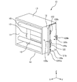
図1及び図2に示す金車10は「4面金車」と通称されるタイプのものであり、略直方体状の外観を呈する。金車10の6つの面のうち、ケーブル3やガイドロープ(引き綱)が挿通される方向(同図においてX軸の方向)の2つの面は開口している。また金車10の他の4つの面は、全体として角筒を形成する平坦な4つの板材(対向する一対の側面板11,12、対向する上面板13及び下面板14)で構成されている。4つの板材は、例えば、樹脂等の絶縁体を素材とする。
The
金車10の内部空間には、当該内部空間に挿通されるケーブル3を支持する複数のガイドローラ15(支持機構)が設けられている。ガイドローラ15は、例えば、樹脂等の絶縁体を素材とする。複数のガイドローラ15は、例えば、上記開口の方向(同図におけるX軸の方向)から眺めた場合に格子状となるように配置される。複数のガイドローラ15は、夫々、4つの板材の対峙する2つの板材に埋設されたベアリング機構(不図示)によって回動軸周りに回動可能に軸支されている。
In the internal space of the
金車10の電柱2側に位置する側の側面板11には、金車10を電柱2に固定する固定機構(不図示)が設けられている。固定機構は、電柱2の周囲に巻回される帯状のベルト4が連結されるベルト連結部(不図示)を有する。
A fixing mechanism (not shown) for fixing the
同図に示すように、金車10の側面板12には、電柱2の上部付近に設けられている柱上開閉器の操作ハンドル(不図示)から垂れ下がる2つの操作綱6a,6bを脱着可能に固定する操作綱固定機構120が設けられている。操作綱固定機構120は、平坦な外面を有する側面板12、2つの可動板121a,121b、及びこれら2つの可動板121a,121bを側面板12の外面に回動可能に支持する一つ以上の蝶番機構122を含む。可動板121a及び側面板12は、第1の操作綱固定機構120aを構成し、可動板121b及び側面板12は、第2の操作綱固定機構120bを構成する。
As shown in the drawing, two
可動板121a,121bは、いずれについてもその平面は略長方形状であり、当該平面の面積はいずれも金車10の側面板12の平面の面積の約1/2程度である。蝶番機構122は、いずれも側面板12の上辺の中点と側面の下辺の中点とを結ぶ操作綱6a,6bに平行な線(同図におけるZ軸に平行な線)がその回動軸に一致するように配設されている。
The plane of each of the
側面板12の、Z軸に平行な対向する2つの辺の夫々の中点近傍には、可動板121aを係止するための爪部125aと、可動板121bを係止するための爪部125bとが設けられている。爪部125a,125bは、いずれも鉤(かぎ)状の断面形状を有する。
A
金車10を用いたケーブル3の架設作業において操作綱6a,6bを金車10に固定する際、作業者は、可動板121a,121bを夫々、上記回動軸の周りに回動させることにより、操作綱6aについては可動板121aと側面板12との間に、操作綱6bについては可動板121bと側面板12との間に、夫々挟み込むようにする。
When the
具体的には、まず作業者は、図3(a)に示すように、側面板12と可動板121aとの間に操作綱6aを、側面板12と可動板121bとの間に操作綱6bを位置させる。続いて図3(b)に示すように、作業者は、可動板121a及び可動板121bを夫々側面板12に押し付け、可動板121aについては爪部125aに、可動板121bについては爪部125bに、夫々係止させる。これにより操作綱6aについては側面板12と可動板121aとの間に挟持されて操作綱固定機構120(第1の操作綱固定機構)に固定(ロック)され、操作綱6bについては側面板12と可動板121bとの間に挟持されて操作綱固定機構120(第2の操作綱固定機構)に固定される。
Specifically, first, as shown in FIG. 3A, the operator places the
このように、金車10を用いたケーブル3の架設作業において、作業者は、柱上開閉器5から垂れ下がる2つの操作綱6a,6bを、金車10に設けた操作綱固定機構120にシンプルな操作で容易に固定することができる。また操作綱6a,6bはいずれも作業者が存在する高さ位置の近傍で固定されるので、作業者等が誤って操作綱6a,6bに接触した場合でも操作綱6a,6bが上下に動いてしまうことがなく、操作綱6a,6bの誤操作を防ぐことができる。
In this way, in the construction work of the
尚、柱上開閉器5の操作ハンドルは一般にシーソー構造になっており、原理的には2つの操作綱6a,6bのいずれか一方のみを固定することで操作綱6a,6bが上下に動いてしまうのを防ぐことができる。しかし上記のように第1の操作綱固定機構120a及び第2の操作綱固定機構120bによって2つの操作綱6a,6bの双方を固定することで、仮に一方の操作綱の固定が解除されてしまった場合でも、操作綱6a,6bが上下に動いてしまうのを防ぐことができる。
Note that the operation handle of the pole switch 5 generally has a seesaw structure, and in principle, only one of the two
また側面板12と可動板121a,121bの操作綱6a,6bが当接する側の面が平坦(フラット)になっており、側面板12と可動板121a,121bとの間に操作綱6a,6bを挟持した際、側面板12及び可動板121a,121bと操作綱6a,6bとの間の摩擦面積が大きくなり、操作綱6a,6bを確実に固定することができる。
Further, the surface of the
またこのように側面板12と可動板121a,121bの操作綱6a,6bが当接する側の面が平坦になっていることで、操作綱6aを操作綱固定機構120に固定する際に操作綱6a,6bが上下に動くことがなく安全である。尚、操作綱6a,6bを挟み込んだ際の挟持力を増そうとして、例えば、側面板12や可動板121a,121bの操作綱6a,6bが当接する側の面を波状や段差形状とすることも考えられるが、その場合は操作綱6a,6bを操作綱固定機構120に脱着する際、操作綱6a,6bが食い込まれて引っ張られたり食い込んだ部分が緩む等して操作綱6a,6bが上下に動いてしまう可能性がある。
In addition, since the side of the
図示していないが、金車10の全部又は一部は分解可能な構造になっており、ケーブル3の架設作業の完了後等において金車10はその場で簡単にケーブル3から取り外すことができるようになっている。具体的には、ガイドローラ15の全部又は一部はその回動軸を板材(側面板11、側面板12、上面板13、下面板14)から取り外し可能な構造(回動軸を板材に沿ってスライド可能な構造、ガイドローラ15の側面側からの操作により回動軸をガイドローラ15の内部に収容可能な構造等)になっており、また板材の全部又は一部を開放可能な構造(蝶番機構等により開放可能な構造等)になっている。作業者は、板材の全部又は一部を開放するとともにガイドローラ15を取り外すことで、ケーブル3を金車10(角筒)の外部に簡単に逃がす(金車10をケーブル3から取り外す)ことができる。
Although not shown, all or a part of the
[第2実施形態]
電柱2と柱上開閉器から垂れ下がる操作綱6a,6bとの間の水平方向の距離は架設作業が行われる現場ごとに必ずしも一定ではなく、操作綱固定機構120の操作綱6a,6bが固定される部分の電柱2からの水平距離と、電柱2と操作綱6a,6bとの間の水平方向の距離とが異なると、操作綱6a,6bを操作綱固定機構120に脱着する際、作業者が操作綱6a,6bを操作綱固定機構120に引き寄せる必要があり、その際に操作綱6a,6bが上下に動いてしまう可能性がある。そこで第2実施形態では、金車10に操作綱固定機構120を水平方向に移動可能に支持する構成(水平距離調節機構)を設けて、作業者が操作綱固定機構120により操作綱6a,6bが固定される部分の電柱2からの水平距離を調節できるようにしている。
[Second Embodiment]
The horizontal distance between the
図4及び図5に、第2実施形態として説明する金車10の構成を示している。図4は電柱2の所定の高さ位置に設けられた金車10周辺の様子を示す図であり、図5は金車10の構成を示す斜視図である。これらの図に示すように、第2実施形態の金車10は、操作綱固定機構120として、その平面が金車10の側面板12と同じ程度の面積を有する略長方形状の平板からなる台座部128と、この台座部128の表面に蝶番機構122,122を介して回動可能に支持された可動板121a,121bと、台座部128を支持するL字状部材129a,129bとを備える。台座部128は、その平面が金車10の側面板12から所定距離離間した位置に側面板12と平行になるように、L字状部材129a,129bによって支持される。
4 and 5 show the configuration of the
L字状部材129a,129bは、夫々、直交する2つの矩形片(L字状部材129aについては矩形片1291a,1292a、L字状部材129bについては矩形片1291b,1292b)を有する。いずれのL字状部材129a,129bについても、一方の矩形片1291a,1291bについては台座部128の裏面(法線が−Y方向の面)に接合され、他方の矩形片1292a,1292bについては金車10の上面板13の表面(法線が+Z方向の面)に連結されている。
Each of the L-shaped
同図に示すように、他方の矩形片1292a,1292bの面内には、Y軸の方向に細長に穿孔され矩形孔が形成されており、L字状部材129a,129bは、これらの矩形孔に挿通したボルト135a,135bを金車10の上面板13に形成されたネジ穴(不図示)に螺合することにより金車10に取り付けられている。そしてボルト135a,135bを緩めることで、作業者は台座部128をY軸の方向に水平方向(同図に示すY軸の方向)に容易に移動(スライド)させることができる。
As shown in the figure, in the plane of the other
作業者は、操作綱6a,6bを操作綱固定機構120に固定する際、操作綱6a,6bが上下に動いてしまうことのないように、電柱2と操作綱6a,6bとの間の水平方向の距離に一致するよう台座部128をY軸の方向に動かし、操作綱固定機構120により操作綱6a,6bが固定される部分の電柱2からの水平距離を調節する。
When the operator fixes the
ところで、以上に説明した実施形態(第1実施形態、第2実施形態)は、本発明の理解を容易にするためのものであり、本発明を限定するものではない。本発明は、その趣旨を逸脱することなく、変更、改良され得ると共に、本発明にはその等価物が含まれることは勿論である。 By the way, the embodiments described above (the first embodiment and the second embodiment) are for facilitating the understanding of the present invention, and do not limit the present invention. The present invention can be changed and improved without departing from the gist thereof, and the present invention includes the equivalents thereof.
例えば、以上の実施形態では、可動板121a,121bを爪部125a,125bにより金車10の側面板12に係止しているが、可動板121a,121bを係止する仕組みはこれに限られない。例えば、図6に示すように、可動板121a,121bの所定位置に設けた蝶ネジ126a,126b(蝶ボルト)を、側面板12の側に設けたネジ穴128a,128b(ネジ穴128bは不図示)に螺合する構成としてもよい。
For example, in the above embodiment, the
また例えば、操作綱6a,6bを操作綱固定機構120に確実に固定すべく、側面板12と可動板121a,121bの操作綱6a,6bが当接する側の面に、粗面加工等の操作綱6a,6bの滑りを防ぐための構造を設けてもよい。但し、上記構造は、操作綱6a,6bを操作綱固定機構120に脱着する際に操作綱6a,6bが上下に動かない程度で設けることとする。
Further, for example, in order to securely fix the
また金車10は、例えば、当該金車10を電柱2から所定距離離間させて支持するためのアーム構造や落下防止ワイヤ等の構成を備えていてもよい。
In addition, the
2 電柱、3 ケーブル、4 ベルト、5 柱上開閉器、6a,6b 操作綱、10 金車、11 側面板、12 側面板、120 操作綱固定機構、120a 第1の操作綱固定機構、120b 第2の操作綱固定機構、121a,121b 可動板、122 蝶番機構、125a,125b 爪部、128 台座部、129a,129b L字状部材、13 上面板、14 下面板、15 ガイドローラ 2 Electric pole, 3 cable, 4 belt, 5 pole switch, 6a, 6b operation rope, 10 gold wheel, 11 side plate, 12 side plate, 120 operation rope fixing mechanism, 120a first operation rope fixing mechanism, 120b first 2 operation rope fixing mechanism, 121a, 121b movable plate, 122 hinge mechanism, 125a, 125b claw portion, 128 pedestal portion, 129a, 129b L-shaped member, 13 upper surface plate, 14 lower surface plate, 15 guide roller
Claims (7)
前記ケーブルを支持する支持機構を有する筐体と、
前記筐体を前記電柱の所定の高さ位置に固定する固定機構と、
前記筐体に設けられ、前記柱上開閉器から垂れ下がる操作綱を脱着可能に固定する操作綱固定機構と、
を備えたケーブル架設作業用金車。 It is a money wheel used when erection work of a cable in a utility pole provided with a pole switch,
A housing having a support mechanism for supporting the cable;
A fixing mechanism for fixing the housing to a predetermined height position of the utility pole;
An operation rope fixing mechanism that is provided in the housing and fixes the operation rope hanging from the pole switch so as to be removable.
Cable erection work wheel equipped with.
前記操作綱固定機構は、対峙する2つの平坦面の間に前記操作綱を挟持することにより前記操作綱を固定する構造を有する、
ケーブル架設作業用金車。 A cable erection work wheel according to claim 1,
The operation rope fixing mechanism has a structure for fixing the operation rope by holding the operation rope between two flat surfaces facing each other.
Cable laying work gold wheel.
前記筐体は、前記対峙する2つの平坦面のうちの一つとして機能する平坦部と、前記2つの平坦面のうちの他の一つとして機能する可動板とを有し、
前記可動板は蝶番機構を介して前記平坦部に設けられ、
前記平坦部と前記可動板とを、当該平坦部と当該可動板との間に前記操作綱を挟持した状態で保持する係止機構を有する、
ケーブル架設作業用金車。 A cable erection work wheel according to claim 2,
The housing includes a flat portion that functions as one of the two flat surfaces facing each other, and a movable plate that functions as the other of the two flat surfaces.
The movable plate is provided on the flat portion via a hinge mechanism,
A locking mechanism for holding the flat portion and the movable plate in a state where the operation rope is sandwiched between the flat portion and the movable plate;
Cable laying work gold wheel.
前記筐体は、第1の側面板、当該第1の側面板に対向する第2の側面板、上面板、及び上面板に対向する下面板を有するとともに、前記ケーブルが挿通される方向の2つの面が開口する略直方体状を呈し、
前記第1の側面板に前記固定機構が設けられ、
前記第2の側面板の外面は前記平坦部を構成する、
ケーブル架設作業用金車。 The cable laying work wheel according to claim 3,
The housing includes a first side plate, a second side plate facing the first side plate, an upper surface plate, and a lower surface plate facing the upper surface plate, and 2 in a direction in which the cable is inserted. It has a substantially rectangular parallelepiped shape with two faces open,
The fixing mechanism is provided on the first side plate,
The outer surface of the second side plate constitutes the flat portion.
Cable laying work gold wheel.
前記操作綱固定機構により前記操作綱が固定される部分の前記電柱からの水平距離を調節する水平距離調節機構を備える、
ケーブル架設作業用金車。 A cable erection work wheel according to any one of claims 1 to 5,
A horizontal distance adjustment mechanism that adjusts a horizontal distance from the utility pole of a portion to which the operation rope is fixed by the operation rope fixing mechanism;
Cable laying work gold wheel.
前記筐体は、第1の側面板、当該第1の側面板に対向する第2の側面板、上面板、及び上面板に対向する下面板を有するとともに、前記ケーブルが挿通される方向の2つの面が開口する略直方体状を呈し、
前記第2の側面板に平行に設けられて前記平坦部として機能する台座部と、
前記筐体に前記台座部を水平方向にスライド可能に固定支持する水平距離調節機構と、
を備える、ケーブル架設作業用金車。 The cable laying work wheel according to claim 3,
The housing includes a first side plate, a second side plate facing the first side plate, an upper surface plate, and a lower surface plate facing the upper surface plate, and 2 in a direction in which the cable is inserted. It has a substantially rectangular parallelepiped shape with two faces open,
A pedestal portion provided in parallel to the second side plate and functioning as the flat portion;
A horizontal distance adjusting mechanism for fixing and supporting the pedestal portion in a horizontal direction on the housing;
A cable erection work gold wheel.
前記柱上開閉器の操作ハンドルから垂れ下がる2つの操作綱のうちの一方を脱着可能に固定する第1の前記操作綱固定機構と、前記2つの操作綱のうちの他方を脱着可能に固定する第2の前記操作綱固定機構とを有する、
ケーブル架設作業用金車。 A cable erection work wheel according to any one of claims 1 to 6,
The first operation rope fixing mechanism for removably fixing one of the two operation ropes hanging from the operation handle of the pole switch, and the other of the two operation ropes for removably fixing the second operation rope. 2 of the operation rope fixing mechanism,
Cable laying work gold wheel.
Priority Applications (1)
| Application Number | Priority Date | Filing Date | Title |
|---|---|---|---|
| JP2015257164A JP6408458B2 (en) | 2015-12-28 | 2015-12-28 | Cable erection wheel |
Applications Claiming Priority (1)
| Application Number | Priority Date | Filing Date | Title |
|---|---|---|---|
| JP2015257164A JP6408458B2 (en) | 2015-12-28 | 2015-12-28 | Cable erection wheel |
Publications (3)
| Publication Number | Publication Date |
|---|---|
| JP2017121142A true JP2017121142A (en) | 2017-07-06 |
| JP2017121142A5 JP2017121142A5 (en) | 2018-01-18 |
| JP6408458B2 JP6408458B2 (en) | 2018-10-17 |
Family
ID=59272596
Family Applications (1)
| Application Number | Title | Priority Date | Filing Date |
|---|---|---|---|
| JP2015257164A Active JP6408458B2 (en) | 2015-12-28 | 2015-12-28 | Cable erection wheel |
Country Status (1)
| Country | Link |
|---|---|
| JP (1) | JP6408458B2 (en) |
Cited By (1)
| Publication number | Priority date | Publication date | Assignee | Title |
|---|---|---|---|---|
| KR20220153296A (en) * | 2021-05-11 | 2022-11-18 | 한국전력공사 | Structure of bi-directional low-voltage rack |
Citations (4)
| Publication number | Priority date | Publication date | Assignee | Title |
|---|---|---|---|---|
| JPS5592979U (en) * | 1978-12-21 | 1980-06-27 | ||
| JPS55112410U (en) * | 1979-01-29 | 1980-08-07 | ||
| JPS5689610U (en) * | 1979-12-12 | 1981-07-17 | ||
| JPS62160436U (en) * | 1985-12-28 | 1987-10-12 |
-
2015
- 2015-12-28 JP JP2015257164A patent/JP6408458B2/en active Active
Patent Citations (4)
| Publication number | Priority date | Publication date | Assignee | Title |
|---|---|---|---|---|
| JPS5592979U (en) * | 1978-12-21 | 1980-06-27 | ||
| JPS55112410U (en) * | 1979-01-29 | 1980-08-07 | ||
| JPS5689610U (en) * | 1979-12-12 | 1981-07-17 | ||
| JPS62160436U (en) * | 1985-12-28 | 1987-10-12 |
Cited By (10)
| Publication number | Priority date | Publication date | Assignee | Title |
|---|---|---|---|---|
| KR20220153296A (en) * | 2021-05-11 | 2022-11-18 | 한국전력공사 | Structure of bi-directional low-voltage rack |
| KR102502728B1 (en) | 2021-05-11 | 2023-02-23 | 한국전력공사 | Structure of bi-directional low-voltage rack |
| KR20230029731A (en) * | 2021-05-11 | 2023-03-03 | 한국전력공사 | Structure of bi-directional low-voltage rack |
| KR20230029732A (en) * | 2021-05-11 | 2023-03-03 | 한국전력공사 | Structure of bi-directional low-voltage rack |
| KR20230029733A (en) * | 2021-05-11 | 2023-03-03 | 한국전력공사 | Structure of bi-directional low-voltage rack |
| KR20230029730A (en) * | 2021-05-11 | 2023-03-03 | 한국전력공사 | Structure of bi-directional low-voltage rack |
| KR102507996B1 (en) | 2021-05-11 | 2023-03-10 | 한국전력공사 | Structure of bi-directional low-voltage rack |
| KR102507995B1 (en) | 2021-05-11 | 2023-03-10 | 한국전력공사 | Structure of bi-directional low-voltage rack |
| KR102507994B1 (en) | 2021-05-11 | 2023-03-10 | 한국전력공사 | Structure of bi-directional low-voltage rack |
| KR102507997B1 (en) | 2021-05-11 | 2023-03-10 | 한국전력공사 | Structure of bi-directional low-voltage rack |
Also Published As
| Publication number | Publication date |
|---|---|
| JP6408458B2 (en) | 2018-10-17 |
Similar Documents
| Publication | Publication Date | Title |
|---|---|---|
| KR101328197B1 (en) | Wire rope guide pulley for stage apparatus | |
| US10549958B2 (en) | Rope hoist | |
| JP2015509897A (en) | Device consisting of clamp and trolley | |
| TW202007037A (en) | Insulator separation method, utility pole suspension device used in said method, insulator support tool, tool for fixing to utility pole, and hanging/suspension tool | |
| JP6408458B2 (en) | Cable erection wheel | |
| KR20140079568A (en) | Traction track tention adjusting device of cable routing caterpillar | |
| US8789811B2 (en) | Wire puller | |
| KR101311453B1 (en) | Electric wire exchange method to use and pulley for electric wiring | |
| KR101721540B1 (en) | Clamps for fixing cables | |
| KR101422739B1 (en) | Electric Pole for Moving Position of Electric Power Line | |
| JP2012055156A (en) | Crane device | |
| CN107791846B (en) | Tensioning device and power supply system with same | |
| KR101324735B1 (en) | Upper part support for electric pole | |
| KR20210136196A (en) | steel crossarm adapter for live wire working | |
| KR200484478Y1 (en) | Cable reel structure having rotation prevent device | |
| KR101452409B1 (en) | Apparatus for assembling wire-rope of wedge socket | |
| KR20140001501U (en) | Guide apparatus for electric cable | |
| CN214384803U (en) | Suspension device for power equipment installation | |
| JP4979612B2 (en) | Safety belt suspension rope installation jig | |
| JP2013135583A (en) | Rope installation device | |
| JP4597743B2 (en) | Cable wiring method | |
| KR101199518B1 (en) | Insulator type supporting bar of electric pole for fastening over head distribution line | |
| KR200470323Y1 (en) | A roller device for towing a cable | |
| KR100289955B1 (en) | Method for constructing lightning protection steel wire for electric pole | |
| KR101450701B1 (en) | Electric Pole for Moving Position of Electric Power Line |
Legal Events
| Date | Code | Title | Description |
|---|---|---|---|
| A521 | Request for written amendment filed |
Free format text: JAPANESE INTERMEDIATE CODE: A523 Effective date: 20171128 |
|
| A621 | Written request for application examination |
Free format text: JAPANESE INTERMEDIATE CODE: A621 Effective date: 20171128 |
|
| A977 | Report on retrieval |
Free format text: JAPANESE INTERMEDIATE CODE: A971007 Effective date: 20180830 |
|
| TRDD | Decision of grant or rejection written | ||
| A01 | Written decision to grant a patent or to grant a registration (utility model) |
Free format text: JAPANESE INTERMEDIATE CODE: A01 Effective date: 20180911 |
|
| A61 | First payment of annual fees (during grant procedure) |
Free format text: JAPANESE INTERMEDIATE CODE: A61 Effective date: 20180920 |
|
| R150 | Certificate of patent or registration of utility model |
Ref document number: 6408458 Country of ref document: JP Free format text: JAPANESE INTERMEDIATE CODE: R150 |
|
| R250 | Receipt of annual fees |
Free format text: JAPANESE INTERMEDIATE CODE: R250 |
|
| R250 | Receipt of annual fees |
Free format text: JAPANESE INTERMEDIATE CODE: R250 |
|
| R250 | Receipt of annual fees |
Free format text: JAPANESE INTERMEDIATE CODE: R250 |