JP2017120110A - Mount device - Google Patents
Mount device Download PDFInfo
- Publication number
- JP2017120110A JP2017120110A JP2015257026A JP2015257026A JP2017120110A JP 2017120110 A JP2017120110 A JP 2017120110A JP 2015257026 A JP2015257026 A JP 2015257026A JP 2015257026 A JP2015257026 A JP 2015257026A JP 2017120110 A JP2017120110 A JP 2017120110A
- Authority
- JP
- Japan
- Prior art keywords
- support bracket
- power unit
- cylinder
- outer cylinder
- inner cylinder
- Prior art date
- Legal status (The legal status is an assumption and is not a legal conclusion. Google has not performed a legal analysis and makes no representation as to the accuracy of the status listed.)
- Granted
Links
Images


Landscapes
- Arrangement Or Mounting Of Propulsion Units For Vehicles (AREA)
- Vibration Prevention Devices (AREA)
- Springs (AREA)
Abstract
Description
本発明は、車両に搭載されるパワーユニットを弾性支持するためのマウント装置に関する。 The present invention relates to a mount device for elastically supporting a power unit mounted on a vehicle.
一般的に、車両に搭載されるパワーユニットは、マウント装置を介して、車体に取り付けられている。このように、パワーユニットをマウント装置によって弾性支持することにより、パワーユニットから車体に伝達される振動を低減させることができる。 Generally, a power unit mounted on a vehicle is attached to a vehicle body via a mounting device. Thus, the vibration transmitted from the power unit to the vehicle body can be reduced by elastically supporting the power unit by the mounting device.
また、マウント装置は、例えば、車体側に固定される外筒と、この外筒の径方向内側に配置され、且つ、パワーユニット側に固定された支持ブラケットの圧入軸部が圧入される内筒と、外筒と内筒との間に介在される弾性部材とから構成されている。これにより、パワーユニットにおいて発生した振動は、マウント装置の内筒に伝達された後、弾性部材の弾性変形によって減衰されることになる。 Further, the mounting device includes, for example, an outer cylinder fixed to the vehicle body side, an inner cylinder that is disposed on the radially inner side of the outer cylinder, and into which the press-fitting shaft portion of the support bracket fixed to the power unit side is press-fitted. And an elastic member interposed between the outer cylinder and the inner cylinder. Thereby, the vibration generated in the power unit is transmitted to the inner cylinder of the mount device and then attenuated by the elastic deformation of the elastic member.
そして、このような、従来のマウント装置としては、例えば、特許文献1に開示されている。 Such a conventional mounting device is disclosed in Patent Document 1, for example.
ここで、車両が、路面の段差等に乗り上げたり、急発進や急停止を行ったりすると、パワーユニットは、車体に対して、上下方向や前後方向に向けて大きく変位する。このとき、パワーユニットは重量物となるため、当該パワーユニットの変位に応じたマウント装置への入力は、非常に大きなものとなり、弾性部材に対して急激な変形を与えてしまう。これにより、弾性部材の負担が大きくなり、その耐久性に影響を与えてしまうため、従来のマウント装置においては、外筒や内筒から径方向に向けて突出する突起を、設けることにより、パワーユニットの変位量を規制している。 Here, when the vehicle rides on a step on the road surface or makes a sudden start or stop, the power unit is largely displaced in the vertical direction or the front-rear direction with respect to the vehicle body. At this time, since the power unit becomes a heavy object, an input to the mount device according to the displacement of the power unit becomes very large, and the elastic member is suddenly deformed. This increases the burden on the elastic member and affects its durability. Therefore, in the conventional mounting device, by providing a protrusion protruding radially from the outer cylinder or the inner cylinder, the power unit The amount of displacement is regulated.
しかしながら、上記突起によってパワーユニットの変位量を規制すると、マウント装置に大きな入力があった場合には、パワーユニットを支持する支持ブラケットに、過大な曲げモーメントが作用してしまう。このため、従来のマウント装置においては、支持ブラケットの強度を確保するために、当該支持ブラケットの大型化を図る必要があり、製造コストや車体重量の増加を招く傾向にあった。 However, when the amount of displacement of the power unit is regulated by the protrusion, an excessive bending moment acts on the support bracket that supports the power unit when there is a large input to the mounting device. For this reason, in the conventional mounting apparatus, in order to ensure the strength of the support bracket, it is necessary to increase the size of the support bracket, which tends to increase the manufacturing cost and the weight of the vehicle body.
従って、本発明は上記課題を解決するものであって、パワーユニットに過大な振動が発生した場合であっても、そのパワーユニットを支持する支持ブラケットに作用する曲げモーメントを低減することができるマウント装置を提供することを目的とする。 Therefore, the present invention solves the above-described problem, and a mounting device that can reduce a bending moment acting on a support bracket that supports the power unit even when excessive vibration occurs in the power unit. The purpose is to provide.
上記課題を解決する第1の発明に係るマウント装置は、
車両に搭載されるパワーユニットを支持する支持ブラケットと、
車体側に固定される外筒と、前記外筒の径方向内側に配置され、前記支持ブラケットが貫通する内筒と、前記外筒と前記内筒との間に介在される弾性部材とを有して、前記支持ブラケットを車体側に弾性支持する弾性マウントとを備えたマウント装置において、
前記弾性マウントは、
前記内筒の軸方向長さが前記外筒の軸方向長さよりも短く形成され、
前記支持ブラケットは、
前記内筒よりも前記パワーユニット側に配置されると共に、前記外筒の内周面と径方向において当接可能に対向しており、前記内筒の外周面よりも径方向外側に向けて膨出するストッパ部を有する
ことを特徴とする。
A mounting device according to a first invention for solving the above-described problems is as follows.
A support bracket for supporting a power unit mounted on the vehicle;
An outer cylinder fixed to the vehicle body side, an inner cylinder that is disposed radially inside the outer cylinder and through which the support bracket passes, and an elastic member that is interposed between the outer cylinder and the inner cylinder. In the mounting device comprising an elastic mount that elastically supports the support bracket on the vehicle body side,
The elastic mount is
The axial length of the inner cylinder is formed shorter than the axial length of the outer cylinder,
The support bracket is
It is arranged on the power unit side with respect to the inner cylinder and faces the inner peripheral surface of the outer cylinder so as to be able to contact in the radial direction, and bulges outward in the radial direction from the outer peripheral surface of the inner cylinder. It has the stopper part which carries out.
上記課題を解決する第2の発明に係るマウント装置は、
前記弾性部材は、
前記外筒の内周面から径方向内側に向けて突出し、前記ストッパ部と径方向において対向する小突部と、
前記外筒の内周面から径方向内側に向けて前記小突部よりも突出し、前記内筒と径方向において対向する大突部とを有し、
前記ストッパ部は、
当該ストッパ部の径方向外側端面と前記小突部の径方向内側端面との間の径方向距離が、前記内筒の外周面と前記大突部の径方向内側端面との間の径方向距離よりも、長くなるよう設定されている
ことを特徴とする。
A mounting device according to a second invention for solving the above-described problems is as follows.
The elastic member is
A small protrusion that protrudes radially inward from the inner peripheral surface of the outer cylinder, and that faces the stopper portion in the radial direction;
It protrudes from the small protrusion toward the radially inner side from the inner peripheral surface of the outer cylinder, and has a large protrusion that faces the inner cylinder in the radial direction,
The stopper portion is
The radial distance between the radially outer end face of the stopper portion and the radially inner end face of the small protrusion is the radial distance between the outer peripheral face of the inner cylinder and the radially inner end face of the large protrusion. It is characterized by being set to be longer.
上記課題を解決する第3の発明に係るマウント装置は、
前記外筒における前記パワーユニット側の端縁部に、径方向外側に向けて屈曲するフランジ部を設ける
ことを特徴とする。
A mounting device according to a third invention for solving the above-mentioned problems is as follows.
A flange portion that is bent outward in the radial direction is provided at an end edge portion on the power unit side of the outer cylinder.
上記課題を解決する第4の発明に係るマウント装置は、
前記支持ブラケットは、
前記小突部と径方向において対向し、前記小突部に係止する係止部を有する
ことを特徴とする。
A mounting device according to a fourth invention for solving the above-mentioned problems is as follows.
The support bracket is
It has a locking portion that faces the small protrusion in the radial direction and locks to the small protrusion.
従って、本発明に係るマウント装置によれば、内筒よりもパワーユニット側に、その内筒よりも径方向外側に向けて膨出するストッパ部を設けることにより、支持ブラケットが、パワーユニットを支持するための支持点により近い位置で、荷重を受けることができる。これにより、パワーユニットに過大な振動が発生した場合であっても、支持ブラケットに作用する曲げモーメントを低減することができる。 Therefore, according to the mounting device of the present invention, the support bracket supports the power unit by providing a stopper portion that bulges outward in the radial direction from the inner cylinder on the power unit side of the inner cylinder. The load can be received at a position closer to the support point. Thereby, even when excessive vibration occurs in the power unit, the bending moment acting on the support bracket can be reduced.
以下、本発明に係るマウント装置について、図面を用いて詳細に説明する。 Hereinafter, a mounting device according to the present invention will be described in detail with reference to the drawings.
図1に示すように、車両における車体1の最前部には、クロスメンバ11が車幅方向に延設されている。また、車体1の車幅方向両側部には、左右一対のサイドメンバ12が車両前後方向に延設されており、このサイドメンバ12の前端は、クロスメンバ11の後面に接続されている。更に、サイドメンバ12の車幅方向外側には、左右一対の前輪13が回転可能に支持されている。そして、クロスメンバ11とサイドメンバ12とによって囲まれた車室前方領域(エンジンルーム)14内には、車両用走行源となるパワーユニット15が収納されている。
As shown in FIG. 1, a
パワーユニット15は、例えば、エンジン16とトランスミッション17とを一体化したものであって、エンジン16の出力部とトランスミッション17の入力部とを直列に連結した構成となっている。即ち、車室前方領域14の車幅方向一方側には、エンジン16が配置される一方、車室前方領域14の車幅方向他方側には、トランスミッション17が配置されている。このとき、エンジン16は、クランク軸が車幅方向に延在するような、横置きとなっている。なお、パワーユニット15は、電動車両等の駆動用モータであっても構わない。
The
ここで、パワーユニット15は、車幅方向両端部が、左右一対のマウント装置を介して、サイドメンバ12に弾性支持されている。具体的に、パワーユニット15の車幅方向両端部には、支持ブラケット20が固定されており、これらの支持ブラケット20は、弾性マウント30を介して、サイドメンバ12に支持されている。つまり、エンジン16の車幅方向一端は、車幅方向一方側に配置されたサイドメンバ12に弾性支持される一方、トランスミッション17の車幅方向他端は、車幅方向他方側に配置されたサイドメンバ12に弾性支持されている。
Here, both ends of the
次に、本発明に係るマウント装置について、図2から図6を用いて具体的に説明する。 Next, the mounting apparatus according to the present invention will be specifically described with reference to FIGS.
なお、本発明に係るマウント装置は、支持ブラケット20及び弾性マウント30から構成されている。そして、エンジン16を支持する車幅方向一方側の支持ブラケット20及び弾性マウント30と、トランスミッション17を支持する車幅方向他方側の支持ブラケット20及び弾性マウント30とは、それぞれ同じ構成をなしているため、以下の説明では、そのうち、車幅方向一方側に配置された支持ブラケット20及び弾性マウント30を例に挙げることとする。
The mount device according to the present invention includes a
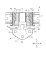
先ず、弾性マウント30の構成について説明する。図2から図6に示すように、弾性マウント30は、マウントブラケット31、外筒32、内筒33、及び、ゴムブッシュ(弾性部材)34から構成されている。但し、図3から図6においては、ゴムブッシュ34の表面には、ドットを付している。
First, the configuration of the
マウントブラケット31は、弾性マウント30の本体を構成しており、その下端がサイドメンバ12に固定されている。また、マウントブラケット31の上部には、円筒状をなす外筒32が固定されている。外筒32は、その中心軸が車幅方向に延在するように配置されており、この外筒32における車幅方向内側(パワーユニット15側)の端縁部には、フランジ部32aが形成されている。このフランジ部32aは、外筒32における車幅方向内側の外周縁部を、当該外筒32の径方向外側に向けて折り曲げたような部位となっている。
The
そして、外筒32の径方向内側には、円筒状をなす内筒33が配置されている。この内筒33は、その中心軸が、車幅方向に延在し、且つ、外筒32の中心軸と同軸状となるように設けられている。このとき、内筒33の軸方向長さは、外筒32の軸方向長さよりも短くなっており、その内筒33は、外筒32内における車幅方向外側に位置している。
A cylindrical
更に、外筒32と内筒33とは、ゴムブッシュ34を介して、弾性的に連結されている。このゴムブッシュ34は、外筒32の内周面と内筒33の外周面との間に加硫接着されており、このうち、外筒32の内周面においては、フランジ部32aの車幅方向内側表面まで接着されている。
Further, the
ここで、ゴムブッシュ34は、外側円筒部41、内側円筒部42、連結部43、及び、突出部44a,44b,44c,44dから構成されている。
Here, the
外側円筒部41は、外筒32の内周面全域を覆っており、内側円筒部42は、内筒33の外周面全域を覆っている。そして、2つの連結部43は、外筒32内の下部に配置されており、外側円筒部41と内側円筒部42とを径方向に連結している。なお、外側円筒部41の車幅方向内側部位は、フランジ部32aの車幅方向内側表面まで覆うよう構成されている。
The outer
また、突出部44a,44b,44c,44dは、外側円筒部41の内周面における上部、前部、下部、後部に配置されると共に、外側円筒部41から径方向内側に向けて(外筒32から径方向内側に向けて)突出するように形成されている。つまり、突出部44a,44b,44c,44dは、車両上下方向及び車両前後方向の振動に対応する位置に形成されている。なお、下部に位置する突出部44cは、連結部43間に配置されている。
The
更に、突出部44a,44b,44c,44dは、外筒32の軸方向(車幅方向)に延設されると共に、大突部51及び小突部52を有している。これらの大突部51と小突部52とは、車幅方向において隣接して形成されている。
Furthermore, the projecting
具体的に、大突部51は、外筒32内における車幅方向外側に配置され、内側円筒部42(内筒33)と径方向において対向しており、小突部52よりも径方向内側に向けて突出している。即ち、大突部51には、内側円筒部42が径方向内側から当接可能となっており、当該大突部51は、内筒33が径方向外側に向けて変位した際に、内側円筒部42と当接して、その内筒33の振動を吸収するように構成されている。そして、大突部51の径方向内側端面(頂面)と、内筒33の外周面との間の径方向距離は、D1(以下、距離D1と称す)となっている。
Specifically, the
これに対して、小突部52は、内筒33、内側円筒部42、及び、大突部51よりも車幅方向内側(パワーユニット15側)に配置されている。即ち、小突部52は、内筒33及び内側円筒部42と径方向において対向しない位置に配置されている。そして、小突部52の径方向内側端面(頂面)は、大突部51の径方向内側端面よりも径方向外側に配置されており、言い換えれば、小突部52における径方向内側への突出量は、大突部51における径方向内側への突出量よりも小さくなっている。
On the other hand, the
続いて、支持ブラケット20の構成について説明する。図2から図6に示すように、支持ブラケット20は、圧入軸部21、ユニット支持部22、及び、膨出部23から構成されている。
Next, the configuration of the
圧入軸部21は、弾性マウント30の内筒33内に圧入される部位となっており、内筒33の内周面に合致するような円形断面を有して、車幅方向に延在している。
The press-
ユニット支持部22は、パワーユニット15を固定支持する部位となっており、車両前後方向の幅が、車幅方向内側に向かうに従って漸次狭くなるような、平板三角形状をなしている。そして、ユニット支持部22における3つの角部には、ボルト孔22aが車両上下方向に貫通するように形成されており、これらのボルト孔22aには、ボルト(図示省略)が上方から下方に向けて挿入可能となっている。
The
これにより、上記ボルトを、ボルト孔22aを通じて、パワーユニット15(エンジン16)の上方から当該パワーユニット15に締結することにより、パワーユニット15をユニット支持部22の下面に密着させた状態で支持することができる。即ち、ボルト孔22aは、支持ブラケット20がパワーユニット15を支持するための支持点となっている。
Thus, the
また、ユニット支持部22における弾性マウント30と対向する車幅方向外側端部は、フランジ部32aの車幅方向内側表面と車幅方向において対向しており、その車幅方向外側端部における車両前後方向の幅寸法は、外筒32の直径より大きくなっている。そして、ユニット支持部22の車幅方向外側端部におけるフランジ部32aと対向する面は、支持ブラケット20の車幅方向外側への変位を規制する横ストッパ部22bを構成している。この横ストッパ部22bは、フランジ部32aの車幅方向内側表面、即ち、外側円筒部41の車幅方向内側部位に車幅方向内側から当接可能となっている。
Further, the vehicle width direction outer side end portion of the
膨出部23は、圧入軸部21とユニット支持部22との間の車幅方向中間部に配置されており、圧入軸部21よりも径方向外側に向けて膨出している。詳細には、膨出部23は、車両上下方向に長径となる楕円形断面を有しており、この楕円形断面は、圧入軸部21の円形断面よりも大きくなっている。
The bulging
更に、圧入軸部21が内筒33内に圧入されたときの膨出部23について説明すると、その圧入時における膨出部23は、その外周面が内側円筒部42の外周面よりも径方向外側に位置すると共に、突出部44a,44b,44c,44dの小突部52と径方向において対向している。即ち、膨出部23は、内筒33よりもパワーユニット15側に配置されると共に、内筒33の外周面よりも径方向外側に向けて膨出している。
Further, the bulging
そして、膨出部23の下部における内筒33よりも下方に向けて膨出した部分は、支持ブラケット20(パワーユニット15)の下方側への変位を規制する下ストッパ部23aを構成している。この下ストッパ部23aは、外側円筒部41の下部に形成された突出部44cの小突部52と径方向において対向しており、その小突部52に対して径方向内側(車両上方側)から当接可能となっている。
And the part which bulged below the
なお、下ストッパ部23aの径方向外側端面(最下面)と、小突部52の径方向内側端面(頂面)との間の径方向距離は、D2(以下、距離D2と称す)となっている。この距離D2は、距離D1よりも長くなるように設定されている。
The radial distance between the radially outer end surface (lowermost surface) of the
一方、膨出部23の上部における内筒33よりも上方に向けて膨出した部分は、支持ブラケット20(パワーユニット15)の上方側への変位を規制する上ストッパ部23bを構成している。この上ストッパ部23bは、外側円筒部41の上部に形成された突出部44aの小突部52と径方向において対向しており、その小突部52に対して径方向内側(車両下方側)から当接可能となっている。
On the other hand, the portion of the upper portion of the bulging
なお、上ストッパ部23bの径方向外側端面(最上面)と、小突部52の径方向内側端面(頂面)との間の径方向距離は、D3(以下、距離D3と称す)となっている。この距離D3は、距離D1よりも長くなるように設定されている。
The radial distance between the radially outer end surface (upper surface) of the
また、膨出部23の車両前後方向両側部における内筒33よりも車両前方側及び車両後方側に向けて膨出した部分は、支持ブラケット20(パワーユニット15)の車両前方側及び車両後方側への変位を規制する前後ストッパ部23cを構成している。更に、前後ストッパ部23cには、凹凸状をなす係止部23dが形成されている。この係止部23dは、前後ストッパ部23c(膨出部23)の外周面よりも凹んだ凹部と、この凹部よりも突出した凸部とを、車幅方向に交互に並べた構成となっている。そして、前後ストッパ部23c及び係止部23dは、外側円筒部41の前部及び後部に形成された突出部44b,44dの小突部52と径方向において対向しており、その小突部52に対して径方向内側(車両後方側及び車両前方側)から当接(係止)可能となっている。
Further, the portions bulged toward the vehicle front side and the vehicle rear side from the
なお、前後ストッパ部23cの径方向外側端面(前面及び後面)と、小突部52の径方向内側端面(頂面)との間の径方向距離は、D4(以下、距離D4と称す)となっている。この距離D4は、距離D1よりも長くなるように設定されている。
The radial distance between the radially outer end surfaces (front and rear surfaces) of the front and
つまり、支持ブラケット20は、内筒33よりもユニット支持部22側の位置において、小突部52と径方向において対向すると共に、内筒33の外周面よりも径方向外側に向けて膨出するストッパ部23a,23b,23cを有している。これにより、ストッパ部23a,23b,23cは、支持ブラケット20(パワーユニット15)の車両上下方向及び車両前後方向への変位を規制することが可能となっている。
That is, the
よって、上述した構成をなすことにより、車両走行時において、パワーユニット15に振動が発生すると、その振動は、支持ブラケット20を介して、弾性マウント30に伝達された後、当該弾性マウント30によって減衰される。つまり、弾性マウント30に伝達された振動は、ゴムブッシュ34の弾性変形によって3次元的に吸収される。更に、パワーユニット15が大きく変位して、支持ブラケット20に過大な振動が伝達された場合には、支持ブラケット20のストッパ部23a,23b,23cによって、当該支持ブラケット20の所定以上の変位、即ち、パワーユニット15の変位が規制される。
Therefore, with the configuration described above, when vibration is generated in the
詳細には、通常、支持ブラケット20から弾性マウント30に伝達される振動は、ゴムブッシュ34の連結部43が弾性変形することによって吸収される。そして、パワーユニット15が車両上下方向及び車両前後方向に大きく変位するような過大な振動が、支持ブラケット20に伝達された場合には、支持ブラケット20のストッパ部23a,23b,23cが、突出部44a,44b,44c,44dの小突部52に当接するため、パワーユニット15の変位が規制される。
Specifically, the vibration transmitted from the
例えば、悪路走行時のように、車両が上下方向に大きく揺れる状況においては、パワーユニット15が車両上下方向に大きく変位するため、支持ブラケット20から弾性マウント30に向けて、車両上下方向の過大な振動が伝達される。このような場合には、支持ブラケット20のストッパ部23a,23bが、突出部44a,44cの小突部52と当接すため、支持ブラケット20の車両上下方向への変位が規制される。
For example, when the vehicle is greatly shaken in the vertical direction, such as when traveling on a rough road, the
また、急発進及び急停止時等のように、車両が前後方向に大きく揺れる状況においては、パワーユニット15が車両前後方向に大きく変位するため、支持ブラケット20から弾性マウント30に向けて、車両前後方向の過大な振動が伝達される。このような場合には、支持ブラケット20の前後ストッパ部23cが、突出部44b,44dの小突部52と当接するため、支持ブラケット20の車両前後方向への変位が規制される。
Further, when the vehicle is greatly shaken in the front-rear direction, such as when suddenly starting and stopping, the
このように、車両上下方向及び車両前後方向の振動が過大となる場合には、ゴムブッシュ34が大きく変形して圧潰される前に、ストッパ部23a,23b,23cによって、パワーユニット15(支持ブラケット20)の変位を確実に規制することができる。これにより、ゴムブッシュ34の急激な弾性変形を抑制して、ゴムブッシュ34の負担を軽減させることができるので、ゴムブッシュ34の耐久性を向上させることができる。
Thus, when vibrations in the vehicle vertical direction and vehicle longitudinal direction become excessive, the power unit 15 (
このとき、ストッパ部23a,23b,23cは、内筒33よりもパワーユニット15側において、突出部44a,44b,44c,44dの小突部52に当接するため、過大な振動によって支持ブラケット20に作用する荷重を、支持点となるボルト孔22aに近い位置で受けることができる。これにより、支持ブラケット20に作用する曲げモーメントを低減させることができるので、当該支持ブラケット20の耐久性を向上させることができる。
At this time, since the
言い換えれば、支持ブラケット20の耐久性を向上させた分、当該支持ブラケット20の小型軽量化を図ることが可能となり、この結果、マウント装置全体の小型化を図ることができる。なお、外筒32の車幅方向内側端部は、フランジ部32aによって補強されているため、当該外筒32の変形を抑制することができる。
In other words, as the durability of the
また、突出部44a,44b,44c,44dを、突出量が大きい大突部51と、これに比べて突出量の小さい小突部52とから構成し、距離D1よりも距離D2,D3,D4を長くすることにより、ストッパ部23a,23b,23cが小突部52に当接して、支持ブラケット20の変位が規制される前に、内側円筒部42が大突部51に弾性支持されるため、支持ブラケット20への衝撃を緩和することができる。
The
更に、係止部23dを前後ストッパ部23に形成することにより、支持ブラケット20の弾性マウント30からの抜け防止を図ることができる。具体的に、車両が衝突すると、その衝撃荷重がパワーユニット15に作用して、当該パワーユニット15を支持する支持ブラケット20が、車両前後方向に振られながら、車幅方向内側に向けて引っ張られることになる。これに対して、係止部23dは、突出部44b,44dの小突部52に係止することで引き抜き抵抗となるため、圧入軸部21の内筒33からの抜け防止を図ることができる。
Further, by forming the locking
従って、本発明に係るマウント装置によれば、ストッパ部23a,23b,23cを、内筒33よりもパワーユニット15側に設けることにより、過大振動時の支持ブラケット20において、パワーユニット15を支持するための支持点(ボルト孔22a)により近い位置で、荷重を受けることができる。これにより、支持ブラケット20に作用する曲げモーメントを低減することができるので、支持ブラケット20の耐久性を向上させることができる。
Therefore, according to the mounting device according to the present invention, the
即ち、支持ブラケット20の耐久性を向上させることができた分、当該支持ブラケット20の小型軽量化を図ることができるため、マウント装置全体の小型化を図ることができる。しかも、ゴムブッシュ34の急激な弾性変形を抑制することができるので、当該ゴムブッシュ34の負担を軽減させることができる。これにより、ゴムブッシュ34の耐久性も向上させることができる。
That is, since the durability of the
また、突出部44a,44b,44c,44dを、大突部51及び小突部52とから構成すると共に、距離D1よりも距離D2,D3,D4を長くすることにより、支持ブラケット20への衝撃を緩和することができる。更に、外筒32の車幅方向内側端部に、フランジ部32aを形成することにより、外筒32の剛性を向上させることができる。これにより、ストッパ部23a,23b,23cが小突部52を大きな荷重で押圧しても、外筒32の破損を防止することができる。そして、前後ストッパ部23cに、係止部23dを形成することにより、車両衝突時における支持ブラケット20の弾性マウント30からの抜け防止を図ることができる。
In addition, the
本発明に係るマウント装置は、パワーユニットからマウント装置に伝達される振動を、効率的に吸収して、耐久性を向上させることができるため、自動車産業等において、極めて有益に利用することができる。 Since the mount device according to the present invention can efficiently absorb the vibration transmitted from the power unit to the mount device and improve the durability, it can be used extremely beneficially in the automobile industry and the like.
1 車体
15 パワーユニット
20 支持ブラケット
21 圧入軸部
22 ユニット支持部
22a ボルト孔
22b 横ストッパ部
23 膨出部
23a 下ストッパ部
23b 上ストッパ部
23c 前後ストッパ部
23d 係止部
30 弾性マウント
32 外筒
32a フランジ部
33 内筒
34 ゴムブッシュ
44a〜44d 突出部
51 大突部
52 小突部
DESCRIPTION OF SYMBOLS 1
Claims (4)
車体側に固定される外筒と、前記外筒の径方向内側に配置され、前記支持ブラケットが貫通する内筒と、前記外筒と前記内筒との間に介在される弾性部材とを有して、前記支持ブラケットを車体側に弾性支持する弾性マウントとを備えたマウント装置において、
前記弾性マウントは、
前記内筒の軸方向長さが前記外筒の軸方向長さよりも短く形成され、
前記支持ブラケットは、
前記内筒よりも前記パワーユニット側に配置されると共に、前記外筒の内周面と径方向において当接可能に対向しており、前記内筒の外周面よりも径方向外側に向けて膨出するストッパ部を有する
ことを特徴とするマウント装置。 A support bracket for supporting a power unit mounted on the vehicle;
An outer cylinder fixed to the vehicle body side, an inner cylinder that is disposed radially inside the outer cylinder and through which the support bracket passes, and an elastic member that is interposed between the outer cylinder and the inner cylinder. In the mounting device comprising an elastic mount that elastically supports the support bracket on the vehicle body side,
The elastic mount is
The axial length of the inner cylinder is formed shorter than the axial length of the outer cylinder,
The support bracket is
It is arranged on the power unit side with respect to the inner cylinder and faces the inner peripheral surface of the outer cylinder so as to be able to contact in the radial direction, and bulges outward in the radial direction from the outer peripheral surface of the inner cylinder. A mounting device characterized by having a stopper portion.
前記弾性部材は、
前記外筒の内周面から径方向内側に向けて突出し、前記ストッパ部と径方向において対向する小突部と、
前記外筒の内周面から径方向内側に向けて前記小突部よりも突出し、前記内筒と径方向において対向する大突部とを有し、
前記ストッパ部は、
当該ストッパ部の径方向外側端面と前記小突部の径方向内側端面との間の径方向距離が、前記内筒の外周面と前記大突部の径方向内側端面との間の径方向距離よりも、長くなるよう設定されている
ことを特徴とするマウント装置。 The mounting apparatus according to claim 1,
The elastic member is
A small protrusion that protrudes radially inward from the inner peripheral surface of the outer cylinder, and that faces the stopper portion in the radial direction;
It protrudes from the small protrusion toward the radially inner side from the inner peripheral surface of the outer cylinder, and has a large protrusion that faces the inner cylinder in the radial direction,
The stopper portion is
The radial distance between the radially outer end face of the stopper portion and the radially inner end face of the small protrusion is the radial distance between the outer peripheral face of the inner cylinder and the radially inner end face of the large protrusion. The mounting device is characterized in that it is set to be longer.
前記外筒における前記パワーユニット側の端縁部に、径方向外側に向けて屈曲するフランジ部を設ける
ことを特徴とするマウント装置。 The mounting device according to claim 1 or 2,
A mounting device, wherein a flange portion that is bent outward in the radial direction is provided at an end edge portion on the power unit side of the outer cylinder.
前記支持ブラケットは、
前記小突部と径方向において対向し、前記小突部に係止する係止部を有する
ことを特徴とするマウント装置。 In the mounting apparatus in any one of Claim 1 to 3,
The support bracket is
A mounting device comprising: a locking portion that faces the small protrusion in a radial direction and locks to the small protrusion.
Priority Applications (1)
| Application Number | Priority Date | Filing Date | Title |
|---|---|---|---|
| JP2015257026A JP6624377B2 (en) | 2015-12-28 | 2015-12-28 | Mounting device |
Applications Claiming Priority (1)
| Application Number | Priority Date | Filing Date | Title |
|---|---|---|---|
| JP2015257026A JP6624377B2 (en) | 2015-12-28 | 2015-12-28 | Mounting device |
Publications (2)
| Publication Number | Publication Date |
|---|---|
| JP2017120110A true JP2017120110A (en) | 2017-07-06 |
| JP6624377B2 JP6624377B2 (en) | 2019-12-25 |
Family
ID=59272098
Family Applications (1)
| Application Number | Title | Priority Date | Filing Date |
|---|---|---|---|
| JP2015257026A Active JP6624377B2 (en) | 2015-12-28 | 2015-12-28 | Mounting device |
Country Status (1)
| Country | Link |
|---|---|
| JP (1) | JP6624377B2 (en) |
Cited By (3)
| Publication number | Priority date | Publication date | Assignee | Title |
|---|---|---|---|---|
| JP2019049309A (en) * | 2017-09-08 | 2019-03-28 | 株式会社ブリヂストン | Vibration isolator and fitting member |
| CN110332152A (en) * | 2019-08-07 | 2019-10-15 | 江西书源科技有限公司 | A kind of shock-damping structure of water purifier water pump and shell |
| JP7033413B2 (en) | 2017-09-13 | 2022-03-10 | 株式会社ブリヂストン | Manufacturing method of anti-vibration device |
Citations (7)
| Publication number | Priority date | Publication date | Assignee | Title |
|---|---|---|---|---|
| JPS5763132U (en) * | 1980-10-03 | 1982-04-15 | ||
| JPS5765243U (en) * | 1980-10-03 | 1982-04-19 | ||
| JPS633532U (en) * | 1986-06-24 | 1988-01-11 | ||
| JPH10329555A (en) * | 1997-06-03 | 1998-12-15 | Yamakawa Ind Co Ltd | Vibration control device for power unit |
| JPH11153180A (en) * | 1997-11-25 | 1999-06-08 | Tokai Rubber Ind Ltd | Cylindrical vibration control assembly and its manufacture |
| JP2001105896A (en) * | 1999-10-05 | 2001-04-17 | Nissan Motor Co Ltd | Fitting structure of mount insulator and vibration control device |
| JP2011520066A (en) * | 2008-04-03 | 2011-07-14 | ザ・プルマン・カンパニー | Curved bushing with torsional slip |
-
2015
- 2015-12-28 JP JP2015257026A patent/JP6624377B2/en active Active
Patent Citations (7)
| Publication number | Priority date | Publication date | Assignee | Title |
|---|---|---|---|---|
| JPS5763132U (en) * | 1980-10-03 | 1982-04-15 | ||
| JPS5765243U (en) * | 1980-10-03 | 1982-04-19 | ||
| JPS633532U (en) * | 1986-06-24 | 1988-01-11 | ||
| JPH10329555A (en) * | 1997-06-03 | 1998-12-15 | Yamakawa Ind Co Ltd | Vibration control device for power unit |
| JPH11153180A (en) * | 1997-11-25 | 1999-06-08 | Tokai Rubber Ind Ltd | Cylindrical vibration control assembly and its manufacture |
| JP2001105896A (en) * | 1999-10-05 | 2001-04-17 | Nissan Motor Co Ltd | Fitting structure of mount insulator and vibration control device |
| JP2011520066A (en) * | 2008-04-03 | 2011-07-14 | ザ・プルマン・カンパニー | Curved bushing with torsional slip |
Cited By (3)
| Publication number | Priority date | Publication date | Assignee | Title |
|---|---|---|---|---|
| JP2019049309A (en) * | 2017-09-08 | 2019-03-28 | 株式会社ブリヂストン | Vibration isolator and fitting member |
| JP7033413B2 (en) | 2017-09-13 | 2022-03-10 | 株式会社ブリヂストン | Manufacturing method of anti-vibration device |
| CN110332152A (en) * | 2019-08-07 | 2019-10-15 | 江西书源科技有限公司 | A kind of shock-damping structure of water purifier water pump and shell |
Also Published As
| Publication number | Publication date |
|---|---|
| JP6624377B2 (en) | 2019-12-25 |
Similar Documents
| Publication | Publication Date | Title |
|---|---|---|
| JP6794950B2 (en) | Body structure | |
| JP2015009739A (en) | Shock absorber for vehicle, and shock absorbing structure of vehicle | |
| JP6532367B2 (en) | Tubular vibration control with bracket | |
| JP2015030375A (en) | Vehicle body front part structure of motor car | |
| US20140375081A1 (en) | Vehicle-body front structure | |
| JP2009227083A (en) | Power plant mounting structure on electric automobile | |
| WO2013051441A1 (en) | Steering column device | |
| CN109398057B (en) | Vehicle with a steering wheel | |
| CN110356215B (en) | Support structure for drive source | |
| JP2017120110A (en) | Mount device | |
| WO2014141929A1 (en) | Antivibration device | |
| US10414262B2 (en) | Power unit mount structure | |
| JP2013256266A (en) | Vehicle body front structure | |
| JP7115243B2 (en) | Support structure for automotive parts | |
| WO2014129099A1 (en) | Vibration isolator | |
| KR102437470B1 (en) | Rear Mounting Structure of Powertrain for Automotive | |
| KR20120045894A (en) | Sub-frame of vehicle | |
| US20130134641A1 (en) | Vibration isolator | |
| WO2019131512A1 (en) | Arrangement structure for vibration damping devices for electric automobiles | |
| KR20120126711A (en) | Power train mount for vehicles | |
| KR102361144B1 (en) | Mounting bush for vehicle and installation method thereof | |
| JP6366444B2 (en) | Torque rod anti-vibration structure | |
| JP6515948B2 (en) | Powertrain mounting device | |
| JP7463260B2 (en) | Cab Mount | |
| JP7047789B2 (en) | Bearing support bracket |
Legal Events
| Date | Code | Title | Description |
|---|---|---|---|
| A621 | Written request for application examination |
Free format text: JAPANESE INTERMEDIATE CODE: A621 Effective date: 20181130 |
|
| RD02 | Notification of acceptance of power of attorney |
Free format text: JAPANESE INTERMEDIATE CODE: A7422 Effective date: 20190529 |
|
| RD04 | Notification of resignation of power of attorney |
Free format text: JAPANESE INTERMEDIATE CODE: A7424 Effective date: 20190605 |
|
| RD04 | Notification of resignation of power of attorney |
Free format text: JAPANESE INTERMEDIATE CODE: A7424 Effective date: 20190530 |
|
| A977 | Report on retrieval |
Free format text: JAPANESE INTERMEDIATE CODE: A971007 Effective date: 20191017 |
|
| TRDD | Decision of grant or rejection written | ||
| A01 | Written decision to grant a patent or to grant a registration (utility model) |
Free format text: JAPANESE INTERMEDIATE CODE: A01 Effective date: 20191030 |
|
| A61 | First payment of annual fees (during grant procedure) |
Free format text: JAPANESE INTERMEDIATE CODE: A61 Effective date: 20191112 |
|
| R151 | Written notification of patent or utility model registration |
Ref document number: 6624377 Country of ref document: JP Free format text: JAPANESE INTERMEDIATE CODE: R151 |