JP2017114214A - Vehicle seat - Google Patents
Vehicle seat Download PDFInfo
- Publication number
- JP2017114214A JP2017114214A JP2015249817A JP2015249817A JP2017114214A JP 2017114214 A JP2017114214 A JP 2017114214A JP 2015249817 A JP2015249817 A JP 2015249817A JP 2015249817 A JP2015249817 A JP 2015249817A JP 2017114214 A JP2017114214 A JP 2017114214A
- Authority
- JP
- Japan
- Prior art keywords
- urethane pad
- seat
- air
- seated
- urethane
- Prior art date
- Legal status (The legal status is an assumption and is not a legal conclusion. Google has not performed a legal analysis and makes no representation as to the accuracy of the status listed.)
- Pending
Links
- JOYRKODLDBILNP-UHFFFAOYSA-N Ethyl urethane Chemical compound CCOC(N)=O JOYRKODLDBILNP-UHFFFAOYSA-N 0.000 claims abstract description 92
- 239000000463 material Substances 0.000 claims abstract description 20
- 239000000835 fiber Substances 0.000 claims description 40
- 230000035699 permeability Effects 0.000 claims description 11
- -1 3D mesh Substances 0.000 claims 1
- 210000000689 upper leg Anatomy 0.000 description 10
- 230000004048 modification Effects 0.000 description 4
- 238000012986 modification Methods 0.000 description 4
- 229920005992 thermoplastic resin Polymers 0.000 description 4
- 230000002542 deteriorative effect Effects 0.000 description 3
- 230000007423 decrease Effects 0.000 description 2
- 230000000694 effects Effects 0.000 description 2
- 230000006870 function Effects 0.000 description 2
- 238000013459 approach Methods 0.000 description 1
- 210000001217 buttock Anatomy 0.000 description 1
- 230000006866 deterioration Effects 0.000 description 1
- 210000003127 knee Anatomy 0.000 description 1
- 230000002093 peripheral effect Effects 0.000 description 1
- 229920005989 resin Polymers 0.000 description 1
- 239000011347 resin Substances 0.000 description 1
- 230000035807 sensation Effects 0.000 description 1
- 229920002725 thermoplastic elastomer Polymers 0.000 description 1
Images


Abstract
Description
本発明は、乗用車やトラックなどの車両用のシートに関する。 The present invention relates to a seat for a vehicle such as a passenger car or a truck.
車両用シートには、シートの裏面側から送風器でシートに着座している搭乗者の側に空気を送ったり、又は空気を引き込んで、シート表面の湿気や熱気を和らげる構成を備えているものがある。 Vehicle seats are equipped with a structure that relieves moisture and hot air on the seat surface by sending air from the back side of the seat to the side of the passenger seated on the seat with a blower, or drawing in air There is.
例えば、特開2004−73429号公報(特許文献1)には、シート本体の着座部位に熱可塑性エラストマ―樹脂などの熱可塑性樹脂からなる連続線状体を多数、それぞれループ状に曲がりくねらせ、かつ互いの接触部を融着させた立体網状構造体からなる網状クッション体を設け、シート本体のウレタンパット中に形成された、網状クッション体に連通する通気孔を形成した通気性シートが記載されている。 For example, in Japanese Patent Application Laid-Open No. 2004-73429 (Patent Document 1), a large number of continuous linear bodies made of a thermoplastic resin such as a thermoplastic elastomer resin are wound in a loop shape on the seating portion of the seat body, In addition, there is described a breathable sheet provided with a net-like cushion body made of a three-dimensional net-like structure in which contact portions are fused, and formed in a urethane pad of the sheet main body and having a vent hole communicating with the net-like cushion body. ing.
また、特開2012−115515号公報(特許文献2)には、シート本体の着座部の搭乗者の臀部が当たる部分をウレタンで形成し、搭乗者の大腿部が当たる部分を熱可塑性樹脂からなる連続線状体を、多数、それぞれループ状に曲がりくねらせ、かつ互いの接触部を融着させた立体網状構造体からなる立体網状クッション体で形成した通気性シートが記載されている。 Japanese Patent Laid-Open No. 2012-115515 (Patent Document 2) discloses that a portion of the seating portion of the seat body that contacts the buttock of the occupant is formed of urethane, and a portion of the seat body that contacts the thigh of the occupant is made of thermoplastic resin. There is described a breathable sheet formed of a three-dimensional network cushion body made of a three-dimensional network structure in which a large number of continuous linear bodies are wound in a loop shape, and the contact portions are fused together.
特許文献1又は2に記載されているような、熱可塑性樹脂からなる連続線状体で形成された繊維パッドは、通気性に優れ、空気は繊維パッド内を拡散して流れることができる。
The fiber pad formed by the continuous linear body which consists of a thermoplastic resin as described in
しかし、特許文献1に記載されている構成では、繊維パッドと送風器との間を、ウレタンパッドに形成した通気口で繋ぐ構成となっており、通気孔の断面が繊維パッドの断面と比べてかなり小さいので、通気孔から繊維パッドの側に送り出された空気は通気口の真上に流れて、通気孔の半径方向に離れた部分にはほとんど流れなくなってしまう。その結果、シート表面の湿気や熱気を和らげる効果が、通気孔の真上とその周辺に限られた局所的なものになってしまう。 However, in the configuration described in Patent Document 1, the fiber pad and the blower are connected by a vent formed in the urethane pad, and the cross section of the vent is compared with the cross section of the fiber pad. Since it is quite small, the air sent out from the air vent to the fiber pad side flows directly above the air vent and hardly flows in the radially separated portion of the air vent. As a result, the effect of relieving moisture and hot air on the sheet surface is locally limited to just above and around the vent hole.
また、特許文献2に記載されている構成では、搭乗者の大腿部が当たる比較的広い部分を熱可塑性樹脂からなる連続線状体からなる立体網状クッション体で形成しているが、この立体網状クッション体を介して積極的に空気を流通させるための送風器を備えておらず、シート表面の湿気や熱気を和らげる十分な効果を期待することができない。
Further, in the configuration described in
また、立体網状クッション体はウレタンパッドと比べて比較的柔らかく変形しやすい。そのため、特許文献2に記載されているように立体網状クッション体を搭乗者の大腿部が当たる比較的広い部分に配置すると、その上に搭乗者が着座した場合、周りのサポートがなくなって立体網状クッション体が大きく変形してしまう。その結果、搭乗者の座り心地を悪くするとともに、立体網状クッション体が一部密着して、空気の流れを悪くしてしまい可能性がある。
Further, the three-dimensional mesh cushion body is relatively soft and easily deformed as compared with the urethane pad. Therefore, as described in
本発明は、上記した従来技術の課題を解決して、搭乗者がシートに着座した状態でシート裏面側の送風器を作動させたときに、シート表面の側に形成した空気の流路全体に確実に空気が流れるようにした車両用シートを提供するものである。 The present invention solves the above-mentioned problems of the prior art, and when the air blower on the back side of the seat is operated while the passenger is seated on the seat, the entire air flow path formed on the seat surface side is provided. The present invention provides a vehicle seat that allows air to flow reliably.
上記した課題を解決するために、本発明では、シートクッションとシートバックとヘッドレストを備えた車両用シートを、シートクッションとシートバックとはそれぞれウレタンパッドを有し、それぞれのウレタンパッドには、搭乗者が着座する側の面から搭乗者が着座する側の面と反対側の面に通じる穴部が形成されており、それぞれのウレタンパッドに形成された穴部の内部にはウレタンパッドと比べて通気性を有する素材が充填されており、それぞれのウレタンパッドの搭乗者が着座する側の面には、穴部から延びる複数の溝が形成されており、それぞれのウレタンパッドの搭乗者が着座する側の面と反対の面の側には、通気性を有する素材が充填されている穴部を介してそれぞれのウレタンパッドの搭乗者が着座する側の面から空気を排気または吸気する送風器を備えて構成した。
また、上記した課題を解決するために、本発明では、シートクッションとシートバックとヘッドレストを備えた車両用シートを、シートクッションとシートバックとはそれぞれウレタンパッドを有し、シートクッションとシートバックの少なくとも一方のウレタンパッドには、搭乗者が着座する側の面から搭乗者が着座する側の面と反対側の面に通じる穴部が形成されており、ウレタンパッドに形成された穴部の内部にはウレタンパッドと比べて通気性を有する素材が充填されており、ウレタンパッドの搭乗者が着座する側の面には、搭乗者が着座する側の面に開口部を有して穴部から延びる溝であって、この溝の穴部から延びる方向に直角な方向の断面において開口部の幅寸法よりもウレタンパッドの内部の幅寸法の方が大きい溝が形成されており、ウレタンパッドの搭乗者が着座する側の面と反対の面の側には送風器を備えて構成した。
In order to solve the above-described problems, in the present invention, a seat for a vehicle including a seat cushion, a seat back, and a headrest is provided. The seat cushion and the seat back each have a urethane pad. A hole that leads from the surface on the side where the passenger is seated to the surface opposite to the surface on which the passenger is seated is formed, and compared to the urethane pad inside the hole formed in each urethane pad Filled with a breathable material, the surface of each urethane pad occupant seated is formed with a plurality of grooves extending from the hole, and each urethane pad occupant sits Air from the surface on the opposite side to the surface on which the passenger of each urethane pad is seated through a hole filled with a material having air permeability. And configured to include a blower for exhausting or intake.
In order to solve the above-described problems, in the present invention, a vehicle seat including a seat cushion, a seat back, and a headrest is provided. The seat cushion and the seat back each have a urethane pad, and the seat cushion and the seat back At least one urethane pad has a hole that leads from the surface on the side where the occupant is seated to the surface opposite to the surface on which the occupant is seated. Inside the hole formed in the urethane pad Is filled with a material that is breathable compared to the urethane pad, and the urethane pad occupant seated side has an opening on the surface on which the occupant sits, from the hole A groove extending in the cross section perpendicular to the direction extending from the hole of the groove, the width of the inside of the urethane pad being larger than the width of the opening. And it has, on the side of the opposite surface to the side surface of the occupant of the urethane pad is seated and configured with a blower.
本発明によれば、搭乗者がシートに着座した状態でシート裏面側の送風器を作動させたときに、シート表面の側に形成した空気の流路全体に確実に空気が流れるようにすることができるようになった。 According to the present invention, when the occupant operates the blower on the back side of the seat while sitting on the seat, the air surely flows through the entire air flow path formed on the seat surface side. Can now.
本発明は、車両用シートにおいて、着座した搭乗者の大腿部に接触する部分及び背部に接触する部分に、ウレタンパッドに替えて繊維パッドを設け、その周辺部に溝を設けることにより、搭乗者がシートに着座した状態でシート裏面側の送風器を作動させたときに、シート表面の側に形成した空気の流路全体に確実に空気が流れるようにすることができるようにしたものである。 The present invention provides a vehicle seat in which a fiber pad is provided instead of a urethane pad in a portion that contacts a thigh of a seated occupant and a portion that contacts a back portion, and a groove is provided in a peripheral portion thereof. When the person operates the blower on the back side of the seat while seated on the seat, the air can be surely flowed through the entire air flow path formed on the seat surface side. is there.
以下に、本発明の実施例を、図を用いて説明する。 Embodiments of the present invention will be described below with reference to the drawings.
図1は、本発明で対象とする車両用シート1の基本的な構成を示す。車両用シート1は、搭乗者が着座するシートクッション2、シートクッションに着座した搭乗者が背中をもたれ掛けるシートバック3、搭乗者の頭部を支えるヘッドレスト4を備えている。
FIG. 1 shows a basic configuration of a vehicle seat 1 targeted in the present invention. The vehicle seat 1 includes a
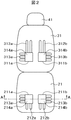
図2は、図1に示した車両用シート1の表面を覆うトリムカバーを外してウレタンパッドを露出させてシートバック3を倒した状態の車両用シート1の平面図である。 FIG. 2 is a plan view of the vehicle seat 1 in a state where the trim cover that covers the surface of the vehicle seat 1 shown in FIG.
シートクッション2の側のウレタンパッド21には、着座した搭乗者の大腿部が当たる部分に比較的大きな穴部211a及び211bが形成されており、穴部211a及び211bの内部には、繊維を編み状に絡めて形成した補助パッド部材(繊維パッド)214a、214bが充填されている。
The
また、繊維パッド214a、214bが充填されている穴部211a及び211bからは、着座した搭乗者に対して前方(膝の方向)に延びる溝部212a、212b及び側方(外側)に延びる溝部213a、213bが形成されている。この溝部212a、212b及び213a、213bの内部には繊維パッド214a、214bが充填されておらず、空洞になっている。
Further, from the
一方、シートバック3の側のウレタンパッド31には、着座した搭乗者の背部が当たる部分に比較的大きな穴部311a及び311bが形成されており、穴部311a及び311bの内部には、繊維を編み状に絡めて形成した補助パッド部材(繊維パッド)314a、314bが充填されている。
On the other hand, the
また、繊維パッド314a、314bが充填されている穴部311a及び311bからは、着座した搭乗者の背部の上方に延びている溝部312a、312b及び側方(外側)に延びる溝部313a、313bが形成されている。この溝部312a、312b及び313a、313bの内部には繊維パッド314a、314bが充填されておらず、空洞になっている。
Further, from the
図3Aには、図2におけるシートクッション2の側のウレタンパッド21におけるA−A断面を示す。穴部211a及び211bは、ウレタンパッド21を貫通して形成されている。また、ウレタンパッド21の裏面側(図3Aの下側)の穴部211a及び211bに対応する部分には、送風器215a,215bが、それぞれ取り付けられている。なお、図3Aにおいて、送風器215a,215bとウレタンパッド21とを接続する部材の表示を省略している。送風器215a,215bとしては、例えばシロッコファンを用いる。
FIG. 3A shows an AA cross section of the
図3Aに示した構成おいて、穴部211a及び211bの内部には繊維パッド214a,214bがそれぞれ充填されている。また、ウレタンパッド21の搭乗者が着座する面である上面側(図3Aの上側)には、穴部211aから外側に向かって溝部213aが形成されており,穴部211bから外側に向かって溝部213bが形成されている。
In the configuration shown in FIG. 3A,
シートクッション2の側をこのように構成したことにより、搭乗者が着座した状態で送風器215a及び215bを作動させると、送風器215a及び215bは、繊維パッド214a及び214bの搭乗者が着座した側から空気を吸い込んでウレタンパッド21の裏面側(図3Aの下側)から外部に排出する。この時、溝部212a、212b及び溝部213a、213bからも空気が吸い込まれて、シートクッション2に着座した搭乗者の大腿部の下、及びその周辺の比較的広い領域から空気が吸い込まれる。
By configuring the side of the
このように、シートクッション2に着座した搭乗者の大腿部の下、及びその周辺の比較的広い領域から空気を吸い込む構成としたことにより、穴部211a及び211bからだけ空気を吸い込む場合と比べてシート表面の比較的広い領域の湿気や熱気を和らげることができ、搭乗者の快適性を増すことができる。また、比較的広い領域から空気を吸い込むので、搭乗者が長時間着座し続けても、従来の構成と比べて比較的長い時間快適性を維持することができる。
Thus, by adopting a configuration in which air is sucked from a relatively wide area under and around the thigh of the occupant seated on the
なお、図2に示した構成では、繊維パッド214a、214bが充填されている穴部211a及び211bから着座した搭乗者に対して前方に延びる溝部212a、212b及び側方(外側)に延びる溝部213a、213bが形成されている例を示したが、穴部211a及び211bから着座した搭乗者に対して後方(臀部側)に延びる溝部や、穴部211a及び211bから着座した搭乗者に対して内側に延びる溝部を更に形成してもよい。
In the configuration shown in FIG. 2,
また、図3Aに示した構成において、穴部211a及び211bに対応してそれぞれ送風器215aおよび215bを取り付ける構成について説明したが、送風器を共通化してもよい。この場合、1台の送風器と穴部211a及び211bとの間にダクトに取り付け、このダクトを介して送風器で穴部211a及び211bから排気する。
Further, in the configuration shown in FIG. 3A, the configuration in which the
なお、穴部211a及び211bをシートクッション2の側のウレタンパッド21の搭乗者が着座する側の面から送風器215a、215bを取り付ける側の面まで同じ形状で形成する例を示したが、図3Bに示したように、送風器215a、215bを取り付ける側の部分2111a、2111bの断面がそれよりも上の部分と比べて小さくなるように形成してもよい。穴部211a及び211bの断面形状をこのように形成することにより、穴部211a及び211bの内部に充填した繊維パッド214a、214bが、穴部211a及び211bの下方、即ち送風器215a、215bの側にずれるのを防ぐことができる。
In addition, although the
更に、図3Aに示した穴部211a及び211bの形状に替えて、図3Cに示すように送風器215a、215bを取り付ける側の断面の径がウレタンパッド21の搭乗者が着座する側の断面の径よりも小さくなるように、テーパ状の断面の穴2110a、2110bにしてもよい。穴部2110a及び2110bの断面形状をこのように形成することにより、穴部2110a及び2110bの内部に充填した繊維パッド214a、214bが、穴部2110a及び2110bの下方、即ち送風器215a、215bの側にずれるのを防ぐことができる。シートバック3の側のウレタンパッド31の場合についても、図3Cと同様なことが適用できる。
Further, instead of the shape of the
図3A乃至図3Cには、シートクッション2の側のウレタンパッド21の構成を示したが、シートバック3の側のウレタンパッド31も同様な断面構成を有しており、穴部311a及び311bがウレタンパッド21を貫通して掲載され、その中に繊維パッド314a及び314bが充填されている。ウレタンパッド21の、穴部311a及び311bの裏面側(搭乗者が背をもたれる側と反対側の面)には、図3A乃至図3Cに示したのと同様に、送風器(図示せず)が取り付けられている。
3A to 3C show the configuration of the
シートバック3の側をこのように構成したことにより、搭乗者が着座してシートバック3に背をもたれたた状態で穴部311a及び311bの裏面側に取り付けた送風器を作動させると、送風器は、繊維パッド314a及び314bの搭乗者が着座した側から空気を吸い込んでウレタンパッド31の裏面側から外部に排出する。この時、溝部312a、312b及び溝部313a、313bからも空気が吸い込まれて、シートバック3に着座した搭乗者の背中が当たる部分及びその周辺の比較的広い領域から空気が吸い込まれる。
By configuring the side of the seat back 3 in this manner, when the occupant is seated and seated back on the seat back 3, the blower attached to the back side of the
なお、図2に示した構成では、繊維パッド314a、314bが充填されている穴部311a及び311bから着座した搭乗者に対して上方に延びる溝部312a、312b及び側方(外側)に延びる溝部313a、313bが形成されている例を示したが、穴部311a及び311bから着座した搭乗者に対して下方に延びる溝部や、穴部311a及び311bから着座した搭乗者に対して内側に延びる溝部を更に形成してもよい。
In the configuration shown in FIG. 2,
また、図3B及び図3Cで説明したことは、シートバック3の側のウレタンパッド31の場合についても同様に適用することができる。
3B and 3C can be similarly applied to the
なお、穴部211a及び211bに繊維パッド214a、214bを充填する例について説明したが、繊維パッド214a、214bに変えて、ウレタンパッド21や31と比べて通気性の良い素材、例えばウレタンパッドに微小な穴を多数形成して形成した通気性を有する材料や、3Dメッシュ、エアウィーブ(登録商標)、ブレスエアー(登録商標)などを用いてもよい。穴部311a及び311bに充填する材料についても同様である。
The example in which the
このように、シートバック3に背をもたれた搭乗者の背中及びその周辺の比較的広い領域から空気を吸い込む構成としたことにより、穴部211a及び211bからだけ空気を吸い込む場合と比べてシート表面の比較的広い領域の湿気や熱気を和らげることができ、搭乗者の快適性を増すことができる。また、比較的広い領域から空気を吸い込むので、搭乗者が長時間着座し続けても、従来の構成と比べて比較的長い時間快適性を維持することができる。
Thus, by adopting a configuration in which air is sucked from a relatively wide area around the back of the occupant seated back on the seat back 3 and the periphery thereof, the seat surface is compared with the case where air is sucked only from the
なお、上記した実施例では、シートバック3に着座した搭乗者の背中が当たる部分及びその周辺の比較的広い領域から送風器で空気が吸い込む場合について説明したが、これとは反対に、シートバック3に着座した搭乗者の背中が当たる部分及びその周辺の比較的広い領域に送風器から空気を吹き出すこともできる。 In the above-described embodiment, the case where the air is sucked by the blower from the portion where the back of the occupant seated on the seat back 3 hits and the relatively wide area around it is explained. It is also possible to blow out air from the blower to a portion where the back of the passenger seated in 3 hits and a relatively wide area around it.
また、上記した実施例では、シートクッション2とシートバック3の両方に穴部211a、211b及び311a、311bに繊維パッド214a、214b及び314a、314bを充填する例について説明したが、シートクッション2またはシートバック3の何れか一方だけに適用するようにしてもよい。
In the above-described embodiment, the example in which the
本発明の第2の実施例を、図4及び図5を用いて説明する。図4は、図1に示した車両用シート1の表面を覆うトリムカバーを外してウレタンパッドを露出させてシートバック3を倒した状態の車両用シート1の平面図である。 A second embodiment of the present invention will be described with reference to FIGS. FIG. 4 is a plan view of the vehicle seat 1 in a state in which the trim cover that covers the surface of the vehicle seat 1 shown in FIG.
第1の実施例と異なる点は、シートクッション2の側のウレタンパッド21に形成した溝212a、212b及び213a、213bの内部、及びシートバック3の側のウレタンパッド31に形成した溝312a、312b及び313a、313bの内部にもそれぞれ繊維パッド216a、216b及び316a、316bを充填した点である。
実施例1と同じ点については、重複を避けるために、説明を省略する。
The difference from the first embodiment is that the
About the same point as Example 1, explanation is omitted in order to avoid duplication.
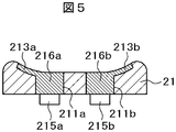
図4のB−B断面を図5に示す。実施例1の場合と同様に、穴部311a及び311bは、ウレタンパッド21を貫通して形成されている。また、ウレタンパッド21の裏面側(図3Aの下側)の穴部211a及び211bに対応する部分には、送風器215a,215bが、それぞれ取り付けられている。なお、図3Aにおいて、送風器215a,215bとウレタンパッド21とを接続する部材の表示を省略している。
FIG. 5 shows a BB cross section of FIG. As in the case of the first embodiment, the
図5に示した構成おいて、穴部211a及び211bの内部には繊維パッド214a,214bがそれぞれ充填されている。また、ウレタンパッド21の搭乗者が着座する面である上面側(図5の上側)には、穴部211aから外側に向かって溝部213aが形成されており,穴部211bから外側に向かって溝部213bが形成されている。
In the configuration shown in FIG. 5,
シートクッション2の側をこのように構成したことにより、搭乗者が着座した状態で送風器215a及び215bを作動させると、送風器215a及び215bは、繊維パッド214a及び214bの搭乗者が着座した側から空気を吸い込んでウレタンパッド21の裏面側(図5の下側)から外部に排出する。この時、溝部212a、212b及び溝部213a、213bからも空気が吸い込まれて、シートクッション2に着座した搭乗者の大腿部の下、及びその周辺の比較的広い領域から空気が吸い込まれる。
By configuring the side of the
このように、シートクッション2に着座した搭乗者の大腿部の下、及びその周辺の比較的広い領域から空気を吸い込む構成としたことにより、シート表面の比較的広い領域の湿気や熱気を和らげることができ、搭乗者の快適性を増すことができる。また、比較的広い領域から空気を吸い込むので、搭乗者が長時間着座し続けても、従来の構成と比べて比較的長い時間快適性を維持することができる。
In this way, by adopting a structure in which air is sucked from a relatively wide area under and around the thigh of the occupant seated on the
図5には、シートクッション2の側のウレタンパッド21の構成を示したが、シートバック3の側のウレタンパッド31も同様な断面構成を有している。すなわち、ウレタンパッド31には、穴部311a及び311bがウレタンパッド21を貫通して形成されている。また、穴部311aとそれから伸びている溝312a、313a、及び穴部311bとそれから延びている溝312b、313bの内部には繊維パッド316a及び316bが充填されている。ウレタンパッド31の、穴部311a及び311bの裏面側(搭乗者が背をもたれる側と反対側の面)には、図5に示したのと同様に、送風器(図示せず)が取り付けられている。
Although FIG. 5 shows the configuration of the
シートバック3の側をこのように構成したことにより、搭乗者が着座してシートバック3に背をもたれたた状態で穴部311a及び311bの裏面側に取り付けた送風器を作動させると、送風器は、繊維パッド316a及び316bの搭乗者が着座した側から空気を吸い込んでウレタンパッド31の裏面側から外部に排出する。これにより、シートバック3に着座した搭乗者の背中が当たる部分及びその周辺の比較的広い領域から空気が吸い込まれる。
By configuring the side of the seat back 3 in this manner, when the occupant is seated and seated back on the seat back 3, the blower attached to the back side of the
このように、シートバック3に背をもたれた搭乗者の背中及びその周辺の比較的広い領域から空気を吸い込む構成としたことにより、穴部311a及び311bからだけ空気を吸い込む場合と比べてシート表面の比較的広い領域の湿気や熱気を和らげることができ、搭乗者の快適性を増すことができる。また、比較的広い領域から空気を吸い込むので、搭乗者が長時間着座し続けても、従来の構成と比べて比較的長い時間快適性を維持することができる。
Thus, by adopting a configuration in which air is sucked in from a relatively wide area around the back of the passenger seated back on the seat back 3 and the periphery thereof, the seat surface is compared with the case where air is sucked only from the
なお、上記した実施例では、シートバック3に着座した搭乗者の背中が当たる部分及びその周辺の比較的広い領域から送風器で空気が吸い込む場合について説明したが、これとは反対に、シートバック3に着座した搭乗者の背中が当たる部分及びその周辺の比較的広い領域に送風器から空気を吹き出すこともできる。 In the above-described embodiment, the case where the air is sucked by the blower from the portion where the back of the occupant seated on the seat back 3 hits and the relatively wide area around it is explained. It is also possible to blow out air from the blower to a portion where the back of the passenger seated in 3 hits and a relatively wide area around it.
また、上記した実施例では、シートクッション2とシートバック3の両方の穴部211a、211b及び311a、311b並びに溝部に繊維パッド216a、216b及び316a、316bを充填する例について説明したが、シートクッション2またはシートバック3の何れか一方だけに適用するようにしてもよい。
In the above-described embodiment, an example in which the
更に、図5に示した構成において、穴部211a及び211bに対応してそれぞれ送風器215aおよび215bを取り付ける構成について説明したが、送風器を共通化してもよい。この場合、1台の送風器と穴部211a及び211bとの間にダクトに取り付け、このダクトを介して送風器で穴部211a及び211bから排気する。
Furthermore, in the structure shown in FIG. 5, although the structure which attaches the
本発明の第3の実施例を、図7乃至図9を用いて説明する。
実施例2において、図4に示したシートクッション2側のウレタンパッド21に形成された溝部212a、212b、213a、213b及び312a、312b、313a、313bは、溝の長手方向に対して直角な方向の断面は、同じ断面形状を有している。図6にその一例として、溝部212bの断面形状を示す。溝部212bは矩形状の断面形状を有している。
A third embodiment of the present invention will be described with reference to FIGS.
In Example 2, the
このような溝部が矩形状の断面形状の場合、搭乗者がシートクッション2に着座した時に、溝部の凹みを感じて座り心地が悪化してしまう恐れがある。
When such a groove portion has a rectangular cross-sectional shape, when the occupant sits on the
これに対して本実施例においては図7乃至図9に示すように、搭乗者が着座する面の側の溝部の開口部の寸法が、それよりも下側の部分の寸法と比べて小さくなるように形成した。すなわち、シートクッション2に着座した搭乗者に溝部の凹みを感じさせない程度の寸法となるように無負荷時の溝部の開口部の開口寸法を設定することにより、着座した搭乗者に凹みによる座り心地の悪化を防ぐようにした。
In contrast, in this embodiment, as shown in FIGS. 7 to 9, the size of the opening of the groove on the side of the surface on which the occupant sits is smaller than the size of the lower portion. Formed as follows. That is, by setting the opening size of the opening of the groove when no load is set so that the occupant seated on the
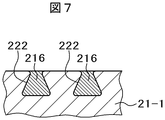
図7には、断面が台形に近い形状を有する溝部222を示す。図7において、ウレタンパッド21−1に形成された溝部222は、底の面が上側の開口部と比べて寸法が大きい台形に近い形状をしている。溝部222は、開口部がウレタンパッド21−1の内側に形成された溝部222の内部の空間部分よりも狭い断面形状を有している。溝部222の内部の空間部分には、繊維パッド216が充填されている。
FIG. 7 shows a
ここで、シートクッション2に搭乗者が着座すると、柔軟性のあるウレタンパッド21−1は搭乗者の体重で圧縮され変形し、溝部222も変形する。このとき、溝部222は、底部に対して上部(開口部)が狭い形状になっており、その断面において上部に近づくにつれて徐々に肉厚が薄くなるように形成されているので、搭乗者の体重を受けたときに開口部の幅が狭まる方向に大きく変形し易く、その結果開口部の寸法が狭くなる。これに対して、溝部222の底部は搭乗者が着座する前と寸法がほとんど変化しない。その結果、溝部222では、負荷がかかった状態においても空気が通る空間が確保されるので、溝部222の先端部まで空気を供給したり排気することができる。
Here, when a passenger sits on the
一方、溝部222の開口部は搭乗者の体重を受けたときに開口寸法(幅)が小さくなる方向に変形するが、この変形したときの開口寸法が着座した搭乗者に凹みを感じさせない程度の寸法となるように無負荷時の開口部の開口寸法を設定することにより、着座した搭乗者に凹みによる座り心地の悪化を防ぐことができる。
On the other hand, the opening of the
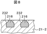
図8は、図7に対して、溝部231の断面形状を変えた例である。図8でウレタンパッド21―2に形成された溝部232の断面形状は、矩形状の空間の上部に、両側から徐々に肉厚が薄くなって中央に開口部が形成された形状である。すなわち、溝部232の上部に形成された開口部は、ウレタンパッド21―2の内部に形成された溝部232の空間部分よりも狭い断面形状を有している。このような溝部232の形状において、搭乗者がシートクッション2に着座した場合に、溝部232の上部に形成された開口部の幅が狭まる方向に大きく変形するのに対して、溝部232の底部は搭乗者が着座していない無負荷時と比べて寸法がほとんど変化しない。その結果、溝部232では、搭乗者が着座した状態においても空気が通る空間が確保されるので、溝部232の先端部まで空気を供給又は排気することができる。溝部232の内部の空間部分には、繊維パッド216が充填されている。
FIG. 8 is an example in which the cross-sectional shape of the groove portion 231 is changed with respect to FIG. The cross-sectional shape of the
また、溝部232の上部に形成された開口部は、負荷がかかると開口寸法(幅)が小さくなる方向に変形するが、この変形したときの開口寸法が着座した搭乗者に凹みを感じさせない程度の寸法となるように無負荷時の開口部の開口寸法を設定することにより、着座した搭乗者に凹みによる座り心地の悪化を防ぐことができる。
In addition, the opening formed in the upper part of the
図9は、図7に対して、溝部231の断面形状を変えた例である。図9の溝部242の断面形状は、円形断面の空間の上部に、両側から徐々に肉厚が薄くなって中央に開口部が形成された形状である。すなわち、溝部242は、上部に形成された開口部がウレタンパッド21―3の内側の溝部242の内部の空間部分の一番広い部分よりも狭い断面形状を有している。この図9に示した溝部242においても、搭乗者がシートクッション2に着座した場合に、開口部の幅が狭まる方向に大きく変形するのに対して、溝部242の底部は搭乗者がシートクッション2に着座していない無負荷時と比べて寸法がほとんど変化しない。その結果、溝部242では、搭乗者がシートクッション2に着座して負荷がかかった状態においても空気が通る空間が確保されるので、溝部242の先端部まで空気を供給又は排気することができる。溝部242の内部の空間部分には、繊維パッド216が充填されている。
FIG. 9 is an example in which the cross-sectional shape of the groove portion 231 is changed with respect to FIG. The cross-sectional shape of the
また、溝部242の開口部は負荷がかかると開口寸法(幅)が小さくなる方向に変形するが、この変形したときの開口寸法が着座した搭乗者に凹みを感じさせない程度の寸法となるように無負荷時の開口部の開口寸法を設定することにより、着座した搭乗者に凹みによる座り心地の悪化を防ぐことができる。
Further, the opening of the
本実施例によれば、例えば図7に示した構成において、ウレタンパッド21−1に形成した溝部222の断面形状において、溝部222の上部の搭乗者が着座する側に設けた開口部の断面形状を、外側から開口部の中心に向かって徐々に肉厚が薄くなるような形状としたことにより、シートクッション2に着座した搭乗者の大腿部の下、及びその周辺の比較的広い領域から空気を吸い込むことが可能になる。このような構成としたことにより、シート表面の比較的広い領域の湿気や熱気を和らげることができ、搭乗者の快適性を増すことができる。また、比較的広い領域から空気を吸い込むので、搭乗者が長時間着座し続けても、従来の構成と比べて比較的長い時間快適性を維持することができる。
According to the present embodiment, for example, in the configuration shown in FIG. 7, in the cross-sectional shape of the
また、溝部222,232,242の変形の程度は、負荷、即ち着座した搭搭乗者の体重や着座位置などにより変わり、大きな負荷がかかった場所では溝部222,232,242は大きく変形してそれぞれの開口部の幅が狭くなり、負荷が小さい場所では溝部222,232,242の変形が少なくそれぞれの開口部の開口寸法はあまり狭くはならない。これに伴って、それぞれの開口部から吹き出す又は吸い込む空気の量に分布が生じ、大きな負荷がかかっている場所では開口部からの空気の吹き出し量又は吸い込み量が少なく、負荷が比較的小さい場所では開口部からの空気の吹き出し量又は吸い込み量が多くなる。
The degree of deformation of the
このように、負荷が比較的小さい場所での開口部からの空気の吹き出し量又は吸い込み量が多くなることにより、着座した搭乗者の清涼感を増すことができ、体感を良くすることができる。 As described above, the amount of air blown out or sucked in from the opening in a place where the load is relatively small increases, so that the coolness of the seated occupant can be increased and the bodily sensation can be improved.
また、大きな負荷がかかって溝部222,232,又は242の断面が大きく変形した場所であっても、上述したように空気の通る空間が確保されているので、送風器215aまたは215bから送られてきた空気は、大きな抵抗がなく溝部222,232,又は242の全体に行き亘らせることができる。また、送風器215aまたは215bで溝部222,232,又は242から空気を吸い込む場合も、大きな抵抗がなく吸い込むことができる。そのため、送風機214a及び215bとして、シロッコファンに変えて軸流ファンを用いても、溝部222,232,又は242の全体に亘って十分な風量を確保することができる。
In addition, even if it is a place where a large load is applied and the cross section of the
本実施例では、実施例2の場合と同様に、溝部222,232,又は242の内部の空間部分に繊維パッド216を充填させた状態の例で説明したが、実施例1で説明したように、溝部222,232,又は242の内部の空間部分に繊維パッド216を充填させない場合にも適用できる。
In the present embodiment, as in the case of the second embodiment, an example in which the
以上、本発明者によってなされた発明を実施例に基づき具体的に説明したが、本発明は前記実施例に限定されるものではなく、その要旨を逸脱しない範囲で種々変更可能であることは言うまでもない。すなわち、上記実施例で説明した構成の一部をそれと等価な機能を有する手段で置き換えたものも、または、実質的でない機能の一部を省略したものも本発明に含まれる。 As mentioned above, although the invention made by the present inventor has been specifically described based on the embodiments, it is needless to say that the present invention is not limited to the above embodiments and can be variously modified without departing from the gist thereof. Yes. That is, the present invention includes a configuration in which a part of the configuration described in the above embodiment is replaced with a unit having a function equivalent to that, or a configuration in which a part of a function that is not substantial is omitted.
1・・・車両用シート 2・・・シートクッション 3・・・シートバック 4・・・ヘッドレスト 21,21−1,21−2,21−3、31・・・ウレタンパッド 211a、211b、311a、311b・・・穴部 212a、212b、213a、213b、312a、312b、313a、313b・・・溝部 214a、214b、216a、216b・・・繊維パッド 216・・・繊維パッド 222,232,242・・・溝部
DESCRIPTION OF SYMBOLS 1 ...
Claims (8)
前記シートクッションとシートバックとはそれぞれウレタンパッドを有し、
前記それぞれのウレタンパッドには、搭乗者が着座する側の面から前記搭乗者が着座する側の面と反対側の面に通じる穴部が形成されており、
前記それぞれのウレタンパッドに形成された穴部の内部には前記ウレタンパッドと比べて通気性を有する素材が充填されており、
前記それぞれのウレタンパッドの前記搭乗者が着座する側の面には、前記穴部から延びる複数の溝が形成されており、
前記それぞれのウレタンパッドの前記搭乗者が着座する側の面と反対の面の側には、前記通気性を有する素材が充填されている前記穴部を介して前記それぞれのウレタンパッドの前記搭乗者が着座する側の面から空気を排気または吸気する送風器を備えたことを特徴とする車両用シート。 A vehicle seat having a seat cushion, a seat back, and a headrest,
Each of the seat cushion and the seat back has a urethane pad,
Each of the urethane pads is formed with a hole that leads from a surface on the side where the occupant is seated to a surface opposite to the surface on which the occupant is seated,
The inside of the hole formed in each of the urethane pads is filled with a material having air permeability as compared with the urethane pad,
A plurality of grooves extending from the holes are formed on the surface of each urethane pad on the side on which the passenger sits,
The passengers of the respective urethane pads are inserted through the holes filled with the air-permeable material on the surface of the respective urethane pads opposite to the surface on which the passengers sit. A vehicle seat comprising a blower that exhausts or sucks air from a surface on the side on which the seat is seated.
前記シートクッションとシートバックとはそれぞれウレタンパッドを有し、
前記シートクッションとシートバックの少なくとも一方のウレタンパッドには、搭乗者が着座する側の面から前記搭乗者が着座する側の面と反対側の面に通じる穴部が形成されており、
前記ウレタンパッドに形成された穴部の内部には前記ウレタンパッドと比べて通気性を有する素材が充填されており、
前記ウレタンパッドの前記搭乗者が着座する側の面には、前記搭乗者が着座する側の面に開口部を有して前記穴部から延びる溝であって、前記溝の前記穴部から延びる方向に直角な方向の断面において前記開口部の幅寸法よりも前記ウレタンパッドの内部の幅寸法の方が大きい溝が形成されており、
前記それぞれのウレタンパッドの前記搭乗者が着座する側の面と反対の面の側には送風器を備えたことを特徴とする車両用シート。 A vehicle seat having a seat cushion, a seat back, and a headrest,
Each of the seat cushion and the seat back has a urethane pad,
The urethane pad of at least one of the seat cushion and the seat back is formed with a hole portion that leads from the surface on the side where the occupant is seated to the surface opposite to the surface on which the occupant is seated,
The inside of the hole formed in the urethane pad is filled with a material having air permeability compared to the urethane pad,
A surface of the urethane pad on which the occupant sits has a groove extending from the hole having an opening on the surface on which the occupant is seated, and extending from the hole of the groove A groove having a larger width dimension inside the urethane pad than a width dimension of the opening is formed in a cross section in a direction perpendicular to the direction,
A vehicle seat comprising a blower on a surface of each of the urethane pads opposite to a surface on which the passenger is seated.
Priority Applications (4)
| Application Number | Priority Date | Filing Date | Title |
|---|---|---|---|
| JP2015249817A JP2017114214A (en) | 2015-12-22 | 2015-12-22 | Vehicle seat |
| US15/781,138 US11072266B2 (en) | 2015-12-22 | 2016-12-09 | Vehicle seat |
| CN201680072668.4A CN108367695A (en) | 2015-12-22 | 2016-12-09 | It is vehicle seat used |
| PCT/JP2016/086748 WO2017110529A1 (en) | 2015-12-22 | 2016-12-09 | Vehicle seat |
Applications Claiming Priority (1)
| Application Number | Priority Date | Filing Date | Title |
|---|---|---|---|
| JP2015249817A JP2017114214A (en) | 2015-12-22 | 2015-12-22 | Vehicle seat |
Publications (2)
| Publication Number | Publication Date |
|---|---|
| JP2017114214A true JP2017114214A (en) | 2017-06-29 |
| JP2017114214A5 JP2017114214A5 (en) | 2018-09-20 |
Family
ID=59233260
Family Applications (1)
| Application Number | Title | Priority Date | Filing Date |
|---|---|---|---|
| JP2015249817A Pending JP2017114214A (en) | 2015-12-22 | 2015-12-22 | Vehicle seat |
Country Status (1)
| Country | Link |
|---|---|
| JP (1) | JP2017114214A (en) |
Cited By (1)
| Publication number | Priority date | Publication date | Assignee | Title |
|---|---|---|---|---|
| JP2019182026A (en) * | 2018-04-03 | 2019-10-24 | 株式会社デンソー | Seat air conditioner and wind distribution seat |
Citations (3)
| Publication number | Priority date | Publication date | Assignee | Title |
|---|---|---|---|---|
| JPH11137371A (en) * | 1997-11-10 | 1999-05-25 | Aisin Seiki Co Ltd | Air permeable seat device |
| JP2004073429A (en) * | 2002-08-15 | 2004-03-11 | Nhk Spring Co Ltd | Air permeable seat |
| JP2012228333A (en) * | 2011-04-26 | 2012-11-22 | Tachi S Co Ltd | Air permeable seat structure |
-
2015
- 2015-12-22 JP JP2015249817A patent/JP2017114214A/en active Pending
Patent Citations (3)
| Publication number | Priority date | Publication date | Assignee | Title |
|---|---|---|---|---|
| JPH11137371A (en) * | 1997-11-10 | 1999-05-25 | Aisin Seiki Co Ltd | Air permeable seat device |
| JP2004073429A (en) * | 2002-08-15 | 2004-03-11 | Nhk Spring Co Ltd | Air permeable seat |
| JP2012228333A (en) * | 2011-04-26 | 2012-11-22 | Tachi S Co Ltd | Air permeable seat structure |
Cited By (1)
| Publication number | Priority date | Publication date | Assignee | Title |
|---|---|---|---|---|
| JP2019182026A (en) * | 2018-04-03 | 2019-10-24 | 株式会社デンソー | Seat air conditioner and wind distribution seat |
Similar Documents
| Publication | Publication Date | Title |
|---|---|---|
| WO2017110529A1 (en) | Vehicle seat | |
| US6619737B2 (en) | Seat module for a vehicle seat which can be actively ventilated | |
| US6808230B2 (en) | Seat module for a vehicle seat which can be actively ventilated and method of making same | |
| JP6480215B2 (en) | Vehicle seat | |
| JP2005287532A (en) | Car seat | |
| JP6423732B2 (en) | Vehicle seat | |
| JP5959812B2 (en) | Vehicle seat | |
| JP2007520288A (en) | Vehicle seat | |
| JP2015107744A (en) | Air permeable seat | |
| US20180065525A1 (en) | Vehicle seat | |
| JP7262935B2 (en) | vehicle seat | |
| JP7280043B2 (en) | seat pad | |
| JP2017114214A (en) | Vehicle seat | |
| JP2019162948A (en) | Vehicular seat | |
| JP2018038810A (en) | seat | |
| KR101683484B1 (en) | A ventilated pad for vehicle | |
| JP6130330B2 (en) | Sheet | |
| JP5176588B2 (en) | Sheet blower | |
| JP2017154680A (en) | Vehicle seat | |
| JP6665807B2 (en) | Vehicle seat | |
| JP2017065638A (en) | Vehicle seat | |
| JP5994674B2 (en) | Vehicle seat | |
| JP2004166812A (en) | Seat | |
| JP2008037232A (en) | Ventilation type child seat | |
| KR20170027231A (en) | Vehicle Seat For Cooling And Heating |
Legal Events
| Date | Code | Title | Description |
|---|---|---|---|
| A521 | Request for written amendment filed |
Free format text: JAPANESE INTERMEDIATE CODE: A523 Effective date: 20180806 |
|
| A621 | Written request for application examination |
Free format text: JAPANESE INTERMEDIATE CODE: A621 Effective date: 20180806 |
|
| A131 | Notification of reasons for refusal |
Free format text: JAPANESE INTERMEDIATE CODE: A131 Effective date: 20190625 |
|
| A521 | Request for written amendment filed |
Free format text: JAPANESE INTERMEDIATE CODE: A523 Effective date: 20190725 |
|
| A02 | Decision of refusal |
Free format text: JAPANESE INTERMEDIATE CODE: A02 Effective date: 20191105 |