JP2017107697A - Light source unit and lighting fixture - Google Patents

Light source unit and lighting fixture Download PDF

Info

Publication number
JP2017107697A
JP2017107697A JP2015239542A JP2015239542A JP2017107697A JP 2017107697 A JP2017107697 A JP 2017107697A JP 2015239542 A JP2015239542 A JP 2015239542A JP 2015239542 A JP2015239542 A JP 2015239542A JP 2017107697 A JP2017107697 A JP 2017107697A
Authority
JP
Japan
Prior art keywords
light source
source unit
pair
substrate
cover
Prior art date
Legal status (The legal status is an assumption and is not a legal conclusion. Google has not performed a legal analysis and makes no representation as to the accuracy of the status listed.)
Pending
Application number
JP2015239542A
Other languages
Japanese (ja)
Inventor
山川 守
Mamoru Yamakawa
守 山川
Current Assignee (The listed assignees may be inaccurate. Google has not performed a legal analysis and makes no representation or warranty as to the accuracy of the list.)
Panasonic Intellectual Property Management Co Ltd
Original Assignee
Panasonic Intellectual Property Management Co Ltd
Priority date (The priority date is an assumption and is not a legal conclusion. Google has not performed a legal analysis and makes no representation as to the accuracy of the date listed.)
Filing date
Publication date
Application filed by Panasonic Intellectual Property Management Co Ltd filed Critical Panasonic Intellectual Property Management Co Ltd
Priority to JP2015239542A priority Critical patent/JP2017107697A/en
Publication of JP2017107697A publication Critical patent/JP2017107697A/en
Pending legal-status Critical Current

Links

Images

Abstract

PROBLEM TO BE SOLVED: To provide a light source unit and a lighting fixture capable of achieving weight saving and improvement in work efficiency.SOLUTION: A light source unit 1 includes: light source modules 2; connection members 3; and a cover 4 for accommodating the light source modules 2 connected by the connection members 3. At a substrate 21, insertion holes 23 penetrating in a thickness direction are provided near both ends in the direction connected by the connection members 3. The cover 4 is formed so that the plurality of light source modules 2 connected by the connection members 3 are accommodated being arrayed side by side in the longer direction. The connection member 3 has a main part 31 formed in a tabular shape, and a pair of claw parts 32 protruding from one surface of the main part. Each of the pair of claw parts 32 is inserted in each of the insertion holes 23 provided at each of the two substrates 21 adjacent to each other.SELECTED DRAWING: Figure 1

Description

本発明は、光源ユニットおよび照明器具に関する。   The present invention relates to a light source unit and a lighting fixture.

従来例として、特許文献1に記載の照明器具を例示する。特許文献1に記載の照明器具は、器具本体と、器具本体に取り付け可能なフレームと、光源である複数のLEDが一列に実装された複数の基板とを備える。フレームは、底面板を備える。底面板の表面側には、複数の基板が長手方向に並べられており、複数の基板のそれぞれは、底面板にねじによって固定されている。   As a conventional example, the lighting fixture described in Patent Document 1 is illustrated. The lighting fixture described in Patent Literature 1 includes a fixture main body, a frame that can be attached to the fixture main body, and a plurality of substrates on which a plurality of LEDs that are light sources are mounted in a row. The frame includes a bottom plate. A plurality of substrates are arranged in the longitudinal direction on the surface side of the bottom plate, and each of the plurality of substrates is fixed to the bottom plate with screws.

特開2010−277924号公報JP 2010-277924 A

ところで、特許文献1に記載の照明器具において、フレームの底面板は、器具本体の底面と略一致する面積に形成されており、照明器具の重量の増加の要因となっていた。また、複数の基板のそれぞれには両端付近にねじ挿通孔が設けられており、作業者は、複数の基板をフレームに固定するために基板の一つ一つをねじ止めする必要がある。したがって、作業効率が悪かった。   By the way, in the lighting fixture described in Patent Document 1, the bottom plate of the frame is formed in an area substantially coinciding with the bottom surface of the fixture main body, which causes an increase in the weight of the lighting fixture. Each of the plurality of substrates is provided with screw insertion holes near both ends, and the operator needs to screw each of the substrates in order to fix the plurality of substrates to the frame. Therefore, work efficiency was bad.

本発明は、上記事由に鑑みてなされており、軽量化、および作業効率の向上を図ることができる光源ユニットおよび照明器具を提供することを目的とする。   This invention is made | formed in view of the said reason, and aims at providing the light source unit and lighting fixture which can aim at weight reduction and the improvement of work efficiency.

本発明の光源ユニットは、光源モジュールと、1乃至複数の連結部材と、前記1乃至複数の連結部材で連結される前記光源モジュールを収容するカバーとを備え、前記複数の光源モジュールのそれぞれは、板状に形成される基板と、前記基板の一面に実装される複数の固体発光素子とを有し、前記基板には、厚み方向に貫通される1乃至複数の挿通孔が前記1乃至複数の連結部材によって連結される方向の両端付近に設けられ、前記カバーは、長尺の箱状に形成され、かつ前記1乃至複数の連結部材で連結されている前記複数の光源モジュールが長手方向に並んで収容されるように形成され、前記1乃至複数の連結部材は、板状に形成される主部と、前記主部の一面から突出する一対の爪部とを有し、前記一対の爪部のそれぞれは、隣り合う2つの前記基板のそれぞれに設けられる前記挿通孔のそれぞれに挿通されていることを特徴とする。   The light source unit of the present invention includes a light source module, one or more connecting members, and a cover that houses the light source module connected by the one or more connecting members, and each of the plurality of light source modules includes: A substrate formed in a plate shape, and a plurality of solid state light emitting devices mounted on one surface of the substrate, wherein the substrate has one or more insertion holes penetrating in a thickness direction. Provided near both ends in the direction connected by the connecting member, the cover is formed in a long box shape, and the plurality of light source modules connected by the one or more connecting members are arranged in the longitudinal direction. The one or more connecting members have a main part formed in a plate shape and a pair of claw parts protruding from one surface of the main part, and the pair of claw parts Each of the next Characterized in that it is inserted into each of the insertion holes provided in respective One of the substrate.

本発明の照明器具は、上述の光源ユニットと、前記光源ユニットを保持する器具本体とを備えることを特徴とする。   The lighting fixture of this invention is equipped with the above-mentioned light source unit and the fixture main body holding the said light source unit, It is characterized by the above-mentioned.

本発明の光源ユニットおよび照明器具は、上記事由に鑑みてなされており、軽量化、および作業効率の向上を図ることができるという効果がある。   The light source unit and the lighting fixture of the present invention have been made in view of the above-described reasons, and are effective in reducing the weight and improving the work efficiency.

本発明の実施形態に係る光源ユニットを示す分解斜視図である。It is a disassembled perspective view which shows the light source unit which concerns on embodiment of this invention. 実施形態に係る光源ユニットを示す部分拡大図である。It is the elements on larger scale which show the light source unit which concerns on embodiment. 実施形態に係る連結部材を示す斜視図である。It is a perspective view which shows the connection member which concerns on embodiment. 実施形態に係る光源ユニットを示す断面図である。It is sectional drawing which shows the light source unit which concerns on embodiment. 実施形態の変形例1に係る連結部材を示す斜視図である。It is a perspective view which shows the connection member which concerns on the modification 1 of embodiment. 実施形態の変形例2に係る連結部材を示す斜視図である。It is a perspective view which shows the connection member which concerns on the modification 2 of embodiment. 実施形態の変形例2に係る光源ユニットを示し、図7Aは平面図、図7Bは正面図である。The light source unit which concerns on the modification 2 of embodiment is shown, FIG. 7A is a top view, FIG. 7B is a front view. 実施形態に係る照明器具を示し、図8Aは正面図、図8Bは横断面図である。The lighting fixture which concerns on embodiment is shown, FIG. 8A is a front view, FIG. 8B is a cross-sectional view.

以下の実施形態は、光源ユニットおよび照明器具に関し、特に、複数の光源モジュールを有する光源ユニットと、光源ユニットを保持する照明器具に関する。   The following embodiments relate to a light source unit and a lighting fixture, and more particularly, to a light source unit having a plurality of light source modules and a lighting fixture holding the light source unit.

以下、光源ユニットおよび照明器具の実施形態について、図面を参照して詳細に説明する。なお、以下の実施形態において、光源ユニット1および光源ユニット1を用いた壁埋込型の照明器具10について例示する。ただし、壁埋込型の照明器具10は一例に過ぎず、光源ユニット1は、壁埋込型の照明器具10以外の照明器具にも用いることができる。   Hereinafter, embodiments of a light source unit and a lighting fixture will be described in detail with reference to the drawings. In the following embodiment, a light source unit 1 and a wall-embedded lighting fixture 10 using the light source unit 1 are illustrated. However, the wall-embedded lighting fixture 10 is merely an example, and the light source unit 1 can be used for lighting fixtures other than the wall-embedded lighting fixture 10.

本実施形態の光源ユニット1について、図1〜図4を参照して説明する。本実施形態の光源ユニット1は、図1に示すように、複数の光源モジュール2と、1乃至複数の連結部材3と、1乃至複数の連結部材3で連結される複数の光源モジュール2を収容するカバー4とを備える。   The light source unit 1 of this embodiment is demonstrated with reference to FIGS. As shown in FIG. 1, the light source unit 1 of the present embodiment accommodates a plurality of light source modules 2, one to a plurality of connecting members 3, and a plurality of light source modules 2 connected by one to a plurality of connecting members 3. The cover 4 is provided.

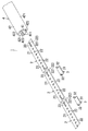
複数の光源モジュール2のそれぞれは、長尺な矩形板状に形成される基板21と、基板21の一面(以下、表面とする)に実装される複数の固体発光素子(例えば、発光ダイオード)22とを有する。複数の発光ダイオード22は、基板21の短手方向の中央に、長手方向に沿って等間隔に並べられて実装される。なお、図2に示すように、基板21に実装される複数の発光ダイオード22の間隔を距離d1とする。また、基板21の両端のそれぞれに最も近い位置に実装されている2つの発光ダイオード22を発光ダイオード221とする。さらに、隣り合う2つの基板21のうち、一方の基板21の一端に実装される発光ダイオード221と、他方の基板21の他端に実装される発光ダイオード221との距離をd2とする。   Each of the plurality of light source modules 2 includes a substrate 21 formed in a long rectangular plate shape, and a plurality of solid light emitting elements (for example, light emitting diodes) 22 mounted on one surface (hereinafter referred to as a surface) of the substrate 21. And have. The plurality of light emitting diodes 22 are mounted at equal intervals along the longitudinal direction in the center of the substrate 21 in the short direction. As shown in FIG. 2, the distance between the plurality of light emitting diodes 22 mounted on the substrate 21 is a distance d1. Two light emitting diodes 22 mounted at positions closest to both ends of the substrate 21 are referred to as light emitting diodes 221. Further, of two adjacent substrates 21, the distance between the light emitting diode 221 mounted on one end of one substrate 21 and the light emitting diode 221 mounted on the other end of the other substrate 21 is d2.

ところで、隣り合う2つの基板の間には所定の隙間が設けられる。つまり、隣り合う2つの基板21の隙間に影が生じてしまい、基板21の両端付近の輝度が弱くなってしまうことがある。そこで、輝度のばらつきを抑制するために、本実施形態において、距離d2が距離d1よりも短くなるように構成されている。   By the way, a predetermined gap is provided between two adjacent substrates. That is, a shadow is generated in the gap between two adjacent substrates 21, and the luminance near both ends of the substrate 21 may be weakened. Therefore, in order to suppress variations in luminance, in the present embodiment, the distance d2 is configured to be shorter than the distance d1.

なお、本実施形態において、隣り合う2つの基板21の距離を距離d21とする。また、固体発光素子は、発光ダイオード22,221以外の固体発光素子、例えば有機エレクトロルミネセンス素子であっても構わない。さらに、複数の固体発光素子(発光ダイオード)22,221の基板21上の配置は、本実施形態に限らない。例えば、複数の発光ダイオード22,221は、基板21の長手方向に沿って2列以上に並べられて実装されても構わない。   In the present embodiment, the distance between two adjacent substrates 21 is a distance d21. Further, the solid light emitting element may be a solid light emitting element other than the light emitting diodes 22 and 221, for example, an organic electroluminescent element. Furthermore, the arrangement of the plurality of solid state light emitting elements (light emitting diodes) 22 and 221 on the substrate 21 is not limited to this embodiment. For example, the plurality of light emitting diodes 22 and 221 may be mounted in two or more rows along the longitudinal direction of the substrate 21.

基板21には、厚み方向に貫通される一対の挿通孔23が長手方向の両端付近に形成される。より詳細には、基板21の長手方向の両端のそれぞれに最も近い位置に実装される発光ダイオード221と、発光ダイオード221の隣に実装される発光ダイオード22との間に形成される。一対の挿通孔23のそれぞれは、基板21の厚み方向から見て円形状に形成されている。なお、一対の挿通孔23のそれぞれは、隣り合う発光ダイオード22と発光ダイオード221との間に形成される必要はなく、基板21の長手方向の両端のそれぞれと発光ダイオード221との間に形成されてもよい。また、一対の挿通孔23のそれぞれの形状は、本実施形態の円形状に限らず、基板21の厚み方向から見て楕円形状または矩形など、円形状以外の形状でもよい。   In the substrate 21, a pair of insertion holes 23 penetrating in the thickness direction is formed near both ends in the longitudinal direction. More specifically, it is formed between the light emitting diode 221 mounted at a position closest to each of both ends in the longitudinal direction of the substrate 21 and the light emitting diode 22 mounted next to the light emitting diode 221. Each of the pair of insertion holes 23 is formed in a circular shape when viewed from the thickness direction of the substrate 21. Each of the pair of insertion holes 23 does not need to be formed between the adjacent light emitting diodes 22 and the light emitting diodes 221, and is formed between each of the longitudinal ends of the substrate 21 and the light emitting diodes 221. May be. In addition, the shape of each of the pair of insertion holes 23 is not limited to the circular shape of the present embodiment, and may be a shape other than a circular shape such as an elliptical shape or a rectangular shape as viewed from the thickness direction of the substrate 21.

1乃至複数の連結部材3のそれぞれは、図3に示すように、アルミダイカストなどの材料によって長尺な平板形状に形成される主部31と、主部31の一面から突出する一対の爪部32とを備える。一対の爪部32のそれぞれは、主部31の長手方向の両端のそれぞれに切り込みが形成され、主部31の短手方向に両端のそれぞれが切り起される。一対の爪部32の一方の爪部32は、主部の31の短手方向の一方向に向かって切り起される。他方の爪部32は、主部31の短手方向の一方向の反対方向に向かって切り起される。つまり、一対の爪部32のそれぞれは、厚み方向が主部31の短手方向となるように形成される。   As shown in FIG. 3, each of the one or more connecting members 3 includes a main portion 31 formed into a long flat plate shape by a material such as aluminum die casting, and a pair of claw portions protruding from one surface of the main portion 31. 32. Each of the pair of claw portions 32 is cut at both ends in the longitudinal direction of the main portion 31, and both ends are cut and raised in the short direction of the main portion 31. One claw portion 32 of the pair of claw portions 32 is cut and raised in one direction in the short direction of the main portion 31. The other claw portion 32 is cut and raised in a direction opposite to one direction of the main portion 31 in the short direction. That is, each of the pair of claws 32 is formed such that the thickness direction is the short direction of the main portion 31.

なお、一対の爪部32のそれぞれは、予め矩形板状に形成され、板状に形成された主部31に溶接または溶着されるなどして主部31に取り付けられてもよい。また、一対の爪部32のそれぞれの形状は、矩形に限らず、半円形状などの形状でもよい。さらに、一方の爪部32と他方の爪部32は、短手方向の同じ方向に向かって切り起されてもよい。また、一対の爪部32のそれぞれは、板状に形成される必要はなく、例えば円筒形状などの形状に形成されてもよい。   In addition, each of a pair of nail | claw part 32 is previously formed in the rectangular plate shape, and may be attached to the main part 31 by welding or welding to the main part 31 formed in plate shape. Moreover, each shape of a pair of nail | claw part 32 is not restricted to a rectangle, Shapes, such as a semicircle shape, may be sufficient. Furthermore, one nail | claw part 32 and the other nail | claw part 32 may be cut and raised toward the same direction of a transversal direction. Moreover, each of a pair of nail | claw part 32 does not need to be formed in plate shape, for example, may be formed in shapes, such as a cylindrical shape.

カバー4は、図1および図4に示すように、アクリル樹脂などの透光性を有する合成樹脂材料によって、底壁41と周壁42とで長尺な筒状に形成されている。底壁41は、矩形板状に形成されている。底壁41には、内面(カバー4の内側となる面)に長手方向に沿って、一対の第1凸部411が形成される。一対の第1凸部411のそれぞれは、底壁41の短手方向に一定の間隔を設けて、長手方向に長尺な矩形に形成される。周壁42は、一対の矩形板状に形成された側面421と一対の側面421を繋ぐ半円筒形状に形成された天面422とによって、長手方向から見てU字形状に形成されている。一対の側面421のそれぞれの長手方向に沿って形成されている端面は、底壁41の短手方向の両端のそれぞれに接続されている。一対の側面421のそれぞれには、内面に第2凸部423が互いに向かい合って形成されている。一対の第2凸部423は、底壁41に向かうにつれて内側に突出するくさび形状に形成される。さらに、一対の第2凸部423のそれぞれは、長手方向に沿って形成されている。カバー4には、一対の第1凸部411と一対の第2凸部423によって保持部43が形成される。保持部43は、複数の光源モジュール2のそれぞれを第1凸部411および第2凸部423とで挟んで保持するように形成される。なお、一対の第1凸部411は、カバー4の長手方向に沿って断続的に形成されてもよい。また、一対の第2凸部423は、カバー4の長手方向に沿って断続的に形成されてもよい。   As shown in FIGS. 1 and 4, the cover 4 is formed in a long cylindrical shape with a bottom wall 41 and a peripheral wall 42 by a synthetic resin material having translucency such as acrylic resin. The bottom wall 41 is formed in a rectangular plate shape. A pair of first convex portions 411 are formed on the bottom wall 41 along the longitudinal direction on the inner surface (the surface that is the inner side of the cover 4). Each of the pair of first convex portions 411 is formed in a rectangular shape that is long in the longitudinal direction with a certain interval in the short direction of the bottom wall 41. The peripheral wall 42 is formed in a U shape as viewed from the longitudinal direction by a side surface 421 formed in a pair of rectangular plates and a top surface 422 formed in a semi-cylindrical shape connecting the pair of side surfaces 421. The end surfaces formed along the longitudinal direction of each of the pair of side surfaces 421 are connected to both ends of the bottom wall 41 in the lateral direction. Each of the pair of side surfaces 421 is formed with second convex portions 423 facing each other on the inner surface. The pair of second protrusions 423 are formed in a wedge shape that protrudes inwardly toward the bottom wall 41. Furthermore, each of a pair of 2nd convex part 423 is formed along the longitudinal direction. In the cover 4, a holding portion 43 is formed by a pair of first convex portions 411 and a pair of second convex portions 423. The holding part 43 is formed so as to hold each of the plurality of light source modules 2 between the first convex part 411 and the second convex part 423. The pair of first convex portions 411 may be formed intermittently along the longitudinal direction of the cover 4. Further, the pair of second convex portions 423 may be formed intermittently along the longitudinal direction of the cover 4.

ところで、複数の光源モジュール2は、長手方向に並べられてカバー4の内部に収容される。複数の光源モジュール2は、図1に示すように、基板21の長手方向がカバー4の長手方向と同じ向きになるように並べられる。ここで、1乃至複数の連結部材3のそれぞれは、隣り合う2つの基板21を連結させるために、隣り合う2つの基板21の複数の発光ダイオード22が実装されていていない面(以下、裏面とする)に配置される。一対の爪部32のそれぞれは、隣り合う2つの基板21のそれぞれに設けられる挿通孔23のそれぞれに、裏面から表面に向かって挿通される。このようにして、1乃至複数の連結部材3のそれぞれは、隣り合う2つの基板21を連結する。複数の光源モジュール2それぞれは、1乃至複数の連結部材3で連結された状態で、基板21の裏面が底壁41と向かい合うようにしてカバー4の内部に収容される。つまり、光源モジュール2が、カバー4の外側から保持部43にスライドされてカバー4に収容される。そして、連結部材3は、隣り合う2つの光源モジュール2を連結した状態で、一対の第1凸部411の間にスライドされる。このようにして、複数の光源モジュール2および1乃至複数の連結部材3のそれぞれは、図4に示すように、保持部43に保持されてカバー4に収容される。このとき、一対の爪部32のそれぞれが円形状に形成される一対の挿通孔23のそれぞれに挿通されるので、一対の爪部32のそれぞれは、基板21が長手方向に移動することを抑制する。   By the way, the plurality of light source modules 2 are arranged in the longitudinal direction and accommodated in the cover 4. As shown in FIG. 1, the plurality of light source modules 2 are arranged such that the longitudinal direction of the substrate 21 is the same as the longitudinal direction of the cover 4. Here, each of the one or more connecting members 3 is a surface (hereinafter referred to as a back surface) on which the plurality of light emitting diodes 22 of the two adjacent substrates 21 are not mounted in order to connect the two adjacent substrates 21. Arranged). Each of the pair of claw portions 32 is inserted through the insertion holes 23 provided in each of the two adjacent substrates 21 from the back surface to the front surface. In this way, each of the one or more connecting members 3 connects two adjacent substrates 21. Each of the plurality of light source modules 2 is housed inside the cover 4 with the back surface of the substrate 21 facing the bottom wall 41 in a state where the light source modules 2 are coupled by one or more coupling members 3. That is, the light source module 2 is slid to the holding portion 43 from the outside of the cover 4 and accommodated in the cover 4. The connecting member 3 is slid between the pair of first convex portions 411 in a state where the two adjacent light source modules 2 are connected. In this way, each of the plurality of light source modules 2 and the one to plurality of connecting members 3 is held by the holding portion 43 and accommodated in the cover 4 as shown in FIG. At this time, since each of the pair of claw portions 32 is inserted into each of the pair of insertion holes 23 formed in a circular shape, each of the pair of claw portions 32 suppresses the substrate 21 from moving in the longitudinal direction. To do.

なお、1乃至複数の連結部材3のそれぞれは、基板21の表面に配置されてもよい。この場合、一対の爪部32のそれぞれは、基板21の表面から裏面に向かって対応する挿通孔23に挿通される。   Each of the one or more connecting members 3 may be disposed on the surface of the substrate 21. In this case, each of the pair of claws 32 is inserted through the corresponding insertion hole 23 from the front surface of the substrate 21 toward the back surface.

従来の光源ユニットでは、基板を固定するフレームがカバーの底壁と略一致する面積になるように形成されていた。本実施形態の光源ユニット1の1乃至複数の連結部材3は、従来の光源ユニットに使用されていたフレームと比較して小型化されている。また、1乃至複数の連結部材3のそれぞれは、基板21(光源モジュール2)を連結するために、従来の光源ユニットのように基板にねじ止めをする必要がない。この代わりに、1乃至複数の連結部材3のそれぞれは、基板21の挿通孔23に一対の爪部32が挿通されることで隣り合う2つの基板21を連結する。したがって、本実施形態の光源ユニット1は、軽量化、および作業効率の向上を図ることができる。   In the conventional light source unit, the frame for fixing the substrate is formed so as to have an area substantially coinciding with the bottom wall of the cover. The one or more connecting members 3 of the light source unit 1 of the present embodiment are downsized as compared with a frame used in a conventional light source unit. Further, each of the one or more connecting members 3 is not required to be screwed to the substrate as in the conventional light source unit in order to connect the substrate 21 (light source module 2). Instead, each of the one or more connecting members 3 connects two adjacent substrates 21 by inserting the pair of claw portions 32 into the insertion holes 23 of the substrate 21. Therefore, the light source unit 1 of the present embodiment can reduce the weight and improve the work efficiency.

なお、複数の基板21のそれぞれには、長手方向の両端のそれぞれにコネクタが実装される。複数の基板21のうち少なくとも1つの基板21のコネクタは、ケーブルなどを介して後に説明する電源回路と電気的に接続される。また、複数の基板21のそれぞれに実装されるコネクタは、渡り配線によって、互いに電気的に接続されており、複数の基板21のそれぞれは、渡り配線によって動作電力が供給される。   A connector is mounted on each of the plurality of substrates 21 at both ends in the longitudinal direction. A connector of at least one of the plurality of substrates 21 is electrically connected to a power supply circuit described later via a cable or the like. Further, the connectors mounted on each of the plurality of substrates 21 are electrically connected to each other by the jumper wires, and each of the plurality of substrates 21 is supplied with operating power by the jumper wires.

本実施形態の光源ユニット1は、光源モジュール2と、1乃至複数の連結部材3と、1乃至複数の連結部材3で連結される光源モジュール2を収容するカバー4とを備える。複数の光源モジュール2のそれぞれは、板状に形成される基板21と、基板21の一面に実装される複数の固体発光素子(発光ダイオード)22とを有する。基板21には、厚み方向に貫通される1乃至複数の挿通孔23が1乃至複数の連結部材3によって連結される方向の両端付近に設けられる。カバー4は、長尺の箱状に形成され、かつ1乃至複数の連結部材3で連結されている複数の光源モジュール2が長手方向に並んで収容されるように形成される。1乃至複数の連結部材3は、板状に形成される主部31と、主部の一面から突出する一対の爪部32とを有する。一対の爪部32のそれぞれは、隣り合う2つの基板21のそれぞれに設けられる挿通孔23のそれぞれに挿通されている。   The light source unit 1 according to the present embodiment includes a light source module 2, one or more connecting members 3, and a cover 4 that houses the light source module 2 connected by one or more connecting members 3. Each of the plurality of light source modules 2 includes a substrate 21 formed in a plate shape and a plurality of solid state light emitting elements (light emitting diodes) 22 mounted on one surface of the substrate 21. The substrate 21 is provided with one or more insertion holes 23 penetrating in the thickness direction in the vicinity of both ends in the direction connected by the one or more connecting members 3. The cover 4 is formed in a long box shape so that a plurality of light source modules 2 connected by one to a plurality of connecting members 3 are accommodated side by side in the longitudinal direction. The 1 thru | or several connection member 3 has the main part 31 formed in plate shape, and a pair of nail | claw part 32 which protrudes from one surface of a main part. Each of the pair of claw portions 32 is inserted into each of insertion holes 23 provided in each of the two adjacent substrates 21.

本実施形態の光源ユニット1は、上述のように構成されるので、軽量化、および作業効率の向上を図ることができる。   Since the light source unit 1 of the present embodiment is configured as described above, it is possible to reduce the weight and improve the work efficiency.

本実施形態の光源ユニット1において、カバー4は、内面に第1凸部411が形成される底壁41と、内面に第2凸部423が形成される周壁42とを備えることが好ましい。複数の光源モジュール2のそれぞれは、第1凸部411と第2凸部423との間に保持され、基板21の他面(裏面)が底壁41と向かい合うように、カバー4の内部に収容されていることが好ましい。   In the light source unit 1 of the present embodiment, it is preferable that the cover 4 includes a bottom wall 41 in which the first convex portion 411 is formed on the inner surface and a peripheral wall 42 in which the second convex portion 423 is formed on the inner surface. Each of the plurality of light source modules 2 is held between the first convex portion 411 and the second convex portion 423 and accommodated in the cover 4 so that the other surface (back surface) of the substrate 21 faces the bottom wall 41. It is preferable that

本実施形態の光源ユニット1において、1乃至複数の連結部材3の主部31は、底壁41と基板21との間に収容されることが好ましい。一対の爪部32は、基板21の他面(裏面)から一面(表面)に向かって挿通孔23に挿通されていることが好ましい。   In the light source unit 1 of the present embodiment, the main portion 31 of the one or more connecting members 3 is preferably accommodated between the bottom wall 41 and the substrate 21. The pair of claw portions 32 are preferably inserted through the insertion holes 23 from the other surface (back surface) of the substrate 21 toward one surface (front surface).

本実施形態の光源ユニット1が上述のように構成されると、複数の光源モジュール2および1乃至複数の連結部材3をカバー4に収容するための別の部品を使用する必要がない。つまり、複数の光源モジュール2は、1乃至複数の連結部材3に連結された状態で、カバー4の内部に容易に収容されることができるので、光源ユニット1は、さらに軽量化および作業効率の向上を図ることができる。   If the light source unit 1 of this embodiment is comprised as mentioned above, it is not necessary to use another component for accommodating the several light source modules 2 and the 1 thru | or several connection member 3 in the cover 4. FIG. That is, since the plurality of light source modules 2 can be easily accommodated inside the cover 4 in a state of being connected to the one or more connecting members 3, the light source unit 1 is further reduced in weight and working efficiency. Improvements can be made.

本実施形態の光源ユニット1において、一対の爪部32は、板状に形成されることが好ましい。一対の爪部32は、連結部材3がカバー4に収容されている状態において、厚み方向がカバー4の短手方向と同じ方向になるように形成されていることが好ましい。   In the light source unit 1 of the present embodiment, the pair of claw portions 32 are preferably formed in a plate shape. The pair of claws 32 are preferably formed such that the thickness direction is the same as the short direction of the cover 4 in a state where the connecting member 3 is accommodated in the cover 4.

本実施形態の光源ユニット1が上述のように構成されると、一対の爪部32のそれぞれが一対の挿通孔23のそれぞれに挿通されるので、一対の爪部32は、基板21が長手方向に移動することを抑制する。したがって、光源ユニット1は、光源モジュール2がカバー4の長手方向に移動することをより抑制することができる。   If the light source unit 1 of this embodiment is comprised as mentioned above, since each of a pair of nail | claw part 32 is penetrated to each of a pair of insertion hole 23, the board | substrate 21 has a longitudinal direction in a pair of nail | claw part 32, respectively. Suppress moving to. Therefore, the light source unit 1 can further suppress the light source module 2 from moving in the longitudinal direction of the cover 4.

本実施形態の光源ユニット1において、複数の基板21のそれぞれには、複数の固体発光素子(発光ダイオード)22が等間隔に配置されることが好ましい。隣り合う2つの基板21のうち、一方の基板21の一端に実装される固体発光素子(発光ダイオード)221と、他方の基板21に実装される複数の固体発光素子(発光ダイオード)22のうち一方の基板21に最も近い位置に実装されている固体発光素子(発光ダイオード)221との距離d2が、一方の基板21に実装される固体発光素子(発光ダイオード)22間の距離d1よりも短くなるように構成されていることが好ましい。   In the light source unit 1 of the present embodiment, it is preferable that a plurality of solid light emitting elements (light emitting diodes) 22 be arranged at equal intervals on each of the plurality of substrates 21. Of the two adjacent substrates 21, one of the solid light emitting elements (light emitting diodes) 221 mounted on one end of one substrate 21 and one of the plurality of solid light emitting elements (light emitting diodes) 22 mounted on the other substrate 21. The distance d2 to the solid light emitting element (light emitting diode) 221 mounted on the position closest to the substrate 21 is shorter than the distance d1 between the solid light emitting elements (light emitting diode) 22 mounted on the one substrate 21. It is preferable that it is comprised.

本実施形態の光源ユニット1が上述のように構成されると、光源モジュール2の両端付近の輝度のばらつきを抑制することができる。   If the light source unit 1 of this embodiment is comprised as mentioned above, the dispersion | variation in the brightness | luminance near the both ends of the light source module 2 can be suppressed.

本実施形態の光源ユニット1の変形例1について、図5を参照して説明する。本実施形態の変形例1では、1乃至複数の連結部材5の形状が上述の1乃至複数の連結部材3の形状と異なる。なお、1乃至複数の連結部材5以外の構成は、本実施形態と同じである。   Modification 1 of the light source unit 1 of the present embodiment will be described with reference to FIG. In the first modification of the present embodiment, the shape of the one or more connecting members 5 is different from the shape of the one or more connecting members 3 described above. The configuration other than the one or more connecting members 5 is the same as that of the present embodiment.

1乃至複数の連結部材5のそれぞれは、平板形状に形成される主部51と、板状に形成される一対の爪部52とを有する。一対の爪部52のそれぞれは、主部51の短手方向の中央付近、かつ長手方向の両端のそれぞれに形成される。一対の爪部52のそれぞれは、厚み方向が主部51の長手方向に向いて、主部51の厚み方向の一方向に突出するように形成される。一対の爪部52のそれぞれは、基板21の対応する挿通孔23に挿通される。このように、1乃至複数の連結部材5は、隣り合う2つの基板21を連結する。   Each of the one or more connecting members 5 includes a main portion 51 formed in a flat plate shape and a pair of claw portions 52 formed in a plate shape. Each of the pair of claws 52 is formed near the center of the main portion 51 in the short direction and at both ends in the long direction. Each of the pair of claw portions 52 is formed so that the thickness direction thereof is in the longitudinal direction of the main portion 51 and protrudes in one direction of the main portion 51 in the thickness direction. Each of the pair of claw portions 52 is inserted through the corresponding insertion hole 23 of the substrate 21. As described above, the one or more connecting members 5 connect the two adjacent substrates 21 together.

一対の爪部32のそれぞれが円形状に形成される一対の挿通孔23のそれぞれに挿通されるので、一対の爪部32のそれぞれは、基板21が短手方向に対して移動することを抑制する。   Since each of the pair of claws 32 is inserted into each of the pair of insertion holes 23 formed in a circular shape, each of the pair of claws 32 suppresses the substrate 21 from moving in the short direction. To do.

なお、一対の爪部52の厚み方向から見た形状は、半円形状に限定されず、矩形などの形状でもよい。また、一対の爪部52のそれぞれは、板状に形成される必要ななく、例えば、円筒形状などの形状に形成されてもよい。さらに、一対の爪部52のそれぞれは、主部51を曲げ起こして形成されてもよい。また一対の爪部52のそれぞれは、予め半円板状に形成されて溶接または溶着するなどして主部51に取り付けられてもよい。さらに、1乃至複数の連結部材5のそれぞれは、基板21の表面に配置されてもよい。この場合、一対の爪部52それぞれは、基板21の表面から裏面に向かって対応する挿通孔23に挿通される。   In addition, the shape seen from the thickness direction of a pair of nail | claw part 52 is not limited to semicircle shape, Shapes, such as a rectangle, may be sufficient. Moreover, each of a pair of nail | claw part 52 does not need to be formed in plate shape, For example, you may form in shapes, such as a cylindrical shape. Further, each of the pair of claws 52 may be formed by bending the main portion 51. Each of the pair of claws 52 may be attached to the main portion 51 by being formed in a semicircular shape in advance and welded or welded. Further, each of the one or more connecting members 5 may be disposed on the surface of the substrate 21. In this case, each of the pair of claw portions 52 is inserted through the corresponding insertion hole 23 from the front surface of the substrate 21 toward the back surface.

本実施形態の変形例1の光源ユニット1において、一対の爪部52は、板状に形成されることが好ましい。連結部材5がカバー4に収容されている状態において、厚み方向がカバー4の長手方向と同じ方向になるように形成されていることが好ましい。   In the light source unit 1 of Modification 1 of the present embodiment, the pair of claw portions 52 are preferably formed in a plate shape. In a state where the connecting member 5 is accommodated in the cover 4, it is preferable that the thickness direction is the same as the longitudinal direction of the cover 4.

本実施形態の変形例1の光源ユニット1が上述のように構成されると、一対の爪部52のそれぞれが一対の挿通孔23のそれぞれに挿通されるので、一対の爪部52は、基板21が短手方向に移動することを抑制する。したがって、光源ユニット1は、光源モジュール2がカバー4の短手方向に移動することをより抑制することができる。   When the light source unit 1 according to the first modification of the present embodiment is configured as described above, each of the pair of claw portions 52 is inserted into each of the pair of insertion holes 23, so It suppresses that 21 moves to a transversal direction. Therefore, the light source unit 1 can further suppress the light source module 2 from moving in the short direction of the cover 4.

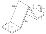
本実施形態の光源ユニット1の変形例2について、図6、図7A,および図7Bを参照して説明する。変形例2の光源ユニット1では、1乃至複数の連結部材6の形状が上述の1乃至複数の連結部材3および変形例1の1乃至複数の連結部材5との形状と異なる。なお、1乃至複数の連結部材6以外の構成は、本実施形態と同じである。   Modification 2 of the light source unit 1 of the present embodiment will be described with reference to FIGS. 6, 7A, and 7B. In the light source unit 1 of Modification 2, the shapes of the one or more connecting members 6 are different from the shapes of the one or more connecting members 3 and the one or more connecting members 5 of Modification 1. The configuration other than the one or more connecting members 6 is the same as that of the present embodiment.

一対の連結部材6のそれぞれは、図6に示すように、長尺な板状に形成される主部61と、板状に形成される一対の爪部62とを有する。一対の爪部62のそれぞれは、主部61の短手方向の中央付近、かつ長手方向の両端のそれぞれに形成される。一対の爪部62のそれぞれは、厚み方向が主部61の長手方向に向いて、主部61の厚み方向の一方向に向かって突出するように形成される。   As shown in FIG. 6, each of the pair of connecting members 6 includes a main portion 61 formed in a long plate shape and a pair of claw portions 62 formed in a plate shape. Each of the pair of claws 62 is formed in the vicinity of the center of the main portion 61 in the short direction and at both ends in the longitudinal direction. Each of the pair of claw portions 62 is formed so that the thickness direction is directed in the longitudinal direction of the main portion 61 and protrudes in one direction of the thickness direction of the main portion 61.

主部61には、長手方向の中央付近に反射部611が設けられる。反射部611は、主部61の長手方向の中心に向かうにつれて、一対の爪部62が突出する方向と同じ方向に突出するように、主部61の長手方向の中心付近が折り曲げられて形成される。つまり、反射部611は、主部61の長手方向の中心が突出するように、主部61の短手方向から見て三角形状に形成される。   The main portion 61 is provided with a reflecting portion 611 near the center in the longitudinal direction. The reflection part 611 is formed by bending the vicinity of the center in the longitudinal direction of the main part 61 so that the reflection part 611 protrudes in the same direction as the direction in which the pair of claw parts 62 protrudes toward the center in the longitudinal direction of the main part 61. The That is, the reflection part 611 is formed in a triangular shape when viewed from the short side direction of the main part 61 so that the center of the main part 61 in the longitudinal direction protrudes.

ところで、変形例2では、図7Aに示すように、隣り合う2つの基板21の距離を距離d31とする。変形例2では、距離d31が上述した隣り合う2つの基板21の距離とする距離d21よりも長くなるように、光源モジュール2がカバー4に収容されている。また、隣り合う2つの基板21のうち、一方の基板21の一端に実装される発光ダイオード221と、他方の基板21の他端に実装される発光ダイオード221との距離を距離d3とする。つまり、変形例2において、複数の光源モジュール2のそれぞれは、距離d1が距離d3よりも短くなるように構成されている。   By the way, in Modification 2, as shown in FIG. 7A, the distance between two adjacent substrates 21 is a distance d31. In the second modification, the light source module 2 is accommodated in the cover 4 so that the distance d31 is longer than the distance d21 that is the distance between the two adjacent substrates 21 described above. Further, the distance between the light emitting diode 221 mounted on one end of one of the two substrates 21 and the light emitting diode 221 mounted on the other end of the other substrate 21 is a distance d3. That is, in Modification 2, each of the plurality of light source modules 2 is configured such that the distance d1 is shorter than the distance d3.

1乃至複数の連結部材6のそれぞれは、図7Aおよび図7Bに示すように、隣り合う2つの基板21の裏面(発光ダイオード22が実装されていない面)に配置される。そして、一対の爪部62のそれぞれは、隣り合う2つの基板21の対応する挿通孔23に、裏面から表面(発光ダイオード22が実装されている面)に向かって挿通される。反射部611は、隣り合う2つの基板21の間から基板21の表面側に向かって突出する。なお、基板21の表面側の反射面612には、表面の形状を加工するなどして、複数の発光ダイオード22からの光を反射するように形成される。このようにして、光源モジュール2の両端付近の光は、反射面612に反射することで、光源モジュール2の両端付近の輝度のばらつきを抑制することが可能である。   As shown in FIGS. 7A and 7B, each of the one or more connecting members 6 is disposed on the back surfaces (surfaces on which the light emitting diodes 22 are not mounted) of two adjacent substrates 21. And each of a pair of nail | claw part 62 is penetrated from the back surface to the surface (surface in which the light emitting diode 22 is mounted) through the corresponding insertion hole 23 of two adjacent board | substrates 21. FIG. The reflection part 611 protrudes from between two adjacent substrates 21 toward the surface side of the substrate 21. The reflective surface 612 on the surface side of the substrate 21 is formed so as to reflect the light from the plurality of light emitting diodes 22 by processing the shape of the surface. In this way, the light near the both ends of the light source module 2 is reflected by the reflecting surface 612, and thus it is possible to suppress variations in luminance near the both ends of the light source module 2.

なお、変形例2の1乃至複数の連結部材6は、距離d3が距離d1よりも長くなるようにカバー4の内部に光源モジュール2が収容されているときに使用されることが好ましい。ただし、1乃至複数の連結部材6は、距離d3が距離d1と同じまたは距離d1よりも短い場合に使用されてもよい。反射部611は、予め三角筒形状または三角柱形状に形成され、主部61の一面の中央付近に取り付けられるように形成されてもよい。また、反射部611は、一対の爪部62と反対の方向に突出するように形成されてもよい。この場合、1乃至複数の連結部材6のそれぞれは、一対の爪部62のそれぞれが基板21の表面から裏面に向かって対応する挿通孔23に挿通されることで、隣り合う2つの基板21を連結してもよい。また、一対の爪部62のそれぞれは、板状に形成される必要ななく、例えば、円筒形状などの形状に形成されてもよい。   In addition, it is preferable that the 1 thru | or several connection member 6 of the modification 2 is used when the light source module 2 is accommodated in the inside of the cover 4 so that the distance d3 may become longer than the distance d1. However, the one or more connecting members 6 may be used when the distance d3 is the same as or shorter than the distance d1. The reflecting portion 611 may be formed in a triangular tube shape or a triangular prism shape in advance, and may be formed to be attached near the center of one surface of the main portion 61. Moreover, the reflection part 611 may be formed so as to protrude in the opposite direction to the pair of claw parts 62. In this case, each of the one or more connecting members 6 is configured such that each of the pair of claw portions 62 is inserted through the corresponding insertion hole 23 from the front surface of the substrate 21 toward the back surface, so that the two adjacent substrates 21 are connected. You may connect. Moreover, each of a pair of nail | claw part 62 does not need to be formed in plate shape, For example, you may form in shapes, such as a cylindrical shape.

変形例2の光源ユニット1において、1乃至複数の連結部材6のそれぞれは、一対の爪部62の間に反射部611を備えることが好ましい。反射部611は、隣り合う2つの基板21間に基板21の一面(表面)側から固体発光素子(発光ダイオード)22,221の照射方向に向かって突出するすように構成されることが好ましい。   In the light source unit 1 of Modification 2, each of the one or more connecting members 6 preferably includes a reflecting portion 611 between the pair of claw portions 62. The reflection part 611 is preferably configured to protrude between the two adjacent substrates 21 from the one surface (front surface) side of the substrate 21 toward the irradiation direction of the solid light emitting elements (light emitting diodes) 22 and 221.

変形例2の光源ユニット1が上述のように構成されると、光源モジュール2の両端付近の輝度のばらつきを抑制することが可能である。つまり、複数の光源モジュール2は、照射面に対してムラなく光を照射することが可能である。   When the light source unit 1 of the modification 2 is configured as described above, it is possible to suppress variations in luminance near both ends of the light source module 2. That is, the plurality of light source modules 2 can irradiate light uniformly with respect to the irradiation surface.

本実施形態の照明器具10について、図8Aおよび図8Bを参照して説明する。なお、以下の説明において、特に断りのない限り、図8Aにおいて上下左右、図8Bにおいて上下前後の各方向を規定する。図8Aにおいて、紙面に垂直な方向を前後方向とし、手前を前、奥を後とする。また、図8Bにおいて、紙面に垂直な方向を左右方向とし、手前を右、奥を左とする。   The lighting fixture 10 of this embodiment is demonstrated with reference to FIG. 8A and FIG. 8B. In the following description, unless otherwise specified, the vertical and horizontal directions in FIG. 8A and the vertical and backward directions in FIG. 8B are defined. In FIG. 8A, the direction perpendicular to the paper surface is the front-rear direction, the front is the front, and the back is the rear. In FIG. 8B, the direction perpendicular to the paper surface is the left-right direction, the front is the right, and the back is the left.

本実施形態の照明器具10は、壁などの造営材100に埋設される照明器具であって、カバー4の長手方向が左右方向となり、複数の発光ダイオード22が前方を向くように造営材100に埋設される。照明器具10は、図8Aおよび図8Bに示すように、器具本体7と、光源ユニット1と、パネル81と、エンドカバー82とを備える。照明器具10は、造営材100の外側(前方)に向かって光が照射するように構成されている(図8B参照)。なお、照明器具10は、電源回路をさらに備えることが好ましい。   The lighting fixture 10 of the present embodiment is a lighting fixture embedded in a construction material 100 such as a wall, and the construction material 100 has a longitudinal direction of the cover 4 in the left-right direction and a plurality of light emitting diodes 22 facing forward. Buried. As illustrated in FIGS. 8A and 8B, the lighting fixture 10 includes a fixture body 7, a light source unit 1, a panel 81, and an end cover 82. The lighting fixture 10 is configured so that light is emitted toward the outside (front) of the building material 100 (see FIG. 8B). In addition, it is preferable that the lighting fixture 10 is further provided with a power supply circuit.

器具本体7は、アルミダイカストなどの金属材料によって形成され、筐体カバー71と、筐体ボディ72とを備える。筐体カバー71は、左右方向に長尺な平板状に形成され、前付近にパネル81を保持する凹部711を備える。筐体ボディ72は、左右方向に長尺な平板状に形成され、前付近にパネル81を保持する凹部721と、光源ユニット1を収容する収容部722とを備える。つまり、図8Bに示すように、光源ユニット1は、筐体ボディ72の収容部722に、照射方向が前方向に向くように、一対の側面421の一方および底壁41が覆われるように収容される。また、光源ユニット1は、筐体カバー71に他方の側面421が覆われる。つまり、光源ユニット1は、筐体ボディ72と筐体カバー71とに上下方向から挟まれて保持される。筐体カバー71と筐体ボディ72とは、底壁41の後方でねじ101とナット102とによって互いに固定される。   The instrument body 7 is formed of a metal material such as aluminum die casting, and includes a casing cover 71 and a casing body 72. The housing cover 71 is formed in a flat plate shape that is long in the left-right direction, and includes a recess 711 that holds the panel 81 in the vicinity of the front. The housing body 72 is formed in a flat plate shape that is long in the left-right direction, and includes a recess 721 that holds the panel 81 in the vicinity of the front, and a storage portion 722 that stores the light source unit 1. That is, as shown in FIG. 8B, the light source unit 1 is accommodated in the accommodating portion 722 of the housing body 72 so that one of the pair of side surfaces 421 and the bottom wall 41 are covered so that the irradiation direction is directed forward. Is done. In the light source unit 1, the other side surface 421 is covered with the housing cover 71. That is, the light source unit 1 is held between the housing body 72 and the housing cover 71 from above and below. The housing cover 71 and the housing body 72 are fixed to each other by a screw 101 and a nut 102 behind the bottom wall 41.

パネル81は、図8Aおよび図8Bに示すように、アクリル樹脂などの透光性を有する合成樹脂材料によって矩形板状に形成される。パネル81は、光源ユニット1の前方に筐体カバー71と筐体ボディ72とによって上下方向から挟まれて、器具本体7に固定される。   As shown in FIGS. 8A and 8B, the panel 81 is formed in a rectangular plate shape by a synthetic resin material having translucency such as acrylic resin. The panel 81 is sandwiched between the housing cover 71 and the housing body 72 in front of the light source unit 1 in the vertical direction and is fixed to the instrument body 7.

エンドカバー82は、図8Aに示すように、アルミダイカストなどの金属材料によって形成され、筐体カバー71および筐体ボディ72の左右両端を覆うようにして、筐体カバー71および筐体ボディ72に取り付けられる。   As shown in FIG. 8A, the end cover 82 is formed of a metal material such as aluminum die casting, and covers the casing cover 71 and the casing body 72 so as to cover the left and right ends of the casing cover 71 and the casing body 72. It is attached.

電源回路は、整流回路、降圧回路などを備える。整流回路は、例えばダイオードブリッジなどで構成され、入力される交流電圧・交流電流を脈流電圧・脈流電流に整流する。降圧回路は、例えばDCDCコンバータなどで構成されており、整流回路から入力される脈流電圧を所定(例えば、5V)の直流電圧に降圧する。つまり、電源回路は、複数の発光ダイオード22が点灯するために必要な直流電圧・直流電流を光源モジュール2に供給する。   The power supply circuit includes a rectifier circuit, a step-down circuit, and the like. The rectifier circuit is configured by a diode bridge, for example, and rectifies an input AC voltage / AC current into a pulsating voltage / current. The step-down circuit is composed of, for example, a DCDC converter, and steps down the pulsating voltage input from the rectifier circuit to a predetermined (for example, 5 V) DC voltage. That is, the power supply circuit supplies the light source module 2 with a DC voltage / DC current necessary for lighting the plurality of light emitting diodes 22.

ところで、造営材100には、照明器具10を収容する上部ブラケット110、下部ブラケット111、および取付金具112が設けられる。下部ブラケット111は、図8Bに示すように、左右方向から見てL字形状に形成される。上部ブラケット110は、前後方向に左右方向から見てV字形状に形成されている。下部ブラケット111は、造営材100に固定されており、上部ブラケット110は、下部ブラケット111にねじ止めされている。上部ブラケット110および下部ブラケット111が互いに固定されることで、上部ブラケット110および下部ブラケット111の間には、照明器具10が収容される収容スペースが設けられる。取付金具112は、左右方向から見てL字形状に形成され、一面が下部ブラケット111にねじ105によって固定されている。取付金具112は、上方向に延出する延出部113を前端に備える。照明器具10は、造営材100の前方から埋設され、筐体ボディ72がねじ103およびナット104によって、取付金具112の延出部113にねじ止めされる。   By the way, the construction material 100 is provided with an upper bracket 110, a lower bracket 111, and a mounting bracket 112 that accommodate the lighting fixture 10. As shown in FIG. 8B, the lower bracket 111 is formed in an L shape when viewed from the left-right direction. The upper bracket 110 is formed in a V shape when viewed from the left-right direction in the front-rear direction. The lower bracket 111 is fixed to the building material 100, and the upper bracket 110 is screwed to the lower bracket 111. Since the upper bracket 110 and the lower bracket 111 are fixed to each other, an accommodation space for accommodating the lighting fixture 10 is provided between the upper bracket 110 and the lower bracket 111. The mounting bracket 112 is formed in an L shape when viewed from the left-right direction, and one surface is fixed to the lower bracket 111 with screws 105. The mounting bracket 112 includes an extending portion 113 that extends upward at the front end. The luminaire 10 is embedded from the front of the building material 100, and the housing body 72 is screwed to the extending portion 113 of the mounting bracket 112 by screws 103 and nuts 104.

本実施形態の照明器具10は、光源ユニット1と、光源ユニット1を保持する器具本体7とを備える。   The lighting fixture 10 of this embodiment includes a light source unit 1 and a fixture body 7 that holds the light source unit 1.

本実施形態の照明器具10は、上述のように構成されるので、照明器具10の軽量化、および作業効率の向上を図ることができる。   Since the lighting fixture 10 of this embodiment is comprised as mentioned above, the weight reduction of the lighting fixture 10 and the improvement of work efficiency can be aimed at.

1 光源ユニット
2 光源モジュール
21 基板
22 発光ダイオード(固体発光素子)
221 発光ダイオード(固体発光素子)
23 挿通孔
3 連結部材
31 主部
32 爪部
4 カバー
41 底壁
411 第1凸部
42 周壁
423 第2凸部
5 連結部材
52 爪部
6 連結部材
611 反射部
62 爪部
d1 距離
d2 距離
DESCRIPTION OF SYMBOLS 1 Light source unit 2 Light source module 21 Board | substrate 22 Light emitting diode (solid light emitting element)
221 Light emitting diode (solid state light emitting device)
DESCRIPTION OF SYMBOLS 23 Insertion hole 3 Connection member 31 Main part 32 Claw part 4 Cover 41 Bottom wall 411 1st convex part 42 Peripheral wall 423 2nd convex part 5 Connection member 52 Claw part 6 Connection member 611 Reflection part 62 Claw part d1 distance d2 distance

Claims (8)

光源モジュールと、1乃至複数の連結部材と、前記1乃至複数の連結部材で連結される前記光源モジュールを収容するカバーとを備え、
前記複数の光源モジュールのそれぞれは、板状に形成される基板と、前記基板の一面に実装される複数の固体発光素子とを有し、
前記基板には、厚み方向に貫通される1乃至複数の挿通孔が前記1乃至複数の連結部材によって連結される方向の両端付近に設けられ、
前記カバーは、長尺の箱状に形成され、かつ前記1乃至複数の連結部材で連結されている前記複数の光源モジュールが長手方向に並んで収容されるように形成され、
前記1乃至複数の連結部材は、板状に形成される主部と、前記主部の一面から突出する一対の爪部とを有し、
前記一対の爪部のそれぞれは、隣り合う2つの前記基板のそれぞれに設けられる前記挿通孔のそれぞれに挿通されている
ことを特徴とする光源ユニット。
A light source module, one or more connecting members, and a cover that houses the light source module connected by the one or more connecting members,
Each of the plurality of light source modules has a substrate formed in a plate shape and a plurality of solid state light emitting devices mounted on one surface of the substrate,
The substrate is provided with one or more insertion holes penetrating in the thickness direction in the vicinity of both ends in the direction connected by the one or more connecting members,
The cover is formed in a long box shape and is formed so that the plurality of light source modules connected by the one or more connecting members are accommodated side by side in the longitudinal direction,
The one or more connecting members have a main part formed in a plate shape and a pair of claw parts protruding from one surface of the main part,
Each of the pair of claw portions is inserted into each of the insertion holes provided in each of the two adjacent substrates. The light source unit.
前記カバーは、内面に第1凸部が形成される底壁と、内面に第2凸部が形成される周壁とを備え、
前記複数の光源モジュールのそれぞれは、前記第1凸部と前記第2凸部との間に保持され、前記基板の他面が前記底壁と向かい合うように、前記カバーの内部に収容されている
ことを特徴とする請求項1に記載の光源ユニット。
The cover includes a bottom wall on which an inner surface is formed with a first protrusion, and a peripheral wall on which an inner surface is formed with a second protrusion.
Each of the plurality of light source modules is held between the first convex portion and the second convex portion, and is accommodated in the cover so that the other surface of the substrate faces the bottom wall. The light source unit according to claim 1.
前記1乃至複数の連結部材の主部は、前記底壁と前記基板との間に収容され、
前記一対の爪部は、前記基板の他面から一面に向かって前記挿通孔に挿通されている
ことを特徴とする請求項2に記載の光源ユニット。
The main part of the one or more connecting members is accommodated between the bottom wall and the substrate,
The light source unit according to claim 2, wherein the pair of claws are inserted into the insertion hole from the other surface of the substrate toward one surface.
前記一対の爪部は、板状に形成され、前記連結部材が前記カバーに収容されている状態において、厚み方向が前記カバーの短手方向と同じ方向になるように形成されている
ことを特徴とする請求項1〜3の何れか一項に記載の光源ユニット。
The pair of claws are formed in a plate shape, and in a state where the connecting member is accommodated in the cover, the thickness direction is formed in the same direction as the short direction of the cover. The light source unit according to claim 1.
前記一対の爪部は、板状に形成され、前記連結部材が前記カバーに収容されている状態において、厚み方向が前記カバーの長手方向と同じ方向になるように形成されている
ことを特徴とする請求項1〜3の何れか一項に記載の光源ユニット。
The pair of claw portions are formed in a plate shape, and in a state where the connecting member is accommodated in the cover, the thickness direction is the same as the longitudinal direction of the cover. The light source unit according to claim 1.
前記複数の基板のそれぞれには、前記複数の固体発光素子が等間隔に配置され、
隣り合う2つの前記基板のうち、一方の前記基板の一端に実装される固体発光素子と、他方の前記基板に実装される前記複数の固体発光素子のうち前記一方の基板に最も近い位置に実装されている固体発光素子との距離が、前記一方の基板に実装される固体発光素子間の距離よりも短くなるように構成されている
ことを特徴とする請求項1〜5の何れか一項に記載の光源ユニット。
On each of the plurality of substrates, the plurality of solid state light emitting elements are arranged at equal intervals,
Mounted at a position closest to one of the solid light-emitting elements mounted on one end of one of the two adjacent substrates and the plurality of solid-state light-emitting elements mounted on the other substrate It is comprised so that the distance with the solid light emitting element currently performed may become shorter than the distance between the solid light emitting elements mounted in said one board | substrate. The light source unit described in 1.
前記1乃至複数の連結部材のそれぞれは、前記一対の爪部の間に反射部を備え、
前記反射部は、隣り合う2つの前記基板間に前記基板の一面側から前記固体発光素子の照射方向に向かって突出するすように構成される
ことを特徴とする請求項1〜5の何れか一項に記載の光源ユニット。
Each of the one or more connecting members includes a reflective portion between the pair of claws,
The said reflection part is comprised so that it may protrude toward the irradiation direction of the said solid light emitting element from the one surface side of the said board | substrate between the two said adjacent board | substrates. The light source unit according to one item.
請求項1〜7の何れか一項に記載の光源ユニットと、前記光源ユニットを保持する器具本体とを備える
ことを特徴とする照明器具。
An illumination fixture comprising: the light source unit according to any one of claims 1 to 7; and a fixture main body that holds the light source unit.
JP2015239542A 2015-12-08 2015-12-08 Light source unit and lighting fixture Pending JP2017107697A (en)

Priority Applications (1)

Application Number Priority Date Filing Date Title
JP2015239542A JP2017107697A (en) 2015-12-08 2015-12-08 Light source unit and lighting fixture

Applications Claiming Priority (1)

Application Number Priority Date Filing Date Title
JP2015239542A JP2017107697A (en) 2015-12-08 2015-12-08 Light source unit and lighting fixture

Publications (1)

Publication Number Publication Date
JP2017107697A true JP2017107697A (en) 2017-06-15

Family

ID=59060810

Family Applications (1)

Application Number Title Priority Date Filing Date
JP2015239542A Pending JP2017107697A (en) 2015-12-08 2015-12-08 Light source unit and lighting fixture

Country Status (1)

Country Link
JP (1) JP2017107697A (en)

Cited By (1)

* Cited by examiner, † Cited by third party
Publication number Priority date Publication date Assignee Title
JP2019067628A (en) * 2017-09-29 2019-04-25 パナソニックIpマネジメント株式会社 Light source device, luminaire, lighting fixture, and lighting system

Cited By (2)

* Cited by examiner, † Cited by third party
Publication number Priority date Publication date Assignee Title
JP2019067628A (en) * 2017-09-29 2019-04-25 パナソニックIpマネジメント株式会社 Light source device, luminaire, lighting fixture, and lighting system
JP6990875B2 (en) 2017-09-29 2022-02-15 パナソニックIpマネジメント株式会社 Lighting equipment, lighting fixtures and lighting systems

Similar Documents

Publication Publication Date Title
JP6248368B2 (en) lighting equipment
JP5572256B2 (en) Light source unit and lighting apparatus
JP6063926B2 (en) lighting equipment
US20170122510A1 (en) Lighting device, fixture body for lighting device, and light-emitting unit
JP2014078424A (en) Lighting fixture
JP6111494B2 (en) lighting equipment
JP6323780B2 (en) lighting equipment
JP6575892B2 (en) Light source module, light source unit and lighting fixture
JP6440058B2 (en) Light source unit and lighting apparatus
JP2017107697A (en) Light source unit and lighting fixture
JP6041210B2 (en) Light source unit and lighting apparatus using the same
JP6399448B2 (en) Light source unit and lighting apparatus
JP6524575B2 (en) lighting equipment
JP2017174569A (en) Light source unit and lighting fixture
JP6820506B2 (en) Light source unit and lighting equipment
JP6799811B2 (en) lighting equipment
JP6528303B2 (en) Light source unit and lighting apparatus
JP5821033B2 (en) Light emitting device
JP7051501B2 (en) Light source unit and lighting equipment
JP7325035B2 (en) lighting equipment
JP6967474B2 (en) Light source unit and lighting equipment
JP6643680B2 (en) lighting equipment
JP7117547B2 (en) Light source unit and lighting equipment
JP6089270B2 (en) lighting equipment
JP2017224391A (en) Light source unit and lighting device

Legal Events

Date Code Title Description
A521 Written amendment

Free format text: JAPANESE INTERMEDIATE CODE: A523

Effective date: 20161011

RD02 Notification of acceptance of power of attorney

Free format text: JAPANESE INTERMEDIATE CODE: A7422

Effective date: 20170127

A621 Written request for application examination

Free format text: JAPANESE INTERMEDIATE CODE: A621

Effective date: 20180926

A977 Report on retrieval

Free format text: JAPANESE INTERMEDIATE CODE: A971007

Effective date: 20190725

A131 Notification of reasons for refusal

Free format text: JAPANESE INTERMEDIATE CODE: A131

Effective date: 20190806

A02 Decision of refusal

Free format text: JAPANESE INTERMEDIATE CODE: A02

Effective date: 20200218