JP2017105475A - Boxing device - Google Patents
Boxing device Download PDFInfo
- Publication number
- JP2017105475A JP2017105475A JP2015238404A JP2015238404A JP2017105475A JP 2017105475 A JP2017105475 A JP 2017105475A JP 2015238404 A JP2015238404 A JP 2015238404A JP 2015238404 A JP2015238404 A JP 2015238404A JP 2017105475 A JP2017105475 A JP 2017105475A
- Authority
- JP
- Japan
- Prior art keywords
- frame member
- boxing
- outer box
- pedestal
- box
- Prior art date
- Legal status (The legal status is an assumption and is not a legal conclusion. Google has not performed a legal analysis and makes no representation as to the accuracy of the status listed.)
- Granted
Links
- 230000007246 mechanism Effects 0.000 claims abstract description 40
- NJPPVKZQTLUDBO-UHFFFAOYSA-N novaluron Chemical compound C1=C(Cl)C(OC(F)(F)C(OC(F)(F)F)F)=CC=C1NC(=O)NC(=O)C1=C(F)C=CC=C1F NJPPVKZQTLUDBO-UHFFFAOYSA-N 0.000 claims abstract description 26
- 238000012856 packing Methods 0.000 claims description 3
- 238000013459 approach Methods 0.000 abstract description 7
- 230000032258 transport Effects 0.000 description 16
- 230000008859 change Effects 0.000 description 11
- 238000001514 detection method Methods 0.000 description 11
- 238000001125 extrusion Methods 0.000 description 8
- 230000006870 function Effects 0.000 description 5
- 230000000452 restraining effect Effects 0.000 description 5
- 238000000034 method Methods 0.000 description 4
- 230000008569 process Effects 0.000 description 4
- 238000010586 diagram Methods 0.000 description 2
- 230000000694 effects Effects 0.000 description 2
- 238000004806 packaging method and process Methods 0.000 description 2
- 238000012546 transfer Methods 0.000 description 2
- 235000010627 Phaseolus vulgaris Nutrition 0.000 description 1
- 244000046052 Phaseolus vulgaris Species 0.000 description 1
- 230000015572 biosynthetic process Effects 0.000 description 1
- 235000009508 confectionery Nutrition 0.000 description 1
- 235000013305 food Nutrition 0.000 description 1
- 238000012986 modification Methods 0.000 description 1
- 230000004048 modification Effects 0.000 description 1
- 230000003287 optical effect Effects 0.000 description 1
- 239000005022 packaging material Substances 0.000 description 1
- 238000005192 partition Methods 0.000 description 1
- 230000002093 peripheral effect Effects 0.000 description 1
- 235000013606 potato chips Nutrition 0.000 description 1
- 238000012545 processing Methods 0.000 description 1
- 230000000630 rising effect Effects 0.000 description 1
- 238000011144 upstream manufacturing Methods 0.000 description 1
Images


Abstract
Description
本発明は、例えば、ポテトチップ、豆、飴等の食品が袋詰め又は箱詰めされた物品を、段ボールケースやダース箱等の外装箱に箱詰めする箱詰め装置に関する。 The present invention relates to a boxing device that packs an article in which a food product such as potato chips, beans, candy or the like is packed or boxed in an outer box such as a cardboard case or a dozen box.
従来、箱詰め装置において、箱詰めされる物品が外装箱にきちんと収納されるように工夫が施されている(例えば、特許文献1参照)。 2. Description of the Related Art Conventionally, in a boxing device, a device has been devised so that articles to be boxed are properly stored in an exterior box (see, for example, Patent Document 1).
特許文献1には、床板(シャッタ)上に整列された物品を、床板を開放して、床板の下方に配置された外装箱に押し込むよう構成された箱詰め装置において、床板の下方に、案内部材が取り付けられて互いに近接又は離間する方向に移動可能に設けられ、物品が通る開口のサイズを規定する第1枠部材及び第2枠部材と、第1枠部材及び第2枠部材の一方端部どうしの間隔を調整する間隔調整機構と、第1枠部材及び第2枠部材の他方端部の動きを一方端部の動きに追従させる追従機構とを備えた案内装置の構成が開示されている。
In
上記特許文献1の構成では、生産される箱詰め品の品種が変更されることにより外装箱のサイズが変更される場合には、作業者が間隔調整機構を操作する等して第1枠部材と第2枠部材との間隔を調整して物品が通る開口のサイズを変更することができるが、人為的な変更ミスが生じる場合がある。
In the configuration of the above-mentioned
本発明は上記のような課題を解決するためになされたもので、箱詰め品の品種が変更された場合に、案内装置の開口のサイズを人為的ミスを無くして変更することができる箱詰め装置を提供することを目的としている。 The present invention has been made in order to solve the above-described problems. When the type of the boxed product is changed, the boxing device that can change the size of the opening of the guide device without human error. It is intended to provide.
上記目的を達成するために、本発明のある形態に係る箱詰め装置は、床板を有し、前記床板を開閉駆動する床開閉装置と、前記床板の上に物品を整列させてなる物品群を整列方向から一対の挟圧板の間に挟圧する挟圧装置と、その箱の上面を形成するための4つのフラップが立った状態の外装箱を支持するとともに昇降可能に構成された台座を有し、前記台座を所定の下降位置から上昇位置へ上昇させることにより前記外装箱を前記床板の下方の箱詰め位置に配置し、前記台座を前記上昇位置から前記下降位置へ下降させることにより前記外装箱を前記箱詰め位置の下方へ退避させる外装箱配置装置と、前記床板が開放された状態において前記挟圧された前記物品群の上面を下方に押して前記物品群を前記挟圧板間から下方に脱出させて、前記箱詰め位置に配置された外装箱に前記物品群を押し込む押込み装置と、前記床板の下方に設けられ、前記押込み装置により押し込まれる前記物品群が通る開口を構成するとともに前記物品群を前記外装箱へ案内する案内装置と、箱詰め品の品種を設定するための操作が行われる操作器と、制御装置とを備え、前記案内装置は、それぞれ前記物品群を前記外装箱へ案内するための案内部材が取り付けられ、互いに近接又は離間する方向に移動可能に設けられ、前記開口のサイズを規定する第1枠部材及び第2枠部材と、前記第1枠部材と前記第2枠部材とを互いに近接又は離間する方向に移動させる移動機構とを有し、前記制御装置は、前記押込み装置によって前記物品群が前記外装箱に押し込まれるときの前記第1枠部材と前記第2枠部材との間隔が前記操作器で設定される品種に応じて予め定められた所定の間隔となるように前記移動機構を制御するよう構成されている。 In order to achieve the above object, a boxing apparatus according to an embodiment of the present invention includes a floor opening and closing device that has a floor board and drives the floor board to open and close, and an article group formed by aligning articles on the floor board. A clamping device for clamping between a pair of clamping plates from a direction, and a base configured to be able to move up and down while supporting an outer box in a state where four flaps for forming the upper surface of the box are standing, The outer box is placed in a boxing position below the floor board by raising the pedestal from a predetermined lowered position to the raised position, and the outer box is packed in the box by lowering the pedestal from the raised position to the lowered position. An outer box disposing device that retreats to the lower side of the position, and presses the upper surface of the clamped article group in a state where the floor board is opened to cause the article group to escape downward from between the clamp plates, A pushing device that pushes the article group into an outer box disposed at a boxing position, and an opening that is provided below the floor board and through which the article group pushed by the pushing device passes, and the article group to the outer box A guide device for guiding, an operation device for performing an operation for setting a product type of the boxed product, and a control device, wherein each of the guide devices includes a guide member for guiding the group of articles to the outer box. A first frame member and a second frame member that are attached and are movable in the direction of approaching or separating from each other, and that define the size of the opening, and the first frame member and the second frame member are close to each other or A moving mechanism for moving in a separating direction, and the control device includes the first frame member and the second frame member when the article group is pushed into the outer box by the pushing device. Are configured to spacing controls the moving mechanism so as to have a predetermined interval set in advance corresponding to varieties set by the operation unit.
この構成によれば、生産する箱詰め品の品種に変更がある場合には、操作器を操作して品種を設定しておくだけで、外装箱が箱詰め位置に配置されて外装箱に物品群が押し込まれるときには、案内装置の物品群が通る開口のサイズを規定する第1枠部材と第2枠部材との間隔を、自動的に品種に応じた所定の間隔にすることができる。よって、箱詰め品の品種が変更された場合に、案内装置の開口のサイズを人為的ミスを無くして変更することができる。 According to this configuration, when there is a change in the type of boxed product to be produced, the outer box is arranged at the boxing position and the group of articles is placed in the outer box simply by operating the operation unit and setting the type. When pushed in, the interval between the first frame member and the second frame member that defines the size of the opening through which the article group of the guide device passes can be automatically set to a predetermined interval corresponding to the product type. Therefore, when the type of the boxed product is changed, the size of the opening of the guide device can be changed without human error.
前記制御装置は、前記第1枠部材と前記第2枠部材との間隔が、前記台座が前記下降位置から前記上昇位置へ上昇するときには前記所定の間隔よりも狭い間隔となり、前記台座が前記上昇位置へ上昇した直後に前記所定の間隔となるように前記移動機構を制御するよう構成されていてもよい。 In the control device, an interval between the first frame member and the second frame member is narrower than the predetermined interval when the pedestal is raised from the lowered position to the raised position, and the pedestal is raised. The moving mechanism may be controlled so as to be at the predetermined interval immediately after rising to the position.
この構成によれば、空の外装箱が箱詰め位置へ上昇するまでは、第1枠部材と第2枠部材との間隔を狭い間隔にしているので、外装箱が案内部材に引っ掛かることなく、箱詰め位置へ上昇させることができる。そして、外装箱が箱詰め位置へ上昇した後、第1枠部材と第2枠部材との間隔を所定の間隔にすることにより、案内部材によって物品群を外装箱へスムーズに案内して、物品を正確に外装箱へ詰め込むことができる。 According to this configuration, the space between the first frame member and the second frame member is kept narrow until the empty outer box rises to the boxing position, so that the outer box does not get caught by the guide member and is packed in the box. Can be raised to position. And after an exterior box raises to a boxing position, by making the space | interval of a 1st frame member and a 2nd frame member into a predetermined space | interval, an article group is smoothly guided to an exterior box by a guide member, Can be accurately packed into the outer box.
前記制御装置は、前記台座が前記上昇位置から前記下降位置へ下降する際には、前記台座が前記上昇位置から下降する直前に、前記第1枠部材と前記第2枠部材との間隔が前記所定の間隔よりも狭い間隔となるように前記移動機構を制御するよう構成されていてもよい。 When the pedestal is lowered from the raised position to the lowered position, the control device is configured such that the interval between the first frame member and the second frame member is immediately before the pedestal is lowered from the raised position. The moving mechanism may be configured to be controlled so as to have an interval narrower than a predetermined interval.
この構成によれば、物品群が収納された外装箱を箱詰め位置から下降させる直前に、第1枠部材と第2枠部材との間隔を狭い間隔にするようにしている。これにより、物品群が収納された外装箱が例えば軽い場合に、外装箱が案内部材に引っ掛かって下降しにくくなるのを防止できる。 According to this configuration, the interval between the first frame member and the second frame member is set to a narrow interval immediately before the outer box in which the article group is stored is lowered from the boxing position. Thereby, when the exterior box in which the article group is stored is light, for example, it is possible to prevent the exterior box from being caught by the guide member and becoming difficult to descend.
前記移動機構は、前記第1枠部材及び前記第2枠部材におけるこれらの移動方向に対して直交する方向の一方端部に設けられ、前記第1枠部材の前記一方端部と前記第2枠部材の前記一方端部とを互いに近接又は離間する方向に移動させる主機構と、前記第1枠部材及び前記第2枠部材におけるこれらの移動方向に対して直交する方向の他方端部に設けられ、前記他方端部のそれぞれの動きを前記一方端部のそれぞれの動きに追従させる追従機構とを有していてもよい。 The moving mechanism is provided at one end of the first frame member and the second frame member in a direction orthogonal to the moving direction, and the one end of the first frame member and the second frame A main mechanism for moving the one end of the member in a direction toward or away from each other, and the other end of the first frame member and the second frame member in a direction perpendicular to the moving direction. And a follow-up mechanism that causes each movement of the other end portion to follow each movement of the one end portion.
この構成によれば、主機構によって第1枠部材及び第2枠部材の一方端部を移動させることにより一方端部どうしの間隔を変更させれば、追従機構によって第1枠部材及び第2枠部材の他方端部が一方端部の動きに追従して他方端部どうしの間隔も変更することができるので、第1枠部材及び第2枠部材の他方端部を移動させるための駆動装置が不要である。 According to this configuration, if the distance between the one end portions is changed by moving the one end portions of the first frame member and the second frame member by the main mechanism, the first frame member and the second frame are changed by the tracking mechanism. Since the other end portion of the member can follow the movement of the one end portion and also change the distance between the other end portions, a driving device for moving the other end portions of the first frame member and the second frame member is provided. It is unnecessary.
本発明は、以上に説明した構成を有し、箱詰め品の品種が変更された場合に、案内装置の開口のサイズを人為的ミスを無くして変更することができる箱詰め装置を提供することができるという効果を奏する。 The present invention can provide a boxing device having the above-described configuration and capable of changing the size of the opening of the guide device without human error when the type of the boxed product is changed. There is an effect.
以下、本発明の好ましい実施の形態を、図面を参照しながら説明する。なお、以下では全ての図面を通じて同一又は相当する要素には同一の参照符号を付して、その重複する説明を省略する。また、本発明は、以下の実施形態に限定されない。 Hereinafter, preferred embodiments of the present invention will be described with reference to the drawings. In the following description, the same or corresponding elements are denoted by the same reference symbols throughout all the drawings, and redundant description thereof is omitted. Further, the present invention is not limited to the following embodiment.
(実施形態)
[全体構成]
図1は、本発明の実施形態の箱詰め装置の一例の概略を示す斜視図である。
(Embodiment)
[overall structure]
FIG. 1 is a perspective view showing an outline of an example of a boxing device according to an embodiment of the present invention.
本実施形態の箱詰め装置100は、例えば、ピロー袋等の包装材で包装された複数の物品Wを整列させた状態で外装箱110に箱詰めする装置である。この箱詰め装置100及び外装箱110において、便宜上、前後左右を図1に示すように決めて説明する。なお、図1に示す上下は真である。
The
この箱詰め装置100は、供給コンベア200から順次供給される物品Wを複数(所定個数)整列させて所定の整列位置Tまで搬送する整列コンベア(物品整列装置)6と、整列コンベア6の整列位置Tから複数の物品Wを整列状態で床板11上の物品載置位置Aへ押し出す押出し装置7と、物品載置位置Aへ押し出された複数の物品Wからなる物品群と当接する止め部材17と、物品載置位置Aへ押し出された物品群を押出方向から押さえることによって止め部材17とともに物品群を位置決めする(姿勢を整える)押さえ装置18と、物品載置位置Aへ押し出された複数の物品Wからなる物品群を押出方向と直交する水平方向から挟圧する挟圧装置8と、物品群が載置されている床(一対の床板11)を開閉する床開閉装置10と、物品群を外装箱110に押し込む押込み装置9と、外装箱110に押し込まれる物品群を外装箱110に案内する案内装置40(図2)と、外装箱110を床開閉装置10の下方に配置する外装箱配置装置20と、箱詰め装置100の動作を制御する制御装置30と、操作表示器50と、これら箱詰め装置100の各構成要素を所定の位置に支持する枠体1と、を有している。
The
[供給コンベアの構成]
供給コンベア200は、例えばベルトコンベアによって構成され、縦ピロー包装機等のような前段の装置(図示省略)から複数の物品Wが順次供給されると、これらの物品Wを搬送して整列コンベア6へ供給する。
[Configuration of supply conveyor]
The
[整列コンベアの構成]
整列コンベア6は、複数の物品Wを立てた状態で1列に整列させるものであり、複数の物品Wを一方向(図1では左から右に向かう方向)に搬送する無端軌道60と、無端軌道の搬送面60aに搬送方向に間隔を隔てて設けられた複数のフィン(仕切板)61とを有している。複数のフィン61によってフィン61間の無端軌道60上に物品Wを収容できる収容部62が複数連なって形成される。
[Configuration of alignment conveyor]
The aligning
無端軌道60は、4本の環状ベルトが一対のスプロケット63によって支持されている。4本の環状ベルトは2本ずつに分かれて第1ベルト群64及び第2ベルト群65を構成している。第1ベルト群64及び第2ベルト群65にはそれぞれ、フィン61が複数装着されている。第1ベルト群64は、一方のスプロケット63によって回転駆動され、第2ベルト群65は、他方のスプロケット63によって回転駆動されるように構成されている。一対のスプロケット63のそれぞれは、別々のモータによって駆動される。これによって、第1ベルト群64及び第2ベルト群65を互いに独立して循環駆動することができ、一方のベルト群が暫時停止を繰り返しながら物品取り込み位置Sにおいて収容部62に物品Wを受け入れる動作と、他方のベルト群が収容部62の物品Wを整列位置Tにおいて停止させた状態を保持する動作とを同時に行うことができる。
The
また、整列コンベア6の上流側には、物品取込検出装置69が設けられている。物品取込検出装置69は、一対の投光器及び受光器を備え、その光路が物品取り込み位置Sを横切るように配設され、物品取り込み位置Sに移送されてきた物品Wの存在を検出することができる。
In addition, an article take-in
上記のように、整列コンベア6は、物品取り込み位置Sにおいて供給コンベア200から移送されてくる物品Wを順次受け取り、これら物品Wの姿勢を寝た姿勢から直立した姿勢に転換すると共に一列に整列し、整列位置Tへ搬送する。
As described above, the
[押出し装置の構成]
押出し装置7は、複数のスリット71が形成された平板状の押出部材70を備えている。そして、押出部材70は、駆動装置(図示せず)の駆動力によってレール部材(図示せず)に案内されて、整列コンベア6の一方の側に沿って位置する退避位置と、整列コンベア6の他方の側の所定の進出位置との間で、水平方向に進出及び退避動作するように構成されている。複数のスリット71は、押出部材70が退避位置と進出位置との間を進出及び退避動作する際に、整列位置Tに位置する複数のフィン61に接触しないよう、押出部材70の下端から中間部にかけて鉛直方向に延びるように形成されている。
[Configuration of extrusion equipment]
The
押出部材70が、退避位置(図示されている位置)から進出動作(x方向へ移動)して進出位置まで進出することにより、整列コンベア6上に整列された複数の物品Wが通路部73上を通って物品載置位置Aへ押し出される。なお、通路部73には、押出部材70によって押し出された複数の物品Wが散乱することを防止するために一対の案内板74が設けられている。
When the push-
したがって、整列位置Tに位置する一連の収容部62に収容された複数の物品Wは、押出部材70によって押し出されて、整列コンベア6の搬送方向に整列した物品群となり、閉じた床板11上に設定された物品載置位置Aに載置される。
Accordingly, the plurality of articles W accommodated in the series of
[止め部材の構成]
止め部材17は、整列コンベア6の延伸方向と同方向に延びる板状体であり、進出位置に位置する押出部材70と対向するように枠体1に固定されて設けられている。したがって、押出部材70によって物品載置位置Aへ押し出された物品Wは、止め部材17と当接し、閉じた床板11上で停止するよう構成されている。
[Structure of stopper member]
The
[押さえ装置の構成]
押さえ装置18は、押さえ部材19と、それを揺動動作させる駆動装置(図示せず)とを備えている。駆動装置としては、例えばサーボモータを用いることができる。押さえ部材19は、それが実線で示された位置である押さえ位置と、この押さえ位置から押さえ部材19を整列コンベア6側に回動させた退避位置(二点鎖線で示された位置)との間を揺動するよう構成されている。
[Configuration of holding device]
The
押さえ部材19を二点鎖線で示す退避位置に位置させることにより、押出部材70の進退動作時における押出部材70との接触を回避することができる。一方、押出部材70の後退後において、押さえ部材19を押さえ位置に位置させることにより、押出部材70により押し出された物品群の上部側面を押さえ、止め部材17とともに、物品載置位置Aに位置する物品群の各物品Wの幅方向の位置を整える。
By positioning the pressing
[挟圧装置の構成]
挟圧装置8は、一対の平板状の挟圧板80を備えている。この一対の挟圧板80は、一対の床板11の上方において、一対の案内板74の延長線上に配設される。即ち、一対の挟圧板80は、押出部材70の移動方向と直交(交差)する水平方向に対向して設けられている。そして、この一対の挟圧板80は、止め部材17の近傍にまで延伸している。そして、床板11の上には、止め部材17、押さえ位置に位置する押さえ部材19及び一対の挟圧板80によって区画された領域が形成される。この領域が物品載置位置Aを構成する。そして、物品群は、押出し装置7によって、物品載置位置A上に一対の挟圧板80が対向する方向に整列した状態で載置される。
[Configuration of the clamping device]
The
そして、各挟圧板80の背面には水平方向に延びる軸体81が設けられている。各軸体81は挟圧板80と共に駆動装置(図示せず)の駆動力により、一対の挟圧板80が互いに近づく方向及び互いに遠ざかる方向に進退動作するように構成されている。一対の挟圧板80が互いに近づく方向に進出することによって、物品載置位置Aに位置する物品群がその整列方向Yから一対の挟圧板80の間に挟圧されるので、物品載置位置Aに位置する物品W同士を密着させることができる。
A
[床開閉装置の構成]
床開閉装置10は、整列コンベア6の側方に配設され、水平方向に延びる一対の床板11を備えている。一対の床板11は、その縁部が枠体1に配設された複数のローラに支持され、互いに対向する端面同士が接触及び離間するようにして進退自在に構成されている。そして、一対の床板11は、駆動装置(図示せず)の駆動力により開閉駆動されるように構成されている。この駆動装置にはサーボモータなどの公知のアクチュエータを用いることができる。一対の床板11が後退駆動されると、物品載置位置Aの直下に開口が形成される(床板11が開放される)。
[Configuration of floor opening and closing device]
The floor opening /
[押込み装置の構成]
押込み装置9は、鉛直方向に延びる軸体90と、軸体90の下端がその上面に接合された押込み部材91とを有している。軸体90は、枠体1に昇降自在に支持されている。そして、軸体90は、押込み部材91と共に駆動装置(図示せず)の駆動力により鉛直方向に昇降するように構成されている。この駆動装置にはサーボモータなどの公知のアクチュエータを用いることができる。この押込み装置9は、押込み部材91を下降させることにより、物品載置位置Aの物品群の上面を下方に押して同物品群を一対の挟圧板80の間から下方に脱出させて、開放した一対の床板11の間の開口及び後述の案内装置40の開口W1(図2)を介して、箱詰め位置Pに位置している外装箱110に押し込むことができる。
[Configuration of pushing device]
The pushing
また、本例では、押込み部材91の下面には、物品群の上面を吸着するための吸着口が設けられており、この吸着口には、真空ポンプ及びサクションブロア等の吸込み口が連通されている。すなわち、押込み部材91は、物品群の上面を吸着する吸着具として機能し、物品群の上面を吸着して保持した状態で所定位置まで下降することにより、物品群を外装箱110に押し込むことができる。
In this example, a suction port for sucking the upper surface of the article group is provided on the lower surface of the pushing
[外装箱配置装置の構成]
外装箱配置装置20は、外装箱110を水平搬送する外装箱搬送コンベア22と、外装箱搬送コンベア22上に停止している外装箱110を持ち上げる外装箱昇降装置21とを有している。
[Configuration of exterior box placement device]
The exterior
外装箱搬送コンベア22は、いわゆる駆動ローラコンベアであり、互いに平行に離間して配設された多数の駆動ローラ22aを備えている。各駆動ローラ22aは、駆動装置(図示せず)の駆動力によって駆動され、これにより、外装箱110がy方向へ搬送される。
The outer
外装箱昇降装置21は、外装箱110が載置される台座24を備えている。台座24は、同一水平面上において互いに平行に離間して配置された複数の棒材24aと、各棒材24aの一方又は両方の端部を連結する連結材24bとを備えている。棒材24aは、箱停止位置Uの駆動ローラ22a間の隙間に埋没可能に構成されている。台座24は、公知の昇降装置(図示せず)に支持されている。そして、台座24は、昇降装置の駆動装置の駆動力により昇降動作できるように構成されている。すなわち、台座24は、棒材24aが駆動ローラ22a間の隙間に埋没した状態となる所定の下降位置と、所定の上昇位置との間で、昇降動作する。台座24が所定の上昇位置にあるときに、台座24上の外装箱110が箱詰め位置Pとなるように構成されている。
The outer box lifting / lowering
制止装置23は、台座24に取り付けられ、外装箱搬送コンベア22の搬送方向(y方向)と直交するようにして水平方向に延びる棒体23aを進退させる装置であり、例えばエアシリンダで構成することができる。制止装置23は、棒体23aを外装箱搬送コンベア22の搬送路へ進出させることにより、外装箱110を物品載置位置Aの下方の箱停止位置Uに停止させることができ、棒体23aを外装箱搬送コンベア22の搬送路から退避させることにより、外装箱110を箱停止位置Uから下流側へ搬送させることができる。
The restraining
また、箱検出装置25が連結材24b上に設けられている。よって、箱検出装置25は、台座24と共に昇降する。箱検出装置25は、光電センサで構成され、箱停止位置U(又は箱詰め位置P)に位置する外装箱110の存在を検出することができる。
A
このように外装箱配置装置20は、箱詰め装置100に搬入された外装箱110を外装箱搬送コンベア22によって搬送し、制止装置23の棒体23aによって箱停止位置Uに位置させることができる。そして、外装箱配置装置20は、台座24を、駆動ローラ22a間の隙間に棒材24aが埋没されている状態の下降位置から、所定の上昇位置へ上昇させることによって、外装箱110の下面(底面)が棒材24aによって支持された状態で外装箱110を持ち上げて箱詰め位置Pに位置させることができる。そして、外装箱110に物品が収納された後、外装箱配置装置20は、台座24を下降位置まで下降させることによって、この外装箱110を箱停止位置Uに再び戻し、更に、制止装置23の棒体23aを退避させることにより、外装箱110を外装箱搬送コンベア22によって箱詰め装置100から搬出することができる。
Thus, the exterior
[案内装置の構成]
図2(A)は、案内装置40を上から視た平面図であり、図2(B)は、案内装置40の正面図であり、図2(C)は、図2(A)におけるA−A断面図である。
[Configuration of guide device]
2A is a plan view of the
案内装置40は、図2(B)に示すように、床板11の直下に設けられている。また、図2(A)及び図2(B)において、二点鎖線で示された外装箱110は、箱詰め位置Pに位置している状態を示している。
The
外装箱110は、例えば、4つのフラップ(蓋板)F1〜F4が閉じられたときに立方体または直方体形状をなすダンボール箱である。外装箱110は、その上面(上蓋)を形成するための4つのフラップF1〜F4が立った状態(上方へ延びた状態)、すなわち外装箱110の上面が開口された状態で、箱詰め装置100に搬入され、同状態で箱詰め装置100から搬出される。
The
案内装置40は、押込み装置9により押し込まれる物品群が通る開口W1を構成するとともに、この開口W1を通る物品群を外装箱110に案内するためのものであり、互いに平行に配置される第1,第2枠部材41,42と、第1,第2枠部材41,42に取り付けられた第1,第2案内部材43,44と、第1枠部材41と第2枠部材42とを互いに近接または離間する方向に移動させる移動機構4Aとを備えている。
The
第1枠部材41及び第2枠部材42は、開口W1の内周部における前部及び後部を構成するとともに、開口W1のサイズを規定する部材であり、棒状に形成されている。そして、第1,第2枠部材41,42のそれぞれが、床板11の開閉方向(=物品群の整列方向Y)と同じ方向に延びて、互いに近接又は離間する方向に移動可能に設けられている。第1枠部材41及び第2枠部材42の互いに向き合う内側面に、第1案内部材43及び第2案内部材44が取り付けられている。
The
第1,第2案内部材43,44の上部は、図2(C)に示すように、物品を案内できるように上方へ向かうにつれて外側に向けて傾斜している。また、第1,第2案内部材43,44のそれぞれは、外装箱110の互いに対向するフラップF1,F3が内側へ倒れないように下方へ延びた垂下部43a、44aを有している。
As shown in FIG. 2 (C), the upper portions of the first and
移動機構4Aは、主機構4Bと、追従機構4Cとで構成される。まず、主機構4Bについて説明する。
The moving
主機構4Bは、ガイドレール45と、ガイドレール45にその長手方向に沿って移動自在に取り付けられた2つの移動ブロック46a,46bと、直動機構47と、第1,第2主動アーム48,49とを有している。
The
ガイドレール45及び2つの移動ブロック46a,46bは、いわゆるリニアガイドで構成することができる。移動ブロック46a,46bのそれぞれには、第1,第2枠部材41,42の一方の端部が固定されている。また、ガイドレール45は、ガイドレール取付部材101に固定されており、ガイドレール取付部材101の両端は枠体1に支持される。
The
そして、直動機構47が、ガイドレール取付部材101から左方へ延びる取付部材102上に固定されている。取付部材102は、一端がガイドレール取付部材101の略中央下部に固定され、他端が枠体1に支持されている。
The
図3は、直動機構47の一例を示す斜視図である。図3に示すように、直動機構47は、例えば、スライドテーブル47aと、断面略U字形状のガイドレール47bと、ボールねじ47cと、ボールねじ47cに連結されエンコーダを有するモータ47d等を有して構成されている。スライドテーブル47aは、ガイドレール47bの内側に配置され、ボールねじ47cが螺合されるナット部と、ガイドレール47bにその長手方向に沿って移動自在に取り付けられた移動ブロックとの機能を有している。モータ47dには、サーボモータを用いることができる。この直動機構47では、モータ47dが正逆回転することによりボールねじ47cが正逆回転し、スライドテーブル47aが左右方向に移動する。このような直動機構47は、市販のものを用いることができ、図3に示すものに限られない。
FIG. 3 is a perspective view showing an example of the
そして、図2に示すように、第1主動アーム48によって一方の移動ブロック46aとスライドテーブル47aとが連結され、第2主動アーム49によって他方の移動ブロック46bとスライドテーブル47aとが連結されている。ここで、第1主動アーム48は、その一端が一方の移動ブロック46a上に固定された軸a2に回動自在に取り付けられ、他端がスライドテーブル47a上に固定された軸a1に回動自在に取り付けられている。同様に、第2主動アーム49は、その一端が他方の移動ブロック46b上に固定された軸a3に回動自在に取り付けられ、他端がスライドテーブル47a上に固定された軸a1に回動自在に取り付けられている。
As shown in FIG. 2, one moving
次に、追従機構4Cは、主機構4Bのガイドレール45と平行に配置されるガイドレール51と、ガイドレール51にその長手方向に沿って移動自在に取り付けられた2つの移動ブロック52a,52bと、ガイドレール53及び移動ブロック54と、第1,第2従動アーム55,56とを有している。
Next, the follow-up
ガイドレール51及び2つの移動ブロック52a,52bは、いわゆるリニアガイドで構成することができる。移動ブロック52a,52bのそれぞれの上面には、第1,第2枠部材41,42の他方の端部が固定されている。また、ガイドレール51は、ガイドレール取付部材103に固定されており、ガイドレール取付部材103の両端は枠体1に支持される。
The
そして、ガイドレール取付部材103から左方へ延びる取付部材104上に、ガイドレール53が固定されている。そしてガイドレール53にその長手方向に沿って移動自在に移動ブロック54が取り付けられている。ガイドレール53及び移動ブロック54は、いわゆるリニアガイドで構成することができる。取付部材104は、一端がガイドレール取付部材103の下面の略中央部に固定され、他端が枠体1に支持されている。
A
そして、第1従動アーム55によって一方の移動ブロック52aと移動ブロック54とが連結され、第2従動アーム56によって他方の移動ブロック52bと移動ブロック54とが連結されている。ここで、第1従動アーム55は、その一端が一方の移動ブロック52a上に固定された軸a5に回動自在に取り付けられ、他端が移動ブロック54上に固定された軸a4に回動自在に取り付けられている。同様に、第2従動アーム56は、その一端が他方の移動ブロック52b上に固定された軸a6に回動自在に取り付けられ、他端が移動ブロック54上に固定された軸a4に回動自在に取り付けられている。
One moving
上記構成により、直動機構47のモータ47dが正逆回転することによりボールねじ47cが正逆回転し、スライドテーブル47aが左右方向に移動する。例えば、スライドテーブル47aが左方へ移動すると、移動ブロック46a,46bが互いに接近する方向へ移動し、それに伴い、第1,第2枠部材41,42が互いに近づく方向へ移動し、その他端の移動ブロックが52a,52bが互いに接近して移動ブロック54が右方へ移動する。一方、スライドテーブル47aが右方へ移動すると、移動ブロック46a,46bが互いに離れる方向へ移動し、それに伴い、第1,第2枠部材41,42が互いに離れる方向へ移動し、その他端の移動ブロックが52a,52bが互いに離れて移動ブロック54が左方へ移動する。このようにして、第1枠部材41と第2枠部材42との間隔(第1案内部材43と第2案内部材44との間隔)を調整ないし変更することができる。
With the above configuration, when the
[制御系統の構成]
図4は、箱詰め装置100の制御系統の概略構成の一例を示すブロック図である。
[Configuration of control system]
FIG. 4 is a block diagram illustrating an example of a schematic configuration of a control system of the
箱詰め装置100が備える制御装置30は、例えば、CPU等の演算器を有する制御部31と、ROM及びRAM等のメモリを有する記憶部32とを備えている。物品取込検出装置69から出力される物品検出信号及び箱検出装置25から出力される箱検出信号は、制御部31に入力される。記憶部32には所定の制御プログラムが記憶されていて、制御部31がこれらの制御プログラムを読み出して実行することにより、制御装置30は、整列コンベア6、押出し装置7、挟圧装置8、押込み装置9、床開閉装置10、押さえ装置18、外装箱配置装置20、案内装置40及び操作表示器50の各装置の動作を制御する。すなわち、制御装置30によって、箱詰め装置100全体の動作が制御される。なお、制御装置30は、集中制御する単独の制御装置で構成されていてもよいし、互いに協働して分散制御する複数の制御装置で構成されていてもよい。
The
操作表示器50は、例えばタッチパネルディスプレイ等を用いて構成され、箱詰め装置の運転開始・停止等の操作およびその運転パラメータ等の設定を行うための操作器と、箱詰め装置の設定情報等をスクリーン(ディスプレイ画面)に表示する表示器とを備えている。
The
また、制御装置30は、操作表示器50からの信号を入力するとともに、操作表示器50へ表示するデータ等の信号を出力する。
In addition, the
作業者は、操作表示器50を操作して、生産する箱詰め品の品種を設定することができる。ここで設定された品種は制御装置30内の記憶部32に記憶される。また、記憶部32には、予め、複数の各品種に用いられる外装箱のサイズに応じた、開口W1の前後方向のサイズを規定する第1枠部材41と第2枠部材42との間隔を設定するためのモータ47dの回転角度の情報(以下、「間隔設定情報」という)が記憶されている。
The operator can set the type of boxed product to be produced by operating the
まず、作業者は、箱詰め装置100の運転開始前に、操作表示器50を操作して、生産する箱詰め品の品種を設定する。この設定は、例えば、操作表示器50の操作によって、操作表示器50の画面に、生産可能な複数の品種名を表示させて、その中から1つを選択操作することによって行うことができる。
First, before starting the operation of the
制御装置30は、操作表示器50の操作によって設定された品種に応じた間隔設定情報に基づいて、案内装置40のモータ47dを制御し、第1枠部材41と第2枠部材42との間隔を所定の間隔(L1)に設定することができる。さらに、本例では、制御装置30は、第1枠部材41と第2枠部材42との間隔を、品種に応じた所定の間隔L1よりも狭い間隔L2(L2=L1−m、mは所定値)となるようにモータ47dを制御することができる。
The
[箱詰め装置の動作]
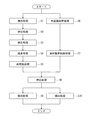
図5は、箱詰め装置100の動作の一例を示すフローチャートである。この動作は、制御装置30の処理によって実現される。
[Operation of boxing device]
FIG. 5 is a flowchart illustrating an example of the operation of the
前述のように、運転開始前に、作業者は、操作表示器50を操作して、生産する箱詰め品の品種を設定する。これにより、制御装置30は、案内装置40(モータ47d)を制御して、第1枠部材41と第2枠部材42との間隔を、設定された品種に応じた所定の間隔L1よりも狭い間隔L2にさせる。
As described above, before the operation is started, the operator operates the
そして、運転を開始させると、ステップS1において、制御装置30は、整列コンベア6を制御して、供給コンベア200より順次供給される物品Wを、所定個数、整列位置Tにおいて整列させる。
When the operation is started, in step S1, the
次に、ステップS2において、制御装置30は、押出し装置7を制御して、押出部材70を退避位置から進出位置に移動させることにより、整列位置Tにおいて整列した物品Wを床板11上へ押し出させる。そして、制御装置30は、押出部材70を進出位置から退避位置に戻す。これにより物品群が物品載置位置Aに整列状態で載置される。
Next, in step S <b> 2, the
次に、ステップS3において、制御装置30は、押さえ装置18を制御して、押さえ部材19を下方に揺動させて押さえ位置にし、押し出された物品群の上部側面を押さえさせる。これによって、各物品Wは、押さえ部材19及び止め部材17によって整列方向Yと直交する水平方向の両端部が揃った状態となる。続いて、制御装置30は、挟圧装置8を制御して、一対の挟圧板80が互いに近づく方向に挟圧板80をそれぞれ進出させる。これによって、物品群がその整列方向Yから挟圧されて物品W同士を密着させることができる。
Next, in step S3, the
次に、ステップS4において、制御装置30は、押込み装置9を制御して、吸着機能を有する押込み部材91を、挟圧された物品群の上面に接触するように降下させ、物品群の上面を吸着させる。これによって物品群が押込み部材91に保持される。
Next, in step S4, the
次に、ステップS5において、制御装置30は、床開閉装置10を制御して、一対の床板11を後退駆動させる。これによって、物品載置位置Aに位置する物品群の直下に開口が形成される。
Next, in step S5, the
一方、制御装置30は、ステップS1〜S5の処理と並行して、外装箱配置処理(ステップS6)と案内装置制御処理(ステップS7)とを行う。
On the other hand, the
ステップS6では、制御装置30は、予め制止装置23の棒体23aを進出位置に位置させた状態にしており、外装箱搬送コンベア22で搬入されてきた外装箱110を箱停止位置Uに停止させる。そして、制御装置30は、箱検出装置25から箱検出信号を入力すると、外装箱搬送コンベア22の搬送動作を停止させて、台座24を上昇させ、箱停止位置Uの外装箱110を箱詰め位置Pに位置させる。
In step S <b> 6, the
次に、ステップS7では、制御装置30は、案内装置40を制御して、第1枠部材41と第2枠部材42との間隔を、狭い間隔L2から設定品種に応じた所定の間隔L1に広げる。
Next, in step S7, the
次に、ステップS8において、制御装置30は、押込み装置9を制御して、物品群を吸着している押込み部材91を降下させることによって、外装箱110に物品群を押し込む。この際、物品群は一対の挟圧板80を滑り抜けて、一対の床板11の開口及び案内装置40の開口W1を通過して、外装箱110内部に案内される。
Next, in step S <b> 8, the
次に、ステップS9において、制御装置30は、押込み装置9、案内装置40、床開閉装置10などを元の状態に復帰させる。例えば、押込み装置9は、押込み部材91の吸着機能を停止させた後、押込み部材91を物品群の形成位置の上方にまで上昇させる。この押込み部材91の上昇後、案内装置40を制御して、第1枠部材41と第2枠部材42との間隔を、所定の間隔L1から狭い間隔L2にするとともに、床板11を閉鎖する。また、押さえ部材19を退避位置へ戻し、挟圧板80を後退させて元の位置へ戻す。
Next, in step S9, the
そして、制御装置30は、ステップS9と並行してステップS10の処理を行う。ステップS10では、台座24を下降させて物品群を収容した外装箱110を箱停止位置Uに位置させた後、制止装置23の棒体23aを搬送路から退避させ、外装箱搬送コンベア22の搬送動作を再開させて外装箱110を箱詰め装置100から搬出する。
And the
なお、本例では、ステップS9において、案内装置40の第1枠部材41と第2枠部材42との間隔を、狭い間隔L2にした後(直後)に、ステップS10における台座24を下降させるようにしている。
In this example, after the interval between the
そして、上記と同様の箱詰め動作が新たに繰り返される。 Then, the same boxing operation as described above is newly repeated.
この箱詰め装置100では、生産する箱詰め品の品種に変更(があって、図1における外装箱110の前後方向の寸法に変更)がある場合には、操作表示器50を操作して品種を設定しておくだけで、外装箱110が箱詰め位置Pに配置されて外装箱110に物品群が押し込まれるときには、第1枠部材41と第2枠部材42との間隔を、自動的に品種に応じた所定の間隔L1にすることができる。よって、箱詰め品の品種が変更された場合に、案内装置40の開口W1のサイズを人為的ミスを無くして変更することができる。また、案内装置40の段取り替えの作業が不要となり、品種変更に伴う段取り替えの作業時間の短縮化が可能になる。
In this
また、本例では、空の外装箱110が箱詰め位置Pへ上昇するまでは、第1枠部材41と第2枠部材42との間隔を狭い間隔L2にしているので、外装箱110が案内部材43,44の下端部の垂下部43a,44aに引っ掛かることなく、箱詰め位置Pへ上昇させることができる。そして、外装箱110が箱詰め位置Pへ上昇した後、第1枠部材41と第2枠部材42との間隔を所定の間隔L1にすることにより、案内部材43,44の垂下部43a,44aが外装箱110のフラップF1,F3の内側に接し、フラップF1,F3が正常に開いた状態を維持できるので、押し込まれる物品群を外装箱110へスムーズに案内して、物品を正確に外装箱110へ詰め込むことができる。
In this example, until the empty
さらに本例のように、物品群が収納された外装箱110を、箱詰め位置Pから下降させる前に、第1枠部材41と第2枠部材42との間隔を狭い間隔L2にするようにしている。これは、物品群が収納された外装箱110が例えば軽い場合に、外装箱110が案内部材43,44の下方へ延びた垂下部43a、44aに引っ掛かって下降しにくくなるのを防止できる。
Further, as in this example, before the
なお、上記の実施形態では、外装箱110に収納される物品群として、押込み装置9による1回の押込み動作によって押し込まれた複数の物品としたが、n回(nは2以上の所定の整数)の押込み動作によって押し込まれる複数の物品(すなわちn段に積まれた物品)となるように構成してもよい。また、この場合に、n回目以前の押込み動作(例えば1回目の押込み動作)が行われた直後に、案内装置40の第1枠部材41と第2枠部材42との間隔が、所定の間隔L1から、狭い間隔L3(L3は、L1より小さく、L2でもよい)と広い間隔L4(L4は、L1でもよいし、L1より若干大きくてもよい)との間で繰り返し変更されてから所定の間隔L1へ戻すように、案内装置40を動作させるようにしてよい。すなわち、案内部材43,44の垂下部43a,44aでフラップF1,F3を所定回数たたくようにしてもよい。これにより、外装箱110が揺らされて、押し込まれた物品が整然と収まる効果がある。
In the above embodiment, the group of articles stored in the
なお、案内部材43,44は図2に示すものに限られない。例えば、垂下部43a,44aの形状等は、適宜変更することができる。
The
上記説明から、当業者にとっては、本発明の多くの改良や他の実施形態が明らかである。従って、上記説明は、例示としてのみ解釈されるべきであり、本発明を実行する最良の態様を当業者に教示する目的で提供されたものである。本発明の精神を逸脱することなく、その構造及び/又は機能の詳細を実質的に変更できる。 From the foregoing description, many modifications and other embodiments of the present invention are obvious to one skilled in the art. Accordingly, the foregoing description should be construed as illustrative only and is provided for the purpose of teaching those skilled in the art the best mode of carrying out the invention. The details of the structure and / or function may be substantially changed without departing from the spirit of the invention.
本発明は、箱詰め品の品種が変更された場合に、案内装置の開口のサイズを人為的ミスを無くして変更することができる箱詰め装置等として有用である。 INDUSTRIAL APPLICABILITY The present invention is useful as a boxing device or the like that can change the size of the opening of the guide device without human error when the type of the boxed product is changed.
6 整列コンベア
7 押出し装置
8 挟圧装置
9 押込み装置
10 床開閉装置
11 床板
20 外装箱配置装置
24 台座
30 制御装置
40 案内装置
41 第1枠部材
42 第2枠部材
43,44 案内部材
4A 移動機構
4B 主機構
4C 追従機構
50 操作表示器
80 挟圧板
110 外装箱
P 箱詰め位置
F1〜F4 フラップ
W1 開口
6
Claims (4)
前記床板の上に物品を整列させてなる物品群を整列方向から一対の挟圧板の間に挟圧する挟圧装置と、
その箱の上面を形成するための4つのフラップが立った状態の外装箱を支持するとともに昇降可能に構成された台座を有し、前記台座を所定の下降位置から上昇位置へ上昇させることにより前記外装箱を前記床板の下方の箱詰め位置に配置し、前記台座を前記上昇位置から前記下降位置へ下降させることにより前記外装箱を前記箱詰め位置の下方へ退避させる外装箱配置装置と、
前記床板が開放された状態において前記挟圧された前記物品群の上面を下方に押して前記物品群を前記挟圧板間から下方に脱出させて、前記箱詰め位置に配置された外装箱に前記物品群を押し込む押込み装置と、
前記床板の下方に設けられ、前記押込み装置により押し込まれる前記物品群が通る開口を構成するとともに前記物品群を前記外装箱へ案内する案内装置と、
箱詰め品の品種を設定するための操作が行われる操作器と、
制御装置と
を備え、
前記案内装置は、
それぞれ前記物品群を前記外装箱へ案内するための案内部材が取り付けられ、互いに近接又は離間する方向に移動可能に設けられ、前記開口のサイズを規定する第1枠部材及び第2枠部材と、
前記第1枠部材と前記第2枠部材とを互いに近接又は離間する方向に移動させる移動機構とを有し、
前記制御装置は、
前記押込み装置によって前記物品群が前記外装箱に押し込まれるときの前記第1枠部材と前記第2枠部材との間隔が前記操作器で設定される品種に応じて予め定められた所定の間隔となるように前記移動機構を制御するよう構成された、
箱詰め装置。 A floor opening and closing device having a floor plate and driving the floor plate to open and close;
A clamping device that clamps a group of articles formed by aligning articles on the floor board between a pair of clamping plates from the alignment direction;
The pedestal has a pedestal configured to support the exterior box in a state where four flaps for forming the upper surface of the box are standing and can be raised and lowered, and by raising the pedestal from a predetermined lowered position to a raised position, An outer box is disposed at a boxing position below the floorboard, and an outer box placing device for retracting the outer box below the boxing position by lowering the pedestal from the raised position to the lowered position;
In the state where the floor board is opened, the upper surface of the pressed article group is pushed downward to cause the article group to escape downward from between the pressing plates, and the article group is placed on the outer box disposed at the packing position. A pushing device for pushing in,
A guide device which is provided below the floor plate and forms an opening through which the group of articles pushed by the pushing device passes, and guides the group of articles to the exterior box;
An operation device that performs operations for setting the type of boxed product,
A control device,
The guide device includes:
A first frame member and a second frame member, each of which is provided with a guide member for guiding the group of articles to the outer box, is provided so as to be movable in a direction close to or away from each other, and defines a size of the opening;
A moving mechanism for moving the first frame member and the second frame member in directions close to or away from each other;
The controller is
The interval between the first frame member and the second frame member when the article group is pushed into the exterior box by the pushing device is a predetermined interval that is predetermined according to the type set by the operating device. Configured to control the moving mechanism to be
Boxing equipment.
前記第1枠部材と前記第2枠部材との間隔が、前記台座が前記下降位置から前記上昇位置へ上昇するときには前記所定の間隔よりも狭い間隔となり、前記台座が前記上昇位置へ上昇した直後に前記所定の間隔となるように前記移動機構を制御するよう構成された、
請求項1に記載の箱詰め装置。 The controller is
The interval between the first frame member and the second frame member is smaller than the predetermined interval when the pedestal is raised from the lowered position to the raised position, and immediately after the pedestal is raised to the raised position. Configured to control the moving mechanism to be at the predetermined interval.
The boxing device according to claim 1.
前記台座が前記上昇位置から前記下降位置へ下降する際には、前記台座が前記上昇位置から下降する直前に、前記第1枠部材と前記第2枠部材との間隔が前記所定の間隔よりも狭い間隔となるように前記移動機構を制御するよう構成された、
請求項1または2に記載の箱詰め装置。 The controller is
When the pedestal is lowered from the raised position to the lowered position, immediately before the pedestal is lowered from the raised position, an interval between the first frame member and the second frame member is larger than the predetermined interval. Configured to control the moving mechanism so as to be a narrow interval;
The boxing apparatus according to claim 1 or 2.
前記第1枠部材及び前記第2枠部材におけるこれらの移動方向に対して直交する方向の一方端部に設けられ、前記第1枠部材の前記一方端部と前記第2枠部材の前記一方端部とを互いに近接又は離間する方向に移動させる主機構と、
前記第1枠部材及び前記第2枠部材におけるこれらの移動方向に対して直交する方向の他方端部に設けられ、前記他方端部のそれぞれの動きを前記一方端部のそれぞれの動きに追従させる追従機構とを有する、
請求項1〜3のいずれかに記載の箱詰め装置。 The moving mechanism is
The one end of the first frame member and the one end of the second frame member are provided at one end of the first frame member and the second frame member in a direction orthogonal to the moving direction thereof. A main mechanism for moving the parts in directions toward or away from each other;
It is provided at the other end of the first frame member and the second frame member in the direction orthogonal to the moving direction, and each movement of the other end follows the movement of the one end. Having a follow-up mechanism,
The boxing apparatus in any one of Claims 1-3.
Priority Applications (1)
| Application Number | Priority Date | Filing Date | Title |
|---|---|---|---|
| JP2015238404A JP6685586B2 (en) | 2015-12-07 | 2015-12-07 | Boxing equipment |
Applications Claiming Priority (1)
| Application Number | Priority Date | Filing Date | Title |
|---|---|---|---|
| JP2015238404A JP6685586B2 (en) | 2015-12-07 | 2015-12-07 | Boxing equipment |
Publications (2)
| Publication Number | Publication Date |
|---|---|
| JP2017105475A true JP2017105475A (en) | 2017-06-15 |
| JP6685586B2 JP6685586B2 (en) | 2020-04-22 |
Family
ID=59058624
Family Applications (1)
| Application Number | Title | Priority Date | Filing Date |
|---|---|---|---|
| JP2015238404A Active JP6685586B2 (en) | 2015-12-07 | 2015-12-07 | Boxing equipment |
Country Status (1)
| Country | Link |
|---|---|
| JP (1) | JP6685586B2 (en) |
Cited By (3)
| Publication number | Priority date | Publication date | Assignee | Title |
|---|---|---|---|---|
| CN111003258A (en) * | 2019-11-14 | 2020-04-14 | 华南智能机器人创新研究院 | Pay-off module and equipment |
| CN111003281A (en) * | 2019-11-14 | 2020-04-14 | 华南智能机器人创新研究院 | Bagged particle packing machine |
| JP2020063076A (en) * | 2018-10-18 | 2020-04-23 | 大和製衡株式会社 | Box packing device |
Citations (11)
| Publication number | Priority date | Publication date | Assignee | Title |
|---|---|---|---|---|
| JPH0699905A (en) * | 1992-09-21 | 1994-04-12 | Fuji Mach Co Ltd | Driving system controller of case packer |
| JPH06122403A (en) * | 1992-10-12 | 1994-05-06 | Fuji Mach Co Ltd | Automatic size changing device for corrugated fiberboard box packing machine |
| JPH08119217A (en) * | 1994-10-28 | 1996-05-14 | Nippon Seiki Co Ltd | Packaging apparatus |
| JPH08183517A (en) * | 1994-12-29 | 1996-07-16 | Dainippon Printing Co Ltd | Casing device |
| JP2000136011A (en) * | 1998-10-30 | 2000-05-16 | O M Ltd | Packaging device |
| JP2002019707A (en) * | 2000-07-12 | 2002-01-23 | Yamato Scale Co Ltd | Casing apparatus |
| JP2005335734A (en) * | 2004-05-25 | 2005-12-08 | Yamato Scale Co Ltd | Inserting apparatus, inserting method and automatic boxing apparatus |
| JP2005335733A (en) * | 2004-05-25 | 2005-12-08 | Yamato Scale Co Ltd | Inserting apparatus, inserting method and automatic boxing apparatus |
| JP2012166788A (en) * | 2011-02-10 | 2012-09-06 | Yamato Scale Co Ltd | Boxing apparatus |
| JP2012224368A (en) * | 2011-04-20 | 2012-11-15 | Yamato Scale Co Ltd | Article pushing device and boxing apparatus using the same |
| WO2013121550A1 (en) * | 2012-02-16 | 2013-08-22 | 日本たばこ産業株式会社 | Machine for packing article into box |
-
2015
- 2015-12-07 JP JP2015238404A patent/JP6685586B2/en active Active
Patent Citations (11)
| Publication number | Priority date | Publication date | Assignee | Title |
|---|---|---|---|---|
| JPH0699905A (en) * | 1992-09-21 | 1994-04-12 | Fuji Mach Co Ltd | Driving system controller of case packer |
| JPH06122403A (en) * | 1992-10-12 | 1994-05-06 | Fuji Mach Co Ltd | Automatic size changing device for corrugated fiberboard box packing machine |
| JPH08119217A (en) * | 1994-10-28 | 1996-05-14 | Nippon Seiki Co Ltd | Packaging apparatus |
| JPH08183517A (en) * | 1994-12-29 | 1996-07-16 | Dainippon Printing Co Ltd | Casing device |
| JP2000136011A (en) * | 1998-10-30 | 2000-05-16 | O M Ltd | Packaging device |
| JP2002019707A (en) * | 2000-07-12 | 2002-01-23 | Yamato Scale Co Ltd | Casing apparatus |
| JP2005335734A (en) * | 2004-05-25 | 2005-12-08 | Yamato Scale Co Ltd | Inserting apparatus, inserting method and automatic boxing apparatus |
| JP2005335733A (en) * | 2004-05-25 | 2005-12-08 | Yamato Scale Co Ltd | Inserting apparatus, inserting method and automatic boxing apparatus |
| JP2012166788A (en) * | 2011-02-10 | 2012-09-06 | Yamato Scale Co Ltd | Boxing apparatus |
| JP2012224368A (en) * | 2011-04-20 | 2012-11-15 | Yamato Scale Co Ltd | Article pushing device and boxing apparatus using the same |
| WO2013121550A1 (en) * | 2012-02-16 | 2013-08-22 | 日本たばこ産業株式会社 | Machine for packing article into box |
Cited By (6)
| Publication number | Priority date | Publication date | Assignee | Title |
|---|---|---|---|---|
| JP2020063076A (en) * | 2018-10-18 | 2020-04-23 | 大和製衡株式会社 | Box packing device |
| JP7118552B2 (en) | 2018-10-18 | 2022-08-16 | 大和製衡株式会社 | cartoning equipment |
| CN111003258A (en) * | 2019-11-14 | 2020-04-14 | 华南智能机器人创新研究院 | Pay-off module and equipment |
| CN111003281A (en) * | 2019-11-14 | 2020-04-14 | 华南智能机器人创新研究院 | Bagged particle packing machine |
| CN111003281B (en) * | 2019-11-14 | 2021-11-02 | 华南智能机器人创新研究院 | Bagged particle packing machine |
| CN111003258B (en) * | 2019-11-14 | 2021-11-02 | 华南智能机器人创新研究院 | Pay-off module and equipment |
Also Published As
| Publication number | Publication date |
|---|---|
| JP6685586B2 (en) | 2020-04-22 |
Similar Documents
| Publication | Publication Date | Title |
|---|---|---|
| JP5514524B2 (en) | Package conveyor | |
| JP2016210616A5 (en) | ||
| JP6685586B2 (en) | Boxing equipment | |
| JP2018090308A (en) | Equipment for packing in box | |
| JP5822480B2 (en) | Boxing equipment | |
| KR101125154B1 (en) | Apparatus for lining up cartons | |
| JP3208782U (en) | Boxing equipment | |
| JP2016088721A (en) | Article transfer device | |
| JP5774324B2 (en) | Boxing equipment | |
| JP6602137B2 (en) | Boxing equipment | |
| JP6921766B2 (en) | Insert device | |
| JP7118552B2 (en) | cartoning equipment | |
| JP7114416B2 (en) | cartoning equipment | |
| JP2021116100A (en) | Box packing device | |
| KR102294935B1 (en) | Multi-Row Apparatus for Folding Box | |
| JP7191464B2 (en) | cartoning equipment | |
| JP5046591B2 (en) | Boxing equipment | |
| JPH09267803A (en) | Method and equipment for collecting and boxing article | |
| WO2007084261A2 (en) | Transversely-adjustable carton hopper | |
| JP2021098529A (en) | Boxing device | |
| JP7114419B2 (en) | cartoning system | |
| JP2012171626A (en) | Box shaping apparatus for boxing equipment | |
| JP7305282B2 (en) | Pushing device and cartoning device with the same | |
| JP2013159359A (en) | Boxing apparatus and boxing method using the same | |
| JP5266939B2 (en) | Article conveying device |
Legal Events
| Date | Code | Title | Description |
|---|---|---|---|
| A621 | Written request for application examination |
Free format text: JAPANESE INTERMEDIATE CODE: A621 Effective date: 20181004 |
|
| A977 | Report on retrieval |
Free format text: JAPANESE INTERMEDIATE CODE: A971007 Effective date: 20190826 |
|
| A131 | Notification of reasons for refusal |
Free format text: JAPANESE INTERMEDIATE CODE: A131 Effective date: 20190917 |
|
| A521 | Request for written amendment filed |
Free format text: JAPANESE INTERMEDIATE CODE: A523 Effective date: 20191007 |
|
| TRDD | Decision of grant or rejection written | ||
| A01 | Written decision to grant a patent or to grant a registration (utility model) |
Free format text: JAPANESE INTERMEDIATE CODE: A01 Effective date: 20200331 |
|
| A61 | First payment of annual fees (during grant procedure) |
Free format text: JAPANESE INTERMEDIATE CODE: A61 Effective date: 20200331 |
|
| R150 | Certificate of patent or registration of utility model |
Ref document number: 6685586 Country of ref document: JP Free format text: JAPANESE INTERMEDIATE CODE: R150 |
|
| R250 | Receipt of annual fees |
Free format text: JAPANESE INTERMEDIATE CODE: R250 |
|
| R250 | Receipt of annual fees |
Free format text: JAPANESE INTERMEDIATE CODE: R250 |