JP2017105235A - Vehicle air conditioner - Google Patents
Vehicle air conditioner Download PDFInfo
- Publication number
- JP2017105235A JP2017105235A JP2015238494A JP2015238494A JP2017105235A JP 2017105235 A JP2017105235 A JP 2017105235A JP 2015238494 A JP2015238494 A JP 2015238494A JP 2015238494 A JP2015238494 A JP 2015238494A JP 2017105235 A JP2017105235 A JP 2017105235A
- Authority
- JP
- Japan
- Prior art keywords
- air
- passage
- cold air
- outlet
- hot
- Prior art date
- Legal status (The legal status is an assumption and is not a legal conclusion. Google has not performed a legal analysis and makes no representation as to the accuracy of the status listed.)
- Granted
Links
Images


Classifications
-
- B—PERFORMING OPERATIONS; TRANSPORTING
- B60—VEHICLES IN GENERAL
- B60H—ARRANGEMENTS OF HEATING, COOLING, VENTILATING OR OTHER AIR-TREATING DEVICES SPECIALLY ADAPTED FOR PASSENGER OR GOODS SPACES OF VEHICLES
- B60H1/00—Heating, cooling or ventilating [HVAC] devices
- B60H1/00007—Combined heating, ventilating, or cooling devices
- B60H1/00021—Air flow details of HVAC devices
- B60H1/00064—Air flow details of HVAC devices for sending air streams of different temperatures into the passenger compartment
-
- B—PERFORMING OPERATIONS; TRANSPORTING
- B60—VEHICLES IN GENERAL
- B60H—ARRANGEMENTS OF HEATING, COOLING, VENTILATING OR OTHER AIR-TREATING DEVICES SPECIALLY ADAPTED FOR PASSENGER OR GOODS SPACES OF VEHICLES
- B60H1/00—Heating, cooling or ventilating [HVAC] devices
-
- B—PERFORMING OPERATIONS; TRANSPORTING
- B60—VEHICLES IN GENERAL
- B60H—ARRANGEMENTS OF HEATING, COOLING, VENTILATING OR OTHER AIR-TREATING DEVICES SPECIALLY ADAPTED FOR PASSENGER OR GOODS SPACES OF VEHICLES
- B60H1/00—Heating, cooling or ventilating [HVAC] devices
- B60H1/00007—Combined heating, ventilating, or cooling devices
- B60H1/00021—Air flow details of HVAC devices
- B60H2001/00078—Assembling, manufacturing or layout details
- B60H2001/00092—Assembling, manufacturing or layout details of air deflecting or air directing means inside the device
Abstract
Description
本発明は、例えば自動車等に搭載される車両用空調装置に関し、特に温風と冷風とを個別に生成して混合させることによって所望温度の空調風を得る構造の技術分野に属する。 The present invention relates to a vehicle air conditioner mounted on, for example, an automobile, and particularly relates to a technical field of a structure in which air conditioned air having a desired temperature is obtained by separately generating and mixing hot air and cold air.
一般に、自動車等に搭載される車両用空調装置は、ヒートポンプのエバポレータからなる冷却用熱交換器と、エンジン冷却水が循環するヒータコアからなる加熱用熱交換器と、これら熱交換器を収容するケーシングとを備えている。そして、ケーシングに導入された空調用空気を冷却用熱交換器及び加熱用熱交換器によってそれぞれ冷風及び温風にした後、冷風及び温風を混合させて空調風を得て、その後、デフロスト吹出口、ベント吹出口及びヒート吹出口のうち、選択された吹出口に空調風を供給することによって車室の空調を行うことができるようになっている(例えば、特許文献1〜4参照。)。
Generally, a vehicle air conditioner mounted on an automobile or the like includes a cooling heat exchanger composed of an evaporator of a heat pump, a heating heat exchanger composed of a heater core through which engine cooling water circulates, and a casing that houses these heat exchangers. And. Then, after the air conditioning air introduced into the casing is cooled and warmed by the cooling heat exchanger and the heating heat exchanger, respectively, the cold air and the warm air are mixed to obtain the conditioned air, and then the defrost blowing is performed. The vehicle compartment can be air-conditioned by supplying conditioned air to a selected air outlet among the outlet, the vent air outlet, and the heat air outlet (see, for example,
特許文献1では、ケーシングの内部に、温風通路と冷風通路との合流部位に配置されるバッフルプレートが収容されている。バッフルプレートには、温風通路からの温風をデフロスト吹出口方向に導く複数の温風ガイド溝が設けられており、これら温風ガイド溝の間では、冷風通路からの冷風と温風通路からの温風とを混合させるようにしている。
In
特許文献2のケーシングにも温風通路と冷風通路との合流部位にバッフルプレートが収容されている。特許文献2のバッフルプレートは、温風が流れる温風通路と、冷風と温風とが合流して混合風となって流れる混合風通路とを有しており、温風通路と混合風通路とが幅方向で交互に配置されている。
Also in the casing of
特許文献3では、ケーシングの内部に、温風通路と冷風通路との合流部位に温風ガイド部材が収容されている。温風ガイド部材は、温風の一部をデフロスト吹出口にガイドする温風ガイド通路を有しており、温風ガイド通路の外側で冷風と温風とを混合させるように構成されている。
In
特許文献4では、ケーシングの内部に、温風通路と冷風通路との合流部位に整流プレートが収容されている。整流プレートは、温風の一部をデフロスト吹出口にガイドする温風案内筒を有しており、温風案内筒の外側で冷風と温風とを混合させるように構成されている。
In
ところで、近年、車両用空調装置の更なる小型化が要求されており、熱交換器等をはじめてとしてケーシングについても小型化が検討されている。ケーシングを小型化するということは、ケーシングの内部空間が小さくなることを意味しており、例えば冷風と温風とを混合させるためのエアミックス空間も小容積化する必要がある。エアミックス空間が小さくなると冷風と温風が混ざりにくくなり、温度コントロール性能が悪化する。 By the way, in recent years, further downsizing of a vehicle air conditioner has been demanded, and downsizing of casings as well as heat exchangers has been studied. Downsizing the casing means that the internal space of the casing is reduced. For example, an air mix space for mixing cold air and hot air needs to be reduced in volume. When the air mix space becomes smaller, it becomes difficult for cold air and hot air to mix, and the temperature control performance deteriorates.
そこで、特許文献1〜4のようにケーシングの内部にバッフルプレート等を収容して温度コントロール性能の改善を図ることが考えられる。ところが、エアミックス空間が更に小さくなった場合には、特許文献1〜4のバッフルプレート等では温度コントロール性能を満足することは困難であると考えられる。
Therefore, it is conceivable to improve the temperature control performance by accommodating a baffle plate or the like inside the casing as in
その理由は以下のとおりである。一般に冷風通路の冷風は加熱用熱交換器を通過していないことによって温風通路の温風に比べて勢いが強くなっており、冷風量が温風量よりも多くなり易い。特許文献1〜4のバッフルプレート等は、この冷風と温風の勢いの差、即ち風量の差に鑑みて構成されていて、エアミックス空間で冷風と温風とを単純に混合させると冷風が勝って狙い通りの温度コントロールが難しくなるので、温風をデフロスト吹出口方向に優先的に導くようにしており、他の部分では冷風と温風とを混合させるようにしている。このようにしたとしても、冷風の勢いが上述したように強いため、デフロスト吹出口が開状態にある吹出モードではデフロスト吹出口へ向けて流れる冷風量が多くなり、その結果、デフロスト吹出口へ向けて流れる温風量が少なくなり、狙いとする温度よりも低温の空調風が吹き出すことになる。このため、デフロスト吹出口から吹き出す空調風によってフロントガラスの曇りを晴らす性能を満足できなくなる恐れがある。
The reason is as follows. Generally, the cold air in the cold air passage is stronger than the hot air in the hot air passage because it does not pass through the heat exchanger for heating, and the amount of cold air tends to be larger than the amount of hot air. The baffle plates and the like of
本発明は、かかる点に鑑みてなされたものであり、その目的とするところは、小型化されたケーシング内に冷風及び温風の流れを制御するバッフルを設ける場合に、温度コントロール性能を向上させて快適性を向上させることにある。 The present invention has been made in view of such points, and the object of the present invention is to improve the temperature control performance when a baffle for controlling the flow of cold air and hot air is provided in a downsized casing. It is to improve comfort.
上記目的を達成するために、本発明では、温風及び冷風の合流部位に配設したバッフルによって温風をデフロスト吹出口方向に案内する一方、冷風をベント吹出口方向にも案内するようにした。 In order to achieve the above object, in the present invention, the hot air is guided in the direction of the defrost outlet by the baffle disposed at the confluence portion of the hot air and the cold air, while the cold air is also guided in the direction of the vent outlet. .
第1の発明は、
空調用空気を冷却する冷却用熱交換器と、
空調用空気を加熱する加熱用熱交換器と、
上記冷却用熱交換器が配置される冷風通路と、該冷風通路の下流側に連通し、上記加熱用熱交換器が配置される温風通路と、上記冷風通路の下流側から分岐して上記温風通路をバイパスして延びるバイパス通路と、上記温風通路及び上記バイパス通路の下流側が連通するエアミックス空間と、該エアミックス空間に連通するデフロスト吹出口、ベント吹出口及びヒート吹出口とが設けられたケーシングと、
上記ケーシングの内部に配設され、上記温風通路及び上記バイパス通路の下流側からそれぞれ上記エアミックス空間に流入する温風量及び冷風量を調整するエアミックスダンパとを備えた車両用空調装置において、
上記ケーシングの内部には、温風及び冷風の合流部位にバッフルが配設され、
上記バッフルには、上記温風通路からの温風を上記デフロスト吹出口方向に導く温風ガイド部と、上記バイパス通路からの冷風を上記ベント吹出口方向及び上記ヒート吹出口方向の少なくとも一方に導く冷風ガイド部とが設けられていることを特徴とする。
The first invention is
A cooling heat exchanger for cooling the air-conditioning air;
A heat exchanger for heating air for air conditioning,
The cold air passage in which the cooling heat exchanger is disposed, the hot air passage in communication with the downstream side of the cold air passage, the hot air passage in which the heating heat exchanger is disposed, and the downstream from the cold air passage. A bypass passage extending by bypassing the hot air passage, an air mix space communicating with the hot air passage and the downstream side of the bypass passage, a defrost outlet, a vent outlet and a heat outlet communicating with the air mix space. A provided casing;
An air conditioner for a vehicle provided with an air mix damper that is arranged inside the casing and adjusts the amount of hot air and the amount of cold air flowing into the air mix space from the downstream side of the hot air passage and the bypass passage, respectively.
Inside the casing, a baffle is disposed at a confluence site of hot air and cold air,
The baffle guides the hot air from the hot air passage toward the defrost outlet, and guides the cold air from the bypass passage to at least one of the vent outlet direction and the heat outlet direction. A cold air guide part is provided.
この構成によれば、冷風通路を流れる空調用空気が冷却用熱交換器によって冷却されて冷風となる。この冷風が温風通路を流れると加熱用熱交換器によって加熱されて温風になる一方、バイパス通路を流れると冷風のままとなる。そして、エアミックスダンパの動作によってエアミックス空間に流入する温風量及び冷風量が調整されてエアミックス空間で所望温度の空調風が生成された後、吹出モードに応じてデフロスト吹出口やベント吹出口から吹き出して車室の各部に供給される。 According to this configuration, the air-conditioning air flowing through the cold air passage is cooled by the cooling heat exchanger and becomes cold air. When this cold air flows through the hot air passage, it is heated by the heat exchanger for heating to become hot air, while when it flows through the bypass passage, it remains cold air. Then, after the amount of warm air and the amount of cold air flowing into the air mix space are adjusted by the operation of the air mix damper and the conditioned air at a desired temperature is generated in the air mix space, the defrost outlet and vent outlet according to the blowing mode And then supplied to each part of the passenger compartment.
温風通路からの温風がバッフルの温風ガイド部によってデフロスト吹出口方向に導かれるので、デフロスト吹出口への温風量が確保される。さらに、このときバイパス通路からの冷風がバッフルの冷風ガイド部によってベント吹出口方向及びヒート吹出口方向の少なくとも一方に導かれるので、加熱用熱交換器を通過していない勢いの強い冷風がデフロスト吹出口方向に向けて流れ難くなる。これにより、デフロスト吹出口から吹き出す空調風の温度低下が回避される。 Since the warm air from the warm air passage is guided toward the defrost outlet by the warm air guide part of the baffle, the amount of warm air to the defrost outlet is ensured. Further, at this time, the cold air from the bypass passage is guided to at least one of the vent air outlet direction and the heat air outlet direction by the cold air guide portion of the baffle, so that the strong cold air not passing through the heating heat exchanger is defrosted. It becomes difficult to flow toward the exit. Thereby, the temperature fall of the air-conditioning wind which blows off from a defrost blower outlet is avoided.
また、冷風がバッフルの冷風ガイド部によってベント吹出口方向及びヒート吹出口方向の少なくとも一方に導かれるので、主に夏季に選択されるベントモード時にベント吹出口から吹き出す空調風の温度が低温になるとともに、空調風の風量が十分に確保される。 In addition, since the cold air is guided to at least one of the vent air outlet direction and the heat air outlet direction by the cold air guide portion of the baffle, the temperature of the air-conditioning air blown from the vent air outlet at the vent mode selected mainly in summer is low. At the same time, a sufficient amount of conditioned air is ensured.
尚、バッフルの冷風ガイド部が冷風をベント吹出口方向のみに導くようにしてもよいし、ヒート吹出口方向のみに導くようにしてもよいし、ベント吹出口方向及びヒート吹出口方向に導くようにしてもよい。 In addition, the cool air guide part of the baffle may guide the cool air only in the vent outlet direction, may be guided only in the heat outlet direction, or may be guided in the vent outlet direction and the heat outlet direction. It may be.
第2の発明は、第1の発明において、
上記ベント吹出口は上記デフロスト吹出口の下方に設けられ、
上記冷風ガイド部は、上記バッフルの下側に設けられていることを特徴とする。
According to a second invention, in the first invention,
The vent outlet is provided below the defrost outlet,
The cold air guide part is provided below the baffle.
この構成によれば、ベント吹出口をデフロスト吹出口の下方に設けるレイアウトとする場合に、冷風ガイド部がバッフルの下側に位置することになるので、冷風ガイド部により冷風がベント吹出口に効率よく導かれる。 According to this configuration, when the layout is provided with the vent air outlet below the defrost air outlet, the cold air guide portion is located below the baffle. Well guided.
第3の発明は、第1または2の発明において、
上記バッフルには、上記温風通路からの温風と、上記バイパス通路からの冷風とを混合させるための温冷風混合通路が設けられ、
上記冷風ガイド部は、筒状に形成されるとともに、上記バッフルにおける上記温冷風混合通路の流れ方向上流側に位置付けられることを特徴とする。
According to a third invention, in the first or second invention,
The baffle is provided with a hot / cold air mixing passage for mixing hot air from the hot air passage and cold air from the bypass passage,
The cold air guide portion is formed in a cylindrical shape and is positioned on the upstream side in the flow direction of the hot and cold air mixing passage in the baffle.
この構成によれば、温冷風混合通路の流れ方向上流側の流路が冷風ガイド部によって絞られることになる。これにより、温冷風混合通路に流入する温風の流速が高まり、温風と冷風との混合性が良好になる。また、温風が温風ガイド部に流入し易くなるので、温風ガイド部による効果がより顕著なものになる。 According to this configuration, the flow path upstream in the flow direction of the hot and cold air mixing passage is narrowed by the cold air guide portion. Thereby, the flow velocity of the hot air flowing into the hot / cold air mixing passage is increased, and the mixing property of the hot air and the cold air is improved. Moreover, since warm air easily flows into the warm air guide part, the effect of the warm air guide part becomes more remarkable.
第4の発明は、第1から3のいずれか1つの発明において、
上記デフロスト吹出口は、上記ケーシングの上壁部に設けられ、
上記バッフルには、上記バイパス通路からの冷風を下方へ導くように延びる冷風側板部が設けられていることを特徴とする。
According to a fourth invention, in any one of the first to third inventions,
The defrost outlet is provided on the upper wall of the casing,
The baffle is provided with a cold air side plate portion extending so as to guide the cold air from the bypass passage downward.
この構成によれば、バイパス通路からの冷風がバッフルの冷風側板部によってデフロスト吹出口から離れる方向に導かれるので、冷風がデフロスト吹出口に向けて流れ難くなり、デフロスト吹出口から吹き出す空調風の温度低下が回避される。 According to this configuration, since the cold air from the bypass passage is guided in the direction away from the defrost outlet by the cold air side plate portion of the baffle, the temperature of the conditioned air blown from the defrost outlet becomes difficult because the cold air does not easily flow toward the defrost outlet. Reduction is avoided.
第5の発明は、第1から4のいずれか1つの発明において、
上記ヒート吹出口は、上記デフロスト吹出口及び上記ベント吹出口の下方に設けられ、
上記バッフルの下部には、上記温風通路からの温風が上記ヒート吹出口へ向けて流れるのを阻止する温風側板部が下方へ延びるように設けられていることを特徴とする。
According to a fifth invention, in any one of the first to fourth inventions,
The heat outlet is provided below the defrost outlet and the vent outlet,
At the lower part of the baffle, a hot air side plate portion for preventing the hot air from the hot air passage from flowing toward the heat outlet is provided to extend downward.
この構成によれば、温風通路からの温風がバッフルの下部からヒート吹出口に向けて漏れにくくなるので、バッフルによる温風のガイド効果が十分に得られるようになる。 According to this configuration, since the warm air from the warm air passage is less likely to leak from the lower part of the baffle toward the heat outlet, the effect of guiding the warm air by the baffle can be sufficiently obtained.
第6の発明は、第1から5のいずれか1つの発明において、
上記ベント吹出口は、上記ケーシングの車幅方向両側に設けられ、
上記冷風ガイド部は、上記バッフルの車幅方向両側に設けられ、上記車幅方向両側のベント吹出口方向に冷風を導くことを特徴とする。
A sixth invention is the invention according to any one of the first to fifth aspects,
The vent outlet is provided on both sides of the casing in the vehicle width direction,
The said cold wind guide part is provided in the vehicle width direction both sides of the said baffle, and guides cold wind to the vent blower outlet direction of the said vehicle width direction both sides, It is characterized by the above-mentioned.
この構成によれば、風量分配に不利な車幅方向両側に設けられているベント吹出口に冷風が導かれるので、車幅方向両側のベント吹出口から十分な量の冷風を供給することが可能になる。 According to this configuration, since the cool air is led to the vent outlets provided on both sides in the vehicle width direction, which is disadvantageous for air volume distribution, it is possible to supply a sufficient amount of cold air from the vent outlets on both sides in the vehicle width direction. become.
第7の発明は、第1から6のいずれか1つの発明において、
上記温風ガイド部と上記冷風ガイド部とは、互いに異なる方向に延びていることを特徴とする。
A seventh invention is the invention according to any one of the first to sixth inventions,
The hot air guide portion and the cold air guide portion extend in different directions.
この構成によれば、温風ガイド部による温風の流れ方向と、冷風ガイド部による冷風の流れ方向とが異なる場合に、各々を適切な方向に導くことが可能になる。 According to this configuration, when the flow direction of the warm air by the warm air guide portion is different from the flow direction of the cold air by the cold air guide portion, each can be guided in an appropriate direction.
第1の発明によれば、温風及び冷風の合流部位に配設したバッフルに、温風通路からの温風をデフロスト吹出口方向に導く温風ガイド部と、バイパス通路からの冷風をベント吹出口方向及びヒート吹出口方向の少なくとも一方に導く冷風ガイド部とを設けたので、デフロスト吹出口から吹き出す空調風の温度及びベント吹出口から吹き出す空調風の温度を共に適温にすることができる。これにより、高い温度コントロール性能を得ることができ、快適性を向上させることができる。 According to the first aspect of the present invention, the hot air guide section for guiding the hot air from the hot air passage toward the defrost outlet is vented to the baffle disposed at the confluence of the hot air and the cold air, and the cold air from the bypass passage is vented. Since the cold air guide part led to at least one of the outlet direction and the heat outlet direction is provided, both the temperature of the conditioned air blown from the defrost outlet and the temperature of the conditioned air blown from the vent outlet can be set to appropriate temperatures. Thereby, high temperature control performance can be obtained and comfort can be improved.
第2の発明によれば、ベント吹出口をデフロスト吹出口の下方に設けるレイアウトとする場合に冷風ガイド部により冷風をベント吹出口に効率よく導くことができる。 According to the second aspect of the invention, when the vent air outlet is arranged below the defrost air outlet, the cold air can be efficiently guided to the vent air outlet by the cold air guide portion.
第3の発明によれば、バッフルに温冷風混合通路を設け、冷風ガイド部を筒状に形成して温冷風混合通路の流れ方向上流側に配置したので、温冷風混合通路に流入する温風の流速を高めて冷風との混合性を良好にすることができるとともに、温風ガイド部による効果をより顕著なものにすることができる。 According to the third aspect of the invention, the hot and cold air mixing passage is provided in the baffle, and the cold air guide portion is formed in a cylindrical shape and arranged on the upstream side in the flow direction of the hot and cold air mixing passage. The flow rate of the air can be increased to improve the mixing with the cold air, and the effect of the hot air guide portion can be made more remarkable.
第4の発明によれば、デフロスト吹出口をケーシングの上壁部に設け、バッフルに、バイパス通路からの冷風を下方へ導くように延びる冷風側板部を設けたので、冷風がデフロスト吹出口に向けて流れ難くなり、デフロスト吹出口から吹き出す空調風の温度低下を回避することができる。 According to the fourth aspect of the invention, the defrost outlet is provided in the upper wall portion of the casing, and the baffle is provided with the cold air side plate extending so as to guide the cold air from the bypass passage downward, so that the cold air is directed to the defrost outlet. Therefore, it is difficult to flow and the temperature drop of the conditioned air blown out from the defrost outlet can be avoided.
第5の発明によれば、ヒート吹出口をデフロスト吹出口及びベント吹出口の下方に設け、バッフルの下部に、温風通路からの温風がヒート吹出口へ向けて流れるのを阻止する温風側板部を下方へ延びるように設けたので、温風がバッフルの下部からヒート吹出口へ漏れてしまうのを防止することができ、バッフルによる温風のガイド効果を十分に得ることができる。 According to the fifth aspect of the present invention, the hot air outlet is provided below the defrost outlet and the vent outlet, and the hot air that prevents the warm air from the hot air passage from flowing toward the heat outlet at the lower part of the baffle. Since the side plate portion is provided so as to extend downward, it is possible to prevent the warm air from leaking from the lower part of the baffle to the heat outlet, and the effect of guiding the warm air by the baffle can be sufficiently obtained.
第6の発明によれば、車幅方向両側のベント吹出口方向に冷風を導くことができるので、該ベント吹出口から十分な量の冷風を供給できる。 According to the sixth aspect, since the cool air can be guided toward the vent outlet on both sides in the vehicle width direction, a sufficient amount of cool air can be supplied from the vent outlet.
第7の発明によれば、温風の流れ方向と冷風の流れ方向とが異なる場合に、温風ガイド部及び冷風ガイド部によって温風及び冷風を確実に導くことができる。 According to the seventh aspect, when the flow direction of the hot air is different from the flow direction of the cold air, the hot air and the cold air can be reliably guided by the hot air guide portion and the cold air guide portion.
以下、本発明の実施形態を図面に基づいて詳細に説明する。尚、以下の好ましい実施形態の説明は、本質的に例示に過ぎず、本発明、その適用物或いはその用途を制限することを意図するものではない。 Hereinafter, embodiments of the present invention will be described in detail with reference to the drawings. It should be noted that the following description of the preferred embodiment is merely illustrative in nature, and is not intended to limit the present invention, its application, or its use.
(実施形態1)
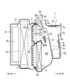
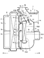
図1〜図3は、本発明の実施形態1に係る車両用空調装置1を示すものである。この車両用空調装置1は、図示しないが、例えば自動車の車室前端部に配設されているインルメントパネルの内部に収容されており、空調用空気を温度調節した後に、車室の各部に供給することができるように構成されている。車両用空調装置1は、車両左右方向の略中央部に配置されている。
(Embodiment 1)
1 to 3 show a
尚、この実施形態の説明では、説明の便宜を図るために、車両前側を単に「前」といい、車両後側を単に「後」といい、車両左側を単に「左」といい、車両右側を単に「右」というものとする。 In the description of this embodiment, for convenience of explanation, the front side of the vehicle is simply referred to as “front”, the rear side of the vehicle is simply referred to as “rear”, the left side of the vehicle is simply referred to as “left”, and the right side of the vehicle is referred to. Is simply called “right”.
車両用空調装置1は、送風ユニット(図示せず)を備えている。送風ユニットは、車室内の空気(内気)と、車室外の空気(外気)とを選択して送風することができるように構成された周知のものであるため詳細な説明は省略するが、内外気切替ダンパ、送風ファン、ファン駆動モーター等を有している。そして、内外気切替ダンパを作動させることによって、内気のみを空調用空気として送風する内気循環モードと、外気のみを空調用空気として送風する外気導入モードとに切り替えられるようになっている。
The
車両用空調装置1は、空調用空気を冷却する冷却用熱交換器2と、空調用空気を加熱する加熱用熱交換器3と、冷却用熱交換器2及び加熱用熱交換器3を収容するケーシング4と、エアミックスダンパ5と、デフロストダンパ6と、ベントダンパ7と、ヒートダンパ8と、バッフル10とを備えている。冷却用熱交換器2は、ヒートポンプの冷媒蒸発器(エバポレータ)で構成されている。冷却用熱交換器2には図示しないクーラ配管が接続されており、図示しない膨張弁を通った冷媒が導入される。導入された冷媒は、冷却用熱交換器2が有する複数のチューブ(図示せず)を通り、このときに、外部を通過する空調用空気と冷媒とフィン(図示せず)を介して熱交換し、これにより空調用空気が冷却される。
The
加熱用熱交換器3は、この車両に搭載されているエンジンの冷却水が循環するヒータコアで構成されている。加熱用熱交換器3には図示しないヒータ配管が接続されている。加熱用熱交換器3に導入されたエンジンの冷却水は、加熱用熱交換器3が有する複数のチューブ(図示せず)を通り、このときに、外部を通過する空調用空気とエンジンの冷却水とがフィン(図示せず)を介して熱交換し、これにより空調用空気が加熱される。
The
加熱用熱交換器3は、冷却用熱交換器2よりも小型である。つまり、加熱用熱交換器3の上下方向の寸法は、冷却用熱交換器2の上下方向の寸法よりも短く設定され、具体的には、加熱用熱交換器3の上下方向の寸法が冷却用熱交換器2の上下方向の寸法の約半分程度になっている。また、加熱用熱交換器3の空気通過方向の寸法(厚み)は、冷却用熱交換器2の空気通過方向の寸法よりも短く設定されている。
The
ケーシング4は、例えば樹脂材からなる複数の部材を組み合わせてなるものである。ケーシング4の右側壁部の前部には、上記送風ユニットに接続される空気導入口4aが形成されている。この空気導入口4aは、上下方向に長い形状となっている。
The
ケーシング4の上壁部における前後方向中央部よりも後側には、デフロスト吹出口4bが設けられている。デフロスト吹出口4bは、左右方向に長い形状となっている。デフロスト吹出口4bには、インストルメントパネルの内部に配設されるデフロストダクト(図示せず)の上流端が接続されている。デフロストダクトの下流端は、インストルメントパネルの上壁部に形成されたデフロストノズル(図示せず)に接続されている。デフロストノズルは、車両のフロントウインドガラス(図示せず)の内面に向けて空調風を供給するためのものであり、左右方向に長い形状となっている。
A
ケーシング4の後壁部の上部には、デフロスト吹出口4bの下方にベント吹出口4cが設けられている。ベント吹出口4cは、ケーシング4の左右方向中央部(センタベント)と、左側(サイドベント)と、右側(サイドベント)とにそれぞれ設けられている。ベント吹出口4cには、インストルメントパネルの内部に配設されるベントダクト(図示せず)の上流端が接続されている。左右方向中央部のベント吹出口4cは、ベントダクトを介してインストルメントパネルの左右方向中央部に形成されたセンタベントノズルに接続されている。左側のベント吹出口4cは、ベントダクトを介してインストルメントパネルの左側に形成されたサイドベントノズルに接続されている。右側のベント吹出口4cは、ベントダクトを介してインストルメントパネルの右側に形成されたサイドベントノズルに接続されている。各ベントノズルは、主に前席乗員の上半身に空調風を供給するためのものである。
At the upper part of the rear wall portion of the
ケーシング4の後壁部の下部には、デフロスト吹出口4b及びベント吹出口4cの下方に、ヒート吹出口4dが設けられている。ヒート吹出口4dは乗員の足下近傍に空調風を供給するためのものである。ヒート吹出口4dには、例えばヒートダクト等を接続することができる。
A
ケーシング4の内部には空気通路Rが設けられている。空気通路Rの上流端部は空気導入口4aに接続される一方、下流端部はデフロスト吹出口4b、ベント吹出口4c及びヒート吹出口4dに接続されている。すなわち、空気通路Rは、冷風通路R1、温風通路R2、バイパス通路R3及びエアミックス空間R4を有している。冷風通路R1は、空気通路Rの上流部分で構成されており、空気導入口4aに接続されて後方へ向かって延びている。この冷風通路R1の中途部に上記冷却用熱交換器2が配設されており、冷風通路R1を流れる空調用空気は全量が冷却用熱交換器2を通過するようになっている。冷却用熱交換器2はそのチューブが上下方向に延びる姿勢で配置され、冷却用熱交換器2の上端部がケーシング4の上部に位置し、下端部がケーシング4の下部に位置している。
An air passage R is provided inside the
冷風通路R1の下流部は、上下に2つに分岐しており、冷風通路R1の下流部の下側には、温風通路R2の上流部が連通している。温風通路R2は、ケーシング4の内部の下側に位置しており、冷風通路R1との連通部分から後方へ向かって延びた後、上方へ屈曲して延びている。温風通路R2の下流端は、ケーシング4の内部において上下方向中央部近傍に位置している。温風通路R2における後方へ延びる部分(上流部分)には、加熱用熱交換器3が配設されており、温風通路R2を流れる空調用空気は全量が加熱用熱交換器3を通過するようになっている。加熱用熱交換器3はそのチューブが上下方向に延びる姿勢で配置されている。
The downstream portion of the cold air passage R1 is branched into two vertically, and the upstream portion of the hot air passage R2 communicates with the lower portion of the downstream portion of the cold air passage R1. The hot air passage R2 is located below the inside of the
加熱用熱交換器3は冷却用熱交換器2から所定距離だけ後方に離れている。この所定距離は従来の車両用空調装置に比べて小さく設定されている。加熱用熱交換器3と冷却用熱交換器2との間にエアミックスダンパ5が配設されるようになっている。また、加熱用熱交換器3の下端部は、冷却用熱交換器2の下端部よりも下方に位置している。加熱用熱交換器3の上端部は、冷却用熱交換器2の上下方向中央部と略同じ高さに位置している。
The
冷風通路R1の下流部の上側には、バイパス通路R3の上流部が連通している。バイパス通路R3は、冷風通路R1の下流側から分岐して温風通路R2をバイパスして延びる通路であり、温風通路R2よりも短く設定されて該温風通路R2の上方を後方へ向かって延びている。従って、バイパス通路R3の下流側は後方へ延びる一方、温風通路R2の下流側は上方へ延びており、互いに交差する方向に延びている。 The upstream portion of the bypass passage R3 communicates with the upper side of the downstream portion of the cold air passage R1. The bypass passage R3 is a passage that branches from the downstream side of the cold air passage R1 and extends by bypassing the hot air passage R2, and is set shorter than the hot air passage R2 and extends rearwardly above the hot air passage R2. It extends. Accordingly, the downstream side of the bypass passage R3 extends rearward, while the downstream side of the hot air passage R2 extends upward and extends in a direction intersecting with each other.
エアミックス空間R4は、温風通路R2の下流側の上方に位置している。エアミックス空間R4の下側には、温風通路R2の下流端が連通し、前側にはバイパス通路R3の下流端が連通している。エアミックス空間R4には、下方から上方へ向かって温風が流入する一方、前方から後方へ向かって冷風が流入する。エアミックス空間R4は、温風通路R2とバイパス通路R3との合流部位である。エアミックス空間R4の上側には、デフロスト吹出口4bが連通している。エアミックス空間R4の後側には、ベント吹出口4cが連通している。エアミックス空間R4の後側下部には、ヒート吹出口4dが連通している。
The air mix space R4 is located above the downstream side of the warm air passage R2. The downstream end of the warm air passage R2 communicates with the lower side of the air mix space R4, and the downstream end of the bypass passage R3 communicates with the front side. In the air mix space R4, warm air flows from the lower side to the upper side, while cold air flows from the front side to the rear side. The air mix space R4 is a confluence portion between the warm air passage R2 and the bypass passage R3. A
デフロストダンパ6は、ケーシング4の上部に配設され、左右方向に延びる回動軸6aと、回動軸6aから径方向に延びる閉塞板部6bとを備えており、回動軸6a周りに回動することによってデフロスト吹出口4bを開閉する。ベントダンパ7も回動軸7aと閉塞板部7bとを備えており、回動軸7a周りに回動することによってベント吹出口4cを開閉する。ヒートダンパ8も回動軸8aと閉塞板部8bとを備えており、回動軸8a周りに回動することによってヒート吹出口4dを開閉する。
The
デフロストダンパ6、ベントダンパ7及びヒートダンパ8は、図示しないがリンク機構を介して連動するようになっている。デフロストダンパ6、ベントダンパ7及びヒートダンパ8の開閉動作によって車両用空調装置1の吹出モードが、少なくとも、デフロストモード、ベントモード、ヒートモード、バイレベルモード、デフヒートモード等に切り替えられる。デフロストモードでは、デフロストダンパ6を開状態にし、ベントダンパ7及びヒートダンパ8を閉状態にして空調風を主にデフロスト吹出口4bに供給する。ベントモードでは、デフロストダンパ6を僅かに開いた状態か閉じた状態にし、ベントダンパ7を開状態にし、ヒートダンパ8を閉状態にして空調風を主にベント吹出口4cに供給する。ヒートモードでは、デフロストダンパ6を僅かに開いた状態か閉じた状態にし、ベントダンパ7を閉状態にし、ヒートダンパ8を開状態にして空調風を主にヒート吹出口4dに供給する。バイレベルモードでは、デフロストダンパ6を僅かに開いた状態か閉じた状態にし、ベントダンパ7及びヒートダンパ8を開状態にして空調風を主にベント吹出口4c及びヒート吹出口4dに供給する。デフヒートモードでは、ベントダンパ7を閉状態にし、デフロストダンパ6及びヒートダンパ8を開状態にして空調風を主にデフロスト吹出口4b及びヒート吹出口4dに供給する。
Although not shown, the
エアミックスダンパ5は、ケーシング4の内部に配設され、温風通路R2及びバイパス通路R3の下流側からそれぞれエアミックス空間R4に流入する温風量及び冷風量を調整するためのダンパであり、この実施形態では前後方向の寸法を短くすることができるルーバダンパを使用している。すなわち、エアミックスダンパ5は、加熱用熱交換器3と冷却用熱交換器2との間において、加熱用熱交換器3及び冷却用熱交換器2の両方から離れて配置されており、ケーシング4の内面に固定される枠部材5aと、枠部材5aに回動可能に支持される複数の上側ルーバ5b及び下側ルーバ5cとを備えている。枠部材5aは、ケーシング4の底壁部、左側壁部、右側壁部及び上壁部に沿うように形成された略矩形状のものである。複数の上側ルーバ5b及び下側ルーバ5cを設けていることで、各々のルーバ5b、5cを小型化しながらエアミックスダンパ5による開閉通路面積を大きくすることができる。その結果、エアミックスダンパ5の前後方向の寸法を短くしてエアミックスダンパ5を薄くすることができる。
The
上側ルーバ5bは、バイパス通路R3の上流端を開閉するためのものである。上側ルーバ5bは、左右方向に延びるとともに上下方向に並ぶように配置され、左右両端部に設けられた回動軸(図示せず)が枠部材5aの左右両側部に対して支持されている。上側ルーバ5bは全て連動するようになっており、図1に示すようにバイパス通路R3の上流端を開いた状態から図示しないがバイパス通路R3の上流端を閉じた状態となるまで回動し、この回動範囲内であれば任意の位置に固定することができる。これにより、バイパス通路R3の下流側からエアミックス空間R4に流入する冷風量が略無段階に調整可能になる。上側ルーバ5bは、バイパス通路R3の上流端を開いたときに、空気流れ方向下流側へ行くほど下に位置するように傾斜している。
The
下側ルーバ5cは、温風通路R2の上流端を開閉するためのものである。下側ルーバ5cは、左右方向に延びるとともに上下方向に並ぶように配置され、左右両端部に設けられた回動軸(図示せず)が枠部材5aの左右両側部に対して支持されている。下側ルーバ5cは全て連動するようになっており、図1に示すように温風通路R2の上流端を開いた状態から図示しないが温風通路R2の上流端を閉じた状態となるまで回動し、この回動範囲内であれば任意の位置に固定することができる。これにより、温風通路R2の下流側からエアミックス空間R4に流入する温風量が略無段階に調整可能になる。下側ルーバ5cは、温風通路R2の上流端を開いたときに、空気流れ方向下流側へ行くほど上に位置するように傾斜している。尚、上側ルーバ5bと下側ルーバ5cはアクチュエータ(図示せず)等によって連動させることもできる。
The
車両用空調装置1は、オートエアコン制御されるものであり、例えば、乗員による設定温度、車室内温度、車室外温度、日射量等に基づいて目標吹出空気温度を決定し、この目標吹出空気温度となるように、エアミックスダンパ5を作動させる。また、冷房を行う状況である場合には、吹出モードを基本的にはベントモードにし、暖房を行う場合には基本的にはヒートモードにするが、暖房や冷房の強さによってはバイレベルモードやデフヒートモード等にも切り替えられる。また、乗員がデフロストスイッチを操作した場合には、デフロストモードに切り替えられる。尚、乗員が吹出モードや温度調節を直接行うマニュアルタイプの車両用空調装置1に本発明を適用することもできる。
The
図1から図3に示すように、上記バッフル10は、ケーシング4の内部において少なくとも温風及び冷風の合流部位に配設されており、温風及び冷風の両方を所定方向に導くためのものである。バッフル10は、この実施形態では、温風及び冷風の合流部位であるエアミックス空間R4からバイパス通路R3の下流部に亘って配設されている。
As shown in FIGS. 1 to 3, the
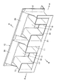
バッフル10は、図4、6〜9に示すように、例えば樹脂成形品からなり、左右方向に長い形状となっている。バッフル10の左右方向中央部には、図3に示すように、温風通路R2からの温風をデフロスト吹出口4b方向に導くための中央温風ガイド筒部(温風ガイド部)11が上下方向に延びるように設けられている。中央温風ガイド筒部11は、前後方向に長い断面を有する角筒状であるが、断面形状は円形や楕円形等であってもよい。
As shown in FIGS. 4 and 6 to 9, the
図5に示すように、中央温風ガイド筒部11の上端部は、前側へ行くほど上に位置するように傾斜している。中央温風ガイド筒部11の上下両側が開放されており、中央温風ガイド筒部11の内部を温風が流通可能となっている。尚、この実施形態では、バッフル10を一体成形することができるように形状設定しているが、これに限らず、複数の部材を組み合わせてバッフル10を構成してもよい。
As shown in FIG. 5, the upper end portion of the central hot air
また、バッフル10の右側部には、温風通路R2からの温風をデフロスト吹出口4b方向に導くための右側温風ガイド凹部(温風ガイド部)12が設けられている。右側温風ガイド凹部12は、左に向けて窪み、上下方向に延びる形状となっている。さらに、バッフル10の左側部には、温風通路R2からの温風をデフロスト吹出口4b方向に導くための左側温風ガイド凹部(温風ガイド部)13が設けられている。左側温風ガイド凹部13は、右に向けて窪み、上下方向に延びる形状となっている。これにより、ケーシング4の内部には、3つの温風ガイド部が左右方向に間隔をあけて設けられることになり、左右方向の中央部、左側及び右側の3箇所において温風を所定方向に導くことができる。
Further, on the right side portion of the
右側温風ガイド凹部12及び左側温風ガイド凹部13の上縁部はそれぞれ前側へ行くほど上に位置するように傾斜している。右側温風ガイド凹部12及び左側温風ガイド凹部13は、上下両側が開放されて内部を温風が流通可能となっている。また、右側温風ガイド凹部12及び左側温風ガイド凹部13の前後方向の寸法(凹部の幅)は、左右方向の寸法(凹部の深さ)よりも長く設定されている。バッフル10をケーシング4の内部に組み付けた状態で、右側温風ガイド凹部12及び左側温風ガイド凹部13がそれぞれケーシング4の左側壁部内面及び右側壁部内面によって閉塞されて閉断面の通路が形成される。尚、右側温風ガイド凹部12及び左側温風ガイド凹部13の代わりに、中央温風ガイド筒部11のような上下方向に延びる筒部をそれぞれ設けてもよい。
The upper edge portions of the right-side hot
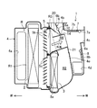
バッフル10の中央温風ガイド筒部11の右側には中央右側冷風ガイド筒部14が設けられ、左側には中央左側冷風ガイド筒部15が設けられている。図2に示すように、中央右側冷風ガイド筒部14及び中央左側冷風ガイド筒部15は、バイパス通路R3からの冷風を左右方向中央部のベント吹出口4c方向に導く冷風ガイド部であり、前後方向に延びている。つまり、中央右側冷風ガイド筒部14及び中央左側冷風ガイド筒部15と、中央温風ガイド筒部11、右側温風ガイド凹部12及び左側温風ガイド凹部13とは互いに異なる方向に延びている。また、中央右側冷風ガイド筒部14及び中央左側冷風ガイド筒部15の断面は上下方向に長い略矩形断面となっている。
A central right cold air
バッフル10の右側には、中央右側冷風ガイド筒部14から右側に離れた部分に、右側冷風ガイド筒部16が設けられている。右側冷風ガイド筒部16は、右側温風ガイド凹部12が形成された部分と一体化している。また、バッフル10の左側には、中央左側冷風ガイド筒部15から左側に離れた部分に、左側冷風ガイド筒部17が設けられている。左側冷風ガイド筒部17は、左側温風ガイド凹部13が形成された部分と一体化している。右側冷風ガイド筒部16及び左側冷風ガイド筒部17は、それぞれ、バイパス通路R3からの冷風を右側のベント吹出口4c方向及び左側のベント吹出口4c方向に導くための冷風ガイド部であり、中央右側冷風ガイド筒部14及び中央左側冷風ガイド筒部15と同様に、前後方向に延びるとともに、上下方向に長い略矩形断面を有している。
On the right side of the
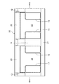
中央温風ガイド筒部11と、中央右側冷風ガイド筒部14と、中央左側冷風ガイド筒部15とが左右方向に隣接するように設けられているので、バッフル10をコンパクトにすることができる。また、右側温風ガイド凹部12の形成部位と右側冷風ガイド筒部16とが左右方向に隣接するように設けられており、左側温風ガイド凹部13の形成部位と左側冷風ガイド筒部17とが左右方向に隣接するように設けられているので、このことによっても、バッフル10をコンパクトにすることができる。
Since the central hot air
中央右側冷風ガイド筒部14、中央左側冷風ガイド筒部15、右側冷風ガイド筒部16及び左側冷風ガイド筒部17は、略同じ長さとされるとともに、断面積も略同じに設定されている。また、ケーシング4の内部において、4つの冷風ガイド部が左右方向に間隔をあけて設けられることになる。
The central right cold air
中央右側冷風ガイド筒部14、中央左側冷風ガイド筒部15、右側冷風ガイド筒部16及び左側冷風ガイド筒部17は、少なくともバッフル10の下側に設けられており、そこからバッフル10の上側に亘っている。そして、バッフル10の中央右側冷風ガイド筒部14と右側冷風ガイド筒部16との間には、図1に示すように温風通路R2からの温風と、バイパス通路R3からの冷風とを混合させるための右側温冷風混合通路18が設けられている。また、バッフル10の中央左側冷風ガイド筒部15と左側冷風ガイド筒部17との間には、温風通路R2からの温風と、バイパス通路R3からの冷風とを混合させるための左側温冷風混合通路19(図4参照)が設けられている。
The central right cold air
右側温冷風混合通路18及び左側温冷風混合通路19は、ちょうどエアミックス空間R4内に位置付けられており、その上流側が温風通路R2及びバイパス通路R3の下流端に連通するとともに、その下流側がエアミックス空間R4内において後方及び上方に開放されている。
The right side hot / cold
また、中央右側冷風ガイド筒部14、中央左側冷風ガイド筒部15、右側冷風ガイド筒部16及び左側冷風ガイド筒部17は、バッフル10における右側温冷風混合通路18及び左側温冷風混合通路19の流れ方向上流側(下側)に位置付けられているので、右側温冷風混合通路18及び左側温冷風混合通路19の流れ方向上流側が下流側に比べて絞られている。
Further, the central right cold air
バッフル10の上部には、バイパス通路R3からの冷風を下方へ導くように、後側へ行くほど下方へ延びる冷風側板部20、20が設けられている。冷風側板部20、20は、中央温風ガイド筒部11を挟むように配置されている。ケーシング4を上方から見たとき、冷風側板部20、20がデフロスト吹出口4bの内方に位置するように配置されている。これにより、冷風側板部20、20によって冷風をデフロスト吹出口4bから離れる方向に確実に導くことができる。
On the upper part of the
一方、バッフル10の下部には、温風通路R2からの温風がヒート吹出口4dへ向けて流れるのを阻止する温風側板部21が下方へ延びるように設けられている。温風側板部21の下端部は、ケーシング4の内部に底壁部から上方へ延びるように設けられている区画壁部4eの上部に接している。区画壁部4eは、ヒート吹出口4dと温風通路R2との間に配置されており、ヒート吹出口4dよりも上方まで延びている。バッフル10の温風側板部21とケーシング4の区画壁部4eとが連続することにより、温風を上方へ確実に導くことができる。
On the other hand, a warm air
次に、上記のように構成された車両用空調装置1の動作について説明する。冷風通路R1を流れる空調用空気は冷却用熱交換器2を通過することにより冷却用熱交換器2によって冷却されて冷風となる。この冷風が温風通路R2を流れると、加熱用熱交換器3を通過することにより加熱用熱交換器3によって加熱されて温風になる一方、バイパス通路R3を流れると冷風のまま下流側へ流れていく。そして、エアミックスダンパ5の動作によってエアミックス空間R4に流入する温風量及び冷風量が調整されてエアミックス空間R4で所望温度の空調風が生成される。フルコールドの場合には、温風通路R2を流れる風量が略0になる一方、フルホットの場合には、バイパス通路R3を流れる風量が略0になる。フルコールドとフルホットの間の中間域では、温風通路R2及びバイパス通路R3に空調用空気が流れる。
Next, operation | movement of the
温度コントロールが中間域にある場合、詳しくは、図1に示すようにバッフル10の右側温冷風混合通路18に対応する部分を通る縦断面図を参照すると、温風通路R2からの温風が上方へ流れてバッフル10の右側温冷風混合通路18に流入し、バイパス通路R3からの冷風が後方へ流れて右側温冷風混合通路18に流入する。このとき温風と冷風とは互いに交差する方向に流れていることから温風と冷風が衝突して混合が促進され、空調風が生成される。左側温冷風混合通路19においても同様である。生成された空調風は吹出モードに応じて、デフロスト吹出口4b、ベント吹出口4c、ヒート吹出口4dに供給される。尚、図1では冷風の流れと温風の流れを矢印で模式的に示している。
In the case where the temperature control is in the intermediate range, in detail, referring to the longitudinal sectional view passing through the portion corresponding to the right hot / cold
このとき、図2に示すように、車両用空調装置1におけるバッフル10の中央右側冷風ガイド筒部14に対応する部分を通る縦断面図を参照すると、バイパス通路R3からの冷風が後方へ流れてバッフル10の中央右側冷風ガイド筒部14に流入し、中央右側冷風ガイド筒部14によってベント吹出口4c方向に導かれるので、加熱用熱交換器3を通過していない勢いの強い冷風がデフロスト吹出口4b方向に向けて流れ難くなる。中央左側冷風ガイド筒部15、右側冷風ガイド筒部16及び左側冷風ガイド筒部17によっても同様に冷風を導くことができる。
At this time, as shown in FIG. 2, referring to a longitudinal sectional view passing through a portion corresponding to the central right cold air
このことに加えて、図3に示すように、車両用空調装置1におけるバッフル10の中央温風ガイド筒部11に対応する部分を通る縦断面図を参照すると、温風通路R2からの温風が上方へ流れてバッフル10の中央温風ガイド筒部11に流入し、中央温風ガイド筒部11によってデフロスト吹出口4b方向に導かれるので、デフロスト吹出口4bへの温風量が確保される。右側温風ガイド凹部12及び左側温風ガイド凹部13によっても同様に温風を導くことができる。以上のことにより、デフロスト吹出口4bから吹き出す空調風の温度低下が回避される。
In addition to this, referring to a longitudinal sectional view passing through a portion corresponding to the central hot air
また、冷風がバッフル10の中央右側冷風ガイド筒部14、中央左側冷風ガイド筒部15、右側冷風ガイド筒部16及び左側冷風ガイド筒部17によってベント吹出口4c方向に導かれるので、主に夏季に選択されるベントモード時にベント吹出口4cから吹き出す空調風の温度が低温になるとともに、低温の空調風の風量が十分に確保される。
Further, since the cold air is guided in the direction of the
また、中央右側冷風ガイド筒部14、中央左側冷風ガイド筒部15、右側冷風ガイド筒部16及び左側冷風ガイド筒部17がバッフル10の下側に位置することになるので、これらガイド筒部14〜17により冷風がベント吹出口4bに効率よく導かれる。
Further, since the central right cold air
また、温冷風混合通路18、19の流れ方向上流側の流路が中央右側冷風ガイド筒部14、中央左側冷風ガイド筒部15、右側冷風ガイド筒部16及び左側冷風ガイド筒部17によって絞られることになる。これにより、温冷風混合通路18、19に流入する温風の流速を高めて冷風との混合性が良好になる。また、温風が中央温風ガイド筒部11、右側温風ガイド凹部12及び左側温風ガイド凹部13に流入し易くなるので、中央温風ガイド筒部11、右側温風ガイド凹部12及び左側温風ガイド凹部13による効果がより顕著なものになる。
Further, the upstream and downstream flow paths of the hot and cold
また、バイパス通路R3からの冷風がバッフル10の冷風側板部20、20によってデフロスト吹出口4bから離れる方向に導かれるので、冷風がデフロスト吹出口4bに向けて流れ難くなり、デフロスト吹出口4bから吹き出す空調風の温度低下が回避される。
Further, since the cold air from the bypass passage R3 is guided in the direction away from the
また、バッフル10に温風側板部21を設けているので、温風通路R2からの温風がバッフル10の下部からヒート吹出口4dに向けて漏れにくくなる。これにより、バッフル10による温風のガイド効果が十分に得られるようになる。
Moreover, since the warm air
また、バッフル10に右側冷風ガイド筒部16及び左側冷風ガイド筒部17を設けているので、風量分配に不利な左右方向両側のベント吹出口4cに冷風を導くことができる。これにより、左右両側のベント吹出口4cから十分な量の冷風を供給することが可能になる。
Moreover, since the
以上説明したように、この実施形態1に係る車両用空調装置1によれば、温風及び冷風の合流部位に配設したバッフル10によって温風通路R2からの温風をデフロスト吹出口4b方向に導くことができるとともに、バイパス通路R3からの冷風をベント吹出口4c方向に導くことができる。これにより、デフロスト吹出口4bから吹き出す空調風の温度及びベント吹出口4cから吹き出す空調風の温度を共に適温にすることができる。よって、高い温度コントロール性能を得ることができ、快適性を向上させることができる。
As described above, according to the
本発明は、吹出モードがデフヒートモードにあるときに特に有効である。デフヒートモードでは、空調風がデフロスト吹出口4bに供給されるとともに、ヒート吹出口4dにも供給されるので、ケーシング4の内部では下流側領域において空調風の流れが上下両方向になる。このとき、バイパス通路R3が上側に位置しているので、冷風がデフロスタ吹出口4bに流れ易く、反対に、温風通路R2が下側に位置しているので、温風がヒート吹出口4dに流れ易くなる。このことで、上下の温度差、即ち、デフロスト吹出口4bに供給される空調風の温度(低くなる)と、ヒート吹出口4dに供給される空調風の温度(高くなる)との差が大きくなり、快適性に悪影響を与えることが考えられるが、本発明によればデフロスト吹出口4bに供給される空調風の温度をバッフル10によって高めることができるので、デフロスト吹出口4bに供給される空調風の温度と、ヒート吹出口4dに供給される空調風の温度との差を小さくすることができ、よって、快適性を向上させることができる。
The present invention is particularly effective when the blowing mode is in the differential heat mode. In the differential heat mode, the conditioned air is supplied to the
尚、デフロスト吹出口4b方向に導く温風量は、中央温風ガイド筒部11、右側温風ガイド凹部12及び左側温風ガイド凹部13の断面積を変更することによって容易に調整することができる。また、ベント吹出口4c方向に導く冷風量は、中央右側冷風ガイド筒部14、中央左側冷風ガイド筒部15、右側冷風ガイド筒部16及び左側冷風ガイド筒部17の断面積を変更することによって容易に調整することができる。
The amount of warm air guided in the direction of the
また、中央温風ガイド筒部11、右側温風ガイド凹部12及び左側温風ガイド凹部13のうち、いずれか1つまたは2つを省略してもよい。また、中央右側冷風ガイド筒部14、中央左側冷風ガイド筒部15、右側冷風ガイド筒部16及び左側冷風ガイド筒部17のうち、いずれか1つまたは複数を省略してもよい。
Moreover, you may abbreviate | omit any one or two among the center warm air
(実施形態2)
図10〜図12は、本発明の実施形態2に係る車両用空調装置1を示すものである。実施形態2の車両用空調装置1は、内外気2層流タイプの車両用空調装置1である点で実施形態1のものと異なっており、他の部分は実施形態1と同様であるため、以下、実施形態1と同じ部分については同じ符号を付して説明を省略し、異なる部位について詳細に説明する。
(Embodiment 2)
FIGS. 10-12 shows the
図示しないが、実施形態2の送風ユニットは、内気循環モード及び外気導入モードの他に、内気と外気とを同時に導入する内外気2層流モードにも切り替えることができるようになっている。この送風ユニットは従来から内外気2層流タイプの車両用空調装置1に使用されているものであるため、詳細な説明は省略する。内外気2層流モード時には、内気と外気とが別々の通路を流れるようになっている。内気循環モード、外気導入モード及び内外気2層流モードの切替は、従来から周知のオートエアコン制御によって行われる。
Although not shown, the blower unit of the second embodiment can be switched to an inside / outside air two-layer flow mode in which inside air and outside air are introduced simultaneously in addition to the inside air circulation mode and the outside air introduction mode. Since this blower unit is conventionally used in the
ケーシング4の内部には、上下方向中間部に上流側仕切板9aと下流側仕切板9bとが設けられている。上流側仕切板9aは、冷却用熱交換器2よりも上流側の冷風通路R1に配置され、該冷風通路R1を上下に2つに仕切っている。上流側仕切板9aの下流側端部は、冷却用熱交換器2の空気流入面に接近している。内外気2層流モード時には、上流側仕切板9aよりも下側に内気が導入される一方、上流側仕切板9aよりも上側に外気が導入されるが、内気循環モード時には、上流側仕切板9aよりも下側及び上側の両方に内気が導入され、また、外気導入モード時には、上流側仕切板9aよりも下側及び上側の両方に外気が導入される。
Inside the
下流側仕切板9bは、冷却用熱交換器2よりも下流側の冷風通路R1に配置され、該冷風通路R1を上下に2つに仕切っている。下流側仕切板9bの上流側端部は、冷却用熱交換器2の空気流出面に接近している。下流側仕切板9bの下流側端部は加熱用熱交換器3の空気流入面近傍まで延びており、これにより、温風通路が下側温風通路R2Aと上側温風通路R2Bとに仕切られる。
The
加熱用熱交換器3は、ケーシング4の内部の上下方向中間部において下側温風通路R2Aと上側温風通路R2Bとに跨がるように配設されている。加熱用熱交換器3の下方には、下側バイパス通路R3Aが形成されている。下側バイパス通路R3Aは後方へ延びた後、上方へ屈曲して延びている。また、加熱用熱交換器3の上方には、上側バイパス通路R3Bが形成されている。上側バイパス通路R3Bは後方へ延びている。
The
ヒートダンパ8は、開状態で図10に示すようになり、下側温風通路R2Aと上側温風通路R2Bとを区画するように作用する。これにより、下側温風通路R2Aからの温風及び下側バイパス通路R3Aからの冷風がヒート吹出口4dに供給される。ヒートダンパ8が閉状態にあるときには、閉塞板部8bが上下方向に延びる姿勢となるので、下側温風通路R2Aからの温風及び下側バイパス通路R3Aからの冷風が上方へ流れることになる。
The
エアミックスダンパ5は、上側バイパス通路R3Bを開閉する複数の第1ルーバ5dと、下側バイパス通路R3Aを開閉する複数の第2ルーバ5eと、上側温風通路R2Bを開閉する複数の第3ルーバ5fと、下側温風通路R2Aを開閉する複数の第4ルーバ5gとを有しており、第1〜第4ルーバ5d〜5gは枠部材5aに回動可能に支持されている。また、第1〜第4ルーバ5d〜5gは連動するように構成されている。
The
第1ルーバ5dは、上側バイパス通路R3Bの上流端を開いたときに、空気流れ方向下流側へ行くほど下に位置するように傾斜している。第2ルーバ5eは、下側バイパス通路R3Aの上流端を開いたときに、空気流れ方向下流側へ行くほど下に位置するように傾斜している。第3ルーバ5fは、上側温風通路R2Bの上流端を開いたときに、空気流れ方向下流側へ行くほど上に位置するように傾斜している。第4ルーバ5gは、下側温風通路R2Aの上流端を開いたときに、空気流れ方向下流側へ行くほど上に位置するように傾斜している。
When the upstream end of the upper bypass passage R3B is opened, the
実施形態2のバッフル30は、ケーシング4の内部において上側バイパス通路R3Bからの冷風と、下方から流れてくる温風との合流部位に配設されている。バッフル30の基本的な構成は、実施形態1と同じであり、内外気2層流タイプとするために形状変更が行われている。すなわち、図13に示すように、実施形態2のバッフル30には、中央温風ガイド筒部31、右側温風ガイド凹部32、左側温風ガイド凹部33、中央右側冷風ガイド筒部34、中央左側冷風ガイド筒部35、右側冷風ガイド筒部36及び左側冷風ガイド筒部37が設けられている。また、バッフル30の中央右側冷風ガイド筒部34と右側冷風ガイド筒部36との間には、温風と冷風とを混合させるための右側温冷風混合通路38が設けられている。また、バッフル30の中央左側冷風ガイド筒部35と左側冷風ガイド筒部37との間にも温風と冷風とを混合させるための左側温冷風混合通路39が設けられている。
The
バッフル30の上部には、上側バイパス通路R3Bからの冷風がデフロスト吹出口4bに直接向かわないようにするための冷風側板部40が設けられている。一方、バッフル30の下部には、後側へ延びる延出板部41が設けられている。延出板部41は、後側へ行くほど下に位置するように湾曲形成されている。延出板部41の後端部はケーシング4の内面に当接している。
On the upper part of the
実施形態2の車両用空調装置1によれば、実施形態1のものと同様に、バッフル30によって温風通路R2A、R2Bからの温風をデフロスト吹出口4b方向に導くことができるとともに、上側バイパス通路R3Bからの冷風をベント吹出口4c方向に導くことができる。これにより、デフロスト吹出口4bから吹き出す空調風の温度及びベント吹出口4cから吹き出す空調風の温度を共に適温にすることができる。よって、高い温度コントロール性能を得ることができ、快適性を向上させることができる。
According to the
また、内外気2層流モードにすることで、冬季には比較的乾燥した外気をデフロスト吹出口4bに供給してフロントウインドガラスの曇りを良好に晴らしながら、比較的暖かい内気をヒート吹出口4dに供給して暖房効率を向上させることができる。
Further, by setting the inside / outside air two-layer flow mode, in the winter season, relatively dry outside air is supplied to the
(実施形態3)
図19〜図21は、本発明の実施形態3に係る車両用空調装置1を示すものである。実施形態3の車両用空調装置1は、実施形態1と同様な1層流タイプの車両用空調装置1であるが、バイパス通路R3からの冷風をベント吹出口4cへ向かう方向(ベント吹出口4c方向)とヒート吹出口4dへ向かう方向(ヒート吹出口4d方向)にも導くように構成されている点で実施形態1のものと異なっており、他の部分は実施形態1と同様であるため、以下、実施形態1と同じ部分については同じ符号を付して説明を省略し、異なる部位について詳細に説明する。
(Embodiment 3)
FIGS. 19-21 shows the
実施形態3では、図19に示すように、バッフル10の右側温冷風混合通路18の底壁部が後側へ向かって下降傾斜するように形成されている。左側温冷風混合通路19の底壁部も同様である。これにより、バイパス通路R3からの冷風をヒート吹出口4dへ向かう方向へも導くことができるので、デフロスト吹出口4bから吹き出す空調風の温度及びベント吹出口4cから吹き出す空調風の温度を共に適温にすることができる。よって、高い温度コントロール性能を得ることができ、快適性を向上させることができる。
In the third embodiment, as shown in FIG. 19, the bottom wall portion of the right hot / cold
また、バイパス通路R3からの冷風の流れ方向は右側温冷風混合通路18及び左側温冷風混合通路19の壁部の形状によって設定することができ、バイパス通路R3からの冷風をヒート吹出口4d方向のみに導くようにしてもよい。
Further, the flow direction of the cold air from the bypass passage R3 can be set by the shape of the wall portion of the right side hot / cold
尚、上記実施形態1〜3では、エアミックスダンパ5をルーバダンパとしているが、これに限らず、例えばフィルムダンパ、ロータリダンパ等の各種ダンパを使用することができる。また、吹出モードを切り替えるためのダンパ6〜8についても、例えば、ロータリダンパ等の各種ダンパを使用することができる。
In the first to third embodiments, the
また、上記実施形態1〜3では、送風ユニットが助手席前方に配設されているセミセンタユニットに本発明を適用した場合について説明したが、これに限らず、送風ユニットを車両の左右方向中央部に配設したフルセンタユニットに本発明を適用してもよい。 Moreover, although the said Embodiment 1-3 demonstrated the case where this invention was applied to the semi center unit with which the ventilation unit is arrange | positioned ahead of a passenger seat, it is not restricted to this, A ventilation unit is the center of the left-right direction of a vehicle You may apply this invention to the full center unit arrange | positioned in the part.
上述の実施形態はあらゆる点で単なる例示に過ぎず、限定的に解釈してはならない。さらに、特許請求の範囲の均等範囲に属する変形や変更は、全て本発明の範囲内のものである。 The above-described embodiment is merely an example in all respects and should not be interpreted in a limited manner. Further, all modifications and changes belonging to the equivalent scope of the claims are within the scope of the present invention.
以上説明したように、本発明に係る車両用空調装置は、例えば自動車に搭載することができる。 As described above, the vehicle air conditioner according to the present invention can be mounted on, for example, an automobile.
1 車両用空調装置
2 冷却用熱交換器
3 加熱用熱交換器
4 ケーシング
4b デフロスト吹出口
4c ベント吹出口
4d ヒート吹出口
10 バッフル
11 中央温風ガイド筒部(温風ガイド部)
12 右側温風ガイド凹部(温風ガイド部)
13 左側温風ガイド凹部(温風ガイド部)
14 中央右側冷風ガイド筒部(冷風ガイド部)
15 中央左側冷風ガイド筒部(冷風ガイド部)
16 右側冷風ガイド筒部(冷風ガイド部)
17 左側冷風ガイド筒部(冷風ガイド部)
18 右側温冷風混合通路
19 左側温冷風混合通路
20 冷風側板部
21 温風側板部
R1 冷風通路
R2 温風通路
R3 バイパス通路
R4 エアミックス空間
DESCRIPTION OF
12 Right side hot air guide recess (hot air guide part)
13 Left hot air guide recess (hot air guide)
14 Center right cold wind guide tube (cold wind guide)
15 Center left cold air guide tube (cold air guide)
16 Right side cold air guide tube (cold air guide)
17 Left cold air guide tube (cold air guide)
18 Right side hot / cold
Claims (7)
空調用空気を加熱する加熱用熱交換器と、
上記冷却用熱交換器が配置される冷風通路と、該冷風通路の下流側に連通し、上記加熱用熱交換器が配置される温風通路と、上記冷風通路の下流側から分岐して上記温風通路をバイパスして延びるバイパス通路と、上記温風通路及び上記バイパス通路の下流側が連通するエアミックス空間と、該エアミックス空間に連通するデフロスト吹出口、ベント吹出口及びヒート吹出口とが設けられたケーシングと、
上記ケーシングの内部に配設され、上記温風通路及び上記バイパス通路の下流側からそれぞれ上記エアミックス空間に流入する温風量及び冷風量を調整するエアミックスダンパとを備えた車両用空調装置において、
上記ケーシングの内部には、温風及び冷風の合流部位にバッフルが配設され、
上記バッフルには、上記温風通路からの温風を上記デフロスト吹出口方向に導く温風ガイド部と、上記バイパス通路からの冷風を上記ベント吹出口方向及び上記ヒート吹出口方向の少なくとも一方に導く冷風ガイド部とが設けられていることを特徴とする車両用空調装置。 A cooling heat exchanger for cooling the air-conditioning air;
A heat exchanger for heating air for air conditioning,
The cold air passage in which the cooling heat exchanger is disposed, the hot air passage in communication with the downstream side of the cold air passage, the hot air passage in which the heating heat exchanger is disposed, and the downstream from the cold air passage. A bypass passage extending by bypassing the hot air passage, an air mix space communicating with the hot air passage and the downstream side of the bypass passage, a defrost outlet, a vent outlet and a heat outlet communicating with the air mix space. A provided casing;
An air conditioner for a vehicle provided with an air mix damper that is arranged inside the casing and adjusts the amount of hot air and the amount of cold air flowing into the air mix space from the downstream side of the hot air passage and the bypass passage, respectively.
Inside the casing, a baffle is disposed at a confluence site of hot air and cold air,
The baffle guides the hot air from the hot air passage toward the defrost outlet, and guides the cold air from the bypass passage to at least one of the vent outlet direction and the heat outlet direction. An air conditioner for a vehicle, characterized in that a cold air guide part is provided.
上記ベント吹出口は上記デフロスト吹出口の下方に設けられ、
上記冷風ガイド部は、上記バッフルの下側に設けられていることを特徴とする車両用空調装置。 In the vehicle air conditioner according to claim 1,
The vent outlet is provided below the defrost outlet,
The vehicle air conditioner, wherein the cold air guide portion is provided below the baffle.
上記バッフルには、上記温風通路からの温風と、上記バイパス通路からの冷風とを混合させるための温冷風混合通路が設けられ、
上記冷風ガイド部は、筒状に形成されるとともに、上記バッフルにおける上記温冷風混合通路の流れ方向上流側に位置付けられることを特徴とする車両用空調装置。 The vehicle air conditioner according to claim 1 or 2,
The baffle is provided with a hot / cold air mixing passage for mixing hot air from the hot air passage and cold air from the bypass passage,
The vehicle air conditioner is characterized in that the cold air guide portion is formed in a cylindrical shape and is positioned on the upstream side in the flow direction of the hot and cold air mixing passage in the baffle.
上記デフロスト吹出口は、上記ケーシングの上壁部に設けられ、
上記バッフルには、上記バイパス通路からの冷風を下方へ導くように延びる冷風側板部が設けられていることを特徴とする車両用空調装置。 In the vehicle air conditioner according to any one of claims 1 to 3,
The defrost outlet is provided on the upper wall of the casing,
A vehicular air conditioner, wherein the baffle is provided with a cold air side plate portion extending so as to guide the cold air from the bypass passage downward.
上記ヒート吹出口は、上記デフロスト吹出口及び上記ベント吹出口の下方に設けられ、
上記バッフルの下部には、上記温風通路からの温風が上記ヒート吹出口へ向けて流れるのを阻止する温風側板部が下方へ延びるように設けられていることを特徴とする車両用空調装置。 In the vehicle air conditioner according to any one of claims 1 to 4,
The heat outlet is provided below the defrost outlet and the vent outlet,
A vehicular air conditioner characterized in that a hot air side plate portion for preventing hot air from the hot air passage from flowing toward the heat outlet is provided below the baffle so as to extend downward. apparatus.
上記ベント吹出口は、上記ケーシングの車幅方向両側に設けられ、
上記冷風ガイド部は、上記バッフルの車幅方向両側に設けられ、上記車幅方向両側のベント吹出口方向に冷風を導くことを特徴とする車両用空調装置。 In the vehicle air conditioner according to any one of claims 1 to 5,
The vent outlet is provided on both sides of the casing in the vehicle width direction,
The vehicle air conditioner is characterized in that the cold air guide portions are provided on both sides of the baffle in the vehicle width direction and guide the cold air toward the vent outlets on both sides of the vehicle width direction.
上記温風ガイド部と上記冷風ガイド部とは、互いに異なる方向に延びていることを特徴とする車両用空調装置。 In the vehicle air conditioner according to any one of claims 1 to 6,
The vehicle air conditioner characterized in that the hot air guide portion and the cold air guide portion extend in different directions.
Priority Applications (3)
| Application Number | Priority Date | Filing Date | Title |
|---|---|---|---|
| JP2015238494A JP6734641B2 (en) | 2015-12-07 | 2015-12-07 | Vehicle air conditioner |
| EP16872582.8A EP3363665B1 (en) | 2015-12-07 | 2016-10-13 | Air conditioning device for vehicle |
| PCT/JP2016/004563 WO2017098680A1 (en) | 2015-12-07 | 2016-10-13 | Air conditioning device for vehicle |
Applications Claiming Priority (1)
| Application Number | Priority Date | Filing Date | Title |
|---|---|---|---|
| JP2015238494A JP6734641B2 (en) | 2015-12-07 | 2015-12-07 | Vehicle air conditioner |
Publications (2)
| Publication Number | Publication Date |
|---|---|
| JP2017105235A true JP2017105235A (en) | 2017-06-15 |
| JP6734641B2 JP6734641B2 (en) | 2020-08-05 |
Family
ID=59012953
Family Applications (1)
| Application Number | Title | Priority Date | Filing Date |
|---|---|---|---|
| JP2015238494A Active JP6734641B2 (en) | 2015-12-07 | 2015-12-07 | Vehicle air conditioner |
Country Status (3)
| Country | Link |
|---|---|
| EP (1) | EP3363665B1 (en) |
| JP (1) | JP6734641B2 (en) |
| WO (1) | WO2017098680A1 (en) |
Cited By (2)
| Publication number | Priority date | Publication date | Assignee | Title |
|---|---|---|---|---|
| CN110481265A (en) * | 2018-05-15 | 2019-11-22 | 法雷奥日本株式会社 | Air conditioner for vehicles |
| CN112292274A (en) * | 2018-06-29 | 2021-01-29 | 三菱重工制冷空调系统株式会社 | Air conditioner for vehicle |
Families Citing this family (2)
| Publication number | Priority date | Publication date | Assignee | Title |
|---|---|---|---|---|
| KR102456849B1 (en) * | 2017-12-15 | 2022-10-21 | 한온시스템 주식회사 | Air conditioner for vehicles |
| US11458813B2 (en) * | 2019-12-10 | 2022-10-04 | Valeo North America, Inc. | Heating, ventilation, and air conditioning (HVAC) assembly for managing air mixing door kinematics and method for managing the same |
Citations (6)
| Publication number | Priority date | Publication date | Assignee | Title |
|---|---|---|---|---|
| JP2004237940A (en) * | 2003-02-10 | 2004-08-26 | Zexel Valeo Climate Control Corp | Air conditioner for automobile |
| US20060027354A1 (en) * | 2004-07-16 | 2006-02-09 | Valeo Climatisation S.A. | Temperature control system in a heating, air conditioning and ventilation device |
| JP2007125955A (en) * | 2005-11-02 | 2007-05-24 | Valeo Thermal Systems Japan Corp | Air conditioning device for vehicle |
| WO2009075255A1 (en) * | 2007-12-10 | 2009-06-18 | Calsonic Kansei Corporation | Air conditioner for automobile |
| JP2009143330A (en) * | 2007-12-12 | 2009-07-02 | Calsonic Kansei Corp | Air conditioner for automobile |
| US20150343877A1 (en) * | 2014-05-30 | 2015-12-03 | Halla Visteon Climate Control Corp. | Warm or cold air channel with slots to optimise control curves |
Family Cites Families (2)
| Publication number | Priority date | Publication date | Assignee | Title |
|---|---|---|---|---|
| FR2805217B1 (en) * | 2000-02-22 | 2002-06-28 | Valeo Climatisation | AIR CONDITIONING DEVICE FOR VEHICLE |
| JP5972736B2 (en) * | 2012-09-21 | 2016-08-17 | 株式会社ケーヒン | Air conditioner for vehicles |
-
2015
- 2015-12-07 JP JP2015238494A patent/JP6734641B2/en active Active
-
2016
- 2016-10-13 WO PCT/JP2016/004563 patent/WO2017098680A1/en active Application Filing
- 2016-10-13 EP EP16872582.8A patent/EP3363665B1/en active Active
Patent Citations (6)
| Publication number | Priority date | Publication date | Assignee | Title |
|---|---|---|---|---|
| JP2004237940A (en) * | 2003-02-10 | 2004-08-26 | Zexel Valeo Climate Control Corp | Air conditioner for automobile |
| US20060027354A1 (en) * | 2004-07-16 | 2006-02-09 | Valeo Climatisation S.A. | Temperature control system in a heating, air conditioning and ventilation device |
| JP2007125955A (en) * | 2005-11-02 | 2007-05-24 | Valeo Thermal Systems Japan Corp | Air conditioning device for vehicle |
| WO2009075255A1 (en) * | 2007-12-10 | 2009-06-18 | Calsonic Kansei Corporation | Air conditioner for automobile |
| JP2009143330A (en) * | 2007-12-12 | 2009-07-02 | Calsonic Kansei Corp | Air conditioner for automobile |
| US20150343877A1 (en) * | 2014-05-30 | 2015-12-03 | Halla Visteon Climate Control Corp. | Warm or cold air channel with slots to optimise control curves |
Cited By (3)
| Publication number | Priority date | Publication date | Assignee | Title |
|---|---|---|---|---|
| CN110481265A (en) * | 2018-05-15 | 2019-11-22 | 法雷奥日本株式会社 | Air conditioner for vehicles |
| CN112292274A (en) * | 2018-06-29 | 2021-01-29 | 三菱重工制冷空调系统株式会社 | Air conditioner for vehicle |
| CN112292274B (en) * | 2018-06-29 | 2024-01-05 | 三菱重工制冷空调系统株式会社 | Air conditioner for vehicle |
Also Published As
| Publication number | Publication date |
|---|---|
| JP6734641B2 (en) | 2020-08-05 |
| EP3363665B1 (en) | 2019-12-04 |
| EP3363665A4 (en) | 2018-12-12 |
| WO2017098680A1 (en) | 2017-06-15 |
| EP3363665A1 (en) | 2018-08-22 |
Similar Documents
| Publication | Publication Date | Title |
|---|---|---|
| JP5569513B2 (en) | Air conditioner for vehicles | |
| JP5639800B2 (en) | Air conditioner for vehicles | |
| JP5712002B2 (en) | Air conditioner for vehicles | |
| JP5667400B2 (en) | Heat exchanger used in vehicle air conditioners | |
| JP2009286286A (en) | Vehicular air conditioner | |
| JP2009202687A (en) | Vehicular air conditioner | |
| WO2017098680A1 (en) | Air conditioning device for vehicle | |
| JP2008094187A (en) | Vehicular air conditioner for vehicle | |
| JP2014046805A (en) | Air conditioner for vehicle | |
| JP2008094251A (en) | Vehicular air conditioner | |
| JP2016002949A (en) | Air conditioner for vehicle | |
| JP2010018248A (en) | Air conditioner for vehicle | |
| JP5719140B2 (en) | Air conditioner for vehicles | |
| JP6371533B2 (en) | Air conditioner for vehicles | |
| JP2018144532A (en) | Air conditioning device for vehicle | |
| JP4433169B2 (en) | Air conditioner for vehicles | |
| JP6810618B2 (en) | Vehicle air conditioner | |
| JP4134846B2 (en) | Air conditioner for vehicles | |
| JP2002002250A (en) | Air conditioner for vehicle | |
| JP6420531B2 (en) | Air conditioner for vehicles | |
| JP6444742B2 (en) | Air conditioner for vehicles | |
| JP4624773B2 (en) | Air conditioner for vehicles | |
| JP2004256048A (en) | Air conditioner for vehicle | |
| JP7169124B2 (en) | vehicle air conditioner | |
| JP7169123B2 (en) | vehicle air conditioner |
Legal Events
| Date | Code | Title | Description |
|---|---|---|---|
| A621 | Written request for application examination |
Free format text: JAPANESE INTERMEDIATE CODE: A621 Effective date: 20181206 |
|
| A131 | Notification of reasons for refusal |
Free format text: JAPANESE INTERMEDIATE CODE: A131 Effective date: 20191112 |
|
| A521 | Request for written amendment filed |
Free format text: JAPANESE INTERMEDIATE CODE: A523 Effective date: 20200109 |
|
| A131 | Notification of reasons for refusal |
Free format text: JAPANESE INTERMEDIATE CODE: A131 Effective date: 20200303 |
|
| A521 | Request for written amendment filed |
Free format text: JAPANESE INTERMEDIATE CODE: A523 Effective date: 20200403 |
|
| TRDD | Decision of grant or rejection written | ||
| A01 | Written decision to grant a patent or to grant a registration (utility model) |
Free format text: JAPANESE INTERMEDIATE CODE: A01 Effective date: 20200616 |
|
| A61 | First payment of annual fees (during grant procedure) |
Free format text: JAPANESE INTERMEDIATE CODE: A61 Effective date: 20200710 |
|
| R150 | Certificate of patent or registration of utility model |
Ref document number: 6734641 Country of ref document: JP Free format text: JAPANESE INTERMEDIATE CODE: R150 |
|
| R250 | Receipt of annual fees |
Free format text: JAPANESE INTERMEDIATE CODE: R250 |