JP2017104062A - Agricultural equipment and agricultural house using the same - Google Patents

Agricultural equipment and agricultural house using the same Download PDF

Info

Publication number
JP2017104062A
JP2017104062A JP2015241434A JP2015241434A JP2017104062A JP 2017104062 A JP2017104062 A JP 2017104062A JP 2015241434 A JP2015241434 A JP 2015241434A JP 2015241434 A JP2015241434 A JP 2015241434A JP 2017104062 A JP2017104062 A JP 2017104062A
Authority
JP
Japan
Prior art keywords
curtain
agricultural
winding shaft
frames
frame
Prior art date
Legal status (The legal status is an assumption and is not a legal conclusion. Google has not performed a legal analysis and makes no representation as to the accuracy of the status listed.)
Granted
Application number
JP2015241434A
Other languages
Japanese (ja)
Other versions
JP6741981B2 (en
Inventor
太一 濱塚
Taichi Hamazuka
太一 濱塚
谷澤 孝欣
Takayoshi Tanizawa
孝欣 谷澤
さつき 青山
Satsuki Aoyama
さつき 青山
尚史 児玉
Hisafumi Kodama
尚史 児玉
小泉 豪章
Toshiaki Koizumi
豪章 小泉
岩野 洋
Hiroshi Iwano
洋 岩野
武志 河野
Takeshi Kono
武志 河野
Current Assignee (The listed assignees may be inaccurate. Google has not performed a legal analysis and makes no representation or warranty as to the accuracy of the list.)
Panasonic Intellectual Property Management Co Ltd
Original Assignee
Panasonic Intellectual Property Management Co Ltd
Priority date (The priority date is an assumption and is not a legal conclusion. Google has not performed a legal analysis and makes no representation as to the accuracy of the date listed.)
Filing date
Publication date
Application filed by Panasonic Intellectual Property Management Co Ltd filed Critical Panasonic Intellectual Property Management Co Ltd
Priority to JP2015241434A priority Critical patent/JP6741981B2/en
Publication of JP2017104062A publication Critical patent/JP2017104062A/en
Application granted granted Critical
Publication of JP6741981B2 publication Critical patent/JP6741981B2/en
Active legal-status Critical Current
Anticipated expiration legal-status Critical

Links

Images

Classifications

    • YGENERAL TAGGING OF NEW TECHNOLOGICAL DEVELOPMENTS; GENERAL TAGGING OF CROSS-SECTIONAL TECHNOLOGIES SPANNING OVER SEVERAL SECTIONS OF THE IPC; TECHNICAL SUBJECTS COVERED BY FORMER USPC CROSS-REFERENCE ART COLLECTIONS [XRACs] AND DIGESTS
    • Y02TECHNOLOGIES OR APPLICATIONS FOR MITIGATION OR ADAPTATION AGAINST CLIMATE CHANGE
    • Y02ATECHNOLOGIES FOR ADAPTATION TO CLIMATE CHANGE
    • Y02A40/00Adaptation technologies in agriculture, forestry, livestock or agroalimentary production
    • Y02A40/10Adaptation technologies in agriculture, forestry, livestock or agroalimentary production in agriculture
    • Y02A40/25Greenhouse technology, e.g. cooling systems therefor
    • YGENERAL TAGGING OF NEW TECHNOLOGICAL DEVELOPMENTS; GENERAL TAGGING OF CROSS-SECTIONAL TECHNOLOGIES SPANNING OVER SEVERAL SECTIONS OF THE IPC; TECHNICAL SUBJECTS COVERED BY FORMER USPC CROSS-REFERENCE ART COLLECTIONS [XRACs] AND DIGESTS
    • Y02TECHNOLOGIES OR APPLICATIONS FOR MITIGATION OR ADAPTATION AGAINST CLIMATE CHANGE
    • Y02PCLIMATE CHANGE MITIGATION TECHNOLOGIES IN THE PRODUCTION OR PROCESSING OF GOODS
    • Y02P60/00Technologies relating to agriculture, livestock or agroalimentary industries
    • Y02P60/14Measures for saving energy, e.g. in green houses

Landscapes

  • Greenhouses (AREA)

Abstract

PROBLEM TO BE SOLVED: To provide agricultural equipment capable of smoothly opening and closing a curtain by suppressing winding deviation of the curtain, and also provide an agricultural house using the same.SOLUTION: According to the present invention, agricultural equipment 1 comprises a plurality of frames 2, a curtain 3, a driving device 4, and an anti-vibration device 5. Each of the plurality of frames 2 is formed in an inverted U-shape and comprises a pair of strut portions 21 and a connecting portion 22 connecting the upper ends of the paired strut portions 21 to each other. The curtain 3 is disposed outside the plurality of frames 2 that separately stand in a direction intersecting the plane surrounded by the frame 2, and its lower end portion 30 moves along the plurality of frames 2. The driving device 4 rotates a winding shaft 31 attached to the lower end portion 30 of the curtain 3. The anti-vibration device 5 keeps the winding shaft 31 horizontal.SELECTED DRAWING: Figure 1

Description

本発明は、農業用設備、及びこれを用いた農業用ハウスに関する。   The present invention relates to an agricultural facility and an agricultural house using the facility.

従来、開閉可能なカーテンを備えた農業用ハウス(ビニールハウス)がある(例えば、特許文献1参照)。特許文献1に記載の農業用ハウスでは、カーテンの下縁に設けられた巻取軸を回転させて、巻取軸にカーテンを巻き取ることでカーテンを開け、巻取軸からカーテンを繰り出すことでカーテンを閉じている。   Conventionally, there is an agricultural house (vinyl house) provided with a curtain that can be opened and closed (see, for example, Patent Document 1). In the agricultural house described in Patent Document 1, the winding shaft provided on the lower edge of the curtain is rotated, the curtain is wound around the winding shaft, the curtain is opened, and the curtain is fed out from the winding shaft. The curtain is closed.

特開平11−299365号公報JP-A-11-299365

特許文献1に記載の構成において、巻取軸にカーテンを巻き取る際に、巻取軸の軸方向において、カーテンの巻取り量が異なるために巻ずれが発生し、カーテンのスムーズな開閉が困難となるおそれがあった。   In the configuration described in Patent Document 1, when the curtain is wound around the take-up shaft, the winding amount of the curtain is different in the axial direction of the take-up shaft, so that winding deviation occurs and it is difficult to smoothly open and close the curtain. There was a risk of becoming.

本発明は、上記事由に鑑みてなされており、その目的は、カーテンの巻ずれを抑制し、カーテンをスムーズに開閉することが可能な農業用設備、及びこれを用いた農業用ハウスを提供することにある。   The present invention has been made in view of the above-mentioned reasons, and an object of the present invention is to provide an agricultural facility capable of suppressing the winding of the curtain and opening and closing the curtain smoothly, and an agricultural house using the same. There is.

本発明の農業用設備は、一対の支柱部、及び前記一対の支柱部の上端同士を連結する連結部を有する逆U字状に形成された複数のフレームと、前記フレームが囲む面と交差する方向に離れて立てられる前記複数のフレームの外側に配置され、下端部が前記複数のフレームに沿って移動するカーテンと、前記カーテンの前記下端部に取り付けられる巻取軸を回転させる駆動装置と、前記巻取軸を水平に保つ振れ止め装置とを備えることを特徴とする。   The agricultural equipment according to the present invention intersects a plurality of frames formed in an inverted U shape having a pair of struts and a connecting part that connects upper ends of the pair of struts, and a surface surrounded by the frame. A curtain that is arranged outside the plurality of frames that are set apart in a direction and whose lower end moves along the plurality of frames, and a driving device that rotates a winding shaft attached to the lower end of the curtain; And a steady rest device for keeping the winding shaft horizontal.

本発明の農業用ハウスは、上記の農業用設備と、前記農業用設備の前記複数のフレームを、前記複数のフレームとの間に隙間を空けて覆う被覆材を有するハウス本体とを備えることを特徴とする。   An agricultural house according to the present invention includes the agricultural equipment described above and a house body having a covering material that covers the plurality of frames of the agricultural equipment with a gap between the plurality of frames. Features.

本発明の農業用設備、及びこれを用いた農業用ハウスでは、カーテンの巻ずれを抑制し、カーテンをスムーズに開閉することができるという効果がある。   In the agricultural equipment of the present invention and the agricultural house using the same, there is an effect that curling of the curtain can be suppressed and the curtain can be opened and closed smoothly.

実施形態に係る農業用設備の斜視図である。It is a perspective view of the equipment for agriculture concerning an embodiment. 実施形態に係る農業用設備の結合部材の正面図である。It is a front view of the coupling member of the agricultural facility according to the embodiment. 実施形態に係る農業用設備の結合部材の別構成の正面図である。It is a front view of another composition of a coupling member of agricultural facilities concerning an embodiment. 実施形態に係る農業用設備の結合部材の別構成の正面図である。It is a front view of another composition of a coupling member of agricultural facilities concerning an embodiment. 実施形態に係る農業用設備の駆動装置の外観図である。It is an external view of the drive device of the agricultural facility which concerns on embodiment. 実施形態に係る農業用設備の噴霧装置の側面図である。It is a side view of the spraying apparatus of the agricultural equipment which concerns on embodiment. 実施形態に係る農業用設備の散水装置の斜視図である。It is a perspective view of the watering apparatus of the agricultural equipment which concerns on embodiment. 比較例に係る農業用設備の側面図である。It is a side view of the agricultural equipment which concerns on a comparative example. 実施形態に係る農業用設備の側面図である。It is a side view of the equipment for agriculture concerning an embodiment. 実施形態に係る農業用ハウスの斜視図である。It is a perspective view of the agricultural house which concerns on embodiment. 実施形態に係る農業用ハウスの正面図である。It is a front view of the agricultural house which concerns on embodiment. 実施形態に係る農業用設備の第1変形例の斜視図である。It is a perspective view of the 1st modification of the equipment for agriculture concerning an embodiment. 図13Aは、実施形態の農業用設備の第2変形例において、巻取軸に帯状部材を巻き取った状態の側面図である。図13Bは、実施形態に係る農業用設備の第2変形例において、巻取軸から帯状部材が繰り出された状態の側面図である。FIG. 13A is a side view of a state where a belt-like member is wound around a winding shaft in a second modification of the agricultural facility of the embodiment. FIG. 13B is a side view of a state in which the belt-shaped member is drawn from the winding shaft in the second modification of the agricultural facility according to the embodiment.

以下、本発明の実施の形態を図面に基づいて説明する。以下の実施形態は、一般に農業用設備、及びこれを用いた農業用ハウスに関し、より詳細には農作物の栽培に用いられる農業用設備、及びこれを用いた農業用ハウスに関する。なお、以下の実施形態において説明する各図は、模式的な図であり、構成要素の寸法比が必ずしも実際の寸法比を反映しているとは限らない。   Hereinafter, embodiments of the present invention will be described with reference to the drawings. The following embodiments generally relate to an agricultural facility and an agricultural house using the same, and more particularly to an agricultural facility used for cultivation of agricultural products and an agricultural house using the same. In addition, each figure demonstrated in the following embodiment is a typical figure, and the dimension ratio of a component does not necessarily reflect the actual dimension ratio.

(実施形態)
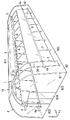
図1に本実施形態の農業用設備1の斜視図を示す。まず、本実施形態の農業用設備1の概要について説明する。
(Embodiment)
FIG. 1 shows a perspective view of an agricultural facility 1 of the present embodiment. First, the outline | summary of the agricultural equipment 1 of this embodiment is demonstrated.

本実施形態の農業用設備1は、ハウス本体8(図10参照)の内部において、植物の育成場である圃場を囲うように設けられる。   The agricultural equipment 1 of the present embodiment is provided inside the house body 8 (see FIG. 10) so as to surround a farm field that is a plant growth field.

本実施形態の農業用設備1は、複数のフレーム2と、カーテン3と、駆動装置4と、振れ止め装置5とを備えている。複数のフレーム2の各々は、一対の支柱部21、及び一対の支柱部21の上端同士を連結する連結部22を有する逆U字状に形成されている。カーテン3は、フレーム2が囲む面と交差する方向に離れて立てられる複数のフレーム2の外側に配置され、下端部30が複数のフレーム2に沿って移動する。駆動装置4は、カーテン3の下端部30に取り付けられる巻取軸31を回転させる。振れ止め装置5は、巻取軸31を水平に保つ。   The agricultural facility 1 according to the present embodiment includes a plurality of frames 2, curtains 3, a driving device 4, and a steadying device 5. Each of the plurality of frames 2 is formed in an inverted U shape having a pair of support columns 21 and a connecting portion 22 that connects the upper ends of the pair of support columns 21. The curtain 3 is disposed on the outside of the plurality of frames 2 that are set apart in a direction intersecting with the surface surrounded by the frame 2, and the lower end portion 30 moves along the plurality of frames 2. The driving device 4 rotates the winding shaft 31 attached to the lower end 30 of the curtain 3. The steady rest device 5 keeps the winding shaft 31 horizontal.

駆動装置4は、巻取軸31の軸方向の一端側に設けられ、振れ止め装置5は、巻取軸31の軸方向の他端側に設けられることが望ましい。振れ止め装置5は、錘51であることが望ましい。カーテン3の下端部30の移動範囲における最下端位置は、連結部22の下端と地面との間であることが望ましい。   The drive device 4 is preferably provided on one end side in the axial direction of the winding shaft 31, and the steadying device 5 is preferably provided on the other end side in the axial direction of the winding shaft 31. The steady rest device 5 is preferably a weight 51. The lowermost position in the movement range of the lower end 30 of the curtain 3 is preferably between the lower end of the connecting portion 22 and the ground.

また、本実施形態の農業用設備1は、支柱部21に沿って下端部60が移動する側カーテン6をさらに備えることが望ましい。また、農業用設備1は、フレーム2に取り付けられ水を放出する水放出部7をさらに備えることが望ましい。水放出部7は、噴霧を行う噴霧装置71を含むことが望ましい。また、水放出部7は、散水を行う散水装置73を含むことが望ましい。   Moreover, as for the agricultural equipment 1 of this embodiment, it is desirable to further provide the side curtain 6 in which the lower end part 60 moves along the support | pillar part 21. FIG. Moreover, it is desirable that the agricultural facility 1 further includes a water discharge portion 7 that is attached to the frame 2 and discharges water. The water discharge unit 7 preferably includes a spray device 71 that performs spraying. Moreover, as for the water discharge part 7, it is desirable to include the watering apparatus 73 which waters.

本実施形態の農業用設備1は、カーテン3を巻き取る巻取軸31が振れ止め装置5によって水平に保たれるので、カーテン3の巻ずれが抑制され、カーテン3をスムーズに開閉することができる。   In the agricultural facility 1 of the present embodiment, the winding shaft 31 that winds up the curtain 3 is kept horizontal by the steadying device 5, so that the winding deviation of the curtain 3 is suppressed and the curtain 3 can be opened and closed smoothly. it can.

以下に、本実施形態の農業用設備1の詳細について説明する。なお、以下では、農業用設備1が組み立てられた状態で説明する。また、以下では、図1に示したX軸方向(農業用設備1の幅方向)、Y軸方向(農業用設備1の奥行方向)、Z軸方向(農業用設備1の高さ方向)を用いて説明する。   Below, the detail of the agricultural equipment 1 of this embodiment is demonstrated. In the following description, the agricultural facility 1 is assembled. In the following, the X-axis direction (the width direction of the agricultural equipment 1), the Y-axis direction (the depth direction of the agricultural equipment 1), and the Z-axis direction (the height direction of the agricultural equipment 1) shown in FIG. It explains using.

本実施形態の農業用設備1は、複数のフレーム2、カーテン3、駆動装置4、振れ止め装置5、側カーテン6、及び水放出部7を備えている。   The agricultural facility 1 according to this embodiment includes a plurality of frames 2, curtains 3, a drive device 4, a steadying device 5, a side curtain 6, and a water discharge unit 7.

フレーム2は、例えばアルミニウム等の金属パイプで構成されており、農業用設備1の構造材としての機能を有する。フレーム2は、Y軸方向から見た外形が逆U字状となるように形成されており、下端部が地面に埋め込まれた状態で立てられている。   The frame 2 is made of a metal pipe such as aluminum, for example, and has a function as a structural material of the agricultural facility 1. The frame 2 is formed such that the outer shape viewed from the Y-axis direction is an inverted U-shape, and is erected with the lower end portion embedded in the ground.

フレーム2は、一対の支柱部21と、一対の支柱部21を繋ぐ連結部22とを有している。一対の支柱部21は、それぞれZ軸方向に沿った形状であり、X軸方向に互いに離れている。連結部22は、X軸方向の略中央部を頂部20とする弧状に形成されており、一対の支柱部21の上端部同士を繋ぐ。すなわち、フレーム2は、一対の支柱部21と連結部22とで逆U字状となるように形成されており、フレーム2が囲む面が、X−Z平面と平行となるように立てられている。ここでいう「逆U字状」とは、X軸方向において連結部22が上向きに凸となるように形成され頂部20を有する形状であればよく、連結部22の形状が弧状に限らず、例えば2本の直線が交差する山形状に形成されていてもよい。なお、フレーム2は、一体物(1本の金属パイプ)でもよいし、複数本の金属パイプの組み合わせでもよい。   The frame 2 includes a pair of support columns 21 and a connection unit 22 that connects the pair of support columns 21. The pair of support columns 21 each have a shape along the Z-axis direction and are separated from each other in the X-axis direction. The connecting portion 22 is formed in an arc shape having a substantially central portion in the X-axis direction as the top portion 20, and connects the upper end portions of the pair of column portions 21. That is, the frame 2 is formed so as to have an inverted U shape by the pair of support columns 21 and the connecting portion 22, and the surface surrounded by the frame 2 is set up so as to be parallel to the XZ plane. Yes. The “inverted U-shape” as used herein may be a shape having the top portion 20 formed so that the connecting portion 22 protrudes upward in the X-axis direction, and the shape of the connecting portion 22 is not limited to an arc shape. For example, it may be formed in a mountain shape where two straight lines intersect. The frame 2 may be a single piece (one metal pipe) or a combination of a plurality of metal pipes.

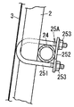
農業用設備1は、複数のフレーム2を備えており、複数のフレーム2がY軸方向に沿って所定の間隔で並べられている。複数のフレーム2同士は、第1連結フレーム23、及び一対の第2連結フレーム24で連結されている。第1連結フレーム23は、Y軸方向に沿って設けられており、複数のフレーム2各々の頂部20と機械的に結合されることで、複数のフレーム2同士を連結している。第2連結フレーム24は、Y軸方向に沿って設けられており、複数のフレーム2各々の支柱部21の上端部と機械的に結合されることで、複数のフレーム2同士を連結している。第2連結フレーム24は、フレーム2の内側に設けられている。第2連結フレーム24とフレーム2との結合には、例えば図2〜図4それぞれに示す結合部材25A,25B,25Cのいずれかが採用される。   The agricultural facility 1 includes a plurality of frames 2, and the plurality of frames 2 are arranged at predetermined intervals along the Y-axis direction. The plurality of frames 2 are connected by a first connection frame 23 and a pair of second connection frames 24. The first connection frame 23 is provided along the Y-axis direction, and is mechanically coupled to the top 20 of each of the plurality of frames 2 to connect the plurality of frames 2 to each other. The second connection frame 24 is provided along the Y-axis direction, and mechanically couples with the upper ends of the support columns 21 of the plurality of frames 2 to connect the plurality of frames 2 to each other. . The second connection frame 24 is provided inside the frame 2. For example, any one of the coupling members 25A, 25B, and 25C shown in FIGS. 2 to 4 is employed for coupling the second connection frame 24 and the frame 2.

図2に示す結合部材25Aは、いわゆるUボルトであり、U字状に形成された軸部251と、軸部251が通される一対の孔を有するプレート252と、軸部251に結合される一対のナット253とを備えている。結合部材25Aは、フレーム2と第2連結フレーム24とを、軸部251とプレート252とで挟み込むようにして結合する。   The coupling member 25A shown in FIG. 2 is a so-called U-bolt, and is coupled to the shaft portion 251 having a shaft portion 251 formed in a U shape, a plate 252 having a pair of holes through which the shaft portion 251 passes. And a pair of nuts 253. The coupling member 25 </ b> A couples the frame 2 and the second connection frame 24 so as to be sandwiched between the shaft portion 251 and the plate 252.

図3に示す結合部材25Bは、U字状に形成された板状の本体部254と、本体部254の開口を塞ぐ閉塞部255とを備えている。本体部254は、一対の対向壁256にU字状の切欠き257が形成されている。結合部材25Bは、対向壁256に沿うように本体部254に通されたフレーム2と、切欠き256に通された第2連結フレーム24とを交差させた状態で保持する。   The coupling member 25 </ b> B illustrated in FIG. 3 includes a plate-shaped main body 254 formed in a U shape and a closing portion 255 that closes the opening of the main body 254. The main body 254 has a U-shaped notch 257 formed in a pair of opposing walls 256. The coupling member 25 </ b> B holds the frame 2 passed through the main body 254 along the opposing wall 256 and the second connection frame 24 passed through the notch 256 in a crossed state.

図4に示す結合部材25Cは、なまし番線のような結束線(針金)であり、フレーム2と第2連結フレーム24とを束ねるようにして結合している。   The connecting member 25C shown in FIG. 4 is a binding wire (wire) such as an annealing wire, and connects the frame 2 and the second connection frame 24 so as to be bundled.

カーテン3は、例えば樹脂製のフィルム状部材(例えばポリオレフィンフィルム)、網状部材等で構成されており、透光率が例えば65〜75%程度の減光機能を有している。カーテン3は、巻上げ式のカーテン3であり、フレーム2の外側に設けられている。カーテン3は、Y軸方向における両端のフレーム2に跨るように配置されており、X軸方向の略中央部がフレーム2の頂部20に固定され、X軸方向の両端部(下端部30)それぞれが巻取軸31が取り付けられている。ここでいうカーテン3の下端部30とは、X軸方向におけるカーテン3の端部であり、巻取軸31に対して固定されている部分である。巻取軸31は、円柱状に形成されており、Y軸方向を軸方向とし、カーテン3を巻取可能に構成されている。   The curtain 3 is made of, for example, a resinous film-like member (for example, a polyolefin film), a mesh-like member, and the like, and has a light reduction function with a light transmittance of, for example, about 65 to 75%. The curtain 3 is a roll-up curtain 3 and is provided outside the frame 2. The curtain 3 is arranged so as to straddle the frames 2 at both ends in the Y-axis direction, the substantially central portion in the X-axis direction is fixed to the top portion 20 of the frame 2, and both end portions (lower end portions 30) in the X-axis direction. The take-up shaft 31 is attached. The lower end portion 30 of the curtain 3 here is an end portion of the curtain 3 in the X-axis direction and is a portion fixed to the winding shaft 31. The take-up shaft 31 is formed in a cylindrical shape, and is configured so that the curtain 3 can be taken up with the Y-axis direction as the axial direction.

フレーム2は、カーテン3が移動するときのガイドとしての機能を有しており、カーテン3の下端部30は、フレーム2に沿って移動する。具体的には、カーテン3は、巻取軸31に巻き取られることで下端部30がフレーム2に沿ってフレーム2の頂部20に向かって移動(上昇)する。また、カーテン3は、巻取軸31から繰り出されることで下端部30がフレーム2に沿って下向きに移動する。これにより、カーテン3が開閉し、フレーム2を覆う面積が増減して農業用設備1内に照射される光の量を調節することができる。   The frame 2 has a function as a guide when the curtain 3 moves, and the lower end portion 30 of the curtain 3 moves along the frame 2. Specifically, the curtain 3 is wound around the winding shaft 31 so that the lower end 30 moves (rises) along the frame 2 toward the top 20 of the frame 2. Further, the curtain 3 is drawn out from the take-up shaft 31 so that the lower end 30 moves downward along the frame 2. Thereby, the curtain 3 opens and closes, the area which covers the flame | frame 2 increases / decreases, and the quantity of the light irradiated in the agricultural equipment 1 can be adjusted.

なお、本実施形態のカーテン3は、1つの部材(フィルム)でフレーム2の頂部20からX軸方向の一方側を開閉する第1カーテン3aと、X軸方向の他方側を開閉する第2カーテン3bとを構成しているが、この構成に限らない。例えば、第1カーテン3aと第2カーテン3bとが別体に構成されていてもよい。また、カーテン3は、複数のフレーム2の全てに跨っている必要はなく、複数のフレーム2のうち少なくとも2本以上に跨って設けられていればよい。   The curtain 3 according to the present embodiment includes a first curtain 3a that opens and closes one side in the X-axis direction from the top portion 20 of the frame 2 and a second curtain that opens and closes the other side in the X-axis direction. Although 3b is comprised, it is not restricted to this structure. For example, the first curtain 3a and the second curtain 3b may be configured separately. Further, the curtain 3 does not have to extend over all of the plurality of frames 2, and may be provided over at least two of the plurality of frames 2.

巻取軸31は、軸方向の一端部に、巻取軸31を回転させる駆動装置4が設けられ、軸方向の他端部に、巻取軸31を水平に保つ振れ止め装置5が設けられている。   The winding shaft 31 is provided with a driving device 4 that rotates the winding shaft 31 at one end in the axial direction, and a steadying device 5 that keeps the winding shaft 31 horizontal at the other end in the axial direction. ing.

図5に駆動装置4の外観図を示す。駆動装置4は、モータ41、減速機42、及び駆動軸43を備えている。モータ41及び減速機42は、筐体44内に設けられている。モータ41は、外部電源からの電源供給によって出力軸を回転させる。減速機42は、モータ41の出力軸の回転数を所定の回転数に低減させて駆動軸43を回転させる。駆動軸43は、Y軸方向を軸方向とし、巻取軸31と機械的に結合されている。すなわち、駆動軸43は、巻取軸31と同軸となるように、巻取軸31に固定されている。駆動装置4は、モータ41の出力軸の回転方向に応じて駆動軸43を正転させることにより、巻取軸31にカーテン3を巻き取らせるように巻取軸31を回転させる。駆動装置4は、駆動軸43を逆転させることにより、巻取軸31からカーテン3を繰り出させるように巻取軸31を回転させる。また、駆動装置4は、減速機42があるため、モータ41の停止時に駆動軸43が回転しないように静止する。   FIG. 5 shows an external view of the driving device 4. The drive device 4 includes a motor 41, a speed reducer 42, and a drive shaft 43. The motor 41 and the speed reducer 42 are provided in the housing 44. The motor 41 rotates the output shaft by supplying power from an external power source. The reducer 42 rotates the drive shaft 43 by reducing the rotational speed of the output shaft of the motor 41 to a predetermined rotational speed. The drive shaft 43 is mechanically coupled to the winding shaft 31 with the Y-axis direction as the axial direction. That is, the drive shaft 43 is fixed to the winding shaft 31 so as to be coaxial with the winding shaft 31. The driving device 4 rotates the winding shaft 31 so that the winding shaft 31 winds up the curtain 3 by rotating the driving shaft 43 forward according to the rotation direction of the output shaft of the motor 41. The drive device 4 rotates the winding shaft 31 so that the curtain 3 is fed out from the winding shaft 31 by reversing the driving shaft 43. Further, since the drive device 4 has the speed reducer 42, the drive device 4 stops so that the drive shaft 43 does not rotate when the motor 41 is stopped.

駆動装置4は、第1滑車45、及び一対の第2滑車46を備えており、ガイドフレーム26に沿って移動自在に構成されている。図1に示すように、ガイドフレーム26は、フレーム2と同様の形状、すなわち逆U字状に形成されている。ガイドフレーム26は、複数のフレーム2が並ぶ構造物に対して、Y軸方向の一端側から離れて立てられている。また、ガイドフレーム26は、この構造物の一端であるフレーム2と、第1連結フレーム23、及び第3連結フレーム27により結合されている。   The drive device 4 includes a first pulley 45 and a pair of second pulleys 46, and is configured to be movable along the guide frame 26. As shown in FIG. 1, the guide frame 26 is formed in the same shape as the frame 2, that is, an inverted U shape. The guide frame 26 stands up away from one end side in the Y-axis direction with respect to the structure in which the plurality of frames 2 are arranged. The guide frame 26 is coupled to the frame 2 that is one end of the structure by the first connection frame 23 and the third connection frame 27.

第1滑車45、及び一対の第2滑車46は、筐体44に取り付けられている。第1滑車45と一対の第2滑車46とは、ガイドフレーム26を挟み込むように配置されている。第1滑車45は、駆動軸43と同軸となるように配置されており、ガイドフレーム26の外側に配置されている。一対の第2滑車46は、ガイドフレーム26の内側においてガイドフレーム26の軸方向に並ぶように配置されている。第1滑車45と一対の第2滑車46とは、駆動軸43とは別に自由に回転する。   The first pulley 45 and the pair of second pulleys 46 are attached to the housing 44. The first pulley 45 and the pair of second pulleys 46 are arranged so as to sandwich the guide frame 26. The first pulley 45 is disposed so as to be coaxial with the drive shaft 43 and is disposed outside the guide frame 26. The pair of second pulleys 46 are arranged inside the guide frame 26 so as to be aligned in the axial direction of the guide frame 26. The first pulley 45 and the pair of second pulleys 46 freely rotate separately from the drive shaft 43.

駆動装置4は、巻取軸31へのカーテン3の巻き取り、巻取軸31からのカーテン3の繰り出しに応じて、ガイドフレーム26に沿って移動する。具体的には、カーテン3は、その下端部30に設けられた巻取軸31、及び巻取軸31に設けられた駆動装置4等の重量により、フレーム2に沿って下向きに張られた状態となる。そして、巻取軸31がカーテン3を巻き取る向きに回転した場合、駆動装置4は、巻取軸31とともにガイドフレーム26に沿って上昇する。また、巻取軸31がカーテン3を繰り出す向きに回転した場合、駆動装置4は、自重によりガイドフレーム26に沿って下降する。なお、ガイドフレーム26とフレーム2とを結合する第3連結フレーム27は、第1滑車45、及び一対の第2滑車46と干渉しないように、駆動装置4の移動範囲における最下端位置の下側に配置されている。   The driving device 4 moves along the guide frame 26 in accordance with the winding of the curtain 3 around the winding shaft 31 and the feeding of the curtain 3 from the winding shaft 31. Specifically, the curtain 3 is stretched downward along the frame 2 due to the weight of the winding shaft 31 provided at the lower end 30 and the driving device 4 provided on the winding shaft 31. It becomes. When the winding shaft 31 rotates in the direction in which the curtain 3 is wound, the driving device 4 rises along the guide frame 26 together with the winding shaft 31. Further, when the winding shaft 31 rotates in the direction in which the curtain 3 is extended, the driving device 4 descends along the guide frame 26 by its own weight. The third connecting frame 27 that couples the guide frame 26 and the frame 2 is below the lowermost position in the moving range of the driving device 4 so as not to interfere with the first pulley 45 and the pair of second pulleys 46. Are arranged.

振れ止め装置5は、巻取軸31において駆動装置4とは反対側の端部に設けられている。振れ止め装置5は、錘51で構成されており、自重により巻取軸31に対して下向きの力を作用させる。すなわち、振れ止め装置5は、フレーム2に沿ってカーテン3を下に引っ張る向きの力を作用させる。   The steady rest device 5 is provided at the end of the winding shaft 31 on the side opposite to the drive device 4. The steady rest device 5 is composed of a weight 51 and applies a downward force to the winding shaft 31 by its own weight. That is, the steady rest device 5 applies a force in a direction of pulling the curtain 3 down along the frame 2.

側カーテン6は、Y軸方向における両端のフレーム2間にわたって設けられている。側カーテン6は、例えば樹脂製のフィルム状部材、網状部材等で構成されており、減光機能を有する。カーテン3は、主にフレーム2の連結部22を覆うのに対し、側カーテン6は、フレーム2の支柱部21を覆い、朝日や夕日等の高度が低い太陽から農業用設備1内に照射される光の量を調節する。また、側カーテン6は、農業用設備1内における風通しを制御する機能も有する。   The side curtain 6 is provided between the frames 2 at both ends in the Y-axis direction. The side curtain 6 is made of, for example, a resin film-like member, a net-like member, or the like, and has a light reduction function. The curtain 3 mainly covers the connecting portion 22 of the frame 2, while the side curtain 6 covers the column portion 21 of the frame 2, and is irradiated into the agricultural facility 1 from the sun with a low altitude such as the sun or sunset. Adjust the amount of light. The side curtain 6 also has a function of controlling ventilation in the agricultural facility 1.

側カーテン6は、上端部が支柱部21の上端部に固定されており、カーテン3の下端部30が最下端位置にある状態で、カーテン3の一部と重なるように配置されている(図1の第2カーテン3b参照)。また、側カーテン6の透光率は、カーテン3の透光率よりも低い。側カーテン6の下端部60には巻取軸61が取り付けられている。側カーテン6は、巻取軸61に巻き取られて下端部60がフレーム2の支柱部21に沿って上昇することで開けられ、巻取軸61から繰り出されて下端部60がフレーム2の支柱部21に沿って下降することで閉じられる。巻取軸61は、巻取軸31と同様に、Y軸方向の一端部に駆動装置4aが設けられ、Y軸方向の他端部に振れ止め装置5aが設けられている。なお、駆動装置4a、振れ止め装置5aそれぞれの構成は、駆動装置4、振れ止め装置5と同様の構成であるので説明を省略する。また、本実施形態では、駆動装置4と駆動装置4aとは、同一のガイドフレーム26に沿って移動するように構成されているが、互いに異なるガイドフレーム26に沿って移動するように構成されていてもよい。   The upper side of the side curtain 6 is fixed to the upper end of the support column 21, and the side curtain 6 is arranged so as to overlap a part of the curtain 3 with the lower end 30 of the curtain 3 being in the lowest end position (see FIG. 1 second curtain 3b). Further, the light transmittance of the side curtain 6 is lower than the light transmittance of the curtain 3. A winding shaft 61 is attached to the lower end portion 60 of the side curtain 6. The side curtain 6 is wound around the take-up shaft 61 and opened by raising the lower end portion 60 along the post portion 21 of the frame 2. The side curtain 6 is unwound from the take-up shaft 61 and the lower end portion 60 becomes the post of the frame 2. It is closed by descending along the part 21. As with the take-up shaft 31, the take-up shaft 61 is provided with a drive device 4a at one end in the Y-axis direction and with a steadying device 5a at the other end in the Y-axis direction. The configuration of each of the driving device 4a and the steadying device 5a is the same as that of the driving device 4 and the steadying device 5, and the description thereof will be omitted. In the present embodiment, the drive device 4 and the drive device 4a are configured to move along the same guide frame 26, but are configured to move along different guide frames 26. May be.

本実施形態において、水放出部7は、ミストの噴霧を行う噴霧装置71と、散水を行う散水装置73とを備えている。なお、水放出部7は、噴霧装置71と散水装置73との一方のみを備えた構成であってもよい。   In this embodiment, the water discharge | release part 7 is provided with the spraying apparatus 71 which sprays mist, and the watering apparatus 73 which sprays water. In addition, the structure provided with only one of the spraying apparatus 71 and the water sprinkling apparatus 73 may be sufficient as the water discharge | release part 7. FIG.

図6に噴霧装置71の概略構成図を示す。噴霧装置71は、配水部711とノズル712とを備えており、農業用設備1の内部空間に圃場の上方から霧状の水を放出する。すなわち、噴霧装置71は、ミストを散布する装置である。噴霧装置71は、ミストを散布することで、農業用設備1内の加湿、温度低下を図る。このミストの粒径は、10μm以上かつ100μm以下であることが望ましい。   FIG. 6 shows a schematic configuration diagram of the spraying device 71. The spraying device 71 includes a water distribution unit 711 and a nozzle 712, and discharges mist-like water into the internal space of the agricultural facility 1 from above the farm field. That is, the spray device 71 is a device that sprays mist. The spraying device 71 sprays mist so as to humidify and lower the temperature in the agricultural facility 1. The particle diameter of the mist is preferably 10 μm or more and 100 μm or less.

配水部711は、管状部材(例えばパイプ)を備える。配水部711は、複数のフレーム2間にわたりY軸方向に沿って設けられており、給水装置(例えば給水タンク、水道設備等)から供給された水が流れる。ノズル712は、配水部に取り付けられており、配水部711に流れる水をミストにして放出(噴霧)する。ノズル712は、配水部711においてY軸方向に所定間隔で複数設けられており、X−Y平面に沿った4方向にミストを放出する。   The water distribution unit 711 includes a tubular member (for example, a pipe). The water distribution unit 711 is provided along the Y-axis direction across the plurality of frames 2, and water supplied from a water supply device (for example, a water supply tank, a water supply facility, etc.) flows. The nozzle 712 is attached to the water distribution unit, and discharges (sprays) water flowing in the water distribution unit 711 as a mist. A plurality of nozzles 712 are provided at predetermined intervals in the Y-axis direction in the water distribution section 711, and discharge mist in four directions along the XY plane.

噴霧装置71は、取付部材72によりフレーム2の連結部22に取り付けられている。取付部材72は、例えば結束バンドであり、配水部711と連結部22とを束ねている。これにより、噴霧装置71は、複数のフレーム2間に架け渡されるようにして取り付けられている。本実施形態では、噴霧装置71は、X軸方向に離れた2つの直線状部分を有している。この直線状部分は、2つに限らず、1つあるいは3つ以上であってもよい。   The spray device 71 is attached to the connecting portion 22 of the frame 2 by an attachment member 72. The attachment member 72 is a binding band, for example, and bundles the water distribution part 711 and the connection part 22. Thus, the spray device 71 is attached so as to be bridged between the plurality of frames 2. In this embodiment, the spraying device 71 has two linear portions separated in the X-axis direction. The number of linear portions is not limited to two, but may be one or three or more.

図7に散水装置73の概略構成図を示す。散水装置73は、配水部731と散水部732とを備えており、農業用設備1内に散水する、具体的には圃場に潅水する装置である。   FIG. 7 shows a schematic configuration diagram of the watering device 73. The watering device 73 includes a water distribution unit 731 and a watering unit 732, and is a device that sprays water into the agricultural facility 1, specifically, waters the field.

配水部731は、管状部材(例えばパイプ、チューブ等)で構成されている。配水部731は、複数のフレーム2間にわたりY軸方向沿って設けられており、給水装置(例えば給水タンク、水道設備等)から供給された水が流れる。散水部732は、配水部731に形成された孔であり、Y軸方向に離れて複数形成されている。給水装置から配水部731に給水すると、配水部731に流れる水が散水部732から放出される。   The water distribution part 731 is configured by a tubular member (for example, a pipe, a tube, or the like). The water distribution part 731 is provided along the Y-axis direction across the plurality of frames 2, and water supplied from a water supply device (for example, a water supply tank, a water supply facility, etc.) flows. The water sprinkling part 732 is a hole formed in the water distribution part 731, and a plurality of water sprinkling parts 732 are formed apart in the Y-axis direction. When water is supplied from the water supply device to the water distribution unit 731, the water flowing through the water distribution unit 731 is discharged from the water sprinkling unit 732.

散水装置73は、取付部材74によりフレーム2の支柱部21に取り付けられている。取付部材74は、固定部741とアーム742と保持部743とを備えている。固定部741は、断面がC字状に形成されており、フレーム2の支柱部21を握るようにして支柱部21に固定されている。保持部743は、断面がC字状に形成されており、内側に通された配水部731を下から支えるように保持している。アーム742は、L字状に形成されており、一端が固定部741の胴体と結合し、他端が保持部743の胴体と結合している。本実施形態では、農業用設備1は、散水装置73を2つ備えており、一対の支柱部21それぞれに取り付けられている。   The watering device 73 is attached to the support column 21 of the frame 2 by an attachment member 74. The attachment member 74 includes a fixed portion 741, an arm 742, and a holding portion 743. The fixing portion 741 has a C-shaped cross section, and is fixed to the column portion 21 so as to grip the column portion 21 of the frame 2. The holding part 743 has a C-shaped cross section, and holds the water distribution part 731 passed through the inside from below. The arm 742 is formed in an L shape, and one end is coupled to the body of the fixing portion 741 and the other end is coupled to the body of the holding portion 743. In the present embodiment, the agricultural facility 1 includes two watering devices 73 and is attached to each of the pair of support columns 21.

次に、上記構成を備えた本実施形態の農業用設備1の効果について説明する。   Next, the effect of the agricultural equipment 1 of the present embodiment having the above configuration will be described.

本実施形態のカーテン3は、下端部30に巻取軸31が取り付けられた巻上げ式のカーテン3であり、巻取軸31の軸方向の一端側に巻取軸31を回転させる駆動装置4が設けられ、他端側に振れ止め装置5が設けられている。この振れ止め装置5による作用効果について、図8に示す比較例を用いて説明する。   The curtain 3 of the present embodiment is a winding curtain 3 in which a winding shaft 31 is attached to a lower end portion 30, and a driving device 4 that rotates the winding shaft 31 on one end side in the axial direction of the winding shaft 31 is provided. The steady rest device 5 is provided on the other end side. The effect by this steady rest apparatus 5 is demonstrated using the comparative example shown in FIG.

図8に示す比較例の農業用設備101は、巻取軸31に振れ止め装置5が設けられていない。巻取軸31は、一端側に設けられた駆動装置4によって回転させられるので、巻取軸31がカーテン3を巻き取る際に、巻取軸31がカーテン3に作用させる張力が巻取軸31の一端側と他端側とで異なる。巻取軸31は、巻取軸31の軸方向において、駆動装置4が設けられた巻取軸31の一端側がカーテン3に作用させる張力は、巻取軸31の他端側がカーテン3に作用させる張力よりも強い。言い換えれば、巻取軸31は、巻取軸31の軸方向において、駆動装置4と反対側がカーテン3に作用させる張力は弱い。したがって、巻取軸31において、駆動装置4とは反対側では、カーテン3が緩く巻き取られ、巻取軸31の1回転あたりのカーテン3の巻取り量が多くなるおそれがある。すなわち、巻取軸31の軸方向において、カーテン3の巻取り量が異なるために巻ずれが生じるおそれがある。これにより、図8に示すように、巻取軸31は、駆動装置4が設けられた一端側より、駆動装置4とは反対側の他端側が高くなるように傾斜し、カーテン3のスムーズな開閉が困難となるおそれがある。   In the agricultural equipment 101 of the comparative example shown in FIG. 8, the steadying device 5 is not provided on the winding shaft 31. Since the winding shaft 31 is rotated by the driving device 4 provided on one end side, when the winding shaft 31 winds up the curtain 3, the tension that the winding shaft 31 acts on the curtain 3 is increased. The one end side differs from the other end side. In the axial direction of the take-up shaft 31, the take-up shaft 31 has a tension applied to the curtain 3 by one end of the take-up shaft 31 provided with the driving device 4, and the other end of the take-up shaft 31 acts on the curtain 3. Stronger than tension. In other words, in the axial direction of the winding shaft 31, the winding shaft 31 has a weak tension that acts on the curtain 3 on the side opposite to the driving device 4. Therefore, on the winding shaft 31 on the side opposite to the driving device 4, the curtain 3 is loosely wound, and the winding amount of the curtain 3 per rotation of the winding shaft 31 may increase. That is, in the axial direction of the winding shaft 31, the winding amount of the curtain 3 is different, and thus there is a possibility that winding deviation occurs. Thereby, as shown in FIG. 8, the winding shaft 31 is inclined so that the other end side opposite to the driving device 4 is higher than the one end side where the driving device 4 is provided, and the curtain 3 is smooth. Opening and closing may be difficult.

一方、図9に示すように、本実施形態の農業用設備1は、巻取軸31の軸方向の一端側に駆動装置4が設けられ、他端側に振れ止め装置5として錘51が設けられている。この錘51の重量により、巻取軸31は、駆動装置4とは反対側においてカーテン3に作用させる張力が強くなる。したがって、巻取軸31の軸方向の一端側と他端側とにおいて、カーテン3に作用させる張力の差が低減し、巻取軸31が水平に保たれる。これにより、巻取軸31の軸方向において、カーテン3の巻取り量がほぼ等しくなり、カーテン3の巻ずれの発生が抑制され、カーテン3のスムーズな開閉を行うことが可能となる。   On the other hand, as shown in FIG. 9, the agricultural facility 1 of the present embodiment is provided with a drive device 4 on one end side in the axial direction of the take-up shaft 31 and a weight 51 as a steady rest device 5 on the other end side. It has been. Due to the weight of the weight 51, the winding shaft 31 has a strong tension acting on the curtain 3 on the side opposite to the driving device 4. Therefore, the difference in tension applied to the curtain 3 is reduced between the one end side and the other end side in the axial direction of the winding shaft 31, and the winding shaft 31 is kept horizontal. Thereby, in the axial direction of the winding shaft 31, the winding amount of the curtain 3 becomes substantially equal, the occurrence of winding deviation of the curtain 3 is suppressed, and the curtain 3 can be smoothly opened and closed.

また、カーテン3と同様に、側カーテン6についても、下端部60に取り付けられた巻取軸61に振れ止め装置5aが設けられているので、側カーテン6の開閉もスムーズに行うことが可能となる。   Similarly to the curtain 3, the side curtain 6 is provided with the steadying device 5 a on the winding shaft 61 attached to the lower end 60, so that the side curtain 6 can be opened and closed smoothly. Become.

また、本実施形態では、図2〜図4に示すように、複数のフレーム2同士を連結する第2連結フレーム24は、フレーム2の内側に設けられている。さらに、フレーム2と第2連結フレーム24とを結合する結合部材25A,25B,25Cは、フレーム2から外側方向への突出量が小さくなるように(例えば突出量が1cm以下)構成されている。これにより、カーテン3の下端部30の移動中にカーテン3が引っ掛かることなくフレーム2の外側に沿ってカーテン3の下端部30を移動させやすくなり、カーテン3をよりスムーズに開閉させることが可能となる。   In the present embodiment, as shown in FIGS. 2 to 4, the second connection frame 24 that connects the plurality of frames 2 is provided inside the frame 2. Furthermore, the coupling members 25A, 25B, and 25C that couple the frame 2 and the second connection frame 24 are configured so that the amount of protrusion from the frame 2 toward the outside is small (for example, the amount of protrusion is 1 cm or less). Thereby, it becomes easy to move the lower end part 30 of the curtain 3 along the outside of the frame 2 without the curtain 3 being caught while the lower end part 30 of the curtain 3 is moving, and the curtain 3 can be opened and closed more smoothly. Become.

また、本実施形態のカーテン3は、フレーム2の頂部20に固定され、下端部30が移動することで開閉するように構成されているが、この構成に限らない。例えば、カーテン3の下端部30がフレーム2に対して固定され、上端部がフレーム2に沿って移動することでカーテン3が開閉するように構成されていてもよい。   Moreover, although the curtain 3 of this embodiment is fixed to the top part 20 of the flame | frame 2, and it is comprised so that it may open and close by the lower end part 30 moving, it is not restricted to this structure. For example, the lower end 30 of the curtain 3 may be fixed with respect to the frame 2, and the curtain 3 may be configured to open and close when the upper end moves along the frame 2.

また、本実施形態では、巻取軸31の軸方向の一方側にのみ駆動装置4が設けられているが、巻取軸31の軸方向の両側に駆動装置4が設けられていてもよい。この場合、巻取軸31の軸方向の両側の駆動装置4で同期して巻取軸31を回転させることが好ましい。これにより、巻取軸31の軸方向において、巻取軸31がカーテン3に作用させる張力の差が低減され、巻ずれの発生が抑制されるので、カーテン3のスムーズな開閉を行うことができる。   In the present embodiment, the driving device 4 is provided only on one side of the winding shaft 31 in the axial direction. However, the driving device 4 may be provided on both sides of the winding shaft 31 in the axial direction. In this case, it is preferable to rotate the winding shaft 31 in synchronization with the drive devices 4 on both sides in the axial direction of the winding shaft 31. Thereby, in the axial direction of the winding shaft 31, the difference in tension that the winding shaft 31 acts on the curtain 3 is reduced and the occurrence of winding deviation is suppressed, so that the curtain 3 can be opened and closed smoothly. .

また、図10に示すように、本実施形態の農業用設備1は、ハウス本体8の内部に設けられている。本実施形態の農業用ハウス10は、農業用設備1と、農業用設備1の複数のフレーム2を、複数のフレーム2との間に隙間を空けて覆う被覆材8を有するハウス本体8とを備える。   As shown in FIG. 10, the agricultural facility 1 of the present embodiment is provided inside the house body 8. The agricultural house 10 of this embodiment includes an agricultural facility 1 and a house body 8 having a covering material 8 that covers the plurality of frames 2 of the agricultural facility 1 with a gap between the plurality of frames 2. Prepare.

ハウス本体8は、構造材としての機能を有する複数の外フレーム81と、複数の外フレーム81によって保持される被覆材82とを備えている。   The house body 8 includes a plurality of outer frames 81 having a function as a structural material and a covering material 82 held by the plurality of outer frames 81.

外フレーム81は、例えばアルミニウム等の金属パイプで構成されており、Y軸方向から見た外形が逆U字状に形成されている。外フレーム81は、農業用設備1のフレーム2よりも大きく形成されており、フレーム2から離れてフレーム2を覆うように配置されている。そして、複数の外フレーム81は、Y軸方向に沿って所定の間隔で並べて立てられている。なお、図10では、複数の外フレーム81のうち、Y軸方向の一端側及び他端側の外フレーム81のみ図示し、他の外フレーム81の図示を省略している。   The outer frame 81 is made of, for example, a metal pipe such as aluminum, and the outer shape viewed from the Y-axis direction is formed in an inverted U shape. The outer frame 81 is formed larger than the frame 2 of the agricultural facility 1 and is arranged so as to cover the frame 2 away from the frame 2. The plurality of outer frames 81 are erected side by side at predetermined intervals along the Y-axis direction. In FIG. 10, only the outer frame 81 on one end side and the other end side in the Y-axis direction among the plurality of outer frames 81 is illustrated, and illustration of the other outer frames 81 is omitted.

被覆材82は、例えば樹脂製のフィルム状部材(例えばポリオレフィンフィルム)等で構成されており、カーテン3、及び側カーテン6よりも高い透光性を有する。被覆材82は、複数の外フレーム81全体を覆うように設けられており、ハウス本体8の屋根821、側壁822、妻壁823として機能する。また、妻壁823には、出入口824が設けられている。   The covering material 82 is made of, for example, a resinous film-like member (for example, a polyolefin film) or the like, and has higher translucency than the curtain 3 and the side curtain 6. The covering material 82 is provided so as to cover the entire plurality of outer frames 81, and functions as the roof 821, the side wall 822, and the end wall 823 of the house body 8. The wife wall 823 is provided with an entrance / exit 824.

図11に示すように、本実施形態の農業用ハウス10は、複数の外フレーム81に保持された被覆材82が、農業用設備1と隙間を空けて農業用設備1を覆っている。これにより、被覆材82とカーテン3とが干渉することが抑制され、カーテン3をスムーズに開閉させることが可能となる。   As shown in FIG. 11, in the agricultural house 10 of the present embodiment, the covering material 82 held by a plurality of outer frames 81 covers the agricultural equipment 1 with a gap from the agricultural equipment 1. Thereby, interference with the covering material 82 and the curtain 3 is suppressed, and the curtain 3 can be opened and closed smoothly.

また、本実施形態の農業用設備1は、既存のハウス本体8内に設けることが可能である。したがって、既存のハウス本体8が、カーテン3、水放出部7等の取付けに対応していない構造であっても、本実施形態の農業用設備1を設けることで、カーテン3、水放出部7等を用いた植物の育成環境を形成することができる。   Moreover, the agricultural equipment 1 of this embodiment can be provided in the existing house body 8. Therefore, even if the existing house main body 8 has a structure that does not support attachment of the curtain 3, the water discharge portion 7 and the like, by providing the agricultural equipment 1 of the present embodiment, the curtain 3, the water discharge portion 7 It is possible to form a plant growth environment using the above.

なお、本実施形態の農業用ハウス10は、農業用設備1とハウス本体8とで構成されているが、ハウス本体8は必須の構成ではなく農業用設備1のみで構成されていてもよい。   In addition, although the agricultural house 10 of this embodiment is comprised with the agricultural equipment 1 and the house main body 8, the house main body 8 may be comprised only with the agricultural equipment 1 instead of an essential structure.

次に、農業用設備1の変形例について説明する。   Next, a modified example of the agricultural facility 1 will be described.

<第1変形例>
図12に、本変形例の農業用設備1Aの概略構成図を示す。本変形例の農業用設備1Aにおいて、カーテン3Aの下端部30の移動範囲における最下端位置は、フレーム2の連結部22の下端と地面との間の位置である。
<First Modification>
In FIG. 12, the schematic block diagram of the agricultural equipment 1A of this modification is shown. In the agricultural facility 1A of the present modification, the lowermost position in the movement range of the lower end 30 of the curtain 3A is a position between the lower end of the connecting portion 22 of the frame 2 and the ground.

本変形例の農業用設備1Aは、側カーテン6を備えておらず、カーテン3Aが側カーテン6の機能を兼ねている。本変形例のカーテン3Aは、下端部30の移動範囲における最下端位置は、地面近くに設定されており、フレーム2の支柱部21も覆うことが可能に構成されている。これにより、側カーテン6を省略することができるので、農業用設備1Aの構成を簡略化することができる。   The agricultural facility 1 </ b> A of this modification does not include the side curtain 6, and the curtain 3 </ b> A also functions as the side curtain 6. The curtain 3A according to the present modification is configured such that the lowermost position in the movement range of the lower end 30 is set near the ground, and can also cover the support column 21 of the frame 2. Thereby, since the side curtain 6 can be abbreviate | omitted, the structure of the agricultural equipment 1A can be simplified.

<第2変形例>
図13A、図13Bに本変形例の農業用設備1の概略構成図を示す。本変形例の農業用設備1において、振れ止め装置5は、巻取軸31に巻取可能な帯状部材52である。帯状部材52は、上端部53が巻取軸31に取り付けられ、下端部54が巻取軸31よりも下側においてフレーム2に対して固定されている。
<Second Modification>
The schematic block diagram of the agricultural equipment 1 of this modification is shown to FIG. 13A and FIG. 13B. In the agricultural facility 1 of this modification, the steady rest device 5 is a belt-like member 52 that can be wound around the winding shaft 31. The belt-like member 52 has an upper end portion 53 attached to the winding shaft 31 and a lower end portion 54 fixed to the frame 2 below the winding shaft 31.

本実施形態の帯状部材52は、カーテン3と同様に樹脂製のフィルム状部材(例えばポリオレフィンフィルム)、網状部材等で構成されており、巻取軸31に対して駆動装置4とは反対側の端部に設けられている。帯状部材52は、Y軸方向を幅方向とし、上端部53が巻取軸31に取り付けられ、下端部54が固定軸55に取り付けられている。固定軸55は、Y軸方向を軸方向として、複数のフレーム2の支柱部21に固定されている。また、帯状部材52は、フレーム2に沿って張られた状態となるように、巻取軸31に対してカーテン3とは反対向きに巻き取られている。すなわち、巻取軸31がカーテン3を巻き取る向きに回転した場合、帯状部材52は巻取軸31から繰り出され、巻取軸31がカーテン3を繰り出す向きに回転した場合、帯状部材52は巻取軸31に巻き取られる。   The belt-like member 52 of the present embodiment is formed of a resin film-like member (for example, a polyolefin film), a net-like member, etc., similar to the curtain 3, and is opposite to the drive device 4 with respect to the winding shaft 31. It is provided at the end. The belt-like member 52 has the Y-axis direction as the width direction, the upper end portion 53 is attached to the take-up shaft 31, and the lower end portion 54 is attached to the fixed shaft 55. The fixed shaft 55 is fixed to the column portions 21 of the plurality of frames 2 with the Y-axis direction as the axial direction. Further, the belt-like member 52 is wound around the winding shaft 31 in the direction opposite to the curtain 3 so as to be stretched along the frame 2. That is, when the winding shaft 31 rotates in the direction to wind up the curtain 3, the belt-like member 52 is fed out from the winding shaft 31, and when the winding shaft 31 rotates in the direction of feeding out the curtain 3, the belt-like member 52 is wound up. It is wound around the take-up shaft 31.

上記構成により、巻取軸31がカーテン3を巻き取る際に、巻取軸31における駆動装置4とは反対側の端部が、駆動装置4側の端部よりも高くならないように帯状部材52により規制され、巻取軸31が水平に保たれる。これにより、巻取軸31の軸方向において、カーテン3の巻取り量がほぼ等しくなり、カーテン3の巻ずれの発生が抑制され、カーテン3のスムーズな開閉を行うことが可能となる。   With the above configuration, when the winding shaft 31 winds up the curtain 3, the end of the winding shaft 31 on the side opposite to the driving device 4 is not higher than the end on the driving device 4 side. The winding shaft 31 is kept horizontal. Thereby, in the axial direction of the winding shaft 31, the winding amount of the curtain 3 becomes substantially equal, the occurrence of winding deviation of the curtain 3 is suppressed, and the curtain 3 can be smoothly opened and closed.

なお、上述した実施形態は本発明の一例である。このため、本発明は、上述の実施形態に限定されることはなく、この実施形態以外であっても、本発明に係る技術的思想を逸脱しない範囲であれば、設計等に応じて種々の変更が可能であることはもちろんのことである。   The above-described embodiment is an example of the present invention. For this reason, the present invention is not limited to the above-described embodiment, and various modifications can be made according to design and the like as long as the technical idea according to the present invention is not deviated from this embodiment. Of course, it can be changed.

1 農業用設備
10 農業用ハウス
2 フレーム
21 支柱部
22 連結部
3 カーテン
30 下端部
31 巻取軸
4 駆動装置
5 振れ止め装置
51 錘
52 帯状部材
53 上端部
54 下端部
6 側カーテン
60 下端部
7 水放出部
71 噴霧装置
73 散水装置
8 ハウス本体
82 被覆材
DESCRIPTION OF SYMBOLS 1 Agricultural equipment 10 Agricultural house 2 Frame 21 Strut part 22 Connecting part 3 Curtain 30 Lower end part 31 Winding shaft 4 Driving device 5 Stabilizing device 51 Weight 52 Strip member 53 Upper end part 54 Lower end part 6 Side curtain 60 Lower end part 7 Water discharge part 71 Spraying device 73 Sprinkling device 8 House body 82 Covering material

Claims (10)

一対の支柱部、及び前記一対の支柱部の上端同士を連結する連結部を有する逆U字状に形成された複数のフレームと、
前記フレームが囲む面と交差する方向に離れて立てられる前記複数のフレームの外側に配置され、下端部が前記複数のフレームに沿って移動するカーテンと、
前記カーテンの前記下端部に取り付けられる巻取軸を回転させる駆動装置と、
前記巻取軸を水平に保つ振れ止め装置とを備える
ことを特徴とする農業用設備。
A plurality of frames formed in an inverted U shape having a pair of struts and a connecting part that connects the upper ends of the pair of struts;
A curtain that is arranged outside the plurality of frames that are set apart in a direction intersecting a surface that the frame surrounds, and a lower end portion of which moves along the plurality of frames;
A driving device for rotating a winding shaft attached to the lower end of the curtain;
Agricultural equipment, comprising: a steady rest that keeps the winding shaft horizontal.
前記駆動装置は、前記巻取軸の軸方向の一端側に設けられ、
前記振れ止め装置は、前記巻取軸の軸方向の他端側に設けられる
ことを特徴とする請求項1に記載の農業用設備。
The driving device is provided on one end side in the axial direction of the winding shaft,
The agricultural equipment according to claim 1, wherein the steady rest device is provided on the other end side in the axial direction of the winding shaft.
前記振れ止め装置は、錘である
ことを特徴とする請求項2に記載の農業用設備。
The agricultural equipment according to claim 2, wherein the steady rest is a weight.
前記振れ止め装置は、前記巻取軸に巻取可能な帯状部材であり、
前記帯状部材は、上端部が、前記巻取軸に取り付けられ、下端部が、前記巻取軸よりも下側において前記フレームに対して固定されている
ことを特徴とする請求項2に記載の農業用設備。
The steady rest device is a belt-like member that can be wound around the winding shaft,
The upper end portion of the band-shaped member is attached to the take-up shaft, and the lower end portion is fixed to the frame at a lower side than the take-up shaft. Agricultural equipment.
前記カーテンの前記下端部の移動範囲における最下端位置は、前記連結部の下端と地面との間の位置である
ことを特徴とする請求項1〜4のいずれか1項に記載の農業用設備。
The agricultural equipment according to any one of claims 1 to 4, wherein the lowermost position in the movement range of the lower end part of the curtain is a position between the lower end of the connecting part and the ground. .
前記支柱部に沿って下端部が移動する側カーテンをさらに備える
ことを特徴とする請求項1〜5のいずれか1項に記載の農業用設備。
The agricultural facility according to any one of claims 1 to 5, further comprising a side curtain whose lower end moves along the support column.
前記フレームに取り付けられ、水を放出する水放出部をさらに備える
ことを特徴とする請求項1〜6のいずれか1項に記載の農業用設備。
The agricultural facility according to any one of claims 1 to 6, further comprising a water discharge portion that is attached to the frame and discharges water.
前記水放出部は、噴霧を行う噴霧装置を含む
ことを特徴とする請求項7に記載の農業用設備。
The agricultural facility according to claim 7, wherein the water discharge unit includes a spraying device that performs spraying.
前記水放出部は、散水を行う散水装置を含む
ことを特徴とする請求項7又は8に記載の農業用設備。
The agricultural facility according to claim 7 or 8, wherein the water discharge unit includes a watering device that performs watering.
請求項1〜9のいずれか1項に記載の農業用設備と、
前記農業用設備の前記複数のフレームを、前記複数のフレームとの間に隙間を空けて覆う被覆材を有するハウス本体とを備える
ことを特徴とする農業用ハウス。
Agricultural equipment according to any one of claims 1 to 9,
An agricultural house, comprising: a house body having a covering material that covers the plurality of frames of the agricultural facility with a gap between the plurality of frames.
JP2015241434A 2015-12-10 2015-12-10 Agricultural equipment and agricultural house using the same Active JP6741981B2 (en)

Priority Applications (1)

Application Number Priority Date Filing Date Title
JP2015241434A JP6741981B2 (en) 2015-12-10 2015-12-10 Agricultural equipment and agricultural house using the same

Applications Claiming Priority (1)

Application Number Priority Date Filing Date Title
JP2015241434A JP6741981B2 (en) 2015-12-10 2015-12-10 Agricultural equipment and agricultural house using the same

Publications (2)

Publication Number Publication Date
JP2017104062A true JP2017104062A (en) 2017-06-15
JP6741981B2 JP6741981B2 (en) 2020-08-19

Family

ID=59058137

Family Applications (1)

Application Number Title Priority Date Filing Date
JP2015241434A Active JP6741981B2 (en) 2015-12-10 2015-12-10 Agricultural equipment and agricultural house using the same

Country Status (1)

Country Link
JP (1) JP6741981B2 (en)

Cited By (1)

* Cited by examiner, † Cited by third party
Publication number Priority date Publication date Assignee Title
JP2019017324A (en) * 2017-07-19 2019-02-07 国立研究開発法人農業・食品産業技術総合研究機構 Opening/closing apparatus of covering material

Citations (7)

* Cited by examiner, † Cited by third party
Publication number Priority date Publication date Assignee Title
JPS5214020U (en) * 1975-07-17 1977-02-01
JPS58117436U (en) * 1982-02-05 1983-08-10 誠和化学株式会社 Winding device for film, etc.
JPS6137767U (en) * 1984-08-10 1986-03-08 株式会社 田窪工業所 greenhouse curtain equipment
JPH06217651A (en) * 1992-08-03 1994-08-09 Fumihide Matsuda Apparatus for winding and unwinding shading sheet of greenhouse or the like
JP2014057570A (en) * 2012-08-23 2014-04-03 Panasonic Corp Agricultural greenhouse
US20140157662A1 (en) * 2012-11-14 2014-06-12 David Wallace Automated canopy greenhouse
JP2015142545A (en) * 2013-12-25 2015-08-06 パナソニックIpマネジメント株式会社 Agricultural greenhouse, and opening/closing apparatus

Patent Citations (7)

* Cited by examiner, † Cited by third party
Publication number Priority date Publication date Assignee Title
JPS5214020U (en) * 1975-07-17 1977-02-01
JPS58117436U (en) * 1982-02-05 1983-08-10 誠和化学株式会社 Winding device for film, etc.
JPS6137767U (en) * 1984-08-10 1986-03-08 株式会社 田窪工業所 greenhouse curtain equipment
JPH06217651A (en) * 1992-08-03 1994-08-09 Fumihide Matsuda Apparatus for winding and unwinding shading sheet of greenhouse or the like
JP2014057570A (en) * 2012-08-23 2014-04-03 Panasonic Corp Agricultural greenhouse
US20140157662A1 (en) * 2012-11-14 2014-06-12 David Wallace Automated canopy greenhouse
JP2015142545A (en) * 2013-12-25 2015-08-06 パナソニックIpマネジメント株式会社 Agricultural greenhouse, and opening/closing apparatus

Cited By (2)

* Cited by examiner, † Cited by third party
Publication number Priority date Publication date Assignee Title
JP2019017324A (en) * 2017-07-19 2019-02-07 国立研究開発法人農業・食品産業技術総合研究機構 Opening/closing apparatus of covering material
JP6993668B2 (en) 2017-07-19 2022-01-13 国立研究開発法人農業・食品産業技術総合研究機構 Switchgear for covering materials

Also Published As

Publication number Publication date
JP6741981B2 (en) 2020-08-19

Similar Documents

Publication Publication Date Title
US1106624A (en) Protective covering for orchards.
US20150164004A1 (en) Agricultural house
JP2013063061A (en) Ventilating system of cultivation greenhouse facility
JP2017104062A (en) Agricultural equipment and agricultural house using the same
WO2015087481A1 (en) Greenhouse for agricultural use and opening and closing device
CN205222306U (en) Vehicular water pipe receiving mechanism of telecontrolled aircraft direction
CN208940510U (en) A kind of agricultural planting greenhouse with sunshading and heat-insulating cover
WO2012157588A1 (en) Pollination apparatus and pollination device
JP4234148B2 (en) Units used for construction of agricultural and horticultural houses
CN211297860U (en) Greenhouse spraying device
US2024374A (en) Overhead irrigation system
JP6861371B2 (en) Agricultural house, curtain system of agricultural house
CN105875281A (en) Photovoltaic ecological house with closable side part
CN216753071U (en) Special drip irrigation system of flowers in air
CN206274888U (en) A kind of agricultural planting greenhouse
CN110679349A (en) Automatic climing device that falls in greenhouse
ES2899283T3 (en) Apparatus and system for the transfer of suspended objects
KR101830570B1 (en) Foldable awning apparatus for wide area
CN210382073U (en) Quick tectorial membrane frock of green vegetables selective breeding with planting canopy
CN110544447B (en) Make things convenient for banner fixed equipment of dismouting
KR101830556B1 (en) Auto foldable vertical awning apparatus
KR101369837B1 (en) The vinyl house that can easily shield the light
CN206061949U (en) A kind of accurate sprinkling system of crops
CN205682023U (en) Glasshouse
CN205378624U (en) Big -arch shelter machine that leaks informaton

Legal Events

Date Code Title Description
RD02 Notification of acceptance of power of attorney

Free format text: JAPANESE INTERMEDIATE CODE: A7422

Effective date: 20170127

A621 Written request for application examination

Free format text: JAPANESE INTERMEDIATE CODE: A621

Effective date: 20181025

A131 Notification of reasons for refusal

Free format text: JAPANESE INTERMEDIATE CODE: A131

Effective date: 20190611

A977 Report on retrieval

Free format text: JAPANESE INTERMEDIATE CODE: A971007

Effective date: 20190614

A521 Request for written amendment filed

Free format text: JAPANESE INTERMEDIATE CODE: A523

Effective date: 20190813

A02 Decision of refusal

Free format text: JAPANESE INTERMEDIATE CODE: A02

Effective date: 20200107

A521 Request for written amendment filed

Free format text: JAPANESE INTERMEDIATE CODE: A523

Effective date: 20200406

A911 Transfer to examiner for re-examination before appeal (zenchi)

Free format text: JAPANESE INTERMEDIATE CODE: A911

Effective date: 20200416

TRDD Decision of grant or rejection written
A01 Written decision to grant a patent or to grant a registration (utility model)

Free format text: JAPANESE INTERMEDIATE CODE: A01

Effective date: 20200616

A61 First payment of annual fees (during grant procedure)

Free format text: JAPANESE INTERMEDIATE CODE: A61

Effective date: 20200710

R151 Written notification of patent or utility model registration

Ref document number: 6741981

Country of ref document: JP

Free format text: JAPANESE INTERMEDIATE CODE: R151