JP2017102480A - Color display device - Google Patents
Color display device Download PDFInfo
- Publication number
- JP2017102480A JP2017102480A JP2017033207A JP2017033207A JP2017102480A JP 2017102480 A JP2017102480 A JP 2017102480A JP 2017033207 A JP2017033207 A JP 2017033207A JP 2017033207 A JP2017033207 A JP 2017033207A JP 2017102480 A JP2017102480 A JP 2017102480A
- Authority
- JP
- Japan
- Prior art keywords
- type
- pigment particles
- particles
- color
- white
- Prior art date
- Legal status (The legal status is an assumption and is not a legal conclusion. Google has not performed a legal analysis and makes no representation as to the accuracy of the status listed.)
- Granted
Links
- 239000002245 particle Substances 0.000 claims abstract description 376
- 239000000049 pigment Substances 0.000 claims abstract description 194
- 239000012530 fluid Substances 0.000 claims abstract description 48
- 239000002904 solvent Substances 0.000 claims abstract description 12
- 239000011877 solvent mixture Substances 0.000 claims abstract description 8
- 238000000034 method Methods 0.000 claims description 41
- 239000003086 colorant Substances 0.000 claims description 6
- 239000000654 additive Substances 0.000 claims description 5
- 230000000996 additive effect Effects 0.000 claims description 4
- 239000003094 microcapsule Substances 0.000 claims description 4
- 230000003993 interaction Effects 0.000 claims description 3
- 230000000007 visual effect Effects 0.000 description 7
- 238000012986 modification Methods 0.000 description 6
- 230000004048 modification Effects 0.000 description 6
- NNBZCPXTIHJBJL-UHFFFAOYSA-N decalin Chemical compound C1CCCC2CCCCC21 NNBZCPXTIHJBJL-UHFFFAOYSA-N 0.000 description 4
- 239000012463 white pigment Substances 0.000 description 4
- 241000720945 Hosta Species 0.000 description 3
- YXFVVABEGXRONW-UHFFFAOYSA-N Toluene Chemical compound CC1=CC=CC=C1 YXFVVABEGXRONW-UHFFFAOYSA-N 0.000 description 3
- 239000003795 chemical substances by application Substances 0.000 description 3
- -1 isopar Chemical class 0.000 description 3
- 239000000463 material Substances 0.000 description 3
- 239000000203 mixture Substances 0.000 description 3
- 230000003287 optical effect Effects 0.000 description 3
- 238000013459 approach Methods 0.000 description 2
- 238000013461 design Methods 0.000 description 2
- 238000005516 engineering process Methods 0.000 description 2
- 150000008282 halocarbons Chemical class 0.000 description 2
- 229910052736 halogen Inorganic materials 0.000 description 2
- 150000002367 halogens Chemical class 0.000 description 2
- PGFXOWRDDHCDTE-UHFFFAOYSA-N hexafluoropropylene oxide Chemical compound FC(F)(F)C1(F)OC1(F)F PGFXOWRDDHCDTE-UHFFFAOYSA-N 0.000 description 2
- 239000003921 oil Substances 0.000 description 2
- 229920000642 polymer Polymers 0.000 description 2
- 238000000926 separation method Methods 0.000 description 2
- 229910052596 spinel Inorganic materials 0.000 description 2
- 239000011029 spinel Substances 0.000 description 2
- OJOWICOBYCXEKR-APPZFPTMSA-N (1S,4R)-5-ethylidenebicyclo[2.2.1]hept-2-ene Chemical compound CC=C1C[C@@H]2C[C@@H]1C=C2 OJOWICOBYCXEKR-APPZFPTMSA-N 0.000 description 1
- FBTKIMWGAQACHU-UHFFFAOYSA-N 1,1-dichlorononane Chemical compound CCCCCCCCC(Cl)Cl FBTKIMWGAQACHU-UHFFFAOYSA-N 0.000 description 1
- USPWUOFNOTUBAD-UHFFFAOYSA-N 1,2,3,4,5-pentafluoro-6-(trifluoromethyl)benzene Chemical compound FC1=C(F)C(F)=C(C(F)(F)F)C(F)=C1F USPWUOFNOTUBAD-UHFFFAOYSA-N 0.000 description 1
- UWTFGHPTJQPZQP-UHFFFAOYSA-N 1,2,3,4-tetrafluoro-5,6-bis(trifluoromethyl)benzene Chemical group FC1=C(F)C(F)=C(C(F)(F)F)C(C(F)(F)F)=C1F UWTFGHPTJQPZQP-UHFFFAOYSA-N 0.000 description 1
- FBKFIAIRSQOXJR-UHFFFAOYSA-N 1,2,3-trichloro-5-(trifluoromethyl)benzene Chemical compound FC(F)(F)C1=CC(Cl)=C(Cl)C(Cl)=C1 FBKFIAIRSQOXJR-UHFFFAOYSA-N 0.000 description 1
- BJYHBJUWZMHGGQ-UHFFFAOYSA-N 1,2-dichloro-3-(trifluoromethyl)benzene Chemical compound FC(F)(F)C1=CC=CC(Cl)=C1Cl BJYHBJUWZMHGGQ-UHFFFAOYSA-N 0.000 description 1
- GNPWYHFXSMINJQ-UHFFFAOYSA-N 1,2-dimethyl-3-(1-phenylethyl)benzene Chemical compound C=1C=CC(C)=C(C)C=1C(C)C1=CC=CC=C1 GNPWYHFXSMINJQ-UHFFFAOYSA-N 0.000 description 1
- KGCDGLXSBHJAHZ-UHFFFAOYSA-N 1-chloro-2,3,4,5,6-pentafluorobenzene Chemical compound FC1=C(F)C(F)=C(Cl)C(F)=C1F KGCDGLXSBHJAHZ-UHFFFAOYSA-N 0.000 description 1
- IAFBRPFISOTXSO-UHFFFAOYSA-N 2-[[2-chloro-4-[3-chloro-4-[[1-(2,4-dimethylanilino)-1,3-dioxobutan-2-yl]diazenyl]phenyl]phenyl]diazenyl]-n-(2,4-dimethylphenyl)-3-oxobutanamide Chemical compound C=1C=C(C)C=C(C)C=1NC(=O)C(C(=O)C)N=NC(C(=C1)Cl)=CC=C1C(C=C1Cl)=CC=C1N=NC(C(C)=O)C(=O)NC1=CC=C(C)C=C1C IAFBRPFISOTXSO-UHFFFAOYSA-N 0.000 description 1
- LQZFGPJGXVFSTR-UHFFFAOYSA-N 2-[[2-chloro-4-[3-chloro-4-[[1-(2-methylanilino)-1,3-dioxobutan-2-yl]diazenyl]phenyl]phenyl]diazenyl]-n-(2-methylphenyl)-3-oxobutanamide Chemical compound C=1C=CC=C(C)C=1NC(=O)C(C(=O)C)N=NC(C(=C1)Cl)=CC=C1C(C=C1Cl)=CC=C1N=NC(C(C)=O)C(=O)NC1=CC=CC=C1C LQZFGPJGXVFSTR-UHFFFAOYSA-N 0.000 description 1
- 229910018072 Al 2 O 3 Inorganic materials 0.000 description 1
- PWHULOQIROXLJO-UHFFFAOYSA-N Manganese Chemical compound [Mn] PWHULOQIROXLJO-UHFFFAOYSA-N 0.000 description 1
- CTQNGGLPUBDAKN-UHFFFAOYSA-N O-Xylene Chemical compound CC1=CC=CC=C1C CTQNGGLPUBDAKN-UHFFFAOYSA-N 0.000 description 1
- 239000005662 Paraffin oil Substances 0.000 description 1
- NRCMAYZCPIVABH-UHFFFAOYSA-N Quinacridone Chemical compound N1C2=CC=CC=C2C(=O)C2=C1C=C1C(=O)C3=CC=CC=C3NC1=C2 NRCMAYZCPIVABH-UHFFFAOYSA-N 0.000 description 1
- 229910010413 TiO 2 Inorganic materials 0.000 description 1
- WLDHEUZGFKACJH-UHFFFAOYSA-K amaranth Chemical compound [Na+].[Na+].[Na+].C12=CC=C(S([O-])(=O)=O)C=C2C=C(S([O-])(=O)=O)C(O)=C1N=NC1=CC=C(S([O-])(=O)=O)C2=CC=CC=C12 WLDHEUZGFKACJH-UHFFFAOYSA-K 0.000 description 1
- 150000004945 aromatic hydrocarbons Chemical class 0.000 description 1
- 239000006229 carbon black Substances 0.000 description 1
- LEYJJTBJCFGAQN-UHFFFAOYSA-N chembl1985378 Chemical compound OC1=CC=C2C=CC=CC2=C1N=NC(C=C1)=CC=C1N=NC1=CC=C(S(O)(=O)=O)C=C1 LEYJJTBJCFGAQN-UHFFFAOYSA-N 0.000 description 1
- UUAGAQFQZIEFAH-UHFFFAOYSA-N chlorotrifluoroethylene Chemical group FC(F)=C(F)Cl UUAGAQFQZIEFAH-UHFFFAOYSA-N 0.000 description 1
- 235000009508 confectionery Nutrition 0.000 description 1
- JGDFBJMWFLXCLJ-UHFFFAOYSA-N copper chromite Chemical compound [Cu]=O.[Cu]=O.O=[Cr]O[Cr]=O JGDFBJMWFLXCLJ-UHFFFAOYSA-N 0.000 description 1
- XCJYREBRNVKWGJ-UHFFFAOYSA-N copper(II) phthalocyanine Chemical compound [Cu+2].C12=CC=CC=C2C(N=C2[N-]C(C3=CC=CC=C32)=N2)=NC1=NC([C]1C=CC=CC1=1)=NC=1N=C1[C]3C=CC=CC3=C2[N-]1 XCJYREBRNVKWGJ-UHFFFAOYSA-N 0.000 description 1
- 239000004205 dimethyl polysiloxane Substances 0.000 description 1
- KWKXNDCHNDYVRT-UHFFFAOYSA-N dodecylbenzene Chemical compound CCCCCCCCCCCCC1=CC=CC=C1 KWKXNDCHNDYVRT-UHFFFAOYSA-N 0.000 description 1
- 239000000975 dye Substances 0.000 description 1
- 238000002296 dynamic light scattering Methods 0.000 description 1
- 239000003792 electrolyte Substances 0.000 description 1
- 239000010685 fatty oil Substances 0.000 description 1
- 239000004519 grease Substances 0.000 description 1
- 229930195733 hydrocarbon Natural products 0.000 description 1
- 150000002430 hydrocarbons Chemical class 0.000 description 1
- 239000001023 inorganic pigment Substances 0.000 description 1
- 229910052748 manganese Inorganic materials 0.000 description 1
- 239000011572 manganese Substances 0.000 description 1
- 239000011159 matrix material Substances 0.000 description 1
- 239000012860 organic pigment Substances 0.000 description 1
- 239000011236 particulate material Substances 0.000 description 1
- CEOCDNVZRAIOQZ-UHFFFAOYSA-N pentachlorobenzene Chemical compound ClC1=CC(Cl)=C(Cl)C(Cl)=C1Cl CEOCDNVZRAIOQZ-UHFFFAOYSA-N 0.000 description 1
- 229950011087 perflunafene Drugs 0.000 description 1
- UWEYRJFJVCLAGH-IJWZVTFUSA-N perfluorodecalin Chemical compound FC1(F)C(F)(F)C(F)(F)C(F)(F)[C@@]2(F)C(F)(F)C(F)(F)C(F)(F)C(F)(F)[C@@]21F UWEYRJFJVCLAGH-IJWZVTFUSA-N 0.000 description 1
- 239000010701 perfluoropolyalkylether Substances 0.000 description 1
- IEQIEDJGQAUEQZ-UHFFFAOYSA-N phthalocyanine Chemical compound N1C(N=C2C3=CC=CC=C3C(N=C3C4=CC=CC=C4C(=N4)N3)=N2)=C(C=CC=C2)C2=C1N=C1C2=CC=CC=C2C4=N1 IEQIEDJGQAUEQZ-UHFFFAOYSA-N 0.000 description 1
- 229920000435 poly(dimethylsiloxane) Polymers 0.000 description 1
- 229920000867 polyelectrolyte Polymers 0.000 description 1
- 229920001296 polysiloxane Polymers 0.000 description 1
- 238000002310 reflectometry Methods 0.000 description 1
- 229920006395 saturated elastomer Polymers 0.000 description 1
- 229920002545 silicone oil Polymers 0.000 description 1
- 239000000126 substance Substances 0.000 description 1
- 239000000758 substrate Substances 0.000 description 1
- 239000004094 surface-active agent Substances 0.000 description 1
- 238000012360 testing method Methods 0.000 description 1
- 239000010409 thin film Substances 0.000 description 1
- PXXNTAGJWPJAGM-UHFFFAOYSA-N vertaline Natural products C1C2C=3C=C(OC)C(OC)=CC=3OC(C=C3)=CC=C3CCC(=O)OC1CC1N2CCCC1 PXXNTAGJWPJAGM-UHFFFAOYSA-N 0.000 description 1
- 239000008096 xylene Substances 0.000 description 1
- 229910000859 α-Fe Inorganic materials 0.000 description 1
Images


Classifications
-
- G—PHYSICS
- G02—OPTICS
- G02F—OPTICAL DEVICES OR ARRANGEMENTS FOR THE CONTROL OF LIGHT BY MODIFICATION OF THE OPTICAL PROPERTIES OF THE MEDIA OF THE ELEMENTS INVOLVED THEREIN; NON-LINEAR OPTICS; FREQUENCY-CHANGING OF LIGHT; OPTICAL LOGIC ELEMENTS; OPTICAL ANALOGUE/DIGITAL CONVERTERS
- G02F1/00—Devices or arrangements for the control of the intensity, colour, phase, polarisation or direction of light arriving from an independent light source, e.g. switching, gating or modulating; Non-linear optics
- G02F1/01—Devices or arrangements for the control of the intensity, colour, phase, polarisation or direction of light arriving from an independent light source, e.g. switching, gating or modulating; Non-linear optics for the control of the intensity, phase, polarisation or colour
- G02F1/165—Devices or arrangements for the control of the intensity, colour, phase, polarisation or direction of light arriving from an independent light source, e.g. switching, gating or modulating; Non-linear optics for the control of the intensity, phase, polarisation or colour based on translational movement of particles in a fluid under the influence of an applied field
- G02F1/166—Devices or arrangements for the control of the intensity, colour, phase, polarisation or direction of light arriving from an independent light source, e.g. switching, gating or modulating; Non-linear optics for the control of the intensity, phase, polarisation or colour based on translational movement of particles in a fluid under the influence of an applied field characterised by the electro-optical or magneto-optical effect
- G02F1/167—Devices or arrangements for the control of the intensity, colour, phase, polarisation or direction of light arriving from an independent light source, e.g. switching, gating or modulating; Non-linear optics for the control of the intensity, phase, polarisation or colour based on translational movement of particles in a fluid under the influence of an applied field characterised by the electro-optical or magneto-optical effect by electrophoresis
-
- G—PHYSICS
- G02—OPTICS
- G02F—OPTICAL DEVICES OR ARRANGEMENTS FOR THE CONTROL OF LIGHT BY MODIFICATION OF THE OPTICAL PROPERTIES OF THE MEDIA OF THE ELEMENTS INVOLVED THEREIN; NON-LINEAR OPTICS; FREQUENCY-CHANGING OF LIGHT; OPTICAL LOGIC ELEMENTS; OPTICAL ANALOGUE/DIGITAL CONVERTERS
- G02F1/00—Devices or arrangements for the control of the intensity, colour, phase, polarisation or direction of light arriving from an independent light source, e.g. switching, gating or modulating; Non-linear optics
- G02F1/01—Devices or arrangements for the control of the intensity, colour, phase, polarisation or direction of light arriving from an independent light source, e.g. switching, gating or modulating; Non-linear optics for the control of the intensity, phase, polarisation or colour
- G02F1/165—Devices or arrangements for the control of the intensity, colour, phase, polarisation or direction of light arriving from an independent light source, e.g. switching, gating or modulating; Non-linear optics for the control of the intensity, phase, polarisation or colour based on translational movement of particles in a fluid under the influence of an applied field
- G02F1/1685—Operation of cells; Circuit arrangements affecting the entire cell
-
- G—PHYSICS
- G09—EDUCATION; CRYPTOGRAPHY; DISPLAY; ADVERTISING; SEALS
- G09G—ARRANGEMENTS OR CIRCUITS FOR CONTROL OF INDICATING DEVICES USING STATIC MEANS TO PRESENT VARIABLE INFORMATION
- G09G3/00—Control arrangements or circuits, of interest only in connection with visual indicators other than cathode-ray tubes
- G09G3/20—Control arrangements or circuits, of interest only in connection with visual indicators other than cathode-ray tubes for presentation of an assembly of a number of characters, e.g. a page, by composing the assembly by combination of individual elements arranged in a matrix no fixed position being assigned to or needed to be assigned to the individual characters or partial characters
- G09G3/34—Control arrangements or circuits, of interest only in connection with visual indicators other than cathode-ray tubes for presentation of an assembly of a number of characters, e.g. a page, by composing the assembly by combination of individual elements arranged in a matrix no fixed position being assigned to or needed to be assigned to the individual characters or partial characters by control of light from an independent source
- G09G3/3433—Control arrangements or circuits, of interest only in connection with visual indicators other than cathode-ray tubes for presentation of an assembly of a number of characters, e.g. a page, by composing the assembly by combination of individual elements arranged in a matrix no fixed position being assigned to or needed to be assigned to the individual characters or partial characters by control of light from an independent source using light modulating elements actuated by an electric field and being other than liquid crystal devices and electrochromic devices
- G09G3/344—Control arrangements or circuits, of interest only in connection with visual indicators other than cathode-ray tubes for presentation of an assembly of a number of characters, e.g. a page, by composing the assembly by combination of individual elements arranged in a matrix no fixed position being assigned to or needed to be assigned to the individual characters or partial characters by control of light from an independent source using light modulating elements actuated by an electric field and being other than liquid crystal devices and electrochromic devices based on particles moving in a fluid or in a gas, e.g. electrophoretic devices
-
- G—PHYSICS
- G02—OPTICS
- G02F—OPTICAL DEVICES OR ARRANGEMENTS FOR THE CONTROL OF LIGHT BY MODIFICATION OF THE OPTICAL PROPERTIES OF THE MEDIA OF THE ELEMENTS INVOLVED THEREIN; NON-LINEAR OPTICS; FREQUENCY-CHANGING OF LIGHT; OPTICAL LOGIC ELEMENTS; OPTICAL ANALOGUE/DIGITAL CONVERTERS
- G02F1/00—Devices or arrangements for the control of the intensity, colour, phase, polarisation or direction of light arriving from an independent light source, e.g. switching, gating or modulating; Non-linear optics
- G02F1/01—Devices or arrangements for the control of the intensity, colour, phase, polarisation or direction of light arriving from an independent light source, e.g. switching, gating or modulating; Non-linear optics for the control of the intensity, phase, polarisation or colour
- G02F1/165—Devices or arrangements for the control of the intensity, colour, phase, polarisation or direction of light arriving from an independent light source, e.g. switching, gating or modulating; Non-linear optics for the control of the intensity, phase, polarisation or colour based on translational movement of particles in a fluid under the influence of an applied field
- G02F1/1675—Constructional details
- G02F2001/1678—Constructional details characterised by the composition or particle type
-
- G—PHYSICS
- G09—EDUCATION; CRYPTOGRAPHY; DISPLAY; ADVERTISING; SEALS
- G09G—ARRANGEMENTS OR CIRCUITS FOR CONTROL OF INDICATING DEVICES USING STATIC MEANS TO PRESENT VARIABLE INFORMATION
- G09G2310/00—Command of the display device
- G09G2310/06—Details of flat display driving waveforms
- G09G2310/068—Application of pulses of alternating polarity prior to the drive pulse in electrophoretic displays
Abstract
Description
本発明は、カラーディスプレイデバイス(カラー表示デバイス:color display device)であって、その中で各ディスプレイセルは、高品質カラー状態(又は色状態:color state)を表示することができるカラーディスプレイデバイス、及びそのような電気泳動ディスプレイ用の電気泳動流体に向けられている。 The present invention is a color display device (color display device) in which each display cell is capable of displaying a high quality color state (or color state), And an electrophoretic fluid for such electrophoretic displays.
カラーディスプレイを達成するために、カラーフィルターがしばしば使用される。最も一般的なアプローチ(又はやり方)は、赤色、緑色及び青色を表示するために、画素(又はピクセル)で構成されたディスプレイの白/黒のサブピクセルのトップにカラーフィルターを付けることである。赤色を所望の場合、緑色と青色のサブピクセルは黒色状態に変えられ、唯一の教示される色は赤色である。黒色を所望の場合、全ての三種のサブピクセルを黒色状態に変える。白色を所望の場合、三種のサブピクセルは各々赤色、緑色及び青色に変えられ、その結果、白色状態が、観察者(見る人又は視聴者)に見られる。 Color filters are often used to achieve color displays. The most common approach (or way) is to put a color filter on top of the white / black sub-pixel of the display composed of pixels (or pixels) to display red, green and blue. If red is desired, the green and blue sub-pixels are changed to a black state and the only taught color is red. If black is desired, all three subpixels are changed to a black state. If white is desired, the three sub-pixels are each changed to red, green and blue so that the white state is seen by the viewer (viewer or viewer).
そのような技術の短所は、各々のサブピクセルは、所望の白色状態の約1/3の反射率を有するので、白色状態は、相当薄暗い。これを補償するために、白色状態及び黒色状態のみを表示可能な第四のサブピクセルを追加することができ、その結果、白色のレベルは、赤色、緑色又は青色レベルの犠牲で二倍になる(ここで、各サブピクセルは、ピクセルの領域の1/4のみである)。より明るい色を、白色ピクセルから光を加えることによって達成することができるが、これは、色域の犠牲で達成され、色が極めて明るく不飽和であることを生ずる。同様の結果を三種のサブピクセルの彩度を減少させることで達成することができる。これらのアプローチを用いたとしても、白色レベルは、通常実質的に、白黒ディスプレイのレベルの半分未満であり、そのことが、十分に読みとり可能な白黒の明るさとコントラストを要する、例えばe−リーダー(e-readers)又はディスプレイなどの、ディスプレイデバイス用に、許容できない選択肢にする。 The disadvantage of such a technique is that the white state is considerably dim because each subpixel has a reflectivity of about 1/3 of the desired white state. To compensate for this, a fourth subpixel can be added that can only display white and black states, so that the white level is doubled at the expense of red, green or blue levels. (Here, each sub-pixel is only a quarter of the area of the pixel). Brighter colors can be achieved by adding light from white pixels, but this is achieved at the expense of color gamut resulting in the color being very bright and unsaturated. Similar results can be achieved by reducing the saturation of the three subpixels. Even with these approaches, the white level is usually substantially less than half the level of a black and white display, which requires sufficiently readable black and white brightness and contrast, for example e-readers ( e-readers) or make it an unacceptable option for display devices such as displays.
発明の要約
本発明は、各ディスプレイセルが高度な飽和色状態(saturated color state)を表示することができるカラーディスプレイデバイスのための現実的な解を提供するのみならず、カラーフィルターの必要性を除去する。
SUMMARY OF THE INVENTION The present invention not only provides a realistic solution for color display devices in which each display cell can display a highly saturated color state, but also eliminates the need for a color filter. Remove.
より具体的には、本発明は、第1タイプの顔料粒子、第2タイプの顔料粒子及び第3タイプの顔料粒子を含む電気泳動流体であって、
それらの粒子の全ては、溶媒又は溶媒混合物に分散され、
(a)第1タイプの顔料粒子と第2タイプの顔料粒子は、反対の極性に帯電し;
(b)第3タイプの顔料粒子は、わずかに帯電し;
(c)三種の顔料粒子は、異なるレベルのしきい電圧、又は異なるレベルの移動性(mobility:モビリティー)、又は両方を有する、電気泳動流体に向けられている。
More specifically, the present invention is an electrophoretic fluid comprising a first type of pigment particles, a second type of pigment particles and a third type of pigment particles,
All of those particles are dispersed in a solvent or solvent mixture,
(A) the first type pigment particles and the second type pigment particles are charged to opposite polarities;
(B) the third type pigment particles are slightly charged;
(C) The three pigment particles are directed to electrophoretic fluids having different levels of threshold voltage, or different levels of mobility, or both.
一の態様において、第1タイプの顔料粒子と、第2タイプの顔料粒子は、各々、黒色及び白色である。 In one embodiment, the first type pigment particles and the second type pigment particles are black and white, respectively.
一の態様において、第3タイプの顔料粒子は、白色でも、黒色でもない。 In one embodiment, the third type pigment particles are neither white nor black.
一の態様において、第3タイプの顔料粒子は、赤色、緑色、青色、イエロー(又は黄色)、シアン及びマゼンタからなる群から選択される色である。 In one embodiment, the third type of pigment particles is a color selected from the group consisting of red, green, blue, yellow (or yellow), cyan and magenta.
一の態様において、三タイプの顔料粒子は、異なるレベルのしきい電圧を有する。第1タイプと第2タイプの粒子の一方は、しきい電圧を有することができる。第3タイプの粒子は、第1又は第2タイプの粒子より大きくなりえる。第3タイプの粒子は、第1又は第2タイプの粒子より、約2倍〜約50倍大きくなりえる。第3タイプの粒子は、しきい電圧を有するタイプの粒子と同じ極性の電荷を帯びることができる。第3タイプの粒子は、第1タイプ又は第2タイプの粒子の電荷強度の50%より小さい電荷レベルを有することができる。 In one embodiment, the three types of pigment particles have different levels of threshold voltage. One of the first type and second type particles may have a threshold voltage. The third type of particles can be larger than the first or second type of particles. The third type of particles can be about 2 to about 50 times larger than the first or second type of particles. The third type of particles can be charged with the same polarity as the type of particles having a threshold voltage. The third type of particles can have a charge level that is less than 50% of the charge intensity of the first or second type of particles.
一の態様において、三タイプの顔料粒子は、異なるレベルの移動性(又は移動度)を有する。第1タイプの顔料粒子の電荷強度は、第2タイプの顔料粒子の電荷強度の少なくとも約2倍であり得、第3タイプの粒子の電荷強度は、第2タイプの粒子の電荷強度の約50%未満であり得る。第3タイプの粒子は、第1又は第2タイプの粒子より大きくてよい。第3タイプの粒子は、第1又は第2タイプの粒子より約2倍〜約50倍大きくてよい。 In one embodiment, the three types of pigment particles have different levels of mobility (or mobility). The charge strength of the first type pigment particles can be at least about twice that of the second type pigment particles, and the charge strength of the third type particles is about 50 times the charge strength of the second type particles. %. The third type of particles may be larger than the first or second type of particles. The third type of particles may be about 2 to about 50 times larger than the first or second type of particles.
一の態様において、本発明の流体は、ディスプレイセルに充填され、共通電極層と画素電極の層との間にサンドイッチされる(又は挟まれる)。ディスプレイセルは、マイクロカップ又はマイクロカプセルであり得る。 In one embodiment, the fluid of the invention is filled into a display cell and sandwiched (or sandwiched) between a common electrode layer and a pixel electrode layer. The display cell can be a microcup or a microcapsule.
一の態様において、ディスプレイセルは、画素電極と整列される。他の一の態様では、ディスプレイセルは、画素電極と整列されない。 In one aspect, the display cell is aligned with the pixel electrode. In another aspect, the display cell is not aligned with the pixel electrode.
一の態様では、第3タイプの顔料粒子は、全てのディスプレイセルで同じ色である。他の一の態様では、第3タイプの顔料粒子は、ディスプレイセルで異なる色である。 In one aspect, the third type of pigment particles is the same color in all display cells. In another aspect, the third type pigment particles are different colors in the display cell.
一の態様において、本発明の流体は、共通電極と画素電極(又はピクセル電極)との間の電位差によって駆動される。他の一の態様において、少なくとも三種の異なるレベルの電位差が共通電極層と画素電極に印加される。 In one aspect, the fluid of the present invention is driven by a potential difference between the common electrode and the pixel electrode (or pixel electrode). In another aspect, at least three different levels of potential differences are applied to the common electrode layer and the pixel electrode.
一の態様において、第1タイプの顔料粒子、第2タイプの顔料粒子及び第3タイプの顔料粒子を含み、その粒子の全てが溶媒又は溶媒混合物に分散された電気泳動流体で満たされたディスプレイセルを含む電気泳動ディスプレイの駆動方法(driving method)であって、
(a)第1タイプの顔料粒子と第2タイプの顔料粒子は、逆の極性の電荷を帯び;
(b)第3タイプの顔料粒子は、第2タイプの顔料粒子と同じ極性の電荷を帯びるが、より強度が小さい;及び
(c)第2タイプの顔料粒子は、しきい電圧を有し、
第2タイプの顔料粒子のしきい電圧と同じ又はより低い電圧を印加することによって、第1タイプの顔料粒子の色の状態(着色状態又はカラー状態:color state)から、第3タイプの顔料粒子の色の状態へ駆動することを含む、駆動方法。
In one embodiment, a display cell filled with an electrophoretic fluid comprising a first type of pigment particles, a second type of pigment particles, and a third type of pigment particles, all of which are dispersed in a solvent or solvent mixture. A driving method for an electrophoretic display comprising:
(A) the first type pigment particles and the second type pigment particles are charged with opposite polarities;
(B) the third type pigment particles have the same polarity of charge as the second type pigment particles but less strength; and (c) the second type pigment particles have a threshold voltage;
By applying a voltage equal to or lower than the threshold voltage of the second type of pigment particles, the third type of pigment particles is obtained from the color state of the first type of pigment particles. A driving method including driving to a color state.
一の態様において、印加される電圧は、第2タイプの粒子と同じ極性を有する。 In one embodiment, the applied voltage has the same polarity as the second type of particles.
一の態様において、方法は、ディスプレイを、第1タイプの顔料粒子の色の状態に駆動する前に、振動波形を印加することを更に含む。 In one aspect, the method further includes applying a vibration waveform prior to driving the display to the color state of the first type of pigment particles.
一の態様において、第3タイプの顔料粒子の色が視野側で見られる場合、第1タイプの粒子及び第2タイプの粒子は、視野側と反対側に集まり、第1タイプの粒子と第2タイプの粒子の色の中間の色を生ずる。 In one aspect, when the color of the third type pigment particles is seen on the viewing side, the first type particles and the second type particles gather on the opposite side of the viewing side, and the first type particles and the second type particles This produces a color intermediate to that of the type of particle.
本発明者等は、カラーディスプレイ用の新規な基本概念を提案した。 The inventors have proposed a new basic concept for color displays.
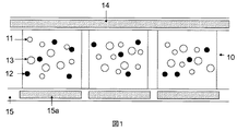
本発明の電気泳動流体は、誘電溶媒又は溶媒混合物中に分散した3タイプの顔料粒子を含む。説明を容易にするために、図1に示すように、白色粒子(11)、黒色粒子(12)及び着色粒子(色粒子又はカラー粒子:color particle)(13)として、3タイプの顔料粒子を参照することができる。しかし、3タイプの顔料粒子が、目視で対照的な色を有する限り、本発明の範囲は、いずれの色の顔料粒子も広範に含むことが理解される。 The electrophoretic fluid of the present invention comprises three types of pigment particles dispersed in a dielectric solvent or solvent mixture. For ease of explanation, as shown in FIG. 1, three types of pigment particles are used as white particles (11), black particles (12), and colored particles (color particles or color particles) (13). You can refer to it. However, as long as the three types of pigment particles have a visually contrasting color, it is understood that the scope of the invention broadly encompasses any color pigment particle.
二つの電極層の間にディスプレイ流体は、挟まれる。電極層の一つは、透明電極層(例えば、ITO)である共通電極(又はコモン電極:common electrode)(14)であり、ディスプレイデバイスの上面全体に広がる。他の電極層(15)は、画素電極(15a)の層である。流体によって表示される色の状態(着色状態又はカラーステイト:color state)は、共通電極と画素電極との間に印加される電圧によって決められる。 A display fluid is sandwiched between the two electrode layers. One of the electrode layers is a common electrode (or common electrode) (14) that is a transparent electrode layer (eg, ITO) and extends across the entire top surface of the display device. The other electrode layer (15) is a layer of the pixel electrode (15a). The color state (color state or color state) displayed by the fluid is determined by the voltage applied between the common electrode and the pixel electrode.
画素電極は、米国特許第7,046,228号に記載されており、その内容は、参照することによって本明細書に組み込まれる。薄膜トランジスタ(TFT)バックプレーン(backplane)を用いるアクティブマトリックス駆動が、画素電極の層のために言及されているが、電極が所望の機能を果たす限り、本発明の範囲は、他のタイプの電極アドレッシング(electrode addressing)を含む。 Pixel electrodes are described in US Pat. No. 7,046,228, the contents of which are hereby incorporated by reference. While active matrix driving using thin film transistor (TFT) backplanes is mentioned for the layer of pixel electrodes, the scope of the present invention covers other types of electrode addressing as long as the electrodes perform the desired function. (Electrode addressing).
白色粒子(11)について、それらは、無機顔料、例えば、TiO2、ZrO2、ZnO、Al2O3、 Sb2O3、BaSO4、PbSO4などから作ることができる。
For the white particles (11), which are inorganic pigments, for example, can be made of such TiO 2, ZrO 2, ZnO, Al 2
黒色粒子(12)について、それらは、C.I.ピグメントブラック26又は28など(例えば、マンガンフェライトブラックスピネル又は銅クロマイトブラックスピネル)又はカーボンブラックから作ることができる。 For black particles (12), they can be made from C.I. pigment black 26 or 28 (e.g. manganese ferrite black spinel or copper chromite black spinel) or carbon black.
第3タイプの顔料粒子は、例えば、赤色(又はレッド)、緑色(又はグリーン)、青色(又はブルー)、マゼンタ、シアン又はイエロー(又は黄色)等の色であってよい。このタイプの粒子のための顔料は、C.I.ピグメントPR254、PR122、PR149、PG36、PG58、PG7、PB28、PB15:3、PY138、PY150、PY155又はPY20を含み得るが、これらに限定されるものではない。それらは、カラーインデックスハンドブックである“New Pigment Application Technology”(CMC Publishing Co, Ltd, 1986)及び“Printing Ink Technology”(CMC Publishing Co, Ltd, 1984)に記載の通常使用される有機顔料である。クラリアント社(Clariant)のホスタパーム(Hostaperm:商品名)Red D3G 70-EDS、ホスタパーム Pink E-EDS、 PV fast red D3G、ホスタパーム red D3G 70、ホスタパーム Blue B2G-EDS、ホスタパーム Yellow H4G-EDS、ホスタパーム Green GNX、BASF社 イルガジン(Irgazine)red L 3630、シンクアジア(Cinquasia)Red L 4100 HD、及びイルガジンRed L 3660 HD;サンケミカル社(Sun Chemical)フタロシアニンブルー、フタロシアニングリーン、ジアリライドイエロー(diarylide yellow)又はジアリアイドAAOTイエローを例示できる。 The third type of pigment particles may be, for example, red (or red), green (or green), blue (or blue), magenta, cyan or yellow (or yellow). Pigments for this type of particles may include, but are not limited to, CI pigments PR254, PR122, PR149, PG36, PG58, PG7, PB28, PB15: 3, PY138, PY150, PY155, or PY20. . They are commonly used organic pigments described in the Color Index Handbooks “New Pigment Application Technology” (CMC Publishing Co, Ltd, 1986) and “Printing Ink Technology” (CMC Publishing Co, Ltd, 1984). Clariant's Hostaperm (trade name) Red D3G 70-EDS, Hosta Palm Pink E-EDS, PV fast red D3G, Hosta Palm red D3G 70, Hosta Palm Blue B2G-EDS, Hosta Palm Yellow H4G-EDS, Hosta Palm Green GNX , BASF Irgazine red L 3630, Cinquasia Red L 4100 HD, and Irgazine Red L 3660 HD; Sun Chemical phthalocyanine blue, phthalocyanine green, diarylide yellow or An example is Diaryide AAOT Yellow.
流体中の3タイプの顔料粒子の割合は、様々であり得る。例えば、黒色粒子は、電気泳動流体の約0.1体積% 〜 10体積%であり、好ましくは 0.5体積% 〜 5体積%をとり得;白色粒子は、電気泳動流体の約1体積% 〜 50体積%であり、好ましくは 5体積% 〜 15体積%をとり得;及び着色粒子は、電気泳動流体の約2体積% 〜 20体積%であり、好ましくは 4体積% 〜 10体積%をとり得る。 The proportion of the three types of pigment particles in the fluid can vary. For example, black particles can be from about 0.1% to 10% by volume of the electrophoretic fluid, preferably from 0.5% to 5% by volume; white particles can be from about 1% to 50% by volume of the electrophoretic fluid. And preferably can take 5% to 15% by volume; and the colored particles can take about 2% to 20% by volume of the electrophoretic fluid, preferably 4% to 10% by volume.
スイッチング速度、画像双安定性及び信頼性等のディスプレイデバイスの性能を向上させるために添加剤として含まれる流体中に他の粒状物質がありえる。 There may be other particulate materials in the fluid that are included as additives to improve the performance of the display device, such as switching speed, image bistability and reliability.
3タイプの顔料粒子が分散される溶媒は、無色透明である。高い粒子移動度のために、低粘度で、約2〜約30、好ましくは約2〜約15の範囲の誘電率を有することが好ましい。適切な誘電溶媒の例は、炭化水素、例えば、イソパー(isopar)、デカヒドロナフタレン(デカリン)、5−エチリデン−2−ノルボルネン、脂肪油、パラフィンオイル、シリコン流体、芳香族炭化水素、例えば、トルエン、キシレン、フェニルキシリルエタン、ドデシルベンゼン又はアルキルナフタレン、ハロゲン溶媒、例えば、パーフルオロデカリン、パーフルオロトルエン、パーフルオロキシレン、ジクロロベンゾトリフルオリド、3,4,5−トリクロロベンゾトリフルオリド、クロロペンタフルオロベンゼン、ジクロロノナン又はペンタクロロベンゼン、及びパーフルオロ化(又は全フッ素置換)溶媒、例えば、ミネソタ州セントポールの3M社(3M Company, St. Paul MN)からFC-43, FC-70 又は FC-5060、オレゴン州ポートランドのTCIアメリカ社(TCI America, Portland, Oregon)から低分子量ハロゲン含有ポリマー、例えば、ポリ(パーフルオロプロピレンオキサイド)、ニュージャージー州リバーエッジのハロカーボンプロダクト社(Halocarbon Product Corp., River Edge, NJ)からポリ(クロロトリフルオロエチレン)、例えば、ハロカーボンオイル、アウジモント社(Ausimont)からパーフルオロポリアルキルエーテル、例えば、ガルデン(Galden)又はデラウエア州のデュポン社(DuPont, Delaware)からクライトックスオイル及びグリースK−流体シリーズ、ダウ−コーニング社(CD-200)からポリジメチルシロキサン系シリコンオイルを含む。 The solvent in which the three types of pigment particles are dispersed is colorless and transparent. For high particle mobility, it is preferred to have a low viscosity and a dielectric constant in the range of about 2 to about 30, preferably about 2 to about 15. Examples of suitable dielectric solvents are hydrocarbons such as isopar, decahydronaphthalene (decalin), 5-ethylidene-2-norbornene, fatty oils, paraffin oil, silicone fluids, aromatic hydrocarbons such as toluene , Xylene, phenylxylylethane, dodecylbenzene or alkylnaphthalene, halogen solvents such as perfluorodecalin, perfluorotoluene, perfluoroxylene, dichlorobenzotrifluoride, 3,4,5-trichlorobenzotrifluoride, chloropentafluoro Benzene, dichlorononane or pentachlorobenzene, and perfluorinated (or perfluorinated) solvents such as FC-43, FC-70 or FC-5060 from 3M Company, St. Paul MN, Minnesota TCI candy in Portland, Oregon Low molecular weight halogen-containing polymers such as poly (perfluoropropylene oxide) from TCI America, Portland, Oregon, poly (perfluoropropylene oxide) from Halocarbon Product Corp., River Edge, NJ Chlorotrifluoroethylene), for example, halocarbon oils, perfluoropolyalkyl ethers from Audimont, for example Krytox oil and grease K-fluid from Galden or DuPont, Delaware Contains polydimethylsiloxane silicone oil from the series, Dow Corning (CD-200).
3タイプの顔料粒子の2タイプは、逆の極性の電荷を帯び、第3タイプの顔料粒子は、わずかに(又は少し)電荷を帯びる。用語「わずかに(又は少し)電荷を帯びる(又は帯電する):slightly charged」は、下記のセクションで規定する。 Two types of three types of pigment particles have a charge of opposite polarity, and a third type of pigment particles has a slight (or little) charge. The term “slightly charged” (or slightly charged) is defined in the section below.
例えば、黒色粒子が正に帯電している場合、白色粒子は負に帯電しており、着色粒子はわずかに帯電している。言い換えれば、この例では、黒色粒子と白色粒子が帯びる電荷は、着色粒子が帯びる電荷より、強い。 For example, when black particles are positively charged, white particles are negatively charged and colored particles are slightly charged. In other words, in this example, the charge of black particles and white particles is stronger than the charge of colored particles.
更に、わずかに電荷を帯びる第3タイプの粒子は、より強く帯電した他の2つのタイプの粒子のいずれか一つが帯びる電荷の極性と同じ極性の電荷を有する。 In addition, the third type of particles that are slightly charged have a charge of the same polarity as the charge of any one of the other two more strongly charged particles.
3つのタイプの顔料粒子は、種々のサイズを有し得る。一の態様において、3つのタイプの顔料粒子の一つは、他の二つのタイプより大きい。 The three types of pigment particles can have various sizes. In one embodiment, one of the three types of pigment particles is larger than the other two types.
3つのタイプの顔料粒子の中で、わずかに電荷を帯びる一つのタイプの粒子は、より大きなサイズを有することが好ましいことに注意されたい。 It should be noted that among the three types of pigment particles, one type of particle that is slightly charged preferably has a larger size.
例えば、黒色粒子及び白色粒子の両方とも相対的に小さく、それらのサイズ(動的光散乱によって測定される)は、約50nmから約800nm、より好ましくは約200nmから約700nmの範囲であり得、この例では、わずかに電荷を帯びる着色粒子は、黒色粒子及び白色粒子より、好ましくは、約2倍から約50倍、より好ましくは約2倍から約10倍大きい。 For example, both black and white particles are relatively small and their size (measured by dynamic light scattering) can range from about 50 nm to about 800 nm, more preferably from about 200 nm to about 700 nm, In this example, the slightly charged colored particles are preferably about 2 to about 50 times, more preferably about 2 to about 10 times larger than the black and white particles.
本明細書において、用語「しきい電圧」とは、ディスプレイデバイスの視野側(視界側又は表示側)に顔料粒子が現れることを生じさせること無く、一群の顔料粒子に印加することができる最大のバイアス電圧として定義される。用語「視野側(viewing side)」とは、観察者(見る人:viewer)によって画像が見られるディスプレイデバイスの側をいう。 In this specification, the term “threshold voltage” refers to the maximum value that can be applied to a group of pigment particles without causing the pigment particles to appear on the view side (view side or display side) of the display device. Defined as bias voltage. The term “viewing side” refers to the side of the display device where an image is viewed by a viewer.
本発明では、3つのタイプの顔料粒子の少なくとも一種は、トランアングル電圧駆動テスト下、しきい電圧を示し得る。 In the present invention, at least one of the three types of pigment particles can exhibit a threshold voltage under a triangle voltage drive test.
しきい電圧は、帯電顔料粒子の固有の性質又は添加剤誘起性質(又は添加剤によって誘起される性質:additive-induced property)である。 The threshold voltage is an intrinsic property or additive-induced property (or additive-induced property) of the charged pigment particles.
前者の場合、粒子間又は粒子とある基材表面との間のある引力に依存して、しきい電圧は生ずる。しきい電圧は、逆の極性の電荷を帯びた2タイプの粒子の相互作用によって、生じ得る。 In the former case, a threshold voltage is generated depending on a certain attractive force between particles or between a particle and a certain substrate surface. The threshold voltage can be generated by the interaction of two types of particles with opposite polar charges.
後者の場合、しきい電圧を達成するために、電気泳動流体のしきい値特性を誘起し又は向上するしきい剤(threshold agent)を添加することができる。しきい剤は、電気泳動流体の溶媒又は溶媒混合物中に溶解可能又は分散可能で、電荷を帯びた顔料粒子と逆の電荷を帯びる又は誘起するいずれの材料であってよい。しきい剤は、印加電圧の変化に敏感であっても敏感で無くともよい。用語「しきい剤」は、染料(又は色素)又は顔料、電解質又は高分子電解質(polyelectrolytes)、ポリマー、オリゴマー、界面活性剤、電荷制御剤などを広範に含み得る。 In the latter case, a threshold agent can be added to induce or improve the threshold characteristics of the electrophoretic fluid to achieve a threshold voltage. The threshold may be any material that is soluble or dispersible in the solvent or solvent mixture of the electrophoretic fluid and that is charged or induces a charge opposite to that of the charged pigment particles. The threshold may or may not be sensitive to changes in applied voltage. The term “thresholding agent” can broadly include dyes (or pigments) or pigments, electrolytes or polyelectrolytes, polymers, oligomers, surfactants, charge control agents, and the like.
しきい剤に関する更なる情報は、米国特許第8,115,729号にみることができる。その内容は、参照することで、本明細書に組み込まれる。 Further information regarding thresholds can be found in US Pat. No. 8,115,729. The contents of which are incorporated herein by reference.
以下は、本発明を説明する例である。 The following are examples illustrating the present invention.
例1(a)
この例は、図2に示す。黒色粒子(22)は、5Vのしきい電圧を有すると仮定する。従って、黒色粒子(22)は、もし、印加電位差が5V以下ならば、視野側(視界側又は表示側:viewing side)に移動しないであろう。
Example 1 (a)
An example of this is shown in FIG. Assume that the black particles (22) have a threshold voltage of 5V. Therefore, the black particles (22) will not move to the viewing side (viewing side or viewing side) if the applied potential difference is 5V or less.
白色顔料粒子(21)は、負に帯電し、黒色顔料粒子(22)は、正に帯電し、両方のタイプの顔料粒子は、着色粒子(色粒子又はカラー粒子:color particle)(23)より小さい。 The white pigment particles (21) are negatively charged, the black pigment particles (22) are positively charged, both types of pigment particles are more colored than colored particles (color particles) (23). small.
着色粒子(23)は、しきい電圧を有する黒色粒子と同じ極性の電荷を帯びるが、わずかに(又は少し)電荷を帯びる。用語「わずかに(又は少し)電荷を帯びる(又は帯電する):slightly charged」は、粒子の電荷のレベルが、黒色粒子又は白色粒子の電荷の強さの約50%より低く、好ましくは約5%から約30%であることを意図する。その結果、印加電位差が、黒色粒子のしきい電圧より高い場合、黒色粒子が帯びるより強い電荷強度のために、黒色粒子は、着色粒子(23)より速く移動する。 The colored particles (23) are charged with the same polarity as the black particles having a threshold voltage, but are slightly (or slightly) charged. The term “slightly charged” means that the level of charge of the particles is less than about 50% of the charge intensity of the black or white particles, preferably about 5 % To about 30%. As a result, when the applied potential difference is higher than the threshold voltage of the black particles, the black particles move faster than the colored particles (23) because of the stronger charge intensity that the black particles take on.
図2aでは、印加電位差が+15Vである。この場合、白色粒子(21)は、移動して画素電極(25)に又はその近傍に存在し、黒色粒子(22)と着色粒子(23)は、移動して共通電極(24)に又はその近傍に存在する。その結果、視野側で黒色が見られる。着色粒子(23)は、共通電極(24)の方に移動するが、それらのより低い電荷強度とより大きなサイズのために、それらは、黒色粒子より遅く移動する。 In FIG. 2a, the applied potential difference is + 15V. In this case, the white particles (21) move and exist at or near the pixel electrode (25), and the black particles (22) and the colored particles (23) move and move to the common electrode (24) or its It exists in the vicinity. As a result, black is seen on the visual field side. The colored particles (23) move towards the common electrode (24), but due to their lower charge intensity and larger size they move slower than the black particles.
図2bでは、−15Vの電位差を印加する場合、白色粒子(21)は、移動して共通電極(24)に又はその近傍に存在し、黒色粒子と着色粒子は、移動して画素電極(25)に又はその近傍に存在する。その結果、視野側で、白色が見られる。 In FIG. 2b, when a potential difference of −15V is applied, the white particles (21) move and exist at or near the common electrode (24), and the black particles and the colored particles move and move to the pixel electrode (25 ) Or in the vicinity thereof. As a result, white is seen on the viewing side.
着色粒子(23)は、それらも正の電荷を帯びているので、画素電極の方に移動するが、より低い電荷強度及びより大きいサイズのために、黒色粒子より遅く移動する。 The colored particles (23) move towards the pixel electrode because they are also positively charged, but move slower than the black particles because of the lower charge intensity and larger size.
図2cでは、印加電位差は、+5Vに変わる。この場合、負に帯電した白色粒子(21)は、画素電極(25)の方に移動する。黒色粒子(22)は、そのしきい電圧が5Vなので、ほとんど動かない。着色粒子(23)は、顕著なしきい電圧を有さないという事実から、移動して共通電極(24)に又はその近傍に存在し、その結果、視野側で着色粒子の色が見られる。 In FIG. 2c, the applied potential difference changes to + 5V. In this case, the negatively charged white particles (21) move toward the pixel electrode (25). The black particles (22) hardly move because their threshold voltage is 5V. Due to the fact that the colored particles (23) do not have a significant threshold voltage, they move and are present at or near the common electrode (24), so that the color of the colored particles is seen on the viewing side.
図2bの白色状態から、図2cの着色状態(色の状態又はカラー状態:color state)への駆動は、次のように要約することができる: Driving from the white state of FIG. 2b to the colored state of FIG. 2c (color state or color state) can be summarized as follows:
第1タイプの顔料粒子、第2タイプの顔料粒子及び第3タイプの顔料粒子を含み、それらの全ては、溶媒又は溶媒混合物に分散される電気泳動流体で満たされたディスプレイセルを含む電気泳動ディスプレイの駆動方法であって、
(a)第1タイプの顔料粒子と第2タイプの顔料粒子は、反対の極性の電荷を帯び;
(b)第3タイプの顔料粒子は、第2タイプの顔料粒子と同じ極性の電荷を有するが、より低強度であり;
(c)第2タイプの顔料粒子は、しきい電圧を有し、
第1タイプの顔料粒子の色の状態から、第3タイプの顔料の色の状態に、第2タイプの顔料粒子のしきい電圧と同じ又はそれより低い電圧を印加することによって駆動することを含む、電気泳動ディスプレイの駆動方法。
An electrophoretic display comprising a display cell filled with an electrophoretic fluid dispersed in a solvent or solvent mixture comprising a first type of pigment particles, a second type of pigment particles and a third type of pigment particles Driving method,
(A) the first type of pigment particles and the second type of pigment particles have opposite polar charges;
(B) the third type pigment particles have the same polarity of charge as the second type pigment particles, but have a lower intensity;
(C) the second type pigment particles have a threshold voltage;
Driving by applying a voltage equal to or lower than a threshold voltage of the second type pigment particles from the color state of the first type pigment particles to the color state of the third type pigment particles. , Driving method of electrophoretic display.
この方法では、図2に示すように、第1タイプの顔料粒子(21)は、白色であり、第2タイプの顔料粒子(22)は、黒色であり、第3タイプの顔料粒子(23)は、赤色である。 In this method, as shown in FIG. 2, the first type pigment particles (21) are white, the second type pigment particles (22) are black, and the third type pigment particles (23). Is red.
第3タイプの顔料の着色状態、即ち、赤色にディスプレイを駆動するために(図2c参照)、第1タイプの顔料の色の状態から(図2b参照)、方法は開始する。 In order to drive the color state of the third type pigment, ie red (see FIG. 2c), the method starts from the color state of the first type pigment (see FIG. 2b).
図2bでは、第1タイプの顔料粒子(即ち、白色)は、共通電極(24)に、又はその近傍に存在し、第2及び第3タイプの顔料粒子(即ち、黒色及び赤色)は、画素電極(25)に又はその近傍に存在する。第2タイプの顔料粒子(即ち、黒色)のしきい電圧と同じ又はより低い電圧を印加すると、第1タイプの顔料粒子(即ち、白色)は、下方に下がり、第3タイプの顔料粒子(即ち、赤色)は、共通電極(24)の方に上がり、視野側に到達し、そして、第2タイプの顔料粒子(即ち、黒色)は、そのしきい電圧のために、ほとんど移動しない。 In FIG. 2b, the first type of pigment particles (ie white) is present at or near the common electrode (24) and the second and third types of pigment particles (ie black and red) are pixels. Present at or near the electrode (25). When a voltage equal to or lower than the threshold voltage of the second type of pigment particles (i.e., black) is applied, the first type of pigment particles (i.e., white) falls downward and the third type of pigment particles (i.e., white). , Red) rises towards the common electrode (24), reaches the viewing side, and the second type of pigment particles (ie, black) moves very little because of its threshold voltage.
この状況で、第3タイプの粒子の色が視野側で見られる場合、他の二つのタイプの粒子は、非視野側(視野側と反対側)で、混合され、その結果、第1タイプの粒子の色と第2タイプの粒子の色の間の中間色状態を生ずる。もし、第1及び第2タイプの粒子が、黒色と白色で有り、第3タイプの粒子が赤色である場合、図2(c)のように、赤色が視野側で見られる場合、灰色が非視野側で見られる。 In this situation, if the color of the third type of particles is seen on the viewing side, the other two types of particles are mixed on the non-viewing side (opposite to the viewing side), so that the first type of particles are mixed. An intermediate color state between the color of the particle and the color of the second type of particle is produced. If the first and second type particles are black and white, and the third type particle is red, as shown in FIG. 2C, when red is seen on the viewing side, gray is not Seen on the field of view.
図2cの状況で、駆動方法は、理想的には、色の明度(即ち、黒色粒子が見えることを防止する)及び色の純度(即ち、白色粒子が見えることを防止する)の両方を確保するであろう。しかし、現実的には、この望ましい結果は、粒子サイズ分布、粒子電荷分布及び他の要因を含む、種々の理由のために、制御することが困難である。 In the situation of FIG. 2c, the driving method ideally ensures both color brightness (ie, preventing black particles from being seen) and color purity (ie, preventing white particles from being seen). Will do. In reality, however, this desirable result is difficult to control for a variety of reasons, including particle size distribution, particle charge distribution, and other factors.
これに対する一つの解は、第1タイプの顔料粒子の色の状態(即ち、白色)から、第3タイプの顔料粒子の色の状態(即ち、赤色)に、駆動する前に、振動波形(shaking waveform)を使用することである。振動波形は、多くのサイクルの間に一組の反対の駆動パルスを繰り返すことからなる。例えば、振動波形は、20msecの間に+15Vのパルス及び20msecの間に−15Vのパルスからなり得、そのような一組のパルスが、50回繰り返される。そのような振動波形の合計の時間は、2000msecであろう(図8参照)。 One solution to this is to move from the color state of the first type of pigment particles (ie, white) to the color state of the third type of pigment particles (ie, red) before driving. waveform). The oscillating waveform consists of repeating a set of opposite drive pulses during many cycles. For example, the vibration waveform may consist of a + 15V pulse for 20 msec and a -15V pulse for 20 msec, and such a set of pulses is repeated 50 times. The total time for such a vibration waveform would be 2000 msec (see FIG. 8).
実際のところ、少なくとも10回の繰り返し(即ち、10組の正のパルスと負のパルス)であり得る。 In fact, there can be at least 10 repetitions (ie, 10 sets of positive and negative pulses).
駆動電圧を印加する前に、光学(又は視覚的)状態(黒色、白色又は赤色)にかかわらず、振動波形をディスプレイに印加することできる。振動波形を印加した後、光学状態は純粋な白色、純粋な黒色又は純粋な赤色では無いであろう。そのかわり、着色状態は、3タイプの顔料粒子の混合物からのものであろう。 Before applying the drive voltage, a vibration waveform can be applied to the display regardless of the optical (or visual) state (black, white or red). After applying the vibration waveform, the optical state will not be pure white, pure black or pure red. Instead, the colored state will be from a mixture of three types of pigment particles.
上述の方法のために、振動波形を第1タイプの顔料粒子の着色状態(即ち、白色)にディスプレイを駆動する前に印加する。この印加した振動波形を用いると、白色状態は、振動波形を用いない場合とたとえある程度同様であっても、第3タイプの顔料粒子の着色状態(即ち、赤色)は、振動波形を用いない場合より、色の明度と色の純度の両方に関して、著しく良好である。このことは、赤色粒子から黒色粒子の分離と同様、赤色粒子から白色粒子のより良好な分離を示す。 For the method described above, the vibration waveform is applied to the colored state of the first type of pigment particles (ie, white) before driving the display. When this applied vibration waveform is used, even if the white state is somewhat similar to the case where the vibration waveform is not used, the colored state of the third type pigment particles (ie, red) is the case where the vibration waveform is not used. Thus, it is significantly better both in terms of color brightness and color purity. This indicates a better separation of white particles from red particles as well as separation of black particles from red particles.
振動波形中の各々の駆動パルスを、完全な黒色の状態(full black state)から完全な白色の状態(full white state)に、要する駆動時間の50%を超えない(又は30%、10%又は5%を超えない)時間、印加する。例えば、もし、完全黒色状態から完全白色状態に又は逆にディスプレイデバイスを駆動するために300msec要するならば、振動波形は、正の及び負のパルスからなり、各々150msec以下の時間印加され得る。実際、パルスはより短い方が好ましい。 Each drive pulse in the vibration waveform does not exceed 50% of the drive time required (or 30%, 10%, or from full black state to full white state) Apply for a time not exceeding 5%). For example, if it takes 300 msec to drive a display device from a full black state to a full white state or vice versa, the vibration waveform can consist of positive and negative pulses, each being applied for a period of 150 msec or less. In fact, shorter pulses are preferred.
例1(b)
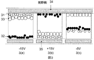
図3に示すような別の設計において、白色粒子(31)は、5Vのしきい電圧を有すると仮定する。従って、白色粒子(31)は、もし印加電位差が5V以下であれば、視野側に移動しないであろう。
Example 1 (b)
In another design as shown in FIG. 3, it is assumed that the white particles (31) have a threshold voltage of 5V. Therefore, the white particles (31) will not move to the field of view if the applied potential difference is 5V or less.
白色顔料粒子(31)は、負の電荷を帯び、黒色顔料粒子(32)は、正の電荷を帯び、両方のタイプの顔料粒子は、着色粒子(色粒子又はカラー粒子:color particle)(33)より小さい。 The white pigment particles (31) are negatively charged, the black pigment particles (32) are positively charged, and both types of pigment particles are colored particles (color particles or color particles) (33 ) Is smaller.
着色粒子(33)は、しきい電圧を有する白色粒子と同じ極性の電荷を帯びるが、わずかに(又は少し)電荷を帯びる。用語「わずかに(又は少し)電荷を帯びる(又は帯電する):slightly charged」とは、上述の例1(a)で規定した通りである。その結果、白色粒子のしきい電圧より印加電位差がより高い場合、より強い電荷強度を帯びているので、白色粒子は着色粒子(33)より速く動く。 The colored particles (33) are charged with the same polarity as the white particles having a threshold voltage, but are slightly (or slightly) charged. The term “slightly charged” (or slightly charged) is as defined in Example 1 (a) above. As a result, when the applied potential difference is higher than the threshold voltage of the white particles, the white particles move faster than the colored particles (33) because they have a stronger charge intensity.
図3aにおいて、印加電位差は−15Vである。この場合、黒色粒子(32)は、移動して画素電極(35)に又はその近傍に存在し、白色粒子(31)及び着色粒子(33)は、移動して共通電極(34)に又はその近傍に存在する。その結果、視野側で白色が見られる。着色粒子(33)は、共通電極(34)の方に移動するが、それらの低い電荷強度とより大きなサイズのため、それらは、白色粒子より遅く移動する。 In FIG. 3a, the applied potential difference is -15V. In this case, the black particles (32) move and exist at or near the pixel electrode (35), and the white particles (31) and the colored particles (33) move and move to the common electrode (34) or its It exists in the vicinity. As a result, white is seen on the viewing side. The colored particles (33) move towards the common electrode (34), but due to their low charge intensity and larger size they move slower than the white particles.
図3bにおいて、+15Vの電位差を印加すると、白色粒子(31)は、移動して画素電極(35)に又はその近傍に存在し、黒色粒子は、移動して共通電極(34)に又はその近傍に存在する。その結果、視野側で黒色が見られる。 In FIG. 3b, when a potential difference of + 15V is applied, the white particles (31) move and exist at or near the pixel electrode (35), and the black particles move and move at or near the common electrode (34). Exists. As a result, black is seen on the visual field side.
着色粒子(33)は、負の電荷を帯びるので、画素電極の方に移動する。しかし、それらの低い電荷強度とより大きなサイズのため、それらは、白色粒子より遅く移動する。 Since the colored particles (33) are negatively charged, they move toward the pixel electrode. However, because of their low charge intensity and larger size, they move slower than white particles.
図3cにおいて、印加電位差は−5Vに変わった。この場合、正に帯電した黒色粒子(32)は、画素電極(35)の方に移動する。白色粒子(32)は、5Vのしきい電圧のために、ほとんど移動しない。着色粒子(33)は顕著なしきい電圧を有さないという事実のために、それらは、共通電極(34)に又はその近傍に移動し、その結果、着色粒子の色が視野側から見られる。 In FIG. 3c, the applied potential difference changed to -5V. In this case, the positively charged black particles (32) move toward the pixel electrode (35). White particles (32) move very little due to a threshold voltage of 5V. Due to the fact that the colored particles (33) do not have a significant threshold voltage, they move to or near the common electrode (34) so that the color of the colored particles is seen from the viewing side.
例1(c)
図4に示すように、しきい電圧を有する着色粒子(色粒子又はカラー粒子:color particle)を含むこともできる。この場合、印加電位差が5V以下であるならば、着色粒子(43)は、視野側に移動しないであろう。
Example 1 (c)
As shown in FIG. 4, colored particles (color particles or color particles) having a threshold voltage may be included. In this case, if the applied potential difference is 5 V or less, the colored particles (43) will not move to the visual field side.
黒色顔料粒子(42)は、負に帯電し、着色顔料粒子(43)は、正に帯電し、両方のタイプの顔料粒子は、白色粒子(41)より小さい。 The black pigment particles (42) are negatively charged, the colored pigment particles (43) are positively charged, and both types of pigment particles are smaller than the white particles (41).
白色粒子(41)は、しきい電圧を有する着色粒子と同じ極性の電荷を帯びるが、わずかに(又は少し)電荷を帯びる。用語「わずかに(又は少し)電荷を帯びる(又は帯電する):slightly charged」は、上述の例1(a)で規定した通りである。その結果、着色粒子のしきい電圧より印加電位差がより高い場合、より強い電荷強度を帯びるので、着色粒子は白色粒子(41)より速く動く。 The white particles (41) are charged with the same polarity as the colored particles having a threshold voltage, but are slightly (or slightly) charged. The term “slightly charged” (or slightly charged) is as defined in Example 1 (a) above. As a result, when the applied potential difference is higher than the threshold voltage of the colored particles, the colored particles move faster than the white particles (41) because they have a stronger charge intensity.
図4aにおいて、印加電位差は+15Vである。この場合、黒色粒子(42)は、移動して画素電極(45)に又はその近傍に存在し、白色粒子(41)及び着色粒子(43)は、移動して共通電極(44)に又はその近傍に存在する。その結果、視野側で着色粒子の色が見られる。白色粒子(41)は、共通電極(44)の方に移動するが、それらの低い電荷強度とより大きなサイズのため、それらは、着色粒子より遅く移動する。 In FIG. 4a, the applied potential difference is + 15V. In this case, the black particles (42) move and exist at or near the pixel electrode (45), and the white particles (41) and the colored particles (43) move and move to the common electrode (44) or its It exists in the vicinity. As a result, the color of the colored particles can be seen on the visual field side. White particles (41) move towards the common electrode (44), but due to their low charge intensity and larger size they move slower than the colored particles.
図4bにおいて、−15Vの電位差を印加する場合、着色粒子(43)は、移動して画素電極(45)に又はその近傍に存在し、黒色粒子は、移動して共通電極(44)に又はその近傍に存在する。その結果、視野側で黒色が見られる。 In FIG. 4b, when a potential difference of −15 V is applied, the colored particles (43) move and exist at or near the pixel electrode (45), and the black particles move to the common electrode (44) or It exists in the vicinity. As a result, black is seen on the visual field side.
白色粒子(41)は、正に帯電しているので、画素電極の方に移動する。しかし、それらの低い電荷強度とより大きなサイズのため、それらは、着色粒子より遅く移動する。 Since the white particles (41) are positively charged, they move toward the pixel electrode. However, because of their low charge intensity and larger size, they move slower than colored particles.
図4cにおいて、印加電位差は+5Vに変わった。この場合、負に帯電した黒色粒子(42)は、画素電極(45)の方に移動する。着色粒子(43)は、5Vのしきい電圧のために、ほとんど移動しない。白色粒子(41)は顕著なしきい電圧を有さないという事実のために、それらは、移動して共通電極(44)に又はその近傍に存在し、その結果、白色が視野側から見える。 In FIG. 4c, the applied potential difference changed to + 5V. In this case, the negatively charged black particles (42) move toward the pixel electrode (45). The colored particles (43) move very little because of the 5V threshold voltage. Due to the fact that the white particles (41) do not have a significant threshold voltage, they move and are present at or near the common electrode (44), so that white is visible from the viewing side.
本発明の他の態様において、全ての3つのタイプの顔料粒子は、異なるレベルの電荷強度を有し、従って、異なるレベルの移動度(又は移動性)を有する。 In other embodiments of the invention, all three types of pigment particles have different levels of charge intensity and thus have different levels of mobility (or mobility).
例えば、第1及び第2タイプの粒子は、逆の極性の電荷を帯びる、そして第1タイプの粒子の電荷強度は、第2タイプの粒子の電荷強度の、少なくとも約2倍、好ましくは約3倍〜約15倍であり、又はその逆である。第3タイプの粒子の電荷強度は、第1又は第2タイプの粒子の、どちらかより小さい電荷強度を有する粒子の電荷強度の、約50%より小さく、好ましくは約5%〜約30%である。具体的な例では、もし黒色粒子が白色粒子の2倍の電荷強度を有するならば、着色粒子は白色粒子の電荷強度の50%より小さい電荷強度を有しえる。 For example, the first and second types of particles carry opposite polarity charges, and the charge intensity of the first type particles is at least about twice the charge intensity of the second type particles, preferably about 3 Times to about 15 times, or vice versa. The charge intensity of the third type particles is less than about 50%, preferably from about 5% to about 30%, of the charge intensity of the particles having the smaller charge intensity of either the first or second type particles. is there. In a specific example, if the black particles have twice the charge intensity of the white particles, the colored particles can have a charge intensity that is less than 50% of the charge intensity of the white particles.
最も小さい電荷強度を帯びる粒子が、他の二つのタイプの粒子より大きいことが好ましい。 It is preferred that the particles with the lowest charge intensity are larger than the other two types of particles.
異なるレベルの電荷強度のために、三タイプの顔料粒子は、異なるレベルの移動性を有するであろう。電荷強度が高いほど、粒子はより速く移動する。下記の例は、本発明のこの態様を説明する。 Because of the different levels of charge intensity, the three types of pigment particles will have different levels of mobility. The higher the charge intensity, the faster the particles move. The following example illustrates this aspect of the invention.
例2
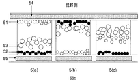
この例を、図5に示す。黒色粒子(52)の電荷強度は、白色粒子(51)の2倍の電荷強度であり、従って、黒色粒子は白色粒子より2倍速く移動すると仮定する。着色粒子(53)は、白色粒子の50%の電荷強度より小さい電荷強度を有する。
Example 2
An example of this is shown in FIG. The charge intensity of the black particles (52) is twice that of the white particles (51), so it is assumed that the black particles move twice as fast as the white particles. The colored particles (53) have a charge intensity that is less than the 50% charge intensity of the white particles.
従って、黒色粒子が共通電極と画素電極の間(d)を移動するために駆動時間tを要し、同じ距離dを移動するために、白色粒子は2t要し、着色粒子は少なくとも4t要す。 Accordingly, it takes a drive time t for the black particles to move between the common electrode and the pixel electrode (d), and for moving the same distance d, the white particles require 2t and the colored particles require at least 4t. .
更に、黒色粒子は正に帯電し、白色粒子は負に帯電している。着色粒子は、最も大きな強度を有する粒子、即ち、この場合は黒色粒子、と同じ極性の電荷を帯びる。 Further, the black particles are positively charged and the white particles are negatively charged. The colored particles are charged with the same polarity as the particles having the greatest intensity, i.e. in this case black particles.
図5aにおいて、負の電位差を、共通電極(54)と画素電極(55)に印加する場合、2tの駆動時間後、白色顔料粒子(51)は共通電極(即ち、視野側)に又はその近傍に存在し、黒色顔料粒子(52)は、画素電極に又はその近傍に存在するであろう。その結果、白色状態が見られる。着色粒子(53)は、より大きなサイズ及びより低い電荷強度/より低い移動度のために、少し移動するであろう。更に、正に帯電しているので、画素電極(55)の方に移動するであろう。 In FIG. 5a, when a negative potential difference is applied to the common electrode (54) and the pixel electrode (55), after 2t drive time, the white pigment particles (51) are at or near the common electrode (ie, the viewing side). And black pigment particles (52) will be present at or near the pixel electrode. As a result, a white state is seen. The colored particles (53) will move a little due to the larger size and lower charge intensity / lower mobility. Furthermore, since it is positively charged, it will move towards the pixel electrode (55).
図5bにおいて、正の電位差を、共通電極(54)と画素電極(55)に印加する場合、2tの駆動時間後、黒色顔料粒子(52)は共通電極に又はその近傍に存在し、白色顔料粒子(51)は、画素電極に又はその近傍に存在するであろう。その結果。黒色状態が見られる。 In FIG. 5b, when a positive potential difference is applied to the common electrode (54) and the pixel electrode (55), after 2t drive time, the black pigment particles (52) are present at or near the common electrode, and the white pigment Particles (51) will be present at or near the pixel electrode. as a result. A black state is seen.
低電荷強度及び低移動性のため、着色粒子は、ほとんど移動しないであろう。黒色粒子と着色粒子は同じ極性の電荷を帯びているが、黒色粒子は、より高い電荷強度とよりサイズが小さいので、移動して共通電極のより近くに存在するであろう。 Due to the low charge intensity and low mobility, the colored particles will hardly move. Black particles and colored particles carry the same polarity charge, but black particles will move and be closer to the common electrode because of their higher charge intensity and smaller size.
図5cのステップの前に、白色粒子は画素電極(55)に又はその近傍に存在し、黒色粒子と着色粒子は共通電極(54)に又はその近傍に存在することが好ましい。図5cにおいて、共通電極(54)と画素電極(55)の間に、負の電位差を印加すると、駆動時間tの後、底部の白色粒子(51)は、共通電極と画素電極の間の領域、およそ中間レベルの領域に移動し、一方、黒色粒子(52)は、全部の距離dを移動して、画素電極に又はその近傍に存在するであろう。着色粒子は、下方に短い距離を移動するであろうが、共通電極のより近くにとどまるであろう。その結果、着色粒子(53)の色が視野側で見られる。 Prior to the step of FIG. 5c, white particles are preferably present at or near the pixel electrode (55), and black particles and colored particles are preferably present at or near the common electrode (54). In FIG. 5c, when a negative potential difference is applied between the common electrode (54) and the pixel electrode (55), after the driving time t, the white particles (51) at the bottom become a region between the common electrode and the pixel electrode. The black particles (52) will be at or near the pixel electrode, moving the entire distance d. The colored particles will travel a short distance down, but will stay closer to the common electrode. As a result, the color of the colored particles (53) can be seen on the visual field side.
この例で示すように、三つの光学状態の間のスイッチングは、従って、駆動タイムフレーム(又は時間:driving time frame)、駆動強度(又は駆動の大きさ:driving amplitude)又はその両方を制御することによって達成することができる。 As shown in this example, switching between the three optical states thus controls the driving time frame (or driving time frame), driving intensity (or driving amplitude) or both. Can be achieved.
この例でより大きくより遅く移動する粒子は、着色粒子である。しかし、設計は、ニーズに応じて種々変わり得る。黒色又は白色粒子を、より大きくより遅く移動する粒子にすることも可能である。 The larger and slower moving particles in this example are colored particles. However, the design can vary depending on the needs. It is also possible to make black or white particles larger and slower moving.
電気泳動ディスプレイデバイスの電気泳動流体は、ディスプレイセル内に満たされる。ディスプレイセルは、米国特許第6,930,818に記載されたようなマイクロカップでありえる。その内容は、参照することによって本明細書に組み込まれる。ディスプレイセルは、形状やサイズにかかわらず、他のタイプのマイクロコンテナ、例えば、マイクロカプセル、マイクロチャンネル又は均等物でもありえる。これらの全ては、本願発明の範囲内にある。 The electrophoretic fluid of the electrophoretic display device is filled into the display cell. The display cell can be a microcup as described in US Pat. No. 6,930,818. The contents of which are hereby incorporated by reference. The display cells can be other types of microcontainers, eg, microcapsules, microchannels, or the like, regardless of shape or size. All of these are within the scope of the present invention.
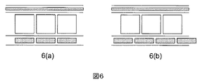
本発明の一の態様において、本発明の電気泳動流体を使用するディスプレイデバイスは、ハイライト(高光量又は高照度:high-light)ディスプレイデバイスであり、この態様において、着色粒子は、全てのディスプレイセル内で同じ色である。各ディスプレイセルは、そのようなハイライトディスプレイデバイス内で画素になるであろう。更に、図6に示すように、ディスプレイセルは、画素電極と整列することができ(図6a参照)、又は画素電極と整列しないこともできる(図6b参照)。 In one embodiment of the present invention, the display device using the electrophoretic fluid of the present invention is a highlight (high light or high-light) display device, and in this embodiment, the colored particles are present in all displays. Same color in the cell. Each display cell will be a pixel in such a highlight display device. Further, as shown in FIG. 6, the display cell may be aligned with the pixel electrode (see FIG. 6a) or may not be aligned with the pixel electrode (see FIG. 6b).
もう一つの態様において、本発明の電気泳動流体を用いるディスプレイデバイスは、多色(マルチカラー)ディスプレイデバイスでありえる。この態様において、着色粒子は、ディスプレイセルで色が異なる。この態様において、ディスプレイセルと画素電極は整列している。 In another embodiment, the display device using the electrophoretic fluid of the present invention can be a multicolor display device. In this embodiment, the colored particles have different colors in the display cell. In this embodiment, the display cell and the pixel electrode are aligned.
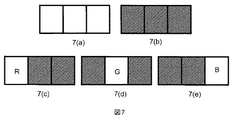
図7は、本発明のディスプレイデバイスを用いて、如何に多色を表示するかを示す。各々のディスプレイセルは、サブピクセル(sub-pixel)を意味し、各々のサブピクセルは、三つのサブピクセルを有する。三つのディスプレイセルは、各々サブピクセルを意味し、第3タイプの顔料粒子が、各々、赤色、緑色及び青色である本発明の電気泳動流体で満たされている。 FIG. 7 shows how multiple colors are displayed using the display device of the present invention. Each display cell represents a sub-pixel, and each sub-pixel has three sub-pixels. The three display cells each represent a sub-pixel, and the third type pigment particles are filled with the electrophoretic fluid of the present invention, which is red, green and blue, respectively.
図7aにおいて、白色の画素を要する場合、全ての三つのサブピクセルは白色状態に変えられる。図7bにおいて、黒色の画素を要する場合、全ての三つのサブピクセルは黒色状態に変えられる。図7cにおいて、赤色の画素を要する場合、サブピクセルの一つは赤色に変えられ、残りの二つのサブピクセルは最大の彩度のために黒色状態に変えられる。同様に、図7d及び図7eは、各々緑色及び青色を表示する。別法では、図7c、7d及び7eにおいて、サブピクセルの一つが、着色状態に駆動され、残りの二つは最大の明度(又は光度)のために(彩度を犠牲にして)白色状態に駆動される。更に、別法では、図7c、7d及び7eにおいて、サブピクセルの一つが、着色状態に駆動され、残りの二つのサブピクセルは、各々黒色状態と白色状態に駆動される。 In FIG. 7a, if a white pixel is required, all three sub-pixels are changed to a white state. In FIG. 7b, if a black pixel is required, all three sub-pixels are changed to a black state. In FIG. 7c, if a red pixel is required, one of the sub-pixels is changed to red and the remaining two sub-pixels are changed to the black state for maximum saturation. Similarly, FIGS. 7d and 7e display green and blue, respectively. Alternatively, in FIGS. 7c, 7d and 7e, one of the sub-pixels is driven into the colored state and the other two are in the white state (at the expense of saturation) for maximum brightness (or luminosity). Driven. Further, alternatively, in FIGS. 7c, 7d and 7e, one of the sub-pixels is driven to a colored state and the remaining two sub-pixels are driven to a black state and a white state, respectively.
本発明を、その具体的な態様を参照して説明したが、本発明の真の精神及び範囲から離れることなく、種々の変更が可能であり、均等物で置き換え可能であることを、当業者であれば、理解されるべきである。更に、本発明の目的及び範囲に、特定の状況、材料、組成物、プロセス、プロセスの工程又は複数の工程を適合させるために、多くの変更が可能である。全てのそのような変更は添付された特許請求の範囲内にあるように意図される。 While the invention has been described with reference to specific embodiments thereof, those skilled in the art will recognize that various modifications and equivalents can be made without departing from the true spirit and scope of the invention. If so, it should be understood. In addition, many modifications may be made to adapt a particular situation, material, composition of matter, process, process step or steps, to the objective and scope of the present invention. All such modifications are intended to be within the scope of the appended claims.
本発明を、その具体的な態様を参照して説明したが、本発明の真の精神及び範囲から離れることなく、種々の変更が可能であり、均等物で置き換え可能であることを、当業者であれば、理解されるべきである。更に、本発明の目的及び範囲に、特定の状況、材料、組成物、プロセス、プロセスの工程又は複数の工程を適合させるために、多くの変更が可能である。全てのそのような変更は添付された特許請求の範囲内にあるように意図される。
本明細書には、下記態様が含まれる。
1. 第1タイプの顔料粒子、第2タイプの顔料粒子及び第3タイプの顔料粒子を含む電気泳動流体であって、それらの全ては、溶媒又は溶媒混合物に分散され、
(a)第1タイプの顔料粒子と第2タイプの顔料粒子は、反対の極性の電荷を帯び;
(b)第3タイプの顔料粒子は、第2タイプの顔料粒子と同じ極性の電荷を帯びるが、より強度が低く;
(c)第2タイプの顔料粒子は、しきい電圧を有する、電気泳動流体。
2. 第1タイプの顔料粒子と、第2タイプの顔料粒子は、各々、黒色及び白色である、上記1に記載の電気泳動流体。
3. 第3タイプの顔料粒子は、白色でも、黒色でもない、上記1に記載の電気泳動流体。
4. 第3タイプの顔料粒子は、赤色、緑色及び青色からなる群から選択される色である、上記3に記載の電気泳動流体。
5. 第3タイプの顔料粒子は、第1タイプの顔料粒子又は第2タイプの顔料粒子より大きい、上記1に記載の電気泳動流体。
6. 第3タイプの顔料粒子は、第1タイプの顔料粒子又は第2タイプの顔料粒子より、約2倍〜約50倍大きい、上記5に記載の電気泳動流体。
7. 第3タイプの顔料粒子は、第1タイプの顔料粒子又は第2タイプの顔料粒子の電荷強度の約50%より小さい電荷レベルを有する、上記1に記載の電気泳動流体。
8. しきい電圧は、第2タイプの顔料粒子の固有の特性である、上記1に記載の電気泳動流体。
9. しきい電圧は、添加剤によって誘起される性質である、上記1に記載の電気泳動流体。
10. しきい電圧は、反対の電荷を帯びる粒子の相互作用による、上記1に記載の電気泳動流体。
11. 上記1に記載の流体で満たされるディスプレイセルを含むディスプレイデバイスであって、
共通電極層と画素電極層との間に、ディスプレイセルが挟まれる、ディスプレイデバイス。
12. ディスプレイセルは、マイクロカップである、上記11に記載のディスプレイデバイス。
13. ディスプレイセルは、マイクロカプセルである、上記11に記載のディスプレイデバイス。
14. ディスプレイセルは、画素電極と整列する、上記11に記載のディスプレイデバイス。
15. ディスプレイセルは、画素電極と整列しない、上記11に記載のディスプレイデバイス。
16. 第3タイプの顔料粒子は、全てのディスプレイセルで同色である、上記11に記載のディスプレイデバイス。
17. 第3タイプの顔料粒子は、ディスプレイセルで異なる色である、上記11に記載のディスプレイデバイス。
18. 第2タイプの顔料粒子のしきい電圧と同じ又は低い電圧を印加することによって、第1タイプの顔料粒子の色の状態から、第3タイプの顔料粒子の色の状態に駆動することを含む、上記11に記載のディスプレイデバイスの駆動方法。
19. 第1タイプの顔料粒子と、第2タイプの顔料粒子は、各々、黒色及び白色である、上記18に記載の方法。
20. 第3タイプの顔料粒子は、白色でも、黒色でもない、上記18に記載の方法。
21. 第3タイプの顔料粒子は、赤色、緑色、青色、イエロー、シアン及びマゼンタからなる群から選択される色である、上記20に記載の方法。
22. 第3タイプの顔料粒子は、第1タイプの顔料粒子又は第2タイプの顔料粒子の電荷強度の50%より小さい電荷レベルを有する、上記18に記載の方法。
23. 第3タイプの顔料粒子は、第1タイプの顔料粒子及び第2タイプの顔料粒子より大きい、上記18に記載の方法。
24. 第3タイプの顔料粒子は、第1タイプの顔料粒子又は第2タイプの顔料粒子より、約2倍〜約50倍大きい、上記23に記載の方法。
25. ディスプレイが、第1タイプの顔料粒子の色の状態に駆動される前に、振動波形を加えることを更に含む、上記18に記載の方法。
26. 振動波形は、多くのサイクルの間に、一組の反対の駆動パルスを繰り返すことからなる、上記25に記載の方法。
27. 第1タイプの顔料粒子の完全な色の状態から、第2タイプの顔料粒子の完全な色の状態に駆動するために、又はその逆のために、必要とされる時間の半分以下の時間、各々の駆動パルスを印加する、上記25に記載の方法。
28. 第3タイプの顔料粒子の色が、視野側で見られ、第1タイプの顔料粒子と、第2タイプの顔料粒子は、視野側と反対側に集まり、第1タイプの顔料粒子の色と、第2タイプの顔料粒子の色の中間色を生ずる、上記18に記載の方法。
29. 印加電圧は、第2タイプの顔料粒子と同じ極性を有する、上記18に記載の方法。
While the invention has been described with reference to specific embodiments thereof, those skilled in the art will recognize that various modifications and equivalents can be made without departing from the true spirit and scope of the invention. If so, it should be understood. In addition, many modifications may be made to adapt a particular situation, material, composition of matter, process, process step or steps, to the objective and scope of the present invention. All such modifications are intended to be within the scope of the appended claims.
The present specification includes the following embodiments.
1. An electrophoretic fluid comprising a first type of pigment particles, a second type of pigment particles and a third type of pigment particles, all of which are dispersed in a solvent or solvent mixture;
(A) the first type of pigment particles and the second type of pigment particles have opposite polar charges;
(B) the third type pigment particles have the same polarity of charge as the second type pigment particles but are less intense;
(C) The electrophoretic fluid in which the second type of pigment particles has a threshold voltage.
2. 2. The electrophoretic fluid according to 1 above, wherein the first type pigment particles and the second type pigment particles are black and white, respectively.
3. The electrophoretic fluid according to 1 above, wherein the third type of pigment particles is neither white nor black.
4). 4. The electrophoretic fluid according to 3 above, wherein the third type of pigment particles is a color selected from the group consisting of red, green, and blue.
5. 2. The electrophoretic fluid according to 1 above, wherein the third type pigment particles are larger than the first type pigment particles or the second type pigment particles.
6). 6. The electrophoretic fluid according to 5, wherein the third type pigment particles are about 2 times to about 50 times larger than the first type pigment particles or the second type pigment particles.
7). The electrophoretic fluid of claim 1, wherein the third type pigment particles have a charge level that is less than about 50% of the charge intensity of the first type pigment particles or the second type pigment particles.
8). 2. The electrophoretic fluid as described in 1 above, wherein the threshold voltage is an inherent characteristic of the second type of pigment particles.
9. 2. The electrophoretic fluid according to 1 above, wherein the threshold voltage is a property induced by an additive.
10. 2. The electrophoretic fluid as described in 1 above, wherein the threshold voltage is due to the interaction of particles having opposite charges.
11. A display device comprising a display cell filled with the fluid of claim 1,
A display device in which a display cell is sandwiched between a common electrode layer and a pixel electrode layer.
12 12. The display device as described in 11 above, wherein the display cell is a microcup.
13. 12. The display device as described in 11 above, wherein the display cell is a microcapsule.
14 The display device of
15. 12. The display device of
16. 12. The display device as described in 11 above, wherein the third type of pigment particles has the same color in all display cells.
17. The display device according to 11 above, wherein the third type of pigment particles has a different color in the display cell.
18. Driving from a color state of the first type pigment particles to a color state of the third type pigment particles by applying a voltage equal to or lower than a threshold voltage of the second type pigment particles; 12. A method for driving a display device as described in 11 above.
19. 19. The method according to 18 above, wherein the first type pigment particles and the second type pigment particles are black and white, respectively.
20. The method according to 18 above, wherein the third type pigment particles are neither white nor black.
21. 21. The method according to 20 above, wherein the third type of pigment particles is a color selected from the group consisting of red, green, blue, yellow, cyan and magenta.
22. 19. The method of claim 18, wherein the third type pigment particles have a charge level that is less than 50% of the charge intensity of the first type pigment particles or the second type pigment particles.
23. 19. The method of claim 18, wherein the third type pigment particles are larger than the first type pigment particles and the second type pigment particles.
24. The method of claim 23, wherein the third type pigment particles are about 2 to about 50 times larger than the first type pigment particles or the second type pigment particles.
25. 19. The method of claim 18, further comprising applying a vibration waveform before the display is driven to the color state of the first type of pigment particles.
26. 26. The method of
27. Less than half of the time required to drive from the full color state of the first type pigment particles to the full color state of the second type pigment particles, or vice versa, 26. The method according to 25 above, wherein each driving pulse is applied.
28. The color of the third type pigment particles is seen on the viewing side, the first type pigment particles and the second type pigment particles are gathered on the opposite side of the viewing side, and the color of the first type pigment particles; 19. A process according to claim 18 which produces a color intermediate between the colors of the second type of pigment particles.
29. 19. The method according to 18 above, wherein the applied voltage has the same polarity as the second type pigment particles.
Claims (29)
(a)第1タイプの顔料粒子と第2タイプの顔料粒子は、反対の極性の電荷を帯び;
(b)第3タイプの顔料粒子は、第2タイプの顔料粒子と同じ極性の電荷を帯びるが、より強度が低く;
(c)第2タイプの顔料粒子は、しきい電圧を有する、電気泳動流体。 An electrophoretic fluid comprising a first type of pigment particles, a second type of pigment particles and a third type of pigment particles, all of which are dispersed in a solvent or solvent mixture;
(A) the first type of pigment particles and the second type of pigment particles have opposite polar charges;
(B) the third type pigment particles have the same polarity of charge as the second type pigment particles but are less intense;
(C) The electrophoretic fluid in which the second type of pigment particles has a threshold voltage.
共通電極層と画素電極層との間に、ディスプレイセルが挟まれる、ディスプレイデバイス。 A display device comprising a display cell filled with the fluid of claim 1, comprising:
A display device in which a display cell is sandwiched between a common electrode layer and a pixel electrode layer.
Applications Claiming Priority (4)
| Application Number | Priority Date | Filing Date | Title |
|---|---|---|---|
| US13/633,788 | 2012-10-02 | ||
| US13/633,788 US8717664B2 (en) | 2012-10-02 | 2012-10-02 | Color display device |
| US13/875,145 | 2013-05-01 | ||
| US13/875,145 US8964282B2 (en) | 2012-10-02 | 2013-05-01 | Color display device |
Related Parent Applications (1)
| Application Number | Title | Priority Date | Filing Date |
|---|---|---|---|
| JP2015535744A Division JP6324972B2 (en) | 2012-10-02 | 2013-10-01 | Color display device |
Related Child Applications (1)
| Application Number | Title | Priority Date | Filing Date |
|---|---|---|---|
| JP2019023171A Division JP6759384B2 (en) | 2012-10-02 | 2019-02-13 | Color display device |
Publications (2)
| Publication Number | Publication Date |
|---|---|
| JP2017102480A true JP2017102480A (en) | 2017-06-08 |
| JP6483170B2 JP6483170B2 (en) | 2019-03-13 |
Family
ID=50384927
Family Applications (4)
| Application Number | Title | Priority Date | Filing Date |
|---|---|---|---|
| JP2015535744A Active JP6324972B2 (en) | 2012-10-02 | 2013-10-01 | Color display device |
| JP2017033207A Active JP6483170B2 (en) | 2012-10-02 | 2017-02-24 | Color display device |
| JP2019023171A Active JP6759384B2 (en) | 2012-10-02 | 2019-02-13 | Color display device |
| JP2020147225A Active JP7096300B2 (en) | 2012-10-02 | 2020-09-02 | Color display device |
Family Applications Before (1)
| Application Number | Title | Priority Date | Filing Date |
|---|---|---|---|
| JP2015535744A Active JP6324972B2 (en) | 2012-10-02 | 2013-10-01 | Color display device |
Family Applications After (2)
| Application Number | Title | Priority Date | Filing Date |
|---|---|---|---|
| JP2019023171A Active JP6759384B2 (en) | 2012-10-02 | 2019-02-13 | Color display device |
| JP2020147225A Active JP7096300B2 (en) | 2012-10-02 | 2020-09-02 | Color display device |
Country Status (9)
| Country | Link |
|---|---|
| US (1) | US8964282B2 (en) |
| EP (2) | EP2904602B1 (en) |
| JP (4) | JP6324972B2 (en) |
| KR (2) | KR102020186B1 (en) |
| CN (1) | CN104813385B (en) |
| CA (1) | CA2885843C (en) |
| ES (2) | ES2774108T3 (en) |
| TW (1) | TWI605291B (en) |
| WO (1) | WO2014055551A1 (en) |
Families Citing this family (68)
| Publication number | Priority date | Publication date | Assignee | Title |
|---|---|---|---|---|
| US9116412B2 (en) | 2010-05-26 | 2015-08-25 | E Ink California, Llc | Color display architecture and driving methods |
| US9013783B2 (en) | 2011-06-02 | 2015-04-21 | E Ink California, Llc | Color electrophoretic display |
| US8917439B2 (en) | 2012-02-09 | 2014-12-23 | E Ink California, Llc | Shutter mode for color display devices |
| US11017705B2 (en) | 2012-10-02 | 2021-05-25 | E Ink California, Llc | Color display device including multiple pixels for driving three-particle electrophoretic media |
| US9360733B2 (en) * | 2012-10-02 | 2016-06-07 | E Ink California, Llc | Color display device |
| EP2987024B1 (en) | 2013-04-18 | 2018-01-31 | E Ink California, LLC | Color display device |
| US9759980B2 (en) | 2013-04-18 | 2017-09-12 | Eink California, Llc | Color display device |
| CN105378554B (en) * | 2013-05-14 | 2019-01-22 | 伊英克公司 | Color electrophoretic display |
| US9383623B2 (en) | 2013-05-17 | 2016-07-05 | E Ink California, Llc | Color display device |
| CN105324709B (en) | 2013-05-17 | 2018-11-09 | 伊英克加利福尼亚有限责任公司 | Colour display device with colored filter |
| PL2997568T3 (en) | 2013-05-17 | 2019-07-31 | E Ink California, Llc | Color display device |
| PL2997567T3 (en) | 2013-05-17 | 2022-07-18 | E Ink California, Llc | Driving methods for color display devices |
| TWI534520B (en) | 2013-10-11 | 2016-05-21 | 電子墨水加利福尼亞有限責任公司 | Color display device |
| ES2793903T3 (en) | 2014-01-14 | 2020-11-17 | E Ink California Llc | Procedure for activating a color display layer |
| US9541814B2 (en) | 2014-02-19 | 2017-01-10 | E Ink California, Llc | Color display device |
| US20150268531A1 (en) | 2014-03-18 | 2015-09-24 | Sipix Imaging, Inc. | Color display device |
| TWI613498B (en) * | 2014-06-27 | 2018-02-01 | 電子墨水加利福尼亞有限責任公司 | Anisotropic conductive dielectric layer for electrophoretic display |
| US10891906B2 (en) | 2014-07-09 | 2021-01-12 | E Ink California, Llc | Color display device and driving methods therefor |
| US9922603B2 (en) | 2014-07-09 | 2018-03-20 | E Ink California, Llc | Color display device and driving methods therefor |
| CN106575067B (en) | 2014-07-09 | 2019-11-19 | 伊英克加利福尼亚有限责任公司 | Colour display device |
| US10380955B2 (en) | 2014-07-09 | 2019-08-13 | E Ink California, Llc | Color display device and driving methods therefor |
| TWI591412B (en) | 2014-09-10 | 2017-07-11 | 電子墨水股份有限公司 | Colored electrophoretic displays and method of driving the same |
| US10657869B2 (en) | 2014-09-10 | 2020-05-19 | E Ink Corporation | Methods for driving color electrophoretic displays |
| KR102229488B1 (en) | 2014-09-26 | 2021-03-17 | 이 잉크 코포레이션 | Color sets for low resolution dithering in reflective color displays |
| KR20160043280A (en) | 2014-10-13 | 2016-04-21 | 삼성전자주식회사 | Polarizer film, display apparatus including the same, and manufacturing method for the same |
| US10147366B2 (en) | 2014-11-17 | 2018-12-04 | E Ink California, Llc | Methods for driving four particle electrophoretic display |
| TWI589978B (en) | 2015-04-06 | 2017-07-01 | 電子墨水加利福尼亞有限責任公司 | Driving methods for color display device |
| US10040954B2 (en) | 2015-05-28 | 2018-08-07 | E Ink California, Llc | Electrophoretic medium comprising a mixture of charge control agents |
| WO2016196564A1 (en) * | 2015-06-01 | 2016-12-08 | E Ink California, Llc | Color display device and driving methods therefor |
| CN105093600B (en) * | 2015-08-17 | 2018-11-06 | 京东方科技集团股份有限公司 | A kind of display panel and display device |
| US11087644B2 (en) | 2015-08-19 | 2021-08-10 | E Ink Corporation | Displays intended for use in architectural applications |
| KR102079884B1 (en) | 2015-10-06 | 2020-02-20 | 이 잉크 코포레이션 | Improved low temperature electrophoretic media |
| EP3362853A4 (en) * | 2015-10-12 | 2018-10-31 | E Ink California, LLC | Electrophoretic display device |
| JP6717937B2 (en) | 2015-10-30 | 2020-07-08 | イー インク コーポレイション | Method for sealing microcell container with phenethylamine mixture |
| CN109074781B (en) | 2016-03-09 | 2021-10-22 | 伊英克公司 | Method for driving electro-optic display |
| US10593272B2 (en) | 2016-03-09 | 2020-03-17 | E Ink Corporation | Drivers providing DC-balanced refresh sequences for color electrophoretic displays |
| KR102525640B1 (en) * | 2016-04-29 | 2023-04-26 | 주식회사 나노브릭 | display cell, electrophoretic fluid, display device and manufacturing method of the same |
| JP6599569B2 (en) | 2016-05-24 | 2019-10-30 | イー インク コーポレイション | Method for rendering an image on a display, an apparatus comprising a display device and a computing device, and a non-transitory computer storage medium |
| WO2018084188A1 (en) * | 2016-11-07 | 2018-05-11 | 凸版印刷株式会社 | Image display device |
| EP3567575A4 (en) * | 2017-01-06 | 2019-12-11 | Toppan Printing Co., Ltd. | Display device and driving method |
| CN110192149A (en) | 2017-01-20 | 2019-08-30 | 伊英克加利福尼亚有限责任公司 | Coloured organic pigment and electrophoretic display medium containing the pigment |
| EP3593340B1 (en) | 2017-03-06 | 2021-11-03 | E Ink Corporation | Method for rendering color images |
| CN106842758B (en) * | 2017-04-26 | 2019-09-27 | 上海中航光电子有限公司 | A kind of electronic paper display panel and its driving method |
| CN107065375B (en) * | 2017-04-28 | 2024-03-12 | 大连龙宁科技有限公司 | Differential charge color electrophoresis type display device |
| JP6972334B2 (en) | 2017-11-14 | 2021-11-24 | イー インク カリフォルニア, エルエルシー | Electrophoretic active molecule delivery system with a porous conductive electrode layer |
| US11079651B2 (en) | 2017-12-15 | 2021-08-03 | E Ink Corporation | Multi-color electro-optic media |
| US11422427B2 (en) | 2017-12-19 | 2022-08-23 | E Ink Corporation | Applications of electro-optic displays |
| US11248122B2 (en) | 2017-12-30 | 2022-02-15 | E Ink Corporation | Pigments for electrophoretic displays |
| US11143929B2 (en) | 2018-03-09 | 2021-10-12 | E Ink Corporation | Reflective electrophoretic displays including photo-luminescent material and color filter arrays |
| KR102610376B1 (en) | 2018-12-21 | 2023-12-05 | 이 잉크 코포레이션 | Sub-threshold addressing and erasure in magnetoelectrophoretic writing media. |
| CN109445223B (en) * | 2019-01-04 | 2023-02-10 | 合肥京东方光电科技有限公司 | Display particle, electronic ink screen and driving method thereof |
| US11460722B2 (en) | 2019-05-10 | 2022-10-04 | E Ink Corporation | Colored electrophoretic displays |
| WO2021108210A1 (en) | 2019-11-27 | 2021-06-03 | E Ink California, Llc | Benefit agent delivery system comprising microcells having an electrically eroding sealing layer |
| US11868020B2 (en) | 2020-06-05 | 2024-01-09 | E Ink Corporation | Electrophoretic display device |
| WO2022060715A1 (en) | 2020-09-15 | 2022-03-24 | E Ink Corporation | Four particle electrophoretic medium providing fast, high-contrast optical state switching |
| CA3189174A1 (en) | 2020-09-15 | 2022-03-24 | Stephen J. Telfer | Improved driving voltages for advanced color electrophoretic displays and displays with improved driving voltages |
| US11846863B2 (en) | 2020-09-15 | 2023-12-19 | E Ink Corporation | Coordinated top electrode—drive electrode voltages for switching optical state of electrophoretic displays using positive and negative voltages of different magnitudes |
| WO2022067550A1 (en) * | 2020-09-29 | 2022-04-07 | 京东方科技集团股份有限公司 | Electronic ink screen control method, display control device, and electronic ink display device |
| US11756494B2 (en) | 2020-11-02 | 2023-09-12 | E Ink Corporation | Driving sequences to remove prior state information from color electrophoretic displays |
| KR20240025039A (en) | 2020-11-02 | 2024-02-26 | 이 잉크 코포레이션 | Method and apparatus for rendering color images |
| CA3192715A1 (en) | 2020-11-02 | 2022-05-05 | E Ink Corporation | Enhanced push-pull (epp) waveforms for achieving primary color sets in multi-color electrophoretic displays |
| CN117897657A (en) | 2021-09-06 | 2024-04-16 | 伊英克公司 | Method for driving an electrophoretic display device |
| WO2023043714A1 (en) | 2021-09-14 | 2023-03-23 | E Ink Corporation | Coordinated top electrode - drive electrode voltages for switching optical state of electrophoretic displays using positive and negative voltages of different magnitudes |
| US11869451B2 (en) | 2021-11-05 | 2024-01-09 | E Ink Corporation | Multi-primary display mask-based dithering with low blooming sensitivity |
| WO2023121901A1 (en) | 2021-12-22 | 2023-06-29 | E Ink Corporation | High voltage driving using top plane switching with zero voltage frames between driving frames |
| US20230213790A1 (en) | 2022-01-04 | 2023-07-06 | E Ink Corporation | Electrophoretic media comprising electrophoretic particles and a combination of charge control agents |
| WO2023211867A1 (en) | 2022-04-27 | 2023-11-02 | E Ink Corporation | Color displays configured to convert rgb image data for display on advanced color electronic paper |
| WO2024044119A1 (en) | 2022-08-25 | 2024-02-29 | E Ink Corporation | Transitional driving modes for impulse balancing when switching between global color mode and direct update mode for electrophoretic displays |
Citations (8)
| Publication number | Priority date | Publication date | Assignee | Title |
|---|---|---|---|---|
| JP2007512571A (en) * | 2003-11-21 | 2007-05-17 | コーニンクレッカ フィリップス エレクトロニクス エヌ ヴィ | Method and apparatus for driving an electrophoretic display device with reduced image residue |
| KR20070082680A (en) * | 2006-02-17 | 2007-08-22 | 엘지.필립스 엘시디 주식회사 | Electrophoretic display device |
| JP2007534006A (en) * | 2003-11-04 | 2007-11-22 | シピックス・イメージング・インコーポレーテッド | Electrophoretic dispersion |
| JP2007322617A (en) * | 2006-05-31 | 2007-12-13 | Bridgestone Corp | Information display device |
| KR20080034533A (en) * | 2006-10-17 | 2008-04-22 | 엘지전자 주식회사 | Driving method for electronic paper display panel and electronic paper display panel of using method therof |
| JP2009116041A (en) * | 2007-11-06 | 2009-05-28 | Seiko Epson Corp | Electrophoretic display sheet, electrophoretic display device and electronic equipment |
| US20100165005A1 (en) * | 2008-12-30 | 2010-07-01 | Sprague Robert A | Highlight color display architecture using enhanced dark state |
| US20120194899A1 (en) * | 2011-01-31 | 2012-08-02 | Xiaojia Zhang | Color electrophoretic display |
Family Cites Families (102)
| Publication number | Priority date | Publication date | Assignee | Title |
|---|---|---|---|---|
| NL7005615A (en) | 1969-04-23 | 1970-10-27 | ||
| JPS4917079B1 (en) | 1970-12-21 | 1974-04-26 | ||
| DE2906652A1 (en) | 1979-02-02 | 1980-08-14 | Bbc Brown Boveri & Cie | METHOD FOR PRODUCING AN ELECTROPHORETIC DISPLAY WITH WAX-COVERED PIGMENT PARTICLES |
| US5378574A (en) | 1988-08-17 | 1995-01-03 | Xerox Corporation | Inks and liquid developers containing colored silica particles |
| US7352353B2 (en) | 1995-07-20 | 2008-04-01 | E Ink Corporation | Electrostatically addressable electrophoretic display |
| US7411719B2 (en) | 1995-07-20 | 2008-08-12 | E Ink Corporation | Electrophoretic medium and process for the production thereof |
| US7259744B2 (en) | 1995-07-20 | 2007-08-21 | E Ink Corporation | Dielectrophoretic displays |
| US5835577A (en) | 1996-04-25 | 1998-11-10 | Copytele, Inc. | Multi-functional personal telecommunications apparatus |
| US6538801B2 (en) | 1996-07-19 | 2003-03-25 | E Ink Corporation | Electrophoretic displays using nanoparticles |
| US5980719A (en) | 1997-05-13 | 1999-11-09 | Sarnoff Corporation | Electrohydrodynamic receptor |
| US8040594B2 (en) * | 1997-08-28 | 2011-10-18 | E Ink Corporation | Multi-color electrophoretic displays |
| JP3391717B2 (en) | 1997-12-24 | 2003-03-31 | シャープ株式会社 | Reflective liquid crystal display |
| US6704133B2 (en) | 1998-03-18 | 2004-03-09 | E-Ink Corporation | Electro-optic display overlays and systems for addressing such displays |
| EP1070276B1 (en) | 1998-04-10 | 2005-06-01 | E-Ink Corporation | Full color reflective display with multichromatic sub-pixels |
| US7075502B1 (en) | 1998-04-10 | 2006-07-11 | E Ink Corporation | Full color reflective display with multichromatic sub-pixels |
| DE69934618T2 (en) | 1998-07-08 | 2007-05-03 | E-Ink Corp., Cambridge | Improved colored microencapsulated electrophoretic display |
| JP2000137250A (en) | 1998-11-04 | 2000-05-16 | Sony Corp | Display device and method for driving the display device |
| US6987502B1 (en) | 1999-01-08 | 2006-01-17 | Canon Kabushiki Kaisha | Electrophoretic display device |
| EP1024540A3 (en) | 1999-01-29 | 2001-09-12 | Seiko Epson Corporation | Piezoelectric transducer and electrophoretic ink display apparatus using piezoelectric transducer |
| US8115729B2 (en) * | 1999-05-03 | 2012-02-14 | E Ink Corporation | Electrophoretic display element with filler particles |
| US6693620B1 (en) | 1999-05-03 | 2004-02-17 | E Ink Corporation | Threshold addressing of electrophoretic displays |
| US7038655B2 (en) | 1999-05-03 | 2006-05-02 | E Ink Corporation | Electrophoretic ink composed of particles with field dependent mobilities |
| JP4385438B2 (en) * | 1999-05-14 | 2009-12-16 | ブラザー工業株式会社 | Recording medium, electrophoretic display device, and control method of recording medium |
| US6337761B1 (en) | 1999-10-01 | 2002-01-08 | Lucent Technologies Inc. | Electrophoretic display and method of making the same |
| US6930818B1 (en) | 2000-03-03 | 2005-08-16 | Sipix Imaging, Inc. | Electrophoretic display and novel process for its manufacture |
| US7557981B2 (en) | 2000-03-03 | 2009-07-07 | Sipix Imaging, Inc. | Electrophoretic display and process for its manufacture |
| US6829078B2 (en) | 2000-03-03 | 2004-12-07 | Sipix Imaging Inc. | Electrophoretic display and novel process for its manufacture |
| JP3667242B2 (en) | 2000-04-13 | 2005-07-06 | キヤノン株式会社 | Electrophoretic display method and electrophoretic display device |
| JP3750565B2 (en) | 2000-06-22 | 2006-03-01 | セイコーエプソン株式会社 | Electrophoretic display device driving method, driving circuit, and electronic apparatus |
| JP3719172B2 (en) | 2000-08-31 | 2005-11-24 | セイコーエプソン株式会社 | Display device and electronic device |
| US6724521B2 (en) | 2001-03-21 | 2004-04-20 | Kabushiki Kaisha Toshiba | Electrophoresis display device |
| JP3927851B2 (en) | 2001-05-09 | 2007-06-13 | キヤノン株式会社 | INKJET RECORDING METHOD, INKJET RECORDING DEVICE, RECORDED PRODUCT MANUFACTURING METHOD |
| US6680726B2 (en) | 2001-05-18 | 2004-01-20 | International Business Machines Corporation | Transmissive electrophoretic display with stacked color cells |
| US6517618B2 (en) | 2001-05-24 | 2003-02-11 | Xerox Corporation | Photochromic electrophoretic ink display |
| TW550529B (en) | 2001-08-17 | 2003-09-01 | Sipix Imaging Inc | An improved electrophoretic display with dual-mode switching |
| US7038670B2 (en) * | 2002-08-16 | 2006-05-02 | Sipix Imaging, Inc. | Electrophoretic display with dual mode switching |
| TW539928B (en) | 2001-08-20 | 2003-07-01 | Sipix Imaging Inc | An improved transflective electrophoretic display |
| US6525866B1 (en) | 2002-01-16 | 2003-02-25 | Xerox Corporation | Electrophoretic displays, display fluids for use therein, and methods of displaying images |
| DE60322350D1 (en) | 2002-02-19 | 2008-09-04 | Koninkl Philips Electronics Nv | ELECTROPHORETIC DISPLAY DEVICE |
| JP2003330048A (en) | 2002-05-13 | 2003-11-19 | Canon Inc | Electrophoretic display |
| US20110199671A1 (en) | 2002-06-13 | 2011-08-18 | E Ink Corporation | Methods for driving electrophoretic displays using dielectrophoretic forces |
| JP4416380B2 (en) | 2002-06-14 | 2010-02-17 | キヤノン株式会社 | Electrophoretic display device and driving method thereof |
| US7312916B2 (en) | 2002-08-07 | 2007-12-25 | E Ink Corporation | Electrophoretic media containing specularly reflective particles |
| TWI293715B (en) | 2002-10-10 | 2008-02-21 | Sipix Imaging Inc | A method for inducing or enhancing the threshold of an electrophoretic display, an electrophoretic fluid and an electrophoretic display |
| TW200410034A (en) | 2002-11-28 | 2004-06-16 | Matsushita Electric Ind Co Ltd | Display device and manufacturing method thereof |
| JP2004333864A (en) | 2003-05-07 | 2004-11-25 | Canon Inc | Electrophoretic display device |
| JP2005003964A (en) | 2003-06-12 | 2005-01-06 | Fuji Xerox Co Ltd | Image display medium, image display device, and image display method |
| JP2005037851A (en) | 2003-06-24 | 2005-02-10 | Seiko Epson Corp | Electrophoretic dispersion, electrophoresis display device, method for manufacturing electrophoresis display device, and electronic appliance |
| CN101930119B (en) | 2003-10-08 | 2013-01-02 | 伊英克公司 | Electro-wetting displays |
| US7548291B2 (en) | 2003-11-12 | 2009-06-16 | Lg Display Lcd Co., Ltd. | Reflective type liquid crystal display device and fabrication method thereof |
| JP2005242320A (en) | 2004-01-27 | 2005-09-08 | Canon Inc | Display apparatus and its display method |
| US20070273637A1 (en) | 2004-03-22 | 2007-11-29 | Koninklijke Philips Electronics, N.V. | Rail-Stabilized Driving Scheme With Image Memory For An Electrophoretic Display |
| JP2005338270A (en) | 2004-05-25 | 2005-12-08 | Dainippon Printing Co Ltd | Visibility angle control sheet |
| EP1779368A2 (en) | 2004-08-10 | 2007-05-02 | Koninklijke Philips Electronics N.V. | Electrophoretic color display panel |
| JP4418724B2 (en) | 2004-09-17 | 2010-02-24 | キヤノン株式会社 | Exposure equipment |
| JP4690079B2 (en) | 2005-03-04 | 2011-06-01 | セイコーエプソン株式会社 | Electrophoresis apparatus, driving method thereof, and electronic apparatus |
| JP4419944B2 (en) | 2005-03-29 | 2010-02-24 | セイコーエプソン株式会社 | Electrophoretic display device and driving method thereof |
| US8159636B2 (en) | 2005-04-08 | 2012-04-17 | Sipix Imaging, Inc. | Reflective displays and processes for their manufacture |
| KR101129435B1 (en) | 2005-06-15 | 2012-03-27 | 삼성전자주식회사 | Electrowetting display panel and manufacturing method thereof |
| EP1742194A1 (en) | 2005-07-04 | 2007-01-10 | Seiko Epson Corporation | Electro-optical display and method of operation |
| WO2007013682A1 (en) | 2005-07-29 | 2007-02-01 | Dai Nippon Printing Co., Ltd. | Display device, its manufacturing method, and display medium |
| JP2007108355A (en) | 2005-10-12 | 2007-04-26 | Seiko Epson Corp | Display controller, display device and control method of display device |
| TWI312895B (en) * | 2005-11-11 | 2009-08-01 | Chunghwa Picture Tubes Ltd | Backlight module structure for led chip holder |
| JP2007140129A (en) * | 2005-11-18 | 2007-06-07 | Bridgestone Corp | Panel for information display |
| US7417787B2 (en) | 2006-05-19 | 2008-08-26 | Xerox Corporation | Electrophoretic display device |
| US7345810B2 (en) * | 2006-05-19 | 2008-03-18 | Xerox Corporation | Electrophoretic display and method of displaying images |
| US7652656B2 (en) | 2006-05-19 | 2010-01-26 | Xerox Corporation | Electrophoretic display and method of displaying images |
| US7808696B2 (en) | 2006-07-31 | 2010-10-05 | Samsung Electronics Co., Ltd. | Electrophoretic display device and fabrication thereof |
| KR20080023913A (en) * | 2006-09-12 | 2008-03-17 | 삼성전자주식회사 | Electrophoretic display and method for driving thereof |
| US7545557B2 (en) | 2006-10-30 | 2009-06-09 | Xerox Corporation | Color display device |
| TW200832031A (en) | 2007-01-22 | 2008-08-01 | Gigno Technology Co Ltd | E-paper apparatus and manufacturing method thereof |
| US7502162B2 (en) | 2007-05-25 | 2009-03-10 | Xerox Corporation | Core-shell particles containing fluorescent components for electrophoretic displays |
| KR101458912B1 (en) | 2007-09-05 | 2014-11-07 | 삼성디스플레이 주식회사 | Method for driving electrophoretic display |
| US8237892B1 (en) | 2007-11-30 | 2012-08-07 | Sipix Imaging, Inc. | Display device with a brightness enhancement structure |
| US7830592B1 (en) | 2007-11-30 | 2010-11-09 | Sipix Imaging, Inc. | Display devices having micro-reflectors |
| WO2009086498A1 (en) * | 2007-12-29 | 2009-07-09 | Andrew Llc | Pcb mounted directional coupler assembly |
| JP5119964B2 (en) | 2008-02-12 | 2013-01-16 | セイコーエプソン株式会社 | Electrophoretic display sheet, electrophoretic display device, and electronic apparatus |
| US8169690B2 (en) | 2008-02-21 | 2012-05-01 | Sipix Imaging, Inc. | Color display devices |
| US8395836B2 (en) | 2008-03-11 | 2013-03-12 | Sipix Imaging, Inc. | Luminance enhancement structure for reflective display devices |
| JP5317007B2 (en) | 2008-04-01 | 2013-10-16 | セイコーエプソン株式会社 | Electro-optical device, driving method of electro-optical device, and electronic apparatus |
| WO2009124142A2 (en) | 2008-04-03 | 2009-10-08 | Sipix Imaging, Inc. | Color display devices |
| WO2009134889A1 (en) | 2008-05-01 | 2009-11-05 | Sipix Imaging, Inc. | Color display devices |
| KR101533096B1 (en) | 2008-08-11 | 2015-07-02 | 삼성디스플레이 주식회사 | Electrophoretic display apparatus |
| WO2010027810A1 (en) | 2008-09-02 | 2010-03-11 | Sipix Imaging, Inc. | Color display devices |
| KR20100038920A (en) | 2008-10-07 | 2010-04-15 | 엘지디스플레이 주식회사 | Electrophoretic display device |
| TWI395042B (en) * | 2008-12-01 | 2013-05-01 | Prime View Int Co Ltd | Sub-pixel structure and pixel structure of color electrophoretic display |
| US8503063B2 (en) | 2008-12-30 | 2013-08-06 | Sipix Imaging, Inc. | Multicolor display architecture using enhanced dark state |
| JP5388028B2 (en) * | 2009-01-13 | 2014-01-15 | 株式会社リコー | Image display medium and image display device |
| US9251736B2 (en) * | 2009-01-30 | 2016-02-02 | E Ink California, Llc | Multiple voltage level driving for electrophoretic displays |
| JP5316100B2 (en) | 2009-03-06 | 2013-10-16 | 富士ゼロックス株式会社 | Display particle dispersion, display medium, and display device |
| TWI405018B (en) | 2009-10-29 | 2013-08-11 | Au Optronics Corp | Electrophoresis dislpay panel |
| US20110217639A1 (en) | 2010-03-02 | 2011-09-08 | Sprague Robert A | Electrophoretic display fluid |
| CN101852962B (en) | 2010-03-25 | 2012-10-10 | 鸿富锦精密工业(深圳)有限公司 | Electronic paper device |
| US20110234557A1 (en) | 2010-03-26 | 2011-09-29 | Chang-Jing Yang | Electrophoretic display device and method for driving same |
| US9140952B2 (en) | 2010-04-22 | 2015-09-22 | E Ink California, Llc | Electrophoretic display with enhanced contrast |
| US8120838B2 (en) | 2010-05-19 | 2012-02-21 | Au Optronics Corporation | Electrophoretic display device |
| US8704756B2 (en) | 2010-05-26 | 2014-04-22 | Sipix Imaging, Inc. | Color display architecture and driving methods |
| JP5434804B2 (en) * | 2010-06-07 | 2014-03-05 | 富士ゼロックス株式会社 | Display medium drive device, drive program, and display device |
| TWI455088B (en) | 2010-07-08 | 2014-10-01 | Sipix Imaging Inc | Three dimensional driving scheme for electrophoretic display devices |
| US8786935B2 (en) | 2011-06-02 | 2014-07-22 | Sipix Imaging, Inc. | Color electrophoretic display |
| US8649084B2 (en) | 2011-09-02 | 2014-02-11 | Sipix Imaging, Inc. | Color display devices |
| US8605354B2 (en) | 2011-09-02 | 2013-12-10 | Sipix Imaging, Inc. | Color display devices |
-
2013
- 2013-05-01 US US13/875,145 patent/US8964282B2/en active Active
- 2013-10-01 KR KR1020197004178A patent/KR102020186B1/en active IP Right Grant
- 2013-10-01 ES ES18020193T patent/ES2774108T3/en active Active
- 2013-10-01 KR KR1020157011621A patent/KR101951986B1/en active IP Right Grant
- 2013-10-01 EP EP13844148.0A patent/EP2904602B1/en active Active
- 2013-10-01 ES ES13844148.0T patent/ES2684550T3/en active Active
- 2013-10-01 CN CN201380051686.0A patent/CN104813385B/en active Active
- 2013-10-01 EP EP18020193.1A patent/EP3388891B1/en active Active
- 2013-10-01 JP JP2015535744A patent/JP6324972B2/en active Active
- 2013-10-01 WO PCT/US2013/062915 patent/WO2014055551A1/en active Application Filing
- 2013-10-01 CA CA2885843A patent/CA2885843C/en active Active
- 2013-10-02 TW TW102134917A patent/TWI605291B/en active
-
2017
- 2017-02-24 JP JP2017033207A patent/JP6483170B2/en active Active
-
2019
- 2019-02-13 JP JP2019023171A patent/JP6759384B2/en active Active
-
2020
- 2020-09-02 JP JP2020147225A patent/JP7096300B2/en active Active
Patent Citations (8)
| Publication number | Priority date | Publication date | Assignee | Title |
|---|---|---|---|---|
| JP2007534006A (en) * | 2003-11-04 | 2007-11-22 | シピックス・イメージング・インコーポレーテッド | Electrophoretic dispersion |
| JP2007512571A (en) * | 2003-11-21 | 2007-05-17 | コーニンクレッカ フィリップス エレクトロニクス エヌ ヴィ | Method and apparatus for driving an electrophoretic display device with reduced image residue |
| KR20070082680A (en) * | 2006-02-17 | 2007-08-22 | 엘지.필립스 엘시디 주식회사 | Electrophoretic display device |
| JP2007322617A (en) * | 2006-05-31 | 2007-12-13 | Bridgestone Corp | Information display device |
| KR20080034533A (en) * | 2006-10-17 | 2008-04-22 | 엘지전자 주식회사 | Driving method for electronic paper display panel and electronic paper display panel of using method therof |
| JP2009116041A (en) * | 2007-11-06 | 2009-05-28 | Seiko Epson Corp | Electrophoretic display sheet, electrophoretic display device and electronic equipment |
| US20100165005A1 (en) * | 2008-12-30 | 2010-07-01 | Sprague Robert A | Highlight color display architecture using enhanced dark state |
| US20120194899A1 (en) * | 2011-01-31 | 2012-08-02 | Xiaojia Zhang | Color electrophoretic display |
Also Published As
| Publication number | Publication date |
|---|---|
| CN104813385A (en) | 2015-07-29 |
| JP6483170B2 (en) | 2019-03-13 |
| CA2885843A1 (en) | 2014-04-10 |
| EP3388891A1 (en) | 2018-10-17 |
| JP2019074768A (en) | 2019-05-16 |
| KR20150063552A (en) | 2015-06-09 |
| CN104813385B (en) | 2018-01-23 |
| KR102020186B1 (en) | 2019-09-09 |
| ES2774108T3 (en) | 2020-07-16 |
| US8964282B2 (en) | 2015-02-24 |
| JP2021005094A (en) | 2021-01-14 |
| EP2904602A4 (en) | 2016-06-01 |
| JP6324972B2 (en) | 2018-05-16 |
| JP6759384B2 (en) | 2020-09-23 |
| EP2904602A1 (en) | 2015-08-12 |
| US20140092466A1 (en) | 2014-04-03 |
| TWI605291B (en) | 2017-11-11 |
| KR20190018043A (en) | 2019-02-20 |
| JP7096300B2 (en) | 2022-07-05 |
| CA2885843C (en) | 2019-06-04 |
| KR101951986B1 (en) | 2019-02-25 |
| JP2015532461A (en) | 2015-11-09 |
| ES2684550T3 (en) | 2018-10-03 |
| WO2014055551A1 (en) | 2014-04-10 |
| EP3388891B1 (en) | 2019-12-04 |
| EP2904602B1 (en) | 2018-06-20 |
| TW201418862A (en) | 2014-05-16 |
Similar Documents
| Publication | Publication Date | Title |
|---|---|---|
| JP7096300B2 (en) | Color display device | |
| JP6644116B2 (en) | Color display device | |
| JP6393747B2 (en) | Driving method of color display device | |
| US8717664B2 (en) | Color display device | |
| JP6393748B2 (en) | Color display device having color filter | |
| JP6574850B2 (en) | Driving method for color display device | |
| US9922603B2 (en) | Color display device and driving methods therefor | |
| US20140347407A1 (en) | Color display device | |
| US20190378465A1 (en) | Electrophoretic display including four particles with different charges and optical characteristics | |
| US11017705B2 (en) | Color display device including multiple pixels for driving three-particle electrophoretic media |
Legal Events
| Date | Code | Title | Description |
|---|---|---|---|
| A521 | Request for written amendment filed |
Free format text: JAPANESE INTERMEDIATE CODE: A523 Effective date: 20170306 |
|
| A621 | Written request for application examination |
Free format text: JAPANESE INTERMEDIATE CODE: A621 Effective date: 20170306 |
|
| A977 | Report on retrieval |
Free format text: JAPANESE INTERMEDIATE CODE: A971007 Effective date: 20180216 |
|
| A131 | Notification of reasons for refusal |
Free format text: JAPANESE INTERMEDIATE CODE: A131 Effective date: 20180227 |
|
| A521 | Request for written amendment filed |
Free format text: JAPANESE INTERMEDIATE CODE: A523 Effective date: 20180523 |
|
| A131 | Notification of reasons for refusal |
Free format text: JAPANESE INTERMEDIATE CODE: A131 Effective date: 20181016 |
|
| A521 | Request for written amendment filed |
Free format text: JAPANESE INTERMEDIATE CODE: A523 Effective date: 20181025 |
|
| TRDD | Decision of grant or rejection written | ||
| A01 | Written decision to grant a patent or to grant a registration (utility model) |
Free format text: JAPANESE INTERMEDIATE CODE: A01 Effective date: 20190115 |
|
| A61 | First payment of annual fees (during grant procedure) |
Free format text: JAPANESE INTERMEDIATE CODE: A61 Effective date: 20190213 |
|
| R150 | Certificate of patent or registration of utility model |
Ref document number: 6483170 Country of ref document: JP Free format text: JAPANESE INTERMEDIATE CODE: R150 |
|
| R250 | Receipt of annual fees |
Free format text: JAPANESE INTERMEDIATE CODE: R250 |
|
| R250 | Receipt of annual fees |
Free format text: JAPANESE INTERMEDIATE CODE: R250 |
|
| S111 | Request for change of ownership or part of ownership |
Free format text: JAPANESE INTERMEDIATE CODE: R313111 |
|
| R350 | Written notification of registration of transfer |
Free format text: JAPANESE INTERMEDIATE CODE: R350 |
|
| R250 | Receipt of annual fees |
Free format text: JAPANESE INTERMEDIATE CODE: R250 |