JP2017100309A - Three-dimensional molding method - Google Patents
Three-dimensional molding method Download PDFInfo
- Publication number
- JP2017100309A JP2017100309A JP2015233627A JP2015233627A JP2017100309A JP 2017100309 A JP2017100309 A JP 2017100309A JP 2015233627 A JP2015233627 A JP 2015233627A JP 2015233627 A JP2015233627 A JP 2015233627A JP 2017100309 A JP2017100309 A JP 2017100309A
- Authority
- JP
- Japan
- Prior art keywords
- modeling
- energy beam
- data
- dimensional
- high energy
- Prior art date
- Legal status (The legal status is an assumption and is not a legal conclusion. Google has not performed a legal analysis and makes no representation as to the accuracy of the status listed.)
- Pending
Links
Images


Classifications
-
- Y—GENERAL TAGGING OF NEW TECHNOLOGICAL DEVELOPMENTS; GENERAL TAGGING OF CROSS-SECTIONAL TECHNOLOGIES SPANNING OVER SEVERAL SECTIONS OF THE IPC; TECHNICAL SUBJECTS COVERED BY FORMER USPC CROSS-REFERENCE ART COLLECTIONS [XRACs] AND DIGESTS
- Y02—TECHNOLOGIES OR APPLICATIONS FOR MITIGATION OR ADAPTATION AGAINST CLIMATE CHANGE
- Y02P—CLIMATE CHANGE MITIGATION TECHNOLOGIES IN THE PRODUCTION OR PROCESSING OF GOODS
- Y02P10/00—Technologies related to metal processing
- Y02P10/25—Process efficiency
Abstract
Description
本発明は、3次元造形方法に関する。 The present invention relates to a three-dimensional modeling method.
付加的製造方法(アディティブ・マニファクチュアリング、以後「AM法」と呼ぶ)が脚光を浴びている。AM法には、パウダーベッド方式とプール方式がある。パウダーベッド方式では、平坦な板の上に均一に撒かれた高分子化合物や金属のパウダーを、レーザビームや電子ビームの高エネルギービームで焼結あるいは溶融して固め、その上にパウダーを撒き、同じ作業を繰り返して造形を行う。このとき、造形したい形状のデータに従って高エネルギービームを走査しパウダーに照射する。プール方式では、光硬化反応を利用して高分子液に光を照射して所望の形状を硬化させる。これを繰り返すことにより3次元造形を行う。 Additional manufacturing methods (additive manufacturing, hereinafter referred to as “AM method”) are in the spotlight. The AM method has a powder bed method and a pool method. In the powder bed method, a polymer compound or metal powder that has been uniformly sown on a flat plate is sintered or melted with a high-energy beam of a laser beam or an electron beam, and then solidified. Repeat the same process to perform modeling. At this time, the powder is irradiated with the high energy beam according to the data of the shape to be shaped. In the pool method, a desired shape is cured by irradiating a polymer solution with light using a photocuring reaction. By repeating this, three-dimensional modeling is performed.
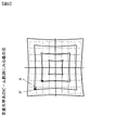
前記高エネルギービームを走査したり、画像を照射するときには、一般的には光学レンズやミラーからなる光学系や電磁コイルを用いた電子レンズを使用する。一般に、ビームを平面上に走査するときには、レーザビームならミラーの回転角度の制御、電子ビームなら電磁強度により偏向角度の制御を行う。このように、一般的には、ビーム走査は角度制御されて行われる。図1に示すように、平面に照射される時の単位角度に相当する平面上の単位長さは、走査角により異なってくる。すなわち、角度制御されたビームによる単位走査長は、光軸と成す走査角が大きいほど大きくなる。図2は、走査原理による平面に走査されたビームの軌跡を模式的に示したものである。図2において、例えばCADデータでA点にあるべき点が、走査光学系の歪によってA’点になる。この現象は、レーザビームであるか電子ビームであるかにかかわらず、高エネルギービームを、ある中心点からビームを走査する際に、必ず発生する。このように、走査型光学系には、走査歪が存在することになる。 When scanning the high-energy beam or irradiating an image, generally, an optical system including an optical lens or a mirror or an electronic lens using an electromagnetic coil is used. In general, when scanning a beam on a plane, the rotation angle of a mirror is controlled for a laser beam, and the deflection angle is controlled by an electromagnetic intensity for an electron beam. Thus, in general, beam scanning is performed with angle control. As shown in FIG. 1, the unit length on the plane corresponding to the unit angle when the plane is irradiated varies depending on the scanning angle. That is, the unit scanning length by the angle-controlled beam increases as the scanning angle formed with the optical axis increases. FIG. 2 schematically shows the trajectory of a beam scanned on a plane according to the scanning principle. In FIG. 2, for example, a point that should be at point A in the CAD data becomes point A 'due to distortion of the scanning optical system. This phenomenon always occurs when a high-energy beam is scanned from a certain center point regardless of whether it is a laser beam or an electron beam. Thus, scanning distortion exists in the scanning optical system.
更に、光学系を構成する光学部品は光軸が存在し、光学系を構成する時には全ての光軸が一致するように組み立てられる。しかしながら、光軸が完全に一致することは容易なことではなく、また、保守時の部品交換時に光軸を合うように調整することも容易ではない。その結果、光学系の光軸ズレに起因し、図3に示す模式図の軌跡のような歪も存在する。 Further, the optical components constituting the optical system have an optical axis, and are assembled so that all the optical axes coincide when the optical system is constructed. However, it is not easy for the optical axes to be completely matched, and it is not easy to adjust the optical axes so that they match when parts are replaced during maintenance. As a result, due to the optical axis shift of the optical system, there is also a distortion such as the locus of the schematic diagram shown in FIG.
前記のように、走査歪(収差)と光軸ズレによる歪が合成された光学系を用いた造形装置で生成される造形物は、造形物が置かれた位置毎に異なる歪量を有し、期待される形状の造形物を製作することは困難になる。 As described above, the modeled object generated by the modeling apparatus using the optical system in which the distortion caused by the scanning distortion (aberration) and the optical axis deviation has a different amount of distortion at each position where the modeled object is placed. It becomes difficult to produce a shaped object with the expected shape.
本発明は、このような背景のもとになされたものであり、第1の目的は、パウダーベッド方式において行われる高エネルギービームを用いた3次元造形方法において、高エネルギービームを制御する光学系が有している走査歪あるいは光軸ズレに起因する歪みを、造形物の造形前に測定し、造形データにフィードバックすることにより補正する手段を提供することであり、第2の目的は、ズレ量を造形データに補正する手段を提供することである。 The present invention has been made based on such a background, and a first object thereof is an optical system for controlling a high energy beam in a three-dimensional modeling method using a high energy beam performed in a powder bed system. The second object is to provide a means for correcting the distortion caused by the scanning distortion or the optical axis deviation possessed by the measuring object before shaping the shaped object and feeding it back to the shaping data. It is to provide a means for correcting the quantity into modeling data.
本発明は、前記課題を解決するために、次のような手段を採る。なお後述する発明を実施するための形態の説明及び図面で使用した符号を参考のために括弧書きで付記するが、本発明の構成要素は該付記したものには限定されない。 The present invention adopts the following means in order to solve the above problems. Note that the reference numerals used in the description and drawings of the embodiments for carrying out the invention to be described later are added in parentheses for reference, but the constituent elements of the present invention are not limited to those added.
まず請求項1に係る発明は、
電子ビーム又はレーザビームの高エネルギービーム(1)をエネルギー源として用い、造形しようとする一つ以上の造形物の3次元CADデータ(2)をレイアウトして作成された造形データ(3)に従って前記高エネルギービームを2次元に走査し収束する光学系(5)と、
前記高エネルギービームが収束する面(7)であって昇降機構(8)の上面に載せられ、パウダー(10)を保持するスタートプレート(9)とを備え、
前記パウダーを前記スタートプレートに撒きレーキ(11)で平坦に均した後に前記高エネルギービームを2次元に走査して該パウダーを溶融することにより層を形成し、該形成される層を前記昇降機構を下降させて重ねることにより前記造形物の造形を行う3次元造形方法であって、
前記スタートプレート上に置かれたスケールプレート(12)に前記高エネルギービームで中心点(13)を描いた後に、互いに直行する方向に前記高エネルギービームを等間隔で走査し、前記スケールプレートを取り出して、該高エネルギービームの軌跡(14)と前記中心点との距離からズレ量を測定し、該ズレ量に基づいて前記造形データを補正した後に、該補正後の造形データに基づいて前記造形物の造形を行うことにより、当該造形物の寸法を補正することを特徴とする3次元造形方法である。
First, the invention according to
According to modeling data (3) created by laying out three-dimensional CAD data (2) of one or more modeling objects to be modeled using a high energy beam (1) of an electron beam or a laser beam as an energy source An optical system (5) that scans and converges a high-energy beam in two dimensions;
A start plate (9) for holding the powder (10), which is a surface (7) on which the high energy beam converges and is placed on the upper surface of the lifting mechanism (8);
The powder is spread on the start plate and leveled with a rake (11), and then the high energy beam is scanned two-dimensionally to melt the powder to form a layer. A three-dimensional modeling method for modeling the modeled object by lowering and stacking
After the center point (13) is drawn with the high energy beam on the scale plate (12) placed on the start plate, the high energy beam is scanned at equal intervals in a direction perpendicular to each other, and the scale plate is taken out. Then, after measuring the amount of deviation from the distance between the locus (14) of the high energy beam and the center point and correcting the modeling data based on the amount of deviation, the modeling is performed based on the corrected modeling data. It is a three-dimensional modeling method characterized by correcting the dimension of the modeled object by modeling the modeled object.
また請求項2に係る発明は、
電子ビーム又はレーザビームの高エネルギービーム(1)をエネルギー源として用い、造形しようとする一つ以上の造形物の3次元CADデータ(2)をレイアウトして作成された造形データ(3)に従って前記高エネルギービームを2次元に走査し収束する光学系(5)と、
前記高エネルギービームが収束する面(7)であって昇降機構(8)の上面に載せられ、パウダー(10)を保持するスタートプレート(9)とを備え、
前記パウダーを前記スタートプレートに撒きレーキ(11)で平坦に均した後に前記高エネルギービームを2次元に走査して該パウダーを溶融することにより層を形成し、該形成される層を前記昇降機構を下降させて重ねることにより前記造形物の造形を行う3次元造形方法であって、
前記造形データに基づいて試験造形物(15)を造形し、前記試験造形物を取り出して、該試験造形物の形状からズレ量を測定し、該ズレ量に基づいて前記造形データを補正した後に、該補正後の造形データに基づいて前記造形物の造形を行うことにより、当該造形物の寸法を補正することを特徴とする3次元造形方法である。
The invention according to
According to modeling data (3) created by laying out three-dimensional CAD data (2) of one or more modeling objects to be modeled using a high energy beam (1) of an electron beam or a laser beam as an energy source An optical system (5) that scans and converges a high-energy beam in two dimensions;
A start plate (9) for holding the powder (10), which is a surface (7) on which the high energy beam converges and is placed on the upper surface of the lifting mechanism (8);
The powder is spread on the start plate and leveled with a rake (11), and then the high energy beam is scanned two-dimensionally to melt the powder to form a layer. A three-dimensional modeling method for modeling the modeled object by lowering and stacking
After modeling the test model (15) based on the model data, taking out the test model, measuring the amount of deviation from the shape of the test model, and correcting the model data based on the amount of deviation The three-dimensional modeling method is characterized by correcting the dimension of the modeled object by modeling the modeled object based on the corrected modeling data.
また請求項3に係る発明は、
請求項1又は2に記載した3次元造形方法であって、
前記ズレ量に基づく前記造形データの補正を、該造形データが示す前記造形物の輪郭の位置に対して行うことを特徴とする3次元造形方法である。
The invention according to
A three-dimensional modeling method according to
The three-dimensional modeling method is characterized in that correction of the modeling data based on the deviation amount is performed on the position of the contour of the modeled object indicated by the modeling data.
また請求項4に係る発明は、
請求項1に記載した3次元造形方法であって、
前記高エネルギービームにより前記スケールプレート上に描かれた一の軌跡と他の軌跡の間における前記造形データの補正は、前記軌跡同士の直近の交点からの補間法により算出することを特徴とする3次元造形方法である。
The invention according to
The three-dimensional modeling method according to
The correction of the modeling data between one trajectory drawn on the scale plate by the high energy beam and another trajectory is calculated by an interpolation method from the closest intersection of the
また請求項5に係る発明は、
請求項1に記載した3次元造形方法であって、
前記高エネルギービームにより前記スケールプレート上に描かれた軌跡の座標値を3次元スキャナーを用いて読み取り、真値とのズレ量を算出して、該ズレ量に基づいて前記造形データを補正することを特徴とする3次元造形方法である。
The invention according to
The three-dimensional modeling method according to
The coordinate value of the locus drawn on the scale plate by the high energy beam is read using a three-dimensional scanner, the amount of deviation from the true value is calculated, and the modeling data is corrected based on the amount of deviation. Is a three-dimensional modeling method.
また請求項6に係る発明は、
請求項2に記載した3次元造形方法であって、
前期試験造形物の形状を3次元スキャナーを用いて読み取り、前記3次元CADデータとの差異をズレ量として検出して、該ズレ量に基づいて前記造形データを補正することを特徴とする3次元造形方法である。
The invention according to
The three-dimensional modeling method according to
A three-dimensional structure characterized in that the shape of the test model is read using a three-dimensional scanner, a difference from the three-dimensional CAD data is detected as a shift amount, and the modeling data is corrected based on the shift amount. It is a modeling method.
まず請求項1に係る3次元造形方法によれば、スタートプレート上に置かれたスケールプレートに走査角ゼロ付近で互いに直行するよう高エネルギービームを走査しその交点を求める(中心点と呼ぶ)。次に2次元データに基づき一定量の間隔で供される全角度でビームを走査し収束されたビームの軌跡を描く。この軌跡を測定し、設計上の軌跡との差異、すなわちズレ量を測定し、そのズレ量を2次元の造形データに補正する。そして造形開始にあたり、高エネルギービームから出射されたビームが3次元CADデータからSTLデータに変換された後、2次元の造形データに変換されたデータに従って照射される際に、上記のように補正された造形データにより光学レンズ系あるいは電子レンズ系によりスタートプレート上のパウダーに走査し収束される。その結果、造形された生成物の形状は歪のないものとなる。 First, according to the three-dimensional modeling method according to the first aspect, high-energy beams are scanned on the scale plate placed on the start plate so as to be orthogonal to each other in the vicinity of a scanning angle of zero, and the intersection point is obtained (referred to as a center point). Next, based on the two-dimensional data, the beam is scanned at all angles provided at constant intervals, and the locus of the converged beam is drawn. This trajectory is measured, a difference from the design trajectory, that is, a deviation amount is measured, and the deviation amount is corrected to two-dimensional modeling data. At the start of modeling, the beam emitted from the high energy beam is converted from the three-dimensional CAD data to the STL data, and then irradiated according to the data converted into the two-dimensional modeling data. According to the modeling data, the powder on the start plate is scanned and converged by the optical lens system or the electronic lens system. As a result, the shape of the shaped product is not distorted.
また請求項2に係る3次元造形方法によれば、3次元CADデータから変換された造形データに基づき造形物を造形し、その造形物を3次元スキャナーで測定して3次元CADデータと比較して、各部位での差分を算出し座標各点での補正値を求めて造形データに補正する。そして造形開始にあたり、高エネルギービームから出射されたビームが3次元CADデータからSTLデータに変換された後、2次元の造形データに変換されたデータに従って照射される際に、上記のように補正された造形データにより光学レンズ系あるいは電子レンズ系によりスタートプレート上のパウダーに走査し収束される。その結果、造形された生成物の形状は歪のないものとなる。
Further, according to the 3D modeling method according to
また請求項3に係る3次元造形方法によれば、スタートプレート上には前記中心点を中心として造形物を配置した場合、一般的に中心から離れる程前記ズレ量が大きくなる傾向があるので、造形物の配置により実際の造形物には歪みが生じるし、造形物が複数個の場合にも配置される位置によりズレ量が異なるので、前記造形データの造形物の輪郭の位置データにズレ量を補正することにより、正しい寸法の造形を可能にする。
Further, according to the three-dimensional modeling method according to
また請求項4に係る3次元造形方法によれば、造形データは一般的に一定間隔で描かれるスケールプレートの軌跡上にないことが多いので、このような場合には造形データの該当点に直近のスケールプレート上軌跡の交点2点のズレ量からの補間値を用い連続的にズレ量の補正を行うことができる。 Further, according to the three-dimensional modeling method according to the fourth aspect, the modeling data is generally not on the scale plate trace drawn at regular intervals. In such a case, the modeling data is closest to the corresponding point of the modeling data. The amount of deviation can be continuously corrected using an interpolation value from the amount of deviation at the two intersections of the locus on the scale plate.
また請求項5に係る3次元造形方法によれば、スケールプレート上に描かれた軌跡を3次元スキャナーを用いて計測しその結果とスケールの真値とを比較して差異を算出しズレ量を補正することができる。
According to the three-dimensional modeling method of
また請求項6に係る3次元造形方法によれば、造形データを用いて造形した造形物を3次元スキャナーを用いて計測し各箇所での造形データとの差を計測しズレ量を補正することができる。
According to the three-dimensional modeling method according to
従来のように、造形物の製作精度が低いと 機械加工代を多くとる必要があり、結果として機械加工の削り量が増えるが、本発明により、造形物の制作精度が高くなれば、機械加工代は少なくなり、加工コストを引き下げることができる。特にTi合金のように難加工材料で造形する場合には、効果は顕著である。 If the manufacturing accuracy of the shaped object is low as in the conventional case, it is necessary to take a large machining allowance. As a result, the amount of machining is increased. The cost is reduced and the processing cost can be reduced. The effect is particularly remarkable when modeling with difficult-to-process materials such as Ti alloys.
本発明は、パウダーベッド方式における、電子ビーム又はレーザビームの高エネルギービームをエネルギー源とする3次元造形装置における光線あるいは電子線を制御する光学系が有している収差を、スケールプレートへ描画した軌跡を測定するかあるいはCADデータに基いて造形した造形物を測定することによって得られたデータと設計データを比較測定し、各部分でのズレ量を算出して、この値を基に造形データへの補正値を求め補正することが可能な3次元造形方法と、スタートプレート上に配置された一つ以上の造形物の各層の輪郭の位置でのズレ量を造形データに補正する3次元造形方法と、スケールプレート上の軌跡の位置と一致しない造形データの位置データがある場合にはスケールプレート軌跡の直近の2点との補間を行う3次元造形法と、スケールデータに基づいて描かれたスケールプレートの軌跡を3次元スキャナーを用いて測定しスケールデータとの差異を測定しズレ量を算出し補正する3次元造形法と、スケールプレートの代わりに3次元CADデータに基づいて造形した造形物を3次元スキャナーで測定し3次元CADデータとの差異を算出し造形データを補正する3次元造形法に関する。 According to the present invention, the aberration of the optical system for controlling the light beam or electron beam in the three-dimensional modeling apparatus using the high energy beam of the electron beam or laser beam as the energy source in the powder bed system is drawn on the scale plate. The design data is compared with the data obtained by measuring the trajectory or measuring the modeled object based on CAD data, and the amount of deviation in each part is calculated. Based on this value, the model data 3D modeling method capable of obtaining and correcting the correction value, and 3D modeling that corrects the amount of deviation at the position of the contour of each layer of one or more modeling objects arranged on the start plate into modeling data If there is position data of modeling data that does not match the position of the path on the scale plate, interpolation is performed between the two points closest to the scale plate path. 3D modeling method, 3D modeling method that measures the difference between the scale data by measuring the trajectory of the scale plate drawn based on the scale data using a 3D scanner, calculates the amount of deviation, and corrects the scale plate The present invention relates to a three-dimensional modeling method for measuring a modeled object modeled based on three-dimensional CAD data with a three-dimensional scanner, calculating a difference from the three-dimensional CAD data, and correcting the model data.
以下、本発明の実施の形態について、図面を参照して詳細に説明する。高エネルギービームを2次元平面に走査する時には、一般にビームを角度制御する方法を採る。図1にその概要を示しており、ビームの振れ角θをn等分したΔθを単位角として制御すると、平面スクリーンに投影される線分像のn番目の高さΔhnは
Δhn=S(tanθn-tanθn-1), ここでΔh1=StanΔθ1, θn-θn-1=Δθn=Δθ1=Δθ
1番目とn番目の線分像の比率は、次式のようになる。
Δhn/Δh1=1+tan nΔθ ・tan(n-1) Δθ
すなわち、等角度で走査したビームは振れ角によって線分像の寸法が異なっている。
図2はこのような走査時の歪を示す模式図で、データでAにあるべき点は走査時には点A’になる。データが示す点線に対し他の軌跡も太線のようになる。
Hereinafter, embodiments of the present invention will be described in detail with reference to the drawings. When scanning a high-energy beam in a two-dimensional plane, a method of controlling the angle of the beam is generally used. FIG. 1 shows an outline thereof. When Δθ obtained by dividing a beam deflection angle θ into n equal parts is used as a unit angle, the n-th height Δhn of the line segment image projected on the flat screen is Δhn = S (tan θn -tanθn-1), where Δh1 = StanΔθ1, θn-θn-1 = Δθn = Δθ1 = Δθ
The ratio of the first and nth line segment images is as follows:
Δhn / Δh1 = 1 + tan nΔθ ・ tan (n-1) Δθ
That is, the dimensions of the line segment images of beams scanned at an equal angle differ depending on the deflection angle.
FIG. 2 is a schematic diagram showing such distortion at the time of scanning, and the point that should be at A in the data is the point A ′ at the time of scanning. Other trajectories also become thick lines with respect to the dotted lines indicated by the data.
更に、高エネルギービームを制御する時に用いられる光学系に光軸が存在し、この光軸に沿って光学部品は設置される。当然、各光学部品はビームが光軸に沿って進むように配置されるが、必ずしも理想的な状態が保たれているわけではない。製作誤差や組立時のずれ、あるいは保守時に発生するずれが原因である。その結果、操作されたビームの軌跡は図3に示す一例のように歪んだものとなる。この歪みはそれぞれの光学系の状態により固有のものとなり、図1で示すような数式で表すことは困難である。 Furthermore, an optical axis exists in an optical system used when controlling a high energy beam, and optical components are installed along this optical axis. Naturally, each optical component is arranged so that the beam travels along the optical axis, but the ideal state is not always maintained. This is due to manufacturing errors, deviations during assembly, or deviations that occur during maintenance. As a result, the trajectory of the manipulated beam is distorted as in the example shown in FIG. This distortion becomes unique depending on the state of each optical system, and it is difficult to express it by a mathematical expression as shown in FIG.
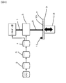
図4は、このような光学系を用いたパウダーベッド方式を用いた3次元造形装置の模式図であり、本特許の説明にあたってはビームの歪に着目した機能について示している。図4において、3次元CADデータ2はSTLデータに変換され、造形物の配置を含め実際に造形するための層毎の2次元の造形データ3に変換される。この造形データ3にしたがって、制御系4がエネルギー源と光学系5に信号を送り、エネルギー出力、走査の位置、速度、焦点等の制御を行う。エネルギー源から出射された高エネルギービーム1は、光学系5で位置、走査、焦点等をコントロールされたビーム6となり、ビーム収束面7に照射される。図には示していないパウダー収納箱から供給されレーキ11でスタートプレート9上に均一に撒かれたパウダー10がビーム収束面7にあり、選択的加熱、溶融等の加工を受ける。一層の過程が終わると昇降機構8が一ステップ下がり、パウダーが撒かれ次の層の加工を行う。この繰り返し加工により3次元造形がなされる。
FIG. 4 is a schematic diagram of a three-dimensional modeling apparatus using a powder bed system using such an optical system. In the description of this patent, a function focusing on beam distortion is shown. In FIG. 4, the three-
しかしながら、前記の工程で制作される造形物は、図2あるいは図3で示した形状の歪んだものであり、大きな製作誤差となっている。前記欠点を解決する方法の一つとして、図5に示す方法を採る。図4で説明した構成において、パウダー10の代わりにスケールプレート12の上面をビーム収束面7に合わせて設置し、ビーム6を光軸上に合わせ、ビーム6を走査して縦横に直線を描く。この縦線と横線の交点13が光軸の中心である。その後、縦及び横軸に単位間隔で横及び縦にビーム6を走査して直線を描くと図6のような太線の軌跡14を得る。この軌跡の位置データを、XY軸に高精度の位置測定機能をもった顕微鏡のような測定器を用いて読み取る。この時、図6において、入力データ点P(xn,yn)は実際には点P’(x’n,y’n)に照射されることになるため、点P(xn,yn)と点P’(x’n,y’n)の差分Δ(xn,yn)を造形データに補正することにより正しい位置点P(xn,yn)に照射することができる。3次元造形装置においては、常に2次元での造形を繰り返しおこなうので、前記の補正を各層に行えば望んだ形状の造形物を得ることができる。
However, the modeled object produced in the above process has a distorted shape shown in FIG. 2 or FIG. As one of the methods for solving the above drawbacks, the method shown in FIG. 5 is adopted. In the configuration described with reference to FIG. 4, instead of the
前記の点P(xn,yn)のように軌跡が交わった点以外の点の場合の補正値は、該当点の周辺の軌跡データから加重平均で求めることができる。 The correction value in the case of a point other than the point where the locus intersects like the point P (xn, yn) can be obtained from the locus data around the point by a weighted average.
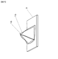
本発明の他の実施形態について説明する。図7において、15は、前記の補正を行わずにスタートプレート9上に造形した試験造形物を示しており、点線で示したピラミッド16は、正しく造形された場合の造形物を示している。このように歪んだ造形物を座標の基準点を明確にして3次元スキャナーを用いて計測し、その形状データと造形データを比較することにより造形データへの補正値を得ることができる。
Another embodiment of the present invention will be described. In FIG. 7,
1…高エネルギービーム(電子ビーム又はレーザビーム)
2…3次元CADデータ(STLデータ)
3…造形データ
4…制御系
5…光学系
6…ビーム
7…ビーム収束面
8…昇降機構
9…スタートプレート
10…パウダー
11…レーキ
12…スケールプレート
13…光軸の中心
14…ビームの軌跡
15…試験造形物
16…ピラミッド
1. High energy beam (electron beam or laser beam)
2 ... 3D CAD data (STL data)
DESCRIPTION OF
Claims (6)
前記高エネルギービームが収束する面であって昇降機構の上面に載せられ、パウダーを保持するスタートプレートとを備え、
前記パウダーを前記スタートプレートに撒きレーキで平坦に均した後に前記高エネルギービームを2次元に走査して該パウダーを溶融することにより層を形成し、該形成される層を前記昇降機構を下降させて重ねることにより前記造形物の造形を行う3次元造形方法であって、
前記スタートプレート上に置かれたスケールプレートに前記高エネルギービームで中心点を描いた後に、互いに直行する方向に前記高エネルギービームを等間隔で走査し、前記スケールプレートを取り出して、該高エネルギービームの軌跡と前記中心点との距離からズレ量を測定し、該ズレ量に基づいて前記造形データを補正した後に、該補正後の造形データに基づいて前記造形物の造形を行うことにより、当該造形物の寸法を補正することを特徴とする3次元造形方法。 Using a high-energy beam of an electron beam or a laser beam as an energy source, the high-energy beam is scanned two-dimensionally according to modeling data created by laying out three-dimensional CAD data of one or more objects to be modeled. A converging optical system;
The high energy beam is a surface on which the high energy beam converges and is placed on the upper surface of the lifting mechanism, and includes a start plate that holds powder,
The powder is sprinkled on the start plate and leveled flat by rake, and then the high energy beam is scanned two-dimensionally to melt the powder to form a layer, and the lift mechanism is moved down the formed layer. A three-dimensional modeling method for modeling the modeled object by stacking,
After drawing a center point with the high energy beam on the scale plate placed on the start plate, the high energy beam is scanned at equal intervals in a direction perpendicular to each other, the scale plate is taken out, and the high energy beam By measuring the amount of deviation from the distance between the locus and the center point, correcting the modeling data based on the amount of deviation, and then modeling the modeled object based on the modeling data after the correction, A three-dimensional modeling method comprising correcting a dimension of a modeled object.
前記高エネルギービームが収束する面であって昇降機構の上面に載せられ、パウダーを保持するスタートプレートとを備え、
前記パウダーを前記スタートプレートに撒きレーキで平坦に均した後に前記高エネルギービームを2次元に走査して該パウダーを溶融することにより層を形成し、該形成される層を前記昇降機構を上下させて重ねることにより前記造形物の造形を行う3次元造形方法であって、
前記造形データに基づいて試験造形物を造形し、前記試験造形物を取り出して、該試験造形物の形状からズレ量を測定し、該ズレ量に基づいて前記造形データを補正した後に、該補正後の造形データに基づいて前記造形物の造形を行うことにより、当該造形物の寸法を補正することを特徴とする3次元造形方法。 Using a high-energy beam of an electron beam or a laser beam as an energy source, the high-energy beam is scanned two-dimensionally according to modeling data created by laying out three-dimensional CAD data of one or more objects to be modeled. A converging optical system;
The high energy beam is a surface on which the high energy beam converges and is placed on the upper surface of the lifting mechanism, and includes a start plate that holds powder,
The powder is spread on the start plate and leveled flatly by rake, and then the high energy beam is scanned two-dimensionally to melt the powder to form a layer, and the lift mechanism is moved up and down the formed layer. A three-dimensional modeling method for modeling the modeled object by stacking,
After shaping the test model based on the model data, taking out the test model, measuring the amount of deviation from the shape of the test model, and correcting the model data based on the amount of deviation, the correction A three-dimensional modeling method characterized by correcting the dimension of the modeled object by modeling the modeled object based on subsequent modeling data.
前記ズレ量に基づく前記造形データの補正を、該造形データが示す前記造形物の輪郭の位置に対して行うことを特徴とする3次元造形方法。 A three-dimensional modeling method according to claim 1 or 2,
The three-dimensional modeling method characterized by performing correction of the modeling data based on the deviation amount with respect to the position of the contour of the modeled object indicated by the modeling data.
前記高エネルギービームにより前記スケールプレート上に描かれた一の軌跡と他の軌跡の間における前記造形データの補正は、前記軌跡同士の直近の交点からの補間法により算出することを特徴とする3次元造形方法。 The three-dimensional modeling method according to claim 1,
The correction of the modeling data between one trajectory drawn on the scale plate by the high energy beam and another trajectory is calculated by an interpolation method from the closest intersection of the trajectories 3 Dimensional modeling method.
前記高エネルギービームにより前記スケールプレート上に描かれた軌跡の座標値を3次元スキャナーを用いて読み取り、真値とのズレ量を算出して、該ズレ量に基づいて前記造形データを補正することを特徴とする3次元造形方法。 The three-dimensional modeling method according to claim 1,
The coordinate value of the locus drawn on the scale plate by the high energy beam is read using a three-dimensional scanner, the amount of deviation from the true value is calculated, and the modeling data is corrected based on the amount of deviation. 3D modeling method characterized by
前期試験造形物の形状を3次元スキャナーを用いて読み取り、前記3次元CADデータとの差異をズレ量として検出して、該ズレ量に基づいて前記造形データを補正することを特徴とする3次元造形方法。 The three-dimensional modeling method according to claim 2,
A three-dimensional structure characterized in that the shape of the test model is read using a three-dimensional scanner, a difference from the three-dimensional CAD data is detected as a shift amount, and the modeling data is corrected based on the shift amount. Modeling method.
Priority Applications (1)
| Application Number | Priority Date | Filing Date | Title |
|---|---|---|---|
| JP2015233627A JP2017100309A (en) | 2015-11-30 | 2015-11-30 | Three-dimensional molding method |
Applications Claiming Priority (1)
| Application Number | Priority Date | Filing Date | Title |
|---|---|---|---|
| JP2015233627A JP2017100309A (en) | 2015-11-30 | 2015-11-30 | Three-dimensional molding method |
Publications (1)
| Publication Number | Publication Date |
|---|---|
| JP2017100309A true JP2017100309A (en) | 2017-06-08 |
Family
ID=59017649
Family Applications (1)
| Application Number | Title | Priority Date | Filing Date |
|---|---|---|---|
| JP2015233627A Pending JP2017100309A (en) | 2015-11-30 | 2015-11-30 | Three-dimensional molding method |
Country Status (1)
| Country | Link |
|---|---|
| JP (1) | JP2017100309A (en) |
Cited By (2)
| Publication number | Priority date | Publication date | Assignee | Title |
|---|---|---|---|---|
| JP2021509935A (en) * | 2018-02-15 | 2021-04-08 | エスエルエム ソルーションズ グループ アーゲー | Equipment and methods for calibrating the irradiation system of instruments for manufacturing 3D workpieces |
| US10990079B2 (en) | 2018-03-07 | 2021-04-27 | Ricoh Company, Ltd | Fabricating apparatus, fabricating system, and fabricating method |
Citations (4)
| Publication number | Priority date | Publication date | Assignee | Title |
|---|---|---|---|---|
| JP2979431B2 (en) * | 1994-10-18 | 1999-11-15 | イーオーエス ゲゼルシャフト ミット ベシュレンクテル ハフツング イレクトロ オプティカル システムズ | Method and apparatus for calibrating a controller for deflecting a laser beam |
| JP2000233451A (en) * | 1999-02-16 | 2000-08-29 | Hyper Photon System:Kk | Calibrating device for stereo lithographic equipment |
| JP2002103459A (en) * | 2000-09-29 | 2002-04-09 | Sanyo Electric Co Ltd | Stereo lithographic device and method for producing stereo lithographic product |
| JP2002210835A (en) * | 2001-01-24 | 2002-07-31 | Matsushita Electric Works Ltd | Method for controlling deflection of laser beam and optical shaping apparatus |
-
2015
- 2015-11-30 JP JP2015233627A patent/JP2017100309A/en active Pending
Patent Citations (4)
| Publication number | Priority date | Publication date | Assignee | Title |
|---|---|---|---|---|
| JP2979431B2 (en) * | 1994-10-18 | 1999-11-15 | イーオーエス ゲゼルシャフト ミット ベシュレンクテル ハフツング イレクトロ オプティカル システムズ | Method and apparatus for calibrating a controller for deflecting a laser beam |
| JP2000233451A (en) * | 1999-02-16 | 2000-08-29 | Hyper Photon System:Kk | Calibrating device for stereo lithographic equipment |
| JP2002103459A (en) * | 2000-09-29 | 2002-04-09 | Sanyo Electric Co Ltd | Stereo lithographic device and method for producing stereo lithographic product |
| JP2002210835A (en) * | 2001-01-24 | 2002-07-31 | Matsushita Electric Works Ltd | Method for controlling deflection of laser beam and optical shaping apparatus |
Cited By (2)
| Publication number | Priority date | Publication date | Assignee | Title |
|---|---|---|---|---|
| JP2021509935A (en) * | 2018-02-15 | 2021-04-08 | エスエルエム ソルーションズ グループ アーゲー | Equipment and methods for calibrating the irradiation system of instruments for manufacturing 3D workpieces |
| US10990079B2 (en) | 2018-03-07 | 2021-04-27 | Ricoh Company, Ltd | Fabricating apparatus, fabricating system, and fabricating method |
Similar Documents
| Publication | Publication Date | Title |
|---|---|---|
| EP3224025B1 (en) | Apparatus for producing an object by means of additive manufacturing and method for calibrating an apparatus | |
| US10946581B2 (en) | Method for calibrating an apparatus for manufacturing a three-dimensional object | |
| EP3199327B1 (en) | Novel method for calibrating laser additive manufacturing process | |
| JP7190489B2 (en) | Scanning system calibration | |
| KR101590774B1 (en) | A head module for 3D printer comprising polygon mirrors rotating in single direction, and a scanning method therewith and a 3D printer therewith | |
| US11338522B2 (en) | Method for calibrating an apparatus for producing an object by means of additive manufacturing | |
| JP2009142866A5 (en) | ||
| CN105945283B (en) | Mobile powder bed type electron beam quick forming fabri-cation method | |
| JP6872922B2 (en) | Three-dimensional laminated modeling equipment | |
| US10502701B2 (en) | Method and system using x-ray pinhole camera for in-situ monitoring of electron beam manufacturing process | |
| CN110997286A (en) | Optimized partitioning method | |
| US20210122117A1 (en) | Device and method for the generative production of a three-dimensional object | |
| Jigang et al. | Two dimensional laser galvanometer scanning technology for additive manufacturing | |
| KR101697530B1 (en) | A head module for 3D printer comprising polygon mirrors rotating in single direction with a function of controlling energy density of beam, and a scanning method therewith and a 3D printer therewith | |
| JP2010089438A (en) | Method for forming slice image and shaping device | |
| CN109158600A (en) | The device and method of synchronous powder feeding system laser gain material manufacture hot spot and amyloid plaque relative position Auto-matching | |
| JP2017100309A (en) | Three-dimensional molding method | |
| JP3779358B2 (en) | Solid shape modeling method | |
| JP6283539B2 (en) | Three-dimensional additive manufacturing apparatus and three-dimensional additive manufacturing method | |
| CN103464891B (en) | Laser processing device and laser processing | |
| CN111983896A (en) | High-precision alignment method for 3D exposure machine | |
| JP2000043148A (en) | Light shaping method and device therefor | |
| JP6415004B2 (en) | Additive manufacturing equipment | |
| EP3626437A1 (en) | Method for calibrating an apparatus for additively manufacturing threedimensional objects | |
| KR102186303B1 (en) | Real-Time Automatic Height Tracer Control System Using Image Processing and Method Thereof |
Legal Events
| Date | Code | Title | Description |
|---|---|---|---|
| A621 | Written request for application examination |
Free format text: JAPANESE INTERMEDIATE CODE: A621 Effective date: 20180122 |
|
| A977 | Report on retrieval |
Free format text: JAPANESE INTERMEDIATE CODE: A971007 Effective date: 20181017 |
|
| A131 | Notification of reasons for refusal |
Free format text: JAPANESE INTERMEDIATE CODE: A131 Effective date: 20181023 |
|
| A02 | Decision of refusal |
Free format text: JAPANESE INTERMEDIATE CODE: A02 Effective date: 20190423 |