JP2017073623A - Atomic oscillator - Google Patents

Atomic oscillator Download PDF

Info

Publication number
JP2017073623A
JP2017073623A JP2015198261A JP2015198261A JP2017073623A JP 2017073623 A JP2017073623 A JP 2017073623A JP 2015198261 A JP2015198261 A JP 2015198261A JP 2015198261 A JP2015198261 A JP 2015198261A JP 2017073623 A JP2017073623 A JP 2017073623A
Authority
JP
Japan
Prior art keywords
gas cell
heat
heat transfer
unit
atomic oscillator
Prior art date
Legal status (The legal status is an assumption and is not a legal conclusion. Google has not performed a legal analysis and makes no representation as to the accuracy of the status listed.)
Withdrawn
Application number
JP2015198261A
Other languages
Japanese (ja)
Other versions
JP2017073623A5 (en
Inventor
幸治 珎道
Koji Chindo
幸治 珎道
Current Assignee (The listed assignees may be inaccurate. Google has not performed a legal analysis and makes no representation or warranty as to the accuracy of the list.)
Seiko Epson Corp
Original Assignee
Seiko Epson Corp
Priority date (The priority date is an assumption and is not a legal conclusion. Google has not performed a legal analysis and makes no representation as to the accuracy of the date listed.)
Filing date
Publication date
Application filed by Seiko Epson Corp filed Critical Seiko Epson Corp
Priority to JP2015198261A priority Critical patent/JP2017073623A/en
Priority to US15/283,742 priority patent/US9912339B2/en
Publication of JP2017073623A publication Critical patent/JP2017073623A/en
Priority to US15/877,775 priority patent/US20180152194A1/en
Publication of JP2017073623A5 publication Critical patent/JP2017073623A5/ja
Withdrawn legal-status Critical Current

Links

Images

Classifications

    • HELECTRICITY
    • H03ELECTRONIC CIRCUITRY
    • H03LAUTOMATIC CONTROL, STARTING, SYNCHRONISATION, OR STABILISATION OF GENERATORS OF ELECTRONIC OSCILLATIONS OR PULSES
    • H03L7/00Automatic control of frequency or phase; Synchronisation
    • H03L7/26Automatic control of frequency or phase; Synchronisation using energy levels of molecules, atoms, or subatomic particles as a frequency reference
    • GPHYSICS
    • G04HOROLOGY
    • G04FTIME-INTERVAL MEASURING
    • G04F5/00Apparatus for producing preselected time intervals for use as timing standards
    • G04F5/14Apparatus for producing preselected time intervals for use as timing standards using atomic clocks
    • HELECTRICITY
    • H01ELECTRIC ELEMENTS
    • H01SDEVICES USING THE PROCESS OF LIGHT AMPLIFICATION BY STIMULATED EMISSION OF RADIATION [LASER] TO AMPLIFY OR GENERATE LIGHT; DEVICES USING STIMULATED EMISSION OF ELECTROMAGNETIC RADIATION IN WAVE RANGES OTHER THAN OPTICAL
    • H01S1/00Masers, i.e. devices using stimulated emission of electromagnetic radiation in the microwave range
    • H01S1/06Gaseous, i.e. beam masers
    • HELECTRICITY
    • H03ELECTRONIC CIRCUITRY
    • H03BGENERATION OF OSCILLATIONS, DIRECTLY OR BY FREQUENCY-CHANGING, BY CIRCUITS EMPLOYING ACTIVE ELEMENTS WHICH OPERATE IN A NON-SWITCHING MANNER; GENERATION OF NOISE BY SUCH CIRCUITS
    • H03B17/00Generation of oscillations using radiation source and detector, e.g. with interposed variable obturator

Abstract

PROBLEM TO BE SOLVED: To provide an atomic oscillator having high operation stability in which impairment of a gas cell is prevented even if the dimensions vary, without compromising the heat transmission efficiency from a heating part to the gas cell.SOLUTION: An atomic oscillator includes a gas cell in which metal atoms are encapsulated, a heating part for heating the gas cell, a heat transmission part located between the gas cell and heating part, connected thermally with the gas cell, and transmitting heat generated from the heating part to the gas cell, and a heat sink connected thermally with the gas cell while separated from the heat transmission part, and absorbing heat of gas cell. The heat transmission part includes a thermally conductive elastic member held in a gap formed by a gas cell housing section including at least a pair of gas cell housing walls arranged on the outside of the gas cell, and the gas cell housing wall of the heat transmission part.SELECTED DRAWING: Figure 5

Description

本発明は、原子発振器に関するものである。   The present invention relates to an atomic oscillator.

長期的に高精度な発振特性を有する発振器として、ルビジウム、セシウム等のアルカリ金属の原子のエネルギー遷移に基づいて発振する原子発振器が知られている。一般に、原子発振器の動作原理は、光およびマイクロ波による二重共鳴現象を利用した方式と、波長の異なる2種類の光による量子干渉効果(CPT:Coherent Population Trapping)を利用した方式とに大別される。   As an oscillator having long-term highly accurate oscillation characteristics, an atomic oscillator that oscillates based on energy transition of an alkali metal atom such as rubidium or cesium is known. In general, the operating principle of an atomic oscillator is broadly divided into a method using a double resonance phenomenon by light and microwave and a method using a quantum interference effect (CPT: Coherent Population Trapping) by two types of light having different wavelengths. Is done.

いずれの方式の原子発振器においても、アルカリ金属をガスセル内に緩衝ガスとともに封入し、そのアルカリ金属をガス状に保つために、ガスセルをヒーターにより所定温度に加熱する必要がある。ここで、一般に、ガスセル内のアルカリ金属は、そのすべてがガス化するのではなく、一部が余剰分として液体となる。このような余剰分のアルカリ金属原子は、ガスセルの温度の低い部分に析出(結露)することにより液体となるが、励起光の通過領域に存在すると、励起光を遮ってしまい、その結果、原子発振器の発振特性の低下を招くこととなる。   In any type of atomic oscillator, it is necessary to heat the gas cell to a predetermined temperature with a heater in order to enclose the alkali metal together with a buffer gas in the gas cell and keep the alkali metal in a gaseous state. Here, in general, all of the alkali metal in the gas cell is not gasified, but a part thereof becomes liquid as a surplus. Such surplus alkali metal atoms become liquid by being deposited (condensation) in the low temperature part of the gas cell, but if they exist in the excitation light passage region, they block the excitation light, and as a result The oscillation characteristics of the oscillator are degraded.

そこで、特許文献1に係るガスセルでは、アルカリ金属を析出させるための凹部が励起光の光軸からずれた位置に設けられている。そして、ヒーターでガスセルの凹部から離間した部分を加熱することで、凹部の温度を周辺部よりも低下した状態とする。これにより、アルカリ金属の余剰分は液体として凹部に貯留され、余剰分が励起光を遮るのを防止している。   Therefore, in the gas cell according to Patent Document 1, a recess for depositing alkali metal is provided at a position shifted from the optical axis of the excitation light. And the part spaced apart from the recessed part of the gas cell with a heater is made into the state which lowered the temperature of the recessed part rather than the peripheral part. Thereby, the surplus of the alkali metal is stored as a liquid in the recess, and the surplus prevents the excitation light from being blocked.

しかしながら、特許文献1に記載の原子発振器を小型化した場合、その大きさによっては、ヒーターから発生した熱が原子発振器の全体に伝達されることとなる。このため、凹部の温度まで上昇してしまう。その結果、アルカリ金属の余剰分が液体として凹部に貯留されず、余剰分が励起光を遮る可能性がある。このように、小型化された原子発振器のガスセルの温度を部分的に変化させるのは困難である。   However, when the atomic oscillator described in Patent Document 1 is reduced in size, depending on the size, heat generated from the heater is transmitted to the entire atomic oscillator. For this reason, it will rise to the temperature of a recessed part. As a result, the surplus of the alkali metal is not stored in the recess as a liquid, and the surplus may block the excitation light. Thus, it is difficult to partially change the temperature of the gas cell of the miniaturized atomic oscillator.

特許文献2には、原子発振器に備えられる量子干渉装置が開示されている。特許部文献2に開示された量子干渉装置は、加熱部から供給される熱をガスセルに伝達する加熱部と、ガスセルに低温部を形成させる放熱部と、を備えることで、アルカリ金属の余剰分が励起光の通過経路に結露することを防止することがでる。従って、信頼性の高い量子干渉装置を得ることができるとしている。   Patent Document 2 discloses a quantum interference device provided in an atomic oscillator. The quantum interference device disclosed in Patent Literature 2 includes a heating unit that transmits heat supplied from the heating unit to the gas cell, and a heat dissipation unit that forms a low-temperature part in the gas cell, thereby surplus alkali metal. Can be prevented from condensing in the path of excitation light. Therefore, it is said that a highly reliable quantum interference device can be obtained.

特開2007−324818号公報JP 2007-324818 A 特開2015−122597号公報Japanese Patent Laying-Open No. 2015-122597

特許文献2に記載の量子干渉装置では、ガスセルに接続される加熱部、あるいは放熱部は、ガスセルとの接続部が密着していることで、熱移動(熱伝達)が行われる。しかし、周知の通り、部品製作には、いわゆる「寸法バラツキ」が発生する。この寸法バラツキによって、ガスセルと加熱部、あるいはガスセルと放熱部、との間の隙間にもばらつきが生じてしまう。例えば、隙間が大きくなると、隙間にある空気層が断熱層となって、ガスセルの加熱、あるいは放熱の効率を著しく低下させることとなる。特に、加熱部において熱伝達の効率が低下することによって、ガスセルの温度が不安定となり、信頼性の低い量子干渉装置となってしまう。あるいは、隙間ではなく互いの部品が重なり合い、干渉し合うような状態となると、ガラス製のガスセルに大きな負荷が掛り、ガスセルを損傷、もしくは破壊させてしまう虞があった。   In the quantum interference device described in Patent Document 2, the heating unit or the heat radiating unit connected to the gas cell performs heat transfer (heat transfer) because the connection unit with the gas cell is in close contact. However, as is well known, so-called “dimensional variation” occurs in the production of parts. Due to this dimensional variation, the gap between the gas cell and the heating part or between the gas cell and the heat dissipation part also varies. For example, when the gap becomes large, the air layer in the gap becomes a heat insulating layer, and the efficiency of heating or radiating the gas cell is significantly reduced. In particular, when the efficiency of heat transfer in the heating unit is reduced, the temperature of the gas cell becomes unstable, resulting in a quantum interference device with low reliability. Alternatively, when the components overlap each other and interfere with each other instead of the gap, a large load is applied to the glass gas cell, which may damage or destroy the gas cell.

そこで、本発明の目的は、寸法バラツキがあってもガスセルの損傷を防止し、且つ、加熱部からのガスセルへの熱伝達の効率を損なわず、高い動作安定性を備える原子発振器を提供する。   Accordingly, an object of the present invention is to provide an atomic oscillator that prevents damage to a gas cell even if there is a dimensional variation, and has high operational stability without impairing the efficiency of heat transfer from a heating unit to the gas cell.

本発明は、上述の課題の少なくとも一部を解決するためになされたものであり、以下の形態または適用例として実現することが可能である。   SUMMARY An advantage of some aspects of the invention is to solve at least a part of the problems described above, and the invention can be implemented as the following forms or application examples.

〔適用例1〕本適用例の原子発振器は、金属原子が封入されているガスセルと、前記ガスセルを加熱する加熱部と、前記ガスセルと前記加熱部との間に位置し、前記ガスセルに熱的に接続され、前記加熱部から発生する熱を前記ガスセルに伝達する伝熱部と、前記伝熱部と離間して前記ガスセルに熱的に接続され、前記ガスセルの熱を吸熱する吸熱部と、を備えている原子発振器であって、前記ガスセルの外側に配置されるガスセル収納壁を備えるガスセル収納部を有し、前記ガスセルと、前記加熱部の前記ガスセル収納壁と、によって形成される間隙に挟持される熱伝導性弾性部材を備えていることを特徴とする。   Application Example 1 An atomic oscillator of this application example is located between a gas cell in which metal atoms are sealed, a heating unit that heats the gas cell, and the gas cell and the heating unit, and is thermally connected to the gas cell. A heat transfer unit that transfers heat generated from the heating unit to the gas cell, a heat transfer unit that is thermally connected to the gas cell apart from the heat transfer unit, and absorbs heat of the gas cell; An atomic oscillator including a gas cell storage portion including a gas cell storage wall disposed outside the gas cell, and a gap formed by the gas cell and the gas cell storage wall of the heating portion. It is characterized by comprising a thermally conductive elastic member to be sandwiched.

本適用例の原子発振器によれば、小型化されたガスセルであっても、周辺部よりも温度が低い低温度部を効果的に形成することができる。よって、低温度部に金属原子を結露させ、余剰分を液体として貯留することができる。このように、余剰分を容易に制御することができるため、余剰分が励起光の光路を遮るのを容易に防止することができ、よって、量子干渉装置の信頼性を高めることができる。   According to the atomic oscillator of this application example, even in a downsized gas cell, it is possible to effectively form a low temperature part having a temperature lower than that of the peripheral part. Therefore, metal atoms can be condensed in the low temperature part, and the surplus can be stored as a liquid. Thus, since the surplus can be easily controlled, it is possible to easily prevent the surplus from blocking the optical path of the excitation light, and thus the reliability of the quantum interference device can be improved.

更に、ガスセルの小型化は、ガスセルを構成する材料の薄型化となり、ガスセル収納壁とガスセルの製造バラツキによる部品干渉が原因とするガスセル損傷を回避させるために、伝熱部のガスセル収納壁と、ガスセルと、の間に隙間を設ける必要があった。しかし、ガスセル収納壁と、ガスセルと、の間の隙間は、空気などの気体が存在する領域となって、ガスセル収納壁からガスセルへの熱伝達性を低下させる。そこで、ガスセル収納壁と、ガスセルと、の間の隙間に、熱伝導性弾性部材を配設させることにより、ガスセル収納壁からガスセルへの熱伝達経路を確保し、更に、熱伝導性弾性部材の弾性によって、ガスセル収納壁間にガスセルを安定して固定させることができる。   Furthermore, the downsizing of the gas cell results in a thinner material constituting the gas cell, and in order to avoid gas cell damage caused by component interference due to manufacturing variations of the gas cell storage wall and the gas cell, It was necessary to provide a gap between the gas cell and the gas cell. However, the gap between the gas cell storage wall and the gas cell becomes a region where a gas such as air exists, and reduces heat transfer from the gas cell storage wall to the gas cell. Therefore, by arranging the heat conductive elastic member in the gap between the gas cell storage wall and the gas cell, a heat transfer path from the gas cell storage wall to the gas cell is secured, and further, the heat conductive elastic member Due to the elasticity, the gas cells can be stably fixed between the gas cell storage walls.

〔適用例2〕上述の適用例において、前記熱伝導性弾性部材は、ゴム系の接着剤、パッキン、もしくはシート片であることを特徴とする。   Application Example 2 In the application example described above, the heat conductive elastic member is a rubber adhesive, packing, or a sheet piece.

上述の適用例によれば、ガスセル収納壁内にガスセルを配設した後に、ガスセル収納壁と、ガスセルと、の間に生じる隙間に熱伝導性弾性部材を容易に配設することができる。   According to the above application example, after the gas cell is disposed in the gas cell storage wall, the heat conductive elastic member can be easily disposed in the gap formed between the gas cell storage wall and the gas cell.

〔適用例3〕上述の適用例において、前記熱伝導弾性部材は、ゴム系充填剤であることを特徴とする。   Application Example 3 In the application example described above, the heat conducting elastic member is a rubber filler.

上述の適用例によれば、ガスセル収納壁内にガスセルを配設した後に、ガスセル収納壁と、ガスセルと、の間に生じる隙間にばらつきが生じても、充填可能な熱伝導性弾性部材をその隙間に充填することで、容易に配設することができる。   According to the application example described above, even after the gas cell is arranged in the gas cell storage wall, even if the gap generated between the gas cell storage wall and the gas cell varies, the heat conductive elastic member that can be filled is It can arrange | position easily by filling a clearance gap.

〔適用例4〕上述の適用例において、前記ガスセル内を透過する磁場を発生させるコイルを備え、前記ガスセルと、前記伝熱部と、前記吸熱部と、前記コイルと、を内部に収納する磁気遮蔽体を備え、前記伝熱部と、前記吸熱部と、が前記磁気遮蔽体と熱的に接続され、前記加熱部は、前記磁気遮蔽体の外部と熱的に接続されていることを特徴とする。   Application Example 4 In the application example described above, a magnet is provided that generates a magnetic field that passes through the gas cell, and the gas cell, the heat transfer unit, the heat absorption unit, and the coil are accommodated therein. It is provided with a shield, wherein the heat transfer part and the heat absorption part are thermally connected to the magnetic shield, and the heating part is thermally connected to the outside of the magnetic shield. And

上述の適用例によれば、コイルに通電することにより、ガスセル内を透過する磁場を発生させ、ガスセル内に存在するアルカリ金属の原子の縮退している異なるエネルギー準位間のギャップをゼーマン分裂によって拡げて分解能を向上させ、EIT(電磁誘起透明化現象:Electromagnetically Induced Transparency)信号の線幅を小さくすることができる。コイルから発生される磁場を安定させるために、コイル以外の、外部からの磁力線のガスセルへの侵入を防止するため、磁気遮蔽体を備える。   According to the application example described above, by energizing the coil, a magnetic field that passes through the gas cell is generated, and gaps between different energy levels of degenerated alkali metal atoms present in the gas cell are generated by Zeeman splitting. The resolution can be improved by widening and the line width of an EIT (Electromagnetically Induced Transparency) signal can be reduced. In order to stabilize the magnetic field generated from the coil, a magnetic shield is provided to prevent intrusion of magnetic lines of force from outside the coil into the gas cell.

また、外気と繋がる磁気遮蔽体に加熱部、伝熱部および吸熱部が熱的に接続されることにより、加熱部で生じさせた熱を、加熱部と磁気遮蔽体との接続部から磁気遮蔽体の形状に沿って広い範囲へ拡散させ、より多くの熱を伝熱部へ伝達させることができる。一方、吸熱部を磁気遮蔽体と熱的に接続させることにより、磁気遮蔽体に広い外気への放熱領域を形成させることができ、吸熱部に伝達された熱を効率的に放熱させることができる。   In addition, the heating unit, heat transfer unit, and heat absorption unit are thermally connected to the magnetic shield connected to the outside air, so that the heat generated in the heating unit is shielded from the connection between the heating unit and the magnetic shield. It is possible to diffuse more heat along the body shape and transfer more heat to the heat transfer section. On the other hand, by thermally connecting the heat absorption part with the magnetic shield, it is possible to form a wide heat dissipation area for the outside air in the magnetic shield, and to efficiently dissipate the heat transmitted to the heat absorption part. .

第1実施形態に係る原子発振器の概略構成を示す模式図。The schematic diagram which shows schematic structure of the atomic oscillator which concerns on 1st Embodiment. アルカリ金属のエネルギー状態を説明するための状態図。The state diagram for demonstrating the energy state of an alkali metal. 光射出部から出射される2つの光の周波数差と、光検出部で検出される光の強度との関係を示すグラフ。The graph which shows the relationship between the frequency difference of two light radiate | emitted from a light emission part, and the intensity | strength of the light detected by a photon detection part. 第1実施形態に係る原子発振器を模式的に示す斜視図。1 is a perspective view schematically showing an atomic oscillator according to a first embodiment. 第1実施形態に係る原子発振器が備える第2ユニットの断面図。Sectional drawing of the 2nd unit with which the atomic oscillator which concerns on 1st Embodiment is provided. 図5に示す伝熱部の斜視図。The perspective view of the heat-transfer part shown in FIG. 図5に示すA−A´部の断面図。Sectional drawing of the AA 'part shown in FIG. 図5に示す吸熱部の斜視図。FIG. 6 is a perspective view of the heat absorption unit shown in FIG. 5. 図5に示すB−B´部の断面図。Sectional drawing of the BB 'part shown in FIG. 第1実施形態に係る原子発振器に備えるガスセルの内部温度分布を説明する模式図。The schematic diagram explaining the internal temperature distribution of the gas cell with which the atomic oscillator which concerns on 1st Embodiment is equipped. 第1実施形態に係る原子発振器の伝熱部材のその他の形態を示す断面図。Sectional drawing which shows the other form of the heat-transfer member of the atomic oscillator which concerns on 1st Embodiment. 第1実施形態に係る原子発振器の伝熱部材のその他の形態を示す断面図。Sectional drawing which shows the other form of the heat-transfer member of the atomic oscillator which concerns on 1st Embodiment. 第1実施形態に係る原子発振器の伝熱部材のその他の形態を示す断面図。Sectional drawing which shows the other form of the heat-transfer member of the atomic oscillator which concerns on 1st Embodiment. 第1実施形態に係る原子発振器の伝熱部材のその他の形態を示す断面図。Sectional drawing which shows the other form of the heat-transfer member of the atomic oscillator which concerns on 1st Embodiment. 第2実施形態に係る電子機器の一例としてGPS衛星を利用した測位システムの概略構成を示す図。The figure which shows schematic structure of the positioning system using a GPS satellite as an example of the electronic device which concerns on 2nd Embodiment. 第3実施形態に係る電子機器の一例としてのクロック伝送システムを示す概略構成図。The schematic block diagram which shows the clock transmission system as an example of the electronic device which concerns on 3rd Embodiment. 第4実施形態に係る移動体の一例としての自動車の構成を示す斜視図。The perspective view which shows the structure of the motor vehicle as an example of the mobile body which concerns on 4th Embodiment.

以下、図面を参照して、本発明に係る実施形態を説明する。   Embodiments according to the present invention will be described below with reference to the drawings.

(第1実施形態)
図1は、第1実施形態に係る原子発振器の概略構成を示す構成図である。また、図2は、アルカリ金属のエネルギー状態を説明する説明図、図3は、光射出部から出射される2つの光の周波数差と、光検出部で検出される光の強度との関係を示すグラフである。
(First embodiment)
FIG. 1 is a configuration diagram showing a schematic configuration of the atomic oscillator according to the first embodiment. FIG. 2 is an explanatory diagram for explaining the energy state of the alkali metal, and FIG. 3 shows the relationship between the frequency difference between the two lights emitted from the light emitting part and the intensity of the light detected by the light detecting part. It is a graph to show.

図1に示す原子発振器100は、量子干渉効果を利用した原子発振器である。この原子発振器100は、図1に示すように、光出射側のユニットである第1ユニット200と、光検出側のユニットである第2ユニット300と、第1ユニット200および第2ユニット300を制御する制御部400と、を備える。   An atomic oscillator 100 shown in FIG. 1 is an atomic oscillator using a quantum interference effect. As shown in FIG. 1, the atomic oscillator 100 controls a first unit 200 that is a light emission side unit, a second unit 300 that is a light detection side unit, and the first unit 200 and the second unit 300. And a control unit 400.

第1ユニット200は、光射出部211と、光射出部211を収納し、光を透過する窓部213を有する第1パッケージ212とを備える光射出装置210と、光学部品群220と、を備えている。また、第2ユニット300は、ガスセル310と、光検出部320と、コイル350と、加熱部としてのヒーター330と、温度センサー340と、後述する伝熱部と、吸熱部と、これらを収納する磁気シールドと、を備える。   The first unit 200 includes a light emitting unit 211, a light emitting device 210 including the light emitting unit 211, and a first package 212 having a window 213 that transmits light, and an optical component group 220. ing. The second unit 300 houses the gas cell 310, the light detection unit 320, the coil 350, the heater 330 as a heating unit, a temperature sensor 340, a heat transfer unit, a heat absorption unit, and a heat absorption unit described later. A magnetic shield.

まず、原子発振器100の原理を簡単に説明する。図1に示すように、原子発振器100では、光射出部211がガスセル310に向けて励起光LLを出射し、ガスセル310を透過した励起光LLを光検出部320が検出する。ガスセル310内には、ガス状のアルカリ金属(金属原子)が封入されており、アルカリ金属は、図2に示すように、3準位系のエネルギー準位を有し、エネルギー準位の異なる2つの基底状態(基底状態1,2)と、励起状態との3つの状態をとり得る。ここで、基底状態1は、基底状態2よりも低いエネルギー状態である。   First, the principle of the atomic oscillator 100 will be briefly described. As shown in FIG. 1, in the atomic oscillator 100, the light emitting unit 211 emits the excitation light LL toward the gas cell 310, and the light detection unit 320 detects the excitation light LL transmitted through the gas cell 310. In the gas cell 310, gaseous alkali metal (metal atom) is sealed. As shown in FIG. 2, the alkali metal has energy levels of a three-level system, and has different energy levels. Three ground states (ground states 1 and 2) and an excited state can be taken. Here, the ground state 1 is a lower energy state than the ground state 2.

光射出部211から出射された励起光LLは、周波数の異なる2種の共鳴光1,2を含んでおり、この2種の共鳴光1,2を前述したようなガス状のアルカリ金属に照射したとき、共鳴光1の周波数ω1と共鳴光2の周波数ω2との差(ω1−ω2)に応じて、共鳴光1、2のアルカリ金属における光吸収率(光透過率)が変化する。そして、共鳴光1の周波数ω1と共鳴光2の周波数ω2との差(ω1−ω2)が基底状態1と基底状態2とのエネルギー差に相当する周波数に一致したとき、基底状態1,2から励起状態への励起がそれぞれ停止する。このとき、共鳴光1,2は、いずれも、アルカリ金属に吸収されずに透過する。このような現象をCPT現象または電磁誘起透明化現象(EIT:Electromagnetically Induced Transparency)と呼ぶ。   The excitation light LL emitted from the light emitting unit 211 includes two types of resonance lights 1 and 2 having different frequencies. The two types of resonance lights 1 and 2 are irradiated onto the gaseous alkali metal as described above. Then, the optical absorptance (light transmittance) of the resonant lights 1 and 2 in the alkali metal changes according to the difference (ω1−ω2) between the frequency ω1 of the resonant light 1 and the frequency ω2 of the resonant light 2. When the difference (ω1−ω2) between the frequency ω1 of the resonant light 1 and the frequency ω2 of the resonant light 2 matches the frequency corresponding to the energy difference between the ground state 1 and the ground state 2, the ground states 1 and 2 Each excitation to the excited state stops. At this time, both the resonant lights 1 and 2 are transmitted without being absorbed by the alkali metal. Such a phenomenon is referred to as a CPT phenomenon or an electromagnetically induced transparency (EIT: Electromagnetically Induced Transparency).

例えば、光射出部211が共鳴光1の周波数ω1を固定し、共鳴光2の周波数ω2を変化させていくと、共鳴光1の周波数ω1と共鳴光2の周波数ω2との差(ω1−ω2)が基底状態1と基底状態2とのエネルギー差に相当する周波数ω0に一致したとき、光検出部320の検出強度は、図3に示すように、急峻に上昇する。このような急峻な信号をEIT信号として検出する。このEIT信号は、アルカリ金属の種類によって決まった固有値をもっている。したがって、このようなEIT信号を用いることにより、発振器を構成することができる。   For example, when the light emitting unit 211 fixes the frequency ω1 of the resonant light 1 and changes the frequency ω2 of the resonant light 2, the difference between the frequency ω1 of the resonant light 1 and the frequency ω2 of the resonant light 2 (ω1-ω2). ) Matches the frequency ω 0 corresponding to the energy difference between the ground state 1 and the ground state 2, the detection intensity of the light detection unit 320 increases sharply as shown in FIG. Such a steep signal is detected as an EIT signal. This EIT signal has an eigenvalue determined by the type of alkali metal. Therefore, an oscillator can be configured by using such an EIT signal.

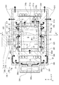
以下、本実施形態の原子発振器100の具体的な構成について説明する。図4は、図1に示す原子発振器100を模式的に示す斜視図、図5は、図1に示す原子発振器100が備える第2ユニット300の断面図である。図5では、説明の便宜上、互いに直交する3つの軸として、X軸、Y軸およびZ軸を図示しており、その図示された各矢印の先端側を「+(プラス)」、基端側を「−(マイナス)」という。また、以下では、説明の便宜上、X軸に沿った方向を「X軸方向」、Y軸に沿った方向を「Y軸方向」、Z軸に沿った方向を「Z軸方向」ともいう。   Hereinafter, a specific configuration of the atomic oscillator 100 of the present embodiment will be described. 4 is a perspective view schematically showing the atomic oscillator 100 shown in FIG. 1, and FIG. 5 is a cross-sectional view of the second unit 300 included in the atomic oscillator 100 shown in FIG. In FIG. 5, for convenience of explanation, the X axis, the Y axis, and the Z axis are illustrated as three axes orthogonal to each other, and the distal end side of each illustrated arrow is “+ (plus)”, and the proximal end side Is called "-(minus)". Hereinafter, for convenience of explanation, the direction along the X-axis is also referred to as “X-axis direction”, the direction along the Y-axis is referred to as “Y-axis direction”, and the direction along the Z-axis is referred to as “Z-axis direction”.

原子発振器100は、図4に示すように、第1ユニット200と、第2ユニット300と、制御部400(図4には図示せず。図1参照。)と、を備える。そして、第1ユニット200および第2ユニット300は、配線およびコネクター(図示せず)介して制御部400に電気的に接続され、制御部400により駆動制御される。   As shown in FIG. 4, the atomic oscillator 100 includes a first unit 200, a second unit 300, and a control unit 400 (not shown in FIG. 4, refer to FIG. 1). The first unit 200 and the second unit 300 are electrically connected to the control unit 400 via wiring and connectors (not shown), and are driven and controlled by the control unit 400.

第1ユニット200は、光射出部211と、光射出部211を収納する第1パッケージ212と、窓部213と、を備える光射出装置210と、光学部品群220と、を備える。   The first unit 200 includes a light emitting unit 211, a light emitting device 210 that includes a first package 212 that houses the light emitting unit 211, and a window 213, and an optical component group 220.

光射出部211は、ガスセル310中のアルカリ金属原子を励起する励起光LLを出射する機能を有する。具体的には、光射出部211は、前述したような周波数の異なる2種の光(共鳴光1および共鳴光2)を含む光を励起光LLとして出射するものである。共鳴光1の周波数ω1は、ガスセル310中のアルカリ金属を前述した基底状態1から励起状態に励起(共鳴)し得るものである。また、共鳴光2の周波数ω2は、ガスセル310中のアルカリ金属を前述した基底状態2から励起状態に励起(共鳴)し得るものである。   The light emitting unit 211 has a function of emitting excitation light LL that excites alkali metal atoms in the gas cell 310. Specifically, the light emitting unit 211 emits light including two types of light (resonant light 1 and resonant light 2) having different frequencies as described above as excitation light LL. The frequency ω1 of the resonant light 1 is capable of exciting (resonating) the alkali metal in the gas cell 310 from the ground state 1 to the excited state. The frequency ω <b> 2 of the resonant light 2 can excite (resonate) the alkali metal in the gas cell 310 from the ground state 2 to the excited state.

この光射出部211としては、前述したような励起光LLを出射し得るものであれば、特に限定されないが、例えば、垂直共振器面発光レーザー(VCSEL)等の半導体レーザー等を用いることができる。また、このような光射出部211は、図示しない温度調節素子(発熱抵抗体、ペルチェ素子等)により、所定温度に温度調節される。   The light emitting unit 211 is not particularly limited as long as it can emit the excitation light LL as described above. For example, a semiconductor laser such as a vertical cavity surface emitting laser (VCSEL) can be used. . Further, such a light emitting portion 211 is temperature-controlled to a predetermined temperature by a temperature adjusting element (a heating resistor, a Peltier element, etc.) not shown.

第1パッケージ212は、前述した光射出部211を収納する。第1パッケージ212は、例えば、図4に示すように、外形形状がブロック状をなす筐体で構成されている。また、第1パッケージ212からは、例えば、複数のリード(図示せず)が突出しており、これらは、配線を介して光射出部211に電気的に接続されている。そして、各リードは、図示しないコネクター等で配線基板と電気的に接続されている。このコネクターとしては、例えば、フレキシブル基板や、ソケット状をなすもの等を用いることができる。また、第1パッケージ212の第2ユニット300側の壁部には、窓部213が設けられている。この窓部213は、ガスセル310と光射出部211との間の光軸(励起光LLの軸a)上に設けられている。そして、窓部213は、前述した励起光LLに対して透過性を有する。   The first package 212 houses the light emitting unit 211 described above. For example, as shown in FIG. 4, the first package 212 includes a housing whose outer shape forms a block shape. Further, for example, a plurality of leads (not shown) protrude from the first package 212, and these are electrically connected to the light emitting unit 211 via wiring. Each lead is electrically connected to the wiring board by a connector or the like (not shown). As this connector, for example, a flexible board or a socket-shaped one can be used. In addition, a window portion 213 is provided on the wall portion of the first package 212 on the second unit 300 side. This window part 213 is provided on the optical axis (axis a of the excitation light LL) between the gas cell 310 and the light emitting part 211. And the window part 213 has transparency with respect to the excitation light LL mentioned above.

本実施形態では、窓部213は、レンズである。これにより、励起光LLを無駄なくガスセル310へ照射することができる。また、窓部213は、励起光LLを平行光とする機能を有する。すなわち、窓部213はコリメートレンズであり、後述するガスセル310の内部空間Sにおける励起光LLは平行光である。これにより、内部空間Sに存在するアルカリ金属の原子のうち、光射出部211から出射した励起光LLにより共鳴するアルカリ金属の原子の数を多くすることができる。その結果、EIT信号の強度を高めることができる。   In the present embodiment, the window portion 213 is a lens. Thereby, the excitation light LL can be irradiated to the gas cell 310 without waste. Moreover, the window part 213 has a function which makes the excitation light LL parallel light. That is, the window part 213 is a collimating lens, and the excitation light LL in the internal space S of the gas cell 310 described later is parallel light. Thereby, among the alkali metal atoms present in the internal space S, the number of alkali metal atoms that resonate with the excitation light LL emitted from the light emitting portion 211 can be increased. As a result, the intensity of the EIT signal can be increased.

なお、窓部213は、励起光LLに対する透過性を有するものであれば、レンズに限定されず、例えば、レンズ以外の光学部品であってもよいし、単なる光透過性の板状部材であってもよい。この場合、前述したような機能を有するレンズは、例えば、後述する光学部品群220を構成する光学部品221,222,223と同様、第1パッケージ212および後述する磁気遮蔽体380との間に設けられていてもよい。このような第1パッケージ212の窓部213以外の部分の構成材料としては、特に限定されず、例えば、セラミックス、金属、樹脂等を用いることができる。   The window 213 is not limited to a lens as long as it has transparency to the excitation light LL. For example, the window 213 may be an optical component other than a lens, or may be a simple light-transmissive plate member. May be. In this case, the lens having the above-described function is provided between the first package 212 and a magnetic shield 380 described later, for example, as in the case of optical components 221, 222, and 223 constituting the optical component group 220 described later. It may be done. The constituent material of the portion other than the window portion 213 of the first package 212 is not particularly limited, and for example, ceramic, metal, resin, or the like can be used.

また、第1パッケージ212の窓部213以外の部分が励起光LLに対して透過性を有する材料で構成されている場合、第1パッケージ212の窓部213以外の部分と窓部213と一体的に形成することができる。なお、第1パッケージ212の窓部213以外の部分が励起光LLに対して透過性を有しない材料で構成されている場合、第1パッケージ212の窓部213以外の部分と窓部213とを別体で形成し、これらを公知の接合方法により接合すればよい。   Further, when a portion other than the window portion 213 of the first package 212 is made of a material that is transmissive to the excitation light LL, the portion other than the window portion 213 of the first package 212 and the window portion 213 are integrated. Can be formed. In addition, when parts other than the window part 213 of the 1st package 212 are comprised with the material which does not have the transparency with respect to the excitation light LL, parts other than the window part 213 of the 1st package 212 and the window part 213 are combined. What is necessary is just to form by another body and to join these by a well-known joining method.

また、第1パッケージ212内が気密空間であることが好ましい。これにより、第1パッケージ212内を減圧状態または不活性ガス封入状態とすることができ、その結果、原子発振器100の特性を向上させることができる。また、第1パッケージ212内には、光射出部211の温度を調節する温度調節素子や温度センサー等が収納されている(図示せず)。かかる温度調節素子としては、例えば、発熱抵抗体(ヒーター)、ペルチェ素子等が挙げられる。このような第1パッケージ212によれば、光射出部211から第1パッケージ212外への励起光LLの出射を許容しつつ、光射出部211を第1パッケージ212内に収納することができる。   Moreover, it is preferable that the inside of the first package 212 is an airtight space. Thereby, the inside of the 1st package 212 can be made into a pressure reduction state or an inert gas enclosure state, As a result, the characteristic of the atomic oscillator 100 can be improved. Further, the first package 212 houses a temperature adjusting element, a temperature sensor, and the like that adjust the temperature of the light emitting unit 211 (not shown). Examples of such temperature adjusting elements include heating resistors (heaters), Peltier elements, and the like. According to such a first package 212, the light emitting part 211 can be accommodated in the first package 212 while allowing the excitation light LL to be emitted from the light emitting part 211 to the outside of the first package 212.

第2ユニット300は、上述したガスセル310と、光検出部320と、コイル350と、伝熱部360と、吸熱部370と、を内部に収納する磁気遮蔽体380と、ヒーター330と、温度センサー340とを備える。   The second unit 300 includes a magnetic shield 380 that houses the gas cell 310, the light detection unit 320, the coil 350, the heat transfer unit 360, and the heat absorption unit 370 described above, a heater 330, and a temperature sensor. 340.

ガスセル310内には、ガス状のルビジウム、セシウム、ナトリウム等のアルカリ金属が封入されている。また、ガスセル310内には、必要に応じて、アルゴン、ネオン等の希ガス、窒素等の不活性ガスが緩衝ガスとしてアルカリ金属ガスとともに封入されていてもよい。   The gas cell 310 is filled with gaseous alkali metals such as rubidium, cesium, and sodium. Further, in the gas cell 310, a rare gas such as argon or neon, or an inert gas such as nitrogen may be enclosed as a buffer gas together with an alkali metal gas as necessary.

本実施形態に係る原子発振器100に備えるガスセル310は、図5に示すように、貫通孔311aを有する本体部311と、その貫通孔311aの両側の開口を封鎖し、励起光LLが透過可能となる透過領域を備える光透過部としての一対の窓部312、313とを有する。これにより、前述したようなアルカリ金属が封入される内部空間Sが形成されている。また、本体部311の一部は、外側に向って突出した突出部311bが形成されており、突出部311bの内側は、液だまり部311cとして機能する。この液だまり部311cは、アルカリ金属の一部が余剰分として液状で貯留される部分である。後述するように、この液だまり部311cの温度を、周辺部よりも低下させることで、液だまり部311c内にアルカリ金属の余剰分を結露させて貯留することができる。   As shown in FIG. 5, the gas cell 310 provided in the atomic oscillator 100 according to the present embodiment blocks the main body 311 having the through hole 311 a and the openings on both sides of the through hole 311 a so that the excitation light LL can be transmitted. And a pair of window portions 312 and 313 as a light transmission portion having a transmission region. Thereby, the internal space S in which the alkali metal as described above is enclosed is formed. In addition, a part of the main body 311 is formed with a protruding part 311b protruding outward, and the inside of the protruding part 311b functions as a liquid pool part 311c. The liquid pool portion 311c is a portion in which a part of the alkali metal is stored in liquid form as an excess. As will be described later, by reducing the temperature of the liquid pool portion 311c below that of the peripheral portion, excess alkali metal can be condensed in the liquid pool portion 311c and stored.

本体部311を構成する材料としては、特に限定されず、金属材料、樹脂材料、ガラス材料、シリコン材料、水晶等が挙げられるが、加工性や窓部312,313との接合の観点から、ガラス材料、シリコン材料を用いるのが好ましい。このような本体部311には、窓部312,313が気密的に接合されている。これにより、ガスセル310の内部空間Sを気密空間とすることができる。   The material constituting the main body 311 is not particularly limited, and examples thereof include a metal material, a resin material, a glass material, a silicon material, and a crystal. From the viewpoint of workability and bonding with the window portions 312 and 313, glass is used. It is preferable to use a material or a silicon material. The window portions 312 and 313 are airtightly joined to the main body portion 311. Thereby, the internal space S of the gas cell 310 can be made into an airtight space.

本体部311と窓部312,313との接合方法としては、これらの構成材料に応じて決められるものであり、特に限定されないが、例えば、接着剤による接合方法、直接接合法、陽極接合法等を用いることができる。また、窓部312,313を構成する材料としては、前述したような励起光LLに対する透過性を有していれば、特に限定されないが、本体部311との接合の観点から、例えば、シリコン材料、ガラス材料、水晶等が挙げられ、本体部311と同じ材料であることがなお好ましい。   The bonding method between the main body 311 and the windows 312 and 313 is determined according to these constituent materials and is not particularly limited. For example, a bonding method using an adhesive, a direct bonding method, an anodic bonding method, and the like. Can be used. In addition, the material constituting the windows 312 and 313 is not particularly limited as long as it has transparency to the excitation light LL as described above. From the viewpoint of bonding with the main body 311, for example, a silicon material is used. , Glass material, crystal, and the like, and the same material as the main body 311 is more preferable.

各窓部312,313は、前述した光射出装置210からの励起光LLに対する透過性を有している。そして、一方の窓部312は、ガスセル310内へ入射する励起光LLが透過するものであり、他方の窓部313は、ガスセル310内から出射した励起光LLが透過するものである。そして、ガスセル310は、ヒーター330により加熱され、所定温度に温度調節される。   Each of the window portions 312 and 313 has transparency to the excitation light LL from the light emitting device 210 described above. One window portion 312 transmits the excitation light LL incident on the gas cell 310, and the other window portion 313 transmits the excitation light LL emitted from the gas cell 310. The gas cell 310 is heated by the heater 330 and the temperature is adjusted to a predetermined temperature.

光検出部320は、ガスセル310内を透過した励起光LL(共鳴光1,2)の強度を検出する機能を有する。この光検出部320としては、上述したような励起光LLを検出し得るものであれば、特に限定されないが、例えば、太陽電池、フォトダイオード等の光検出器(受光素子)を用いることができる。また、光検出部320は、本実施形態では、磁気遮蔽体380内に収納されているが、磁気遮蔽体380の外側に設けられていてもよい。この場合、磁気遮蔽体380には、ガスセル310を通過した励起光LLが通過する窓部が形成されている。   The light detection unit 320 has a function of detecting the intensity of the excitation light LL (resonance light 1 and 2) transmitted through the gas cell 310. The photodetector 320 is not particularly limited as long as it can detect the excitation light LL as described above. For example, a photodetector (light receiving element) such as a solar cell or a photodiode can be used. . Further, in the present embodiment, the light detection unit 320 is housed in the magnetic shield 380, but may be provided outside the magnetic shield 380. In this case, the magnetic shield 380 is formed with a window portion through which the excitation light LL that has passed through the gas cell 310 passes.

コイル350は、通電により、内部空間Sに励起光LLの光軸aに沿った方向の磁場を発生させ、内部空間Sに存在するアルカリ金属の原子の縮退している異なるエネルギー準位間のギャップをゼーマン分裂によって拡げて分解能を向上させ、EIT信号の線幅を小さくすることができる。なお、コイル350が発生する磁場は、直流磁場または交流磁場のいずれかの磁場であってもよく、直流磁場と交流磁場とを重畳させた磁場であってもよい。コイル350としては、特に限定されず、例えば、ソレノイド型を構成するようにガスセル310の外周に沿って巻回して設けられていてもよいし、ヘルムホルツ型を構成するように1対のコイルをガスセル310を介して対向させてもよい。本実施形態では、コイル350は、ソレノイド型で構成され、伝熱部360、ガスセル310および吸熱部370の外側に巻かれている。このコイル350は、図示しない配線を介して、後述する制御部400の磁場制御部430に電気的に接続され、コイル350に通電が行なわれている。   The coil 350, when energized, generates a magnetic field in the direction along the optical axis a of the excitation light LL in the internal space S, and gaps between different energy levels in which the alkali metal atoms present in the internal space S are degenerated. Can be expanded by Zeeman splitting to improve resolution and reduce the line width of the EIT signal. The magnetic field generated by the coil 350 may be either a DC magnetic field or an AC magnetic field, or may be a magnetic field in which a DC magnetic field and an AC magnetic field are superimposed. The coil 350 is not particularly limited. For example, the coil 350 may be provided by being wound around the outer periphery of the gas cell 310 so as to constitute a solenoid type, or a pair of coils may be provided as a gas cell so as to constitute a Helmholtz type. You may oppose via 310. In the present embodiment, the coil 350 is configured as a solenoid type and is wound around the heat transfer unit 360, the gas cell 310, and the heat absorption unit 370. The coil 350 is electrically connected to a magnetic field control unit 430 of the control unit 400 described later via a wiring (not shown), and the coil 350 is energized.

磁気遮蔽体380は、外形形状がブロック状をなす筐体で構成されており、内部にコイル350、伝熱部360、ガスセル310および吸熱部370を収納する。この磁気遮蔽体380は、磁気シールド性を有し、ガスセル310を外部磁界から遮蔽する機能を有している。これにより、磁気遮蔽体380内でコイル350が発生する磁場を安定させることができる。よって、原子発振器100の発振特性の向上を図ることができる。   The magnetic shield 380 is configured by a housing whose outer shape is a block shape, and houses the coil 350, the heat transfer unit 360, the gas cell 310, and the heat absorption unit 370 therein. The magnetic shield 380 has a magnetic shielding property and has a function of shielding the gas cell 310 from an external magnetic field. Thereby, the magnetic field generated by the coil 350 in the magnetic shield 380 can be stabilized. Therefore, the oscillation characteristics of the atomic oscillator 100 can be improved.

また、磁気遮蔽体380の第1ユニット200側の壁部には、その厚さ方向に貫通する窓部380aが設けられ、光射出装置210から出射した励起光LLが窓部380aを介してガスセル310内に入射される。なお、磁気遮蔽体380の構成材料としては、磁気シールド性を有する材料が用いられ、例えば、Fe、各種鉄系合金(ケイ素鉄、パーマロイ、アモルファス、センダスト、コバール)等の軟磁性材料が挙げられ、中でも、磁気シールド性が優れるという観点から、コバール、パーマロイ等のFe−Ni系合金を用いることが好ましい。また、磁気遮蔽体380からは、光検出部320、ヒーター330、温度センサー340(図示せず)およびコイル350に電気的に接続されている複数のリード(図示せず)が突出しており、これら複数のリードは、配線を介して図示しないコネクター等で配線基板と電気的に接続されている。このコネクターとしては、例えば、フレキシブル基板や、ソケット状をなすもの等を用いることができる。   Further, the wall portion on the first unit 200 side of the magnetic shield 380 is provided with a window portion 380a penetrating in the thickness direction, and the excitation light LL emitted from the light emitting device 210 passes through the window portion 380a to the gas cell. Incident in 310. As a constituent material of the magnetic shield 380, a material having magnetic shielding properties is used, and examples thereof include soft magnetic materials such as Fe and various iron alloys (silicon iron, permalloy, amorphous, sendust, kovar). Among these, from the viewpoint of excellent magnetic shielding properties, it is preferable to use an Fe—Ni alloy such as Kovar or Permalloy. Further, from the magnetic shield 380, a plurality of leads (not shown) electrically connected to the light detection unit 320, the heater 330, the temperature sensor 340 (not shown), and the coil 350 protrude. The plurality of leads are electrically connected to the wiring board via connectors and the like (not shown). As this connector, for example, a flexible board or a socket-shaped one can be used.

ヒーター330は、前述したガスセル310内に気密封止されているアルカリ金属を加熱する機能を有する。これにより、ガスセル310中のアルカリ金属を所望濃度のガス状に維持することができる。ヒーター330は、通電により発熱するものであり、例えば、ガスセル310の外表面上に設けられた発熱抵抗体で構成されている。このような発熱抵抗体は、例えば、プラズマCVD、熱CVDのような化学蒸着法(CVD)、真空蒸着等の乾式メッキ法、ゾル・ゲル法等を用いて形成される。なお、発熱抵抗体が、ガスセル310の励起光LLの入射部側または出射部側に設けられる場合には、励起光LLに対する透過性を有する材料、例えば、ITO(Indium Tin Oxide)、IZO(Indium Zinc Oxide)、In33、SnO2、Sb含有SnO2、Al含有ZnO等の酸化物等の透明電極材料で構成される。 The heater 330 has a function of heating the alkali metal hermetically sealed in the gas cell 310 described above. Thereby, the alkali metal in the gas cell 310 can be maintained in a gaseous state with a desired concentration. The heater 330 generates heat when energized. For example, the heater 330 includes a heating resistor provided on the outer surface of the gas cell 310. Such a heating resistor is formed using, for example, a chemical vapor deposition method (CVD) such as plasma CVD or thermal CVD, a dry plating method such as vacuum deposition, a sol-gel method, or the like. In addition, when the heating resistor is provided on the incident part side or the emission part side of the excitation light LL of the gas cell 310, a material having transparency to the excitation light LL, for example, ITO (Indium Tin Oxide), IZO (Indium) Zinc Oxide), In 3 O 3 , SnO 2 , Sb-containing SnO 2 , and transparent electrode materials such as oxides such as Al-containing ZnO.

また、ヒーター330は、磁気遮蔽体380の外側に、磁気遮蔽体380より熱伝導率が高い伝熱板390を介して磁気遮蔽体380に接続されている。前述したように、ヒーター330は、通電により発熱するため、発熱した際、磁場が生じる。しかし、ヒーター330は、磁気遮蔽体380の外側に設けることにより、ヒーター330から生じる磁場の磁気遮蔽体380内への侵入を防止しすることができ、コイル350から発生される磁場への影響を抑制することができる。   Further, the heater 330 is connected to the magnetic shield 380 via a heat transfer plate 390 having a higher thermal conductivity than the magnetic shield 380 outside the magnetic shield 380. As described above, since the heater 330 generates heat when energized, a magnetic field is generated when the heater 330 generates heat. However, by providing the heater 330 outside the magnetic shield 380, the magnetic field generated from the heater 330 can be prevented from entering the magnetic shield 380, and the influence on the magnetic field generated from the coil 350 can be prevented. Can be suppressed.

なお、ヒーター330は、ガスセル310を加熱することができるものであれば、特に限定されず、ガスセル310に対して非接触であってもよい。また、ヒーター330に代えて、または、ヒーター330と併用して、ペルチェ素子を用いて、ガスセル310を加熱してもよい。このようなヒーター330は、後述する制御部400の温度制御部420に電気的に接続され、通電制御される。   The heater 330 is not particularly limited as long as it can heat the gas cell 310, and may be non-contact with the gas cell 310. Further, the gas cell 310 may be heated using a Peltier element instead of the heater 330 or in combination with the heater 330. Such a heater 330 is electrically connected to a temperature control unit 420 of the control unit 400, which will be described later, and is energized.

図5には図示されないが、原子発振器100は温度センサー340を備えている。温度センサー340は、ヒーター330またはガスセル310の温度を検出するものである。そして、この温度センサー340の検出結果に基づいて、温度制御部420(図1参照)によってヒーター330への通電量が制御され、ヒーター330の温度が制御される。そして、ガスセル310が所望の温度に維持され、ガスセル310内のアルカリ金属原子を所望の温度に維持することができる。なお、温度センサー340の設置位置は、特に限定されず、例えば、ヒーター330上であってもよいし、ガスセル310の外表面上であってもよい。温度センサー340としては特に限定されず、サーミスタ、熱電対等の公知の各種温度センサーを用いることができる。   Although not shown in FIG. 5, the atomic oscillator 100 includes a temperature sensor 340. The temperature sensor 340 detects the temperature of the heater 330 or the gas cell 310. Then, based on the detection result of the temperature sensor 340, the temperature control unit 420 (see FIG. 1) controls the amount of energization to the heater 330, and the temperature of the heater 330 is controlled. Then, the gas cell 310 is maintained at a desired temperature, and the alkali metal atoms in the gas cell 310 can be maintained at the desired temperature. The installation position of the temperature sensor 340 is not particularly limited, and may be on the heater 330 or on the outer surface of the gas cell 310, for example. The temperature sensor 340 is not particularly limited, and various known temperature sensors such as a thermistor and a thermocouple can be used.

第1ユニット200は、複数の光学部品221,222,223によって構成される光学部品群220を備えている。光学部品群220は、第1パッケージ212内の光射出部211と、ガスセル310との間に、励起光LLの光軸a上に設けられている。   The first unit 200 includes an optical component group 220 including a plurality of optical components 221, 222, and 223. The optical component group 220 is provided on the optical axis a of the excitation light LL between the light emitting unit 211 in the first package 212 and the gas cell 310.

本実施形態の光学部品群220は、光射出部211からガスセル310に向かって、光学部品221、光学部品222、光学部品223の順に配置されている。光学部品221は、λ/4波長板である。これにより、例えば、光射出部211からの線偏光である励起光LLを円偏光(右円偏光または左円偏光)に変換することができる。   The optical component group 220 of this embodiment is arranged in the order of the optical component 221, the optical component 222, and the optical component 223 from the light emitting unit 211 toward the gas cell 310. The optical component 221 is a λ / 4 wavelength plate. Thereby, for example, the excitation light LL that is linearly polarized light from the light emitting unit 211 can be converted into circularly polarized light (right circularly polarized light or left circularly polarized light).

前述したようにコイル350の磁場によりガスセル310内のアルカリ金属原子がゼーマン分裂した状態において、仮に直線偏光の励起光LLをアルカリ金属原子に照射すると、励起光LLとアルカリ金属原子との相互作用により、アルカリ金属原子がゼーマン分裂した複数の準位に均等に分散して存在することとなる。その結果、所望のエネルギー準位のアルカリ金属原子の数が他のエネルギー準位のアルカリ金属原子の数に対して相対的に少なくなるため、所望のEIT現象を発現する原子数が減少し、所望のEIT信号が小さくなり、その結果、原子発振器100の発振特性の低下をもたらす。   As described above, when the alkali metal atoms in the gas cell 310 are Zeeman split by the magnetic field of the coil 350 and the alkali metal atoms are irradiated with the linearly polarized excitation light LL, the interaction between the excitation light LL and the alkali metal atoms is caused. In other words, the alkali metal atoms are present evenly dispersed in a plurality of Zeeman split levels. As a result, the number of alkali metal atoms at a desired energy level is relatively small with respect to the number of alkali metal atoms at other energy levels, so that the number of atoms that develop a desired EIT phenomenon is reduced and desired. As a result, the oscillation characteristic of the atomic oscillator 100 is deteriorated.

これに対し、前述したようにコイル350の磁場によりガスセル310内のアルカリ金属原子がゼーマン分裂した状態において、円偏光の励起光LLをアルカリ金属原子に照射すると、励起光LLとアルカリ金属原子との相互作用により、アルカリ金属原子がゼーマン分裂した複数の準位のうち、所望のエネルギー準位のアルカリ金属原子の数を他のエネルギー準位のアルカリ金属原子の数に対して相対的に多くすることができる。そのため、所望のEIT現象を発現する原子数が増大し、所望のEIT信号が大きくなり、その結果、原子発振器100の発振特性を向上させることができる。   On the other hand, when the alkali metal atom is irradiated with the circularly polarized excitation light LL in the state where the alkali metal atom in the gas cell 310 is Zeeman split by the magnetic field of the coil 350 as described above, the excitation light LL and the alkali metal atom Among a plurality of levels in which an alkali metal atom is Zeeman split by interaction, the number of alkali metal atoms at a desired energy level is set to be relatively larger than the number of alkali metal atoms at other energy levels. Can do. As a result, the number of atoms that develop the desired EIT phenomenon increases, and the desired EIT signal increases. As a result, the oscillation characteristics of the atomic oscillator 100 can be improved.

なお、光学部品221の平面視形状は、特に限定されず、例えば、円形、四角形、五角形等の多角形をなしていてもよい。また、光学部品群220は、光学部品221に加えて、第2ユニット300側は、光学部品222,223が配置されている。光学部品222,223は、減光フィルター(NDフィルター)であり、ガスセル310に入射する励起光LLの強度を減少、調整することができる。従って、光射出部211の出力が大きい場合でも、ガスセル310に入射する励起光LLを所望の光量とすることができる。なお、光学部品222,223は、それぞれ、板状をなしている。また、光学部品222,223の平面視形状は、特に限定されず、例えば、円形、四角形、五角形等の多角形をなしていてもよい。また、光射出部211の出力の大きさによっては、光学部品222,223のうちのいずれか一方、あるいは両方の光学部品を省略してもよい。   In addition, the planar view shape of the optical component 221 is not particularly limited, and may be a polygon such as a circle, a quadrangle, or a pentagon. In the optical component group 220, in addition to the optical component 221, optical components 222 and 223 are arranged on the second unit 300 side. The optical components 222 and 223 are neutral density filters (ND filters), and can reduce and adjust the intensity of the excitation light LL incident on the gas cell 310. Therefore, even when the output of the light emitting unit 211 is large, the excitation light LL incident on the gas cell 310 can be set to a desired light amount. The optical components 222 and 223 each have a plate shape. Moreover, the planar view shape of the optical components 222 and 223 is not particularly limited, and may be a polygon such as a circle, a quadrangle, or a pentagon. Further, depending on the output level of the light emitting unit 211, either one of the optical components 222 and 223 or both of the optical components may be omitted.

図1に示す制御部400は、ヒーター330、コイル350および光射出部211をそれぞれ制御する機能を有する。本実施形態では、制御部400は、IC(Integrated Circuit)チップで構成されている。このような制御部400は、光射出部211の共鳴光1,2の周波数を制御する励起光制御部410と、ガスセル310中のアルカリ金属の温度を制御する温度制御部420と、ガスセル310に印加する磁場を制御する磁場制御部430とを有する。   The control unit 400 illustrated in FIG. 1 has a function of controlling the heater 330, the coil 350, and the light emitting unit 211, respectively. In the present embodiment, the control unit 400 is configured by an IC (Integrated Circuit) chip. Such a control unit 400 includes an excitation light control unit 410 that controls the frequencies of the resonance lights 1 and 2 of the light emitting unit 211, a temperature control unit 420 that controls the temperature of the alkali metal in the gas cell 310, and the gas cell 310. A magnetic field control unit 430 that controls the magnetic field to be applied.

励起光制御部410は、前述した光検出部320の検出結果に基づいて、光射出部211から出射される共鳴光1,2の周波数を制御する。より具体的には、励起光制御部410は、光検出部320の検出結果に基づいて、周波数差(ω1−ω2)がアルカリ金属固有の周波数ω0となるように、光射出部211から出射される共鳴光1,2の周波数を制御する。   The excitation light control unit 410 controls the frequencies of the resonance lights 1 and 2 emitted from the light emission unit 211 based on the detection result of the light detection unit 320 described above. More specifically, the excitation light control unit 410 is emitted from the light emitting unit 211 so that the frequency difference (ω1−ω2) becomes the frequency ω0 unique to the alkali metal based on the detection result of the light detection unit 320. The frequency of the resonant light 1 and 2 is controlled.

また、励起光制御部410は、図示しないが、電圧制御型水晶発振器(発振回路)を備えており、その電圧制御型水晶発振器の発振周波数を光検出部320の検知結果に基づいて同期・調整しながら原子発振器100の出力信号として出力する。また、温度制御部420は、温度センサー340の検出結果に基づいて、ヒーター330への通電を制御する。これにより、ガスセル310を所望の温度範囲内に維持することができる。また、磁場制御部430は、コイル350が発生する磁場が一定となるように、コイル350への通電を制御する。   Although not shown, the excitation light control unit 410 includes a voltage controlled crystal oscillator (oscillation circuit), and the oscillation frequency of the voltage controlled crystal oscillator is synchronized and adjusted based on the detection result of the light detection unit 320. While being output as an output signal of the atomic oscillator 100. Further, the temperature control unit 420 controls energization to the heater 330 based on the detection result of the temperature sensor 340. Thereby, the gas cell 310 can be maintained within a desired temperature range. The magnetic field control unit 430 controls energization to the coil 350 so that the magnetic field generated by the coil 350 is constant.

伝熱部360は、図5に示すように、ガスセル310の外側に配置されている。伝熱部360は、少なくとも磁気遮蔽体380より熱伝導率の高い材料で構成されており、ヒーター330から発生する熱を、ガスセル310に伝達する。なお、本明細書中では、各部材間で熱の移動が可能な状態を「熱的に接続」されている状態と言う。すなわち、各部材間で熱の移動が可能であれば、各部材が接触している状態であっても、非接触の状態(例えば、接着剤等を介して各部材が固定されている状態)であっても「熱的に接続」されている状態として説明する。   The heat transfer section 360 is disposed outside the gas cell 310 as shown in FIG. The heat transfer unit 360 is made of a material having a higher thermal conductivity than at least the magnetic shield 380, and transfers heat generated from the heater 330 to the gas cell 310. In the present specification, a state in which heat can be transferred between the members is referred to as a “thermally connected” state. That is, as long as heat can be transferred between the members, even if the members are in contact with each other, they are in a non-contact state (for example, each member is fixed through an adhesive or the like). Even so, it will be described as being “thermally connected”.

図6は、伝熱部360の外観斜視図である。図6に示すように、伝熱部360は、Y軸方向を厚さ方向とし、Y軸方向からみたとき四角形の板状をなす基部360aと、基部360aの縁部からY(+)方向に立設した4つのガスセル収納壁としての壁部360b,360c,360d,360eとで構成されている。壁部360bと壁部360dとは、X軸方向に対向しており、壁部360bがX(+)側に位置し、壁部360dがX(−)側に位置している。また、壁部360cと壁部360eとは、Z軸方向に対向しており、壁部360cがZ(−)側に位置し、壁部360eがZ(+)側に位置している。そして、壁部360b,360c,360d,360eの隣り合う壁部は互いに連結されており、全体として筒状をなしている。また、基部360aと各壁部360b,360c,360d,360eとで囲まれた部分は、ガスセル310の一部が挿入されるガスセル収納部としての第1凹部360fとなっている。   FIG. 6 is an external perspective view of the heat transfer section 360. As shown in FIG. 6, the heat transfer section 360 has a Y-axis direction as a thickness direction, a base 360 a that forms a square plate when viewed from the Y-axis direction, and a Y (+) direction from the edge of the base 360 a. It is comprised by the wall part 360b, 360c, 360d, and 360e as the upright four gas cell storage wall. The wall portion 360b and the wall portion 360d are opposed to each other in the X-axis direction, the wall portion 360b is located on the X (+) side, and the wall portion 360d is located on the X (−) side. The wall 360c and the wall 360e face each other in the Z-axis direction, the wall 360c is located on the Z (−) side, and the wall 360e is located on the Z (+) side. And the adjacent wall part of wall part 360b, 360c, 360d, 360e is mutually connected, and has comprised the cylinder shape as a whole. A portion surrounded by the base portion 360a and each of the wall portions 360b, 360c, 360d, and 360e is a first recess 360f that serves as a gas cell storage portion into which a part of the gas cell 310 is inserted.

また、基部360aは、Y(−)側の端部に周回するように第2凹部360gが形成されている。第2凹部360gは図5にも示すように、伝熱部360と吸熱部370との外周に巻かれているコイル350が配設される部分である。第2凹部360gにコイル350の一部を配設させることにより、原子発振器100の小型化を図ることができる。なお、本実施形態に係る伝熱部360では、壁部360b,360c,360d,360eは枠状に形成されている形態を例示するが、これに限定されない。壁部はガスセル310が収容可能であれば、壁部360b,360c,360d,360eが互いに接続されていなくてもよい。   The base 360a is formed with a second recess 360g so as to go around the end on the Y (−) side. As shown in FIG. 5, the second concave portion 360 g is a portion where a coil 350 wound around the outer periphery of the heat transfer portion 360 and the heat absorption portion 370 is disposed. By disposing a part of the coil 350 in the second recess 360g, the atomic oscillator 100 can be reduced in size. In addition, in the heat-transfer part 360 which concerns on this embodiment, although wall part 360b, 360c, 360d, 360e illustrates the form formed in frame shape, it is not limited to this. As long as the wall can accommodate the gas cell 310, the walls 360b, 360c, 360d, and 360e may not be connected to each other.

また、壁部360bには、窓部312における励起光LLの透過領域に対応した開口部としての貫通孔の窓部360hが設けられ、壁部360dには、窓部313における励起光LLの透過領域に対応した開口部としての貫通孔の窓部360jが設けられている。各窓部360h,360jは、励起光LLが通過できるよう(図5参照)、X軸方向から見て、重なっている。よって、第1凹部360f内にガスセル310を挿入した状態で、励起光LLが、窓部360h、ガスセル310の窓部312,313、窓部360jの順に通過あるいは透過し、光検出部320に励起光LLを入射させることができる。   The wall 360b is provided with a through-hole window 360h serving as an opening corresponding to the transmission region of the excitation light LL in the window 312. The wall 360d transmits the excitation light LL in the window 313. A through-hole window 360j serving as an opening corresponding to the region is provided. The window portions 360h and 360j overlap each other when viewed from the X-axis direction so that the excitation light LL can pass (see FIG. 5). Therefore, with the gas cell 310 inserted into the first recess 360f, the excitation light LL passes or passes through the window 360h, the windows 312 and 313 of the gas cell 310, and the window 360j in this order, and is excited by the light detection unit 320. Light LL can be incident.

上述した伝熱部360を介して、ヒーター330からガスセル310への熱伝達について説明する。図5に示すように、ヒーター330において発生させた熱Qは、先ず伝熱板390に伝達される。伝熱板390は、高い熱伝導率を備えていることから、伝熱板390の全体に熱Qは伝達され、伝熱板390に接続された磁気遮蔽体380のヒーター330に対向する壁部380bに向かって、伝熱板390に伝達された熱Qが伝達、移動される。   Heat transfer from the heater 330 to the gas cell 310 through the heat transfer unit 360 described above will be described. As shown in FIG. 5, the heat Q generated in the heater 330 is first transmitted to the heat transfer plate 390. Since the heat transfer plate 390 has high thermal conductivity, the heat Q is transmitted to the entire heat transfer plate 390, and the wall portion facing the heater 330 of the magnetic shield 380 connected to the heat transfer plate 390. The heat Q transmitted to the heat transfer plate 390 is transmitted and moved toward 380b.

続いて、磁気遮蔽体380の壁部380bに伝達された熱Qは、伝熱部360の基部360aのY(−)側端部から伝達される熱Q1、および基部360aの外周面から伝達される熱Q2となって伝熱部360に伝達される。基部360aに伝達された熱Q1,Q2は、伝熱部360内を伝達し、一部は各壁部360b,360c,360d,360eへ伝達、移動される。各壁部360b,360c,360d,360eに到達した熱Q1,Q2は、次のようにガスセル310に伝達される。   Subsequently, the heat Q transmitted to the wall portion 380b of the magnetic shield 380 is transmitted from the heat Q1 transmitted from the Y (−) side end portion of the base portion 360a of the heat transfer portion 360 and the outer peripheral surface of the base portion 360a. The heat Q2 is transmitted to the heat transfer section 360. The heat Q1 and Q2 transmitted to the base portion 360a is transmitted through the heat transfer portion 360, and part of the heat is transmitted and moved to the respective wall portions 360b, 360c, 360d, and 360e. The heats Q1 and Q2 that have reached the walls 360b, 360c, 360d, and 360e are transferred to the gas cell 310 as follows.

まず、基部360aから、第1凹部360f(図6参照)の底部に接続されたガスセル310の本体部311に、熱Q3として伝達される。ガスセル310に伝達された熱Q3以外の熱は、各壁部360b,360c,360d,360eに伝達され、熱Q4,Q5としてガスセル310の窓部312,313に伝達される。   First, heat Q3 is transferred from the base 360a to the main body 311 of the gas cell 310 connected to the bottom of the first recess 360f (see FIG. 6). Heat other than the heat Q3 transmitted to the gas cell 310 is transmitted to the respective walls 360b, 360c, 360d, and 360e, and is transmitted to the windows 312 and 313 of the gas cell 310 as heat Q4 and Q5.

上述したように、伝熱部360の第1凹部360fにガスセル310が挿入されている。この時、第1凹部360fの内部にガスセル310が挿入可能とするためには、製造の際のバラツキを考慮し、設計条件として第1凹部360fとガスセル310と、の間に隙間δh1を設けるようにする必要がある。仮に、設計上で隙間δh1を設けない場合、ガスセル310の外形が第1凹部360f内形より僅かでも大きく製造されると、小型化が望まれる原子発振器100では、ガスセル310自体の小型化が必須となり、その結果、ガスセル310の本体部311、あるいは窓部312,313は、より薄肉の材料から形成される。更に上述したように、本体部311、窓部312,313はガラスなどの、いわゆる脆性材料を用いていることから、わずかな応力で破損、破壊が生じ易くなってしまう。   As described above, the gas cell 310 is inserted into the first recess 360f of the heat transfer section 360. At this time, in order to allow the gas cell 310 to be inserted into the first recess 360f, a gap δh1 is provided as a design condition between the first recess 360f and the gas cell 310 in consideration of manufacturing variations. It is necessary to. If the gap δh1 is not provided in the design, if the outer shape of the gas cell 310 is manufactured to be slightly larger than the inner shape of the first recess 360f, in the atomic oscillator 100 where miniaturization is desired, the gas cell 310 itself must be downsized. As a result, the main body 311 or the windows 312 and 313 of the gas cell 310 are formed from a thinner material. Further, as described above, since the main body portion 311 and the window portions 312 and 313 are made of a so-called brittle material such as glass, they are easily damaged or broken by a slight stress.

従って、設計段階から隙間δh1を設けることが必要であった。ここでδh1は、図5に示すX軸方向の、壁部360bとガスセル310の窓部312との隙間δh11、壁部360dとガスセル310の窓部313との隙間δh12とすると、
δh1=δh11+δh12
で表され、
0≦δh11≦δh1
0≦δh12≦δh1
である。
Therefore, it is necessary to provide the gap δh1 from the design stage. Here, δh1 is a gap δh11 between the wall 360b and the window 312 of the gas cell 310 and a gap δh12 between the wall 360d and the window 313 of the gas cell 310 in the X-axis direction shown in FIG.
δh1 = δh11 + δh12
Represented by
0 ≦ δh11 ≦ δh1
0 ≦ δh12 ≦ δh1
It is.

図5に図示する熱Q4の伝達経路の場合、壁部360b,360dから隙間δh11,δh12を介してガスセル310の窓部312,313に熱Q4が伝達されることとなる。この場合、隙間δh11,δh12は、空気などのガスセル310周囲の気体環境の気体が存在している。空気の場合には、周知の通り熱伝導率は極めて低く、むしろ断熱性を備えている。従って、伝熱部360から、ガスセル310へ、熱伝達ロスを抑制させながら熱を伝達させるために、熱伝導性弾性部材としての伝熱部材511,512が隙間δh11,δh12に装着されている。   In the case of the heat Q4 transmission path shown in FIG. 5, the heat Q4 is transmitted from the walls 360b and 360d to the windows 312 and 313 of the gas cell 310 through the gaps δh11 and δh12. In this case, in the gaps δh11 and δh12, a gas in a gas environment around the gas cell 310 such as air exists. In the case of air, as is well known, the thermal conductivity is extremely low, but rather has a heat insulating property. Therefore, in order to transmit heat from the heat transfer section 360 to the gas cell 310 while suppressing heat transfer loss, heat transfer members 511 and 512 as heat conductive elastic members are mounted in the gaps δh11 and δh12.

図5に示すA−A´部の断面を図7に示す。図7に示すように、上述した隙間δh11,δh12に加えて、Z軸方向にも壁部360cとガスセル310との間に隙間δh21と、壁部360eとガスセル310との間に隙間δh22と、が設定されている。設計段階でのZ軸方向の隙間δh2とすると、
δh2=δh21+δh22
0≦δh21≦δh2
0≦δh22≦δh2
で表される。
FIG. 7 shows a cross section taken along line AA ′ shown in FIG. As shown in FIG. 7, in addition to the gaps δh11 and δh12 described above, the gap δh21 between the wall 360c and the gas cell 310 in the Z-axis direction, and the gap δh22 between the wall 360e and the gas cell 310, Is set. Assuming the gap δh2 in the Z-axis direction at the design stage,
δh2 = δh21 + δh22
0 ≦ δh21 ≦ δh2
0 ≦ δh22 ≦ δh2
It is represented by

そして、隙間δh11には伝熱部材511が、隙間δh12には伝熱部材512が、隙間δh21には伝熱部材513が、隙間δh22には伝熱部材514が、装着されている。伝熱部材511,512,513,514は弾性を有し、かつ熱伝導性を有する材料、例えばシリコンゴム、金属フィラー入りゴム、などが好適に用いられる。すなわち、伝熱部材511,512,513,514を介して各壁部360b,360c,360d,360eからガスセル310に熱を伝達させるためには、伝熱部材511,512,513,514は、各壁部360b,360c,360d,360eとガスセル310とを、密着させることで効率よく熱伝達が行える。従って、伝熱部材511,512,513,514が弾性を有することで、伝熱部材511,512,513,514が常態として各壁部360b,360c,360d,360eと、ガスセル310と、を押圧するように作用し、密着させることができる。   A heat transfer member 511 is attached to the gap δh11, a heat transfer member 512 is attached to the gap δh12, a heat transfer member 513 is attached to the gap δh21, and a heat transfer member 514 is attached to the gap δh22. For the heat transfer members 511, 512, 513, and 514, materials having elasticity and heat conductivity, for example, silicon rubber, rubber with metal filler, and the like are preferably used. That is, in order to transfer heat from each wall 360b, 360c, 360d, 360e to the gas cell 310 via the heat transfer members 511, 512, 513, 514, the heat transfer members 511, 512, 513, 514 Heat transfer can be efficiently performed by bringing the walls 360b, 360c, 360d, and 360e into close contact with the gas cell 310. Therefore, the heat transfer members 511, 512, 513, and 514 have elasticity so that the heat transfer members 511, 512, 513, and 514 normally press the walls 360b, 360c, 360d, and 360e and the gas cell 310. It can be made to adhere and adhere.

このように、伝熱部材511,512,513,514を備えることによって、図5に矢印で示す熱Q5の伝熱経路で表されるように、伝熱部材511,512,513,514を介して各壁部360b,360c,360d,360eからガスセル310に熱伝達ロスを軽減して、効率よく熱を供給することができる。   Thus, by providing the heat transfer members 511, 512, 513, and 514, the heat transfer members 511, 512, 513, and 514 are interposed as shown by the heat transfer path of the heat Q5 indicated by the arrow in FIG. Thus, heat transfer loss can be reduced from each wall 360b, 360c, 360d, 360e to the gas cell 310 to efficiently supply heat.

吸熱部370は、図5に示すように、ガスセル310の外側に配置されている。吸熱部370は、少なくとも磁気遮蔽体380より熱伝導率の高い材料で構成されており、ガスセル310における余剰熱量を、磁気遮蔽体380を介して磁気遮蔽体380の外部へ放熱する。   The heat absorption part 370 is arrange | positioned on the outer side of the gas cell 310, as shown in FIG. The heat absorbing part 370 is made of a material having a higher thermal conductivity than at least the magnetic shield 380, and dissipates excess heat in the gas cell 310 to the outside of the magnetic shield 380 via the magnetic shield 380.

図8は、吸熱部370の外観斜視図である。図8に示すように、吸熱部370は、Y軸方向を厚さ方向とし、Y軸方向からみたとき四角形の板状をなす基部370aと、基部370aの縁部からY(−)方向に立設した4つのガスセル収納壁となる壁部370b,370c,370d,370eとに分けることができる。壁部370bと壁部370dとは、Z軸方向に対向しており、壁部370bがZ(+)側に位置し、壁部370dがZ(−)側に位置している。また、壁部370cと壁部370eとは、X軸方向に対向しており、壁部370cがX(+)側に位置し、壁部370eがX(−)側に位置している。そして、壁部370b,370c,370d,370eの隣り合う壁部は互いに連結されており、全体として筒状をなしている。また、基部370aと各壁部370b,370c,370d,370eとで囲まれた部分は、ガスセル310の一部が挿入されるガスセル収納部となる第1凹部370fとなっている。なお、本実施形態に係る吸熱部370では、壁部370b,370c,370d,370eは枠状に形成されている形態を例示するが、これに限定されない。壁部はガスセル310が収容可能であれば、壁部370b,370c,370d,370eが互いに接続されていなくてもよい。   FIG. 8 is an external perspective view of the heat absorbing portion 370. As shown in FIG. 8, the endothermic portion 370 has a Y-axis direction as a thickness direction, and stands in a Y (−) direction from a base portion 370a having a rectangular plate shape when viewed from the Y-axis direction, and an edge portion of the base portion 370a. It can be divided into four wall portions 370b, 370c, 370d, and 370e that serve as four gas cell storage walls. The wall portion 370b and the wall portion 370d are opposed to each other in the Z-axis direction, the wall portion 370b is located on the Z (+) side, and the wall portion 370d is located on the Z (−) side. The wall portion 370c and the wall portion 370e face each other in the X-axis direction, the wall portion 370c is located on the X (+) side, and the wall portion 370e is located on the X (−) side. The adjacent wall portions of the wall portions 370b, 370c, 370d, and 370e are connected to each other and form a cylindrical shape as a whole. Further, a portion surrounded by the base portion 370a and each of the wall portions 370b, 370c, 370d, and 370e is a first concave portion 370f serving as a gas cell storage portion into which a part of the gas cell 310 is inserted. In addition, in the heat absorption part 370 which concerns on this embodiment, although wall part 370b, 370c, 370d, 370e illustrates the form formed in frame shape, it is not limited to this. As long as the gas cell 310 can be accommodated in the wall portion, the wall portions 370b, 370c, 370d, and 370e may not be connected to each other.

また、基部370aのY(+)側の端部にX軸に沿って、壁部370cと壁部370eとの外端部には、Y軸方向に沿って第2凹部370gが形成されている。第2凹部370gは図5にも示すように、伝熱部360と吸熱部370との外周に巻かれているコイル350が配設される部分である。第2凹部370gにコイル350の一部を配設させることにより、原子発振器100の小型化を図ることができる。   A second recess 370g is formed along the X axis at the Y (+) side end of the base 370a, and along the Y axis direction at the outer ends of the wall 370c and the wall 370e. . As shown in FIG. 5, the second recess 370 g is a portion where a coil 350 wound around the outer periphery of the heat transfer section 360 and the heat absorption section 370 is disposed. By disposing a part of the coil 350 in the second recess 370g, the atomic oscillator 100 can be reduced in size.

また、基部370aには、ガスセル310の突出部311bが挿通される貫通孔370hが形成されている。貫通孔370hに挿通される突出部311bの熱は、貫通孔370hの内周面を介して吸熱部370に伝達される。従って、吸熱部370の貫通孔370hに突出部311bが挿通されることで、突出部311bの冷却が促進され、ガスセル310内のアルカリ原子の余剰分が突出部311bの液だまり部311c内に結露しやすくなり、原子発振器100を安定して発振させることができる。なお、貫通孔370hは、第1凹部370f側に開口を有する凹部であってもよく、その場合には突出部311bと干渉しない深さを備えている。   Further, a through hole 370h through which the protruding portion 311b of the gas cell 310 is inserted is formed in the base portion 370a. The heat of the protruding portion 311b inserted through the through hole 370h is transmitted to the heat absorbing portion 370 via the inner peripheral surface of the through hole 370h. Therefore, the protrusion 311b is inserted into the through-hole 370h of the heat absorbing part 370, whereby the cooling of the protrusion 311b is promoted, and excess alkali atoms in the gas cell 310 are condensed in the liquid pool part 311c of the protrusion 311b. Therefore, the atomic oscillator 100 can oscillate stably. The through hole 370h may be a recess having an opening on the first recess 370f side, and in this case, has a depth that does not interfere with the protrusion 311b.

上述した吸熱部370を介して、ガスセル310から磁気遮蔽体380の外部への熱伝達について説明する。図5に示すように、ヒーター330において発生させた熱Qは、伝熱板390、伝熱部360、伝熱部材511,512,513,514、ガスセル310と伝達されガスセル310は所望の温度に維持される。しかし、原子発振器100の設置場所における外部環境、特に高温環境においては、ガスセル310は所望の温度を超えて温度上昇する場合がある。   The heat transfer from the gas cell 310 to the outside of the magnetic shield 380 through the heat absorption part 370 described above will be described. As shown in FIG. 5, the heat Q generated in the heater 330 is transmitted to the heat transfer plate 390, the heat transfer unit 360, the heat transfer members 511, 512, 513, 514, and the gas cell 310, and the gas cell 310 is brought to a desired temperature. Maintained. However, in an external environment at the installation site of the atomic oscillator 100, particularly in a high temperature environment, the gas cell 310 may rise in temperature beyond a desired temperature.

温度上昇したガスセル310から、余剰な熱を吸熱し、磁気遮蔽体380を介して磁気遮蔽体380の外部に放熱する手段が吸熱部370である。ガスセル310の余剰熱は、吸熱部370に伝達されるが、伝熱部360と同様に、吸熱部370の第1凹部370fにガスセル310が挿入されている。   A means for absorbing excess heat from the gas cell 310 whose temperature has risen and dissipating heat to the outside of the magnetic shield 380 via the magnetic shield 380 is the heat absorbing portion 370. Excess heat of the gas cell 310 is transmitted to the heat absorption unit 370, and the gas cell 310 is inserted into the first recess 370 f of the heat absorption unit 370 as in the heat transfer unit 360.

まず、第1凹部370f(図8参照)の底部に接続されたガスセル310の本体部311から基部370aに、熱Q6として吸熱部370伝達される。ガスセル310から吸熱部370に伝達された熱Q6以外の熱は、各壁部370b,370c,370d,370eに伝達され、熱Q7,Q8として吸熱部370に伝達される。   First, the heat absorption part 370 is transmitted as heat Q6 from the main body 311 of the gas cell 310 connected to the bottom of the first recess 370f (see FIG. 8) to the base 370a. Heat other than the heat Q6 transmitted from the gas cell 310 to the heat absorption unit 370 is transmitted to the respective wall portions 370b, 370c, 370d, and 370e, and is transmitted to the heat absorption unit 370 as heat Q7 and Q8.

この時、第1凹部370fの内部にガスセル310が挿入可能とするためには、製造の際のバラツキを考慮し、設計条件として第1凹部370fとガスセル310と、の間に隙間δc1を設けるようにする必要がある。仮に、設計上で隙間δc1を設けない場合、ガスセル310の外形が第1凹部370fの内形より僅かでも大きく製造されると、小型化が望まれる原子発振器100では、ガスセル310自体の小型化が必須となり、その結果、ガスセル310の本体部311、あるいは窓部312,313は、より薄肉の材料から形成される。更に上述したように、本体部311、窓部312,313はガラスなどの、いわゆる脆性材料を用いていることから、わずかな応力で破損、破壊が生じ易くなってしまう。   At this time, in order to allow the gas cell 310 to be inserted into the first recess 370f, a gap δc1 is provided between the first recess 370f and the gas cell 310 as a design condition in consideration of manufacturing variations. It is necessary to. If the gap δc1 is not provided in the design, if the outer shape of the gas cell 310 is manufactured to be slightly larger than the inner shape of the first recess 370f, in the atomic oscillator 100 that is desired to be downsized, the gas cell 310 itself can be downsized. As a result, the main body 311 or the windows 312 and 313 of the gas cell 310 are formed from a thinner material. Further, as described above, since the main body portion 311 and the window portions 312 and 313 are made of a so-called brittle material such as glass, they are easily damaged or broken by a slight stress.

従って、設計段階から隙間δc1を設けることが必要であった。ここでδc1は、図5に示すX軸方向の、壁部370bとガスセル310の窓部312との隙間δc11、壁部370dとガスセル310の窓部313との隙間δc12とすると、
δc1=δc11+δc12
で表され、
0≦δc11≦δc1
0≦δc12≦δc1
である。
Therefore, it is necessary to provide the gap δc1 from the design stage. Here, δc1 is a gap δc11 between the wall 370b and the window 312 of the gas cell 310 and a gap δc12 between the wall 370d and the window 313 of the gas cell 310 in the X-axis direction shown in FIG.
δc1 = δc11 + δc12
Represented by
0 ≦ δc11 ≦ δc1
0 ≦ δc12 ≦ δc1
It is.

図5に図示する熱Q7の伝達経路の場合、壁部370b,370dに、隙間δc11,δc12を介してガスセル310の窓部312,313から熱Q7が伝達されることとなる。この場合、隙間δc11,δc12は、空気などのガスセル310周囲の気体環境の気体が存在している。空気の場合には、周知の通り熱伝導率は極めて低く、むしろ断熱性を備えている。従って、ガスセル310から、吸熱部370へ、熱伝達ロスを抑制させながら熱を伝達させるために、熱伝導性弾性部材としての伝熱部材611,612が隙間δc11,δc12に装着されている。   In the case of the heat Q7 transmission path shown in FIG. 5, the heat Q7 is transmitted from the windows 312 and 313 of the gas cell 310 to the walls 370b and 370d via the gaps δc11 and δc12. In this case, in the gaps δc11 and δc12, a gas in a gas environment around the gas cell 310 such as air exists. In the case of air, as is well known, the thermal conductivity is extremely low, but rather has a heat insulating property. Therefore, in order to transfer heat from the gas cell 310 to the heat absorption part 370 while suppressing heat transfer loss, heat transfer members 611 and 612 as heat conductive elastic members are mounted in the gaps δc11 and δc12.

図5に示すB−B´部の断面を図9に示す。図9に示すように、上述した隙間δc11,δc12に加えて、Z軸方向にも壁部370cとガスセル310との間に隙間δc21と、壁部370eとガスセル310との間に隙間δc22と、が設定されている。設計段階でのZ軸方向の隙間δc2とすると、
δc2=δc21+δc22
0≦δc21≦δc2
0≦δc22≦δc2
で表される。
FIG. 9 shows a cross section taken along line BB ′ shown in FIG. As shown in FIG. 9, in addition to the gaps δc11 and δc12 described above, the gap δc21 between the wall 370c and the gas cell 310 also in the Z-axis direction, and the gap δc22 between the wall 370e and the gas cell 310, Is set. Assuming the gap δc2 in the Z-axis direction at the design stage,
δc2 = δc21 + δc22
0 ≦ δc21 ≦ δc2
0 ≦ δc22 ≦ δc2
It is represented by

そして、隙間δc11には伝熱部材611が、隙間δc12には伝熱部材612が、隙間δc21には伝熱部材613が、隙間δc22には伝熱部材614が、装着されている。伝熱部材611,612,613,614は弾性を有し、かつ熱伝導性を有する材料、例えばシリコンゴム、金属フィラー入りゴム、などが好適に用いられる。すなわち、伝熱部材611,612,613,614を介してガスセル310から各壁部370b,370c,370d,370eに熱を伝達させるためには、伝熱部材611,612,613,614が、ガスセル310と各壁部370b,370c,370d,370eとに、密着させることで効率よく熱伝達が行える。従って、伝熱部材611,612,613,614が弾性性を有することで、伝熱部材611,612,613,614が常態として各壁部370b,370c,370d,370eと、ガスセル310と、を押圧するように作用し、密着させることができる。   A heat transfer member 611 is attached to the gap δc11, a heat transfer member 612 is attached to the gap δc12, a heat transfer member 613 is attached to the gap δc21, and a heat transfer member 614 is attached to the gap δc22. As the heat transfer members 611, 612, 613, and 614, materials having elasticity and heat conductivity, for example, silicon rubber, rubber with metal filler, and the like are preferably used. That is, in order to transfer heat from the gas cell 310 to each of the walls 370b, 370c, 370d, and 370e through the heat transfer members 611, 612, 613, and 614, the heat transfer members 611, 612, 613, and 614 Heat transfer can be efficiently performed by closely contacting 310 and each of the walls 370b, 370c, 370d, and 370e. Therefore, the heat transfer members 611, 612, 613, and 614 have elasticity, so that the heat transfer members 611, 612, 613, and 614 are in a normal state, and the respective wall portions 370b, 370c, 370d, and 370e It acts to press and can be brought into close contact.

このように、伝熱部材611,612,613,614を備えることによって、図5に矢印で示す熱Q8の伝熱経路で表されるように、伝熱部材611,612,613,614を介して各壁部370b,370c,370d,370eへガスセル310からの熱伝達ロスを軽減して、効率よく熱を供給することができる。   Thus, by providing the heat transfer members 611, 612, 613, and 614, the heat transfer members 611, 612, 613, and 614 are interposed via the heat transfer members 611, 612, 613, and 614 as represented by the heat transfer path of the heat Q8 indicated by arrows in FIG. Thus, heat can be efficiently supplied to the walls 370b, 370c, 370d, and 370e by reducing heat transfer loss from the gas cell 310.

また、ガスセル310の本体部311に設けられた突出部311bは、吸熱部370の貫通孔370hに挿通され、突出部311bから熱Q9が貫通孔370hの内周面を介して吸熱部370に熱伝達される。このように、ガスセル310から熱Q6,Q7,Q8,Q9のそれぞれの経路を経て吸熱部370に伝達された熱は、吸熱部370から磁気遮蔽体380に熱Q10となって、磁気遮蔽体380の外部に放熱され、ガスセル310の余剰熱が除去され、ガスセル310が所定の温度に維持され、安定した発振性を有する原子発振器100を得ることができる。   Further, the protruding portion 311b provided in the main body portion 311 of the gas cell 310 is inserted into the through hole 370h of the heat absorbing portion 370, and heat Q9 is heated from the protruding portion 311b to the heat absorbing portion 370 through the inner peripheral surface of the through hole 370h. Communicated. As described above, the heat transferred from the gas cell 310 to the heat absorbing unit 370 through the respective paths of the heat Q6, Q7, Q8, and Q9 becomes the heat Q10 from the heat absorbing unit 370 to the magnetic shield 380, and thus the magnetic shield 380. Thus, the excess heat of the gas cell 310 is removed, the gas cell 310 is maintained at a predetermined temperature, and the atomic oscillator 100 having stable oscillation can be obtained.

図10は図5に示す原子発振器100に備えるガスセル310のC−C´線に沿った内部温度分布を説明する模式図である。図10に示すように、伝熱部360と、吸熱部370と、はガスセル310を介して、Y軸方向に対向させて配置される。そして、伝熱部360の壁部360b,360c,360d,360eと、吸熱部370の壁部370b,370c,370d,370eと、を離間させるように伝熱部360の第1凹部360f、および吸熱部370の第1凹部370f(図6、図8参照)のガスセル310の挿入量が設定され、離間距離Hが設けられる。   FIG. 10 is a schematic diagram for explaining the internal temperature distribution along the line CC ′ of the gas cell 310 provided in the atomic oscillator 100 shown in FIG. As shown in FIG. 10, the heat transfer unit 360 and the heat absorption unit 370 are arranged to face each other in the Y-axis direction via the gas cell 310. Then, the first recess 360f of the heat transfer section 360 and the heat absorption so as to separate the wall sections 360b, 360c, 360d, 360e of the heat transfer section 360 from the wall sections 370b, 370c, 370d, 370e of the heat absorption section 370. The insertion amount of the gas cell 310 in the first recess 370f (see FIGS. 6 and 8) of the portion 370 is set, and a separation distance H is provided.

離間距離Hを設けることにより、伝熱部360から吸熱部370への直接熱移動が防止でき、更に離間させることで伝熱部360の壁部360b,360c,360d,360eと、吸熱部370の壁部370b,370c,370d,370eと、の間に、例えば空気などの気体領域が形成され、断熱部として作用させることができる。また、伝熱部360の壁部360b,360c,360d,360eと、磁気遮蔽体380の内壁とは空間部Jを設ける。空間部Jは、空気などの気体が断熱部材として機能し、伝熱部360の壁部360b,360c,360d,360eから磁気遮蔽体380への熱移動を防止することができ、伝熱部360からガスセル310への熱伝達ロスを抑制することができる。   By providing the separation distance H, direct heat transfer from the heat transfer section 360 to the heat absorption section 370 can be prevented, and by further separation, the wall sections 360b, 360c, 360d, 360e of the heat transfer section 360 and the heat absorption section 370 can be prevented. A gas region such as air is formed between the wall portions 370b, 370c, 370d, and 370e, and can act as a heat insulating portion. Further, the wall portions 360b, 360c, 360d, and 360e of the heat transfer portion 360 and the inner wall of the magnetic shield 380 provide a space portion J. In the space portion J, a gas such as air functions as a heat insulating member, and heat transfer from the wall portions 360b, 360c, 360d, and 360e of the heat transfer portion 360 to the magnetic shield 380 can be prevented. Heat transfer loss to the gas cell 310 can be suppressed.

ガスセル310の温度分布は、図10に示すように伝熱部360の壁部360b,360c,360d,360eから伝達されたヒーター330からの熱によって、励起光LLの透過領域、すなわち伝熱部360の壁部360b,360c,360d,360eによって覆われるDh領域においてアルカリ金属原子数を所望の数、存在させることを可能とする所定温度Tsに維持させることができる。   As shown in FIG. 10, the temperature distribution of the gas cell 310 is such that the heat from the heater 330 transmitted from the walls 360b, 360c, 360d, and 360e of the heat transfer unit 360 is transmitted through the excitation light LL, that is, the heat transfer unit 360. In the Dh region covered with the wall portions 360b, 360c, 360d, and 360e, a desired number of alkali metal atoms can be maintained at a predetermined temperature Ts that allows the number of alkali metal atoms to exist.

しかし、ガスセル310内に余剰なアルカリ金属原子が存在した場合、例えばガスセル310の窓部312,313に結露し、励起光LLの透過を妨げる虞がある。そこで、ガスセル310内における励起光LLの透過領域を除く領域に、余剰アルカリ金属原子を結露させ、励起光LLの透過領域でのアルカリ金属原子数を安定させるため、結露領域を形成させる吸熱部370が備えられる。   However, if excessive alkali metal atoms are present in the gas cell 310, for example, condensation may occur on the window portions 312 and 313 of the gas cell 310, which may hinder the transmission of the excitation light LL. Therefore, a heat absorption part 370 for forming a dew condensation region in order to condense surplus alkali metal atoms in a region other than the transmission region of the excitation light LL in the gas cell 310 and stabilize the number of alkali metal atoms in the transmission region of the excitation light LL. Is provided.

所定温度Tsが維持される伝熱部360の壁部360b,360c,360d,360eで覆われたDh領域に隣り合う離間距離HのDd領域では、伝熱部360の壁部360b,360c,360d,360eと、吸熱部370の壁部370b,370c,370d,370eと、の間に形成される空間部にガスセル310から放熱され、所定温度Tsから温度低下t1分、温度下降する。   In the Dd region having a separation distance H adjacent to the Dh region covered with the walls 360b, 360c, 360d, and 360e of the heat transfer unit 360 that maintains the predetermined temperature Ts, the walls 360b, 360c, and 360d of the heat transfer unit 360 are provided. 360e and the space formed between the wall portions 370b, 370c, 370d, and 370e of the heat absorbing portion 370, heat is radiated from the gas cell 310, and the temperature drops from the predetermined temperature Ts by a temperature drop t1.

更に、吸熱部370の壁部370b,370c,370d,370eで覆われたDc1領域では、上述したように、吸熱部370の壁部370b,370c,370d,370eがガスセル310から吸熱し、温度低下t2分、温度下降させる。これによって、吸熱部370の壁部370b,370c,370d,370eで覆われたDc1領域が、アルカリ金属原子の余剰分の結露領域として形成される。   Further, in the Dc1 region covered with the wall portions 370b, 370c, 370d, and 370e of the heat absorbing portion 370, as described above, the wall portions 370b, 370c, 370d, and 370e of the heat absorbing portion 370 absorb heat from the gas cell 310, and the temperature decreases. The temperature is lowered for t2. As a result, the Dc1 region covered with the wall portions 370b, 370c, 370d, and 370e of the endothermic portion 370 is formed as a dew condensation region for surplus alkali metal atoms.

加えて、ガスセル310の本体部311に設けられた突出部311bが挿通される吸熱部370の貫通孔370hによって囲われるDc2領域では、更に、突出部311bから貫通孔370hを経て吸熱部370へ熱伝達され、Dc1領域より更に温度低下t3分、温度下降し、液だまり部311cにアルカリ金属原子の余剰分を結露させて保持させる。   In addition, in the Dc2 region surrounded by the through hole 370h of the heat absorbing part 370 through which the protruding part 311b provided in the main body part 311 of the gas cell 310 is inserted, heat is further transferred from the protruding part 311b to the heat absorbing part 370 through the through hole 370h. The temperature is further lowered by t3 minutes from the Dc1 region, and the excess of the alkali metal atoms is condensed and held in the liquid pool portion 311c.

上述の図5に示す原子発振器100は、4個の伝熱部材511,512,513,514が、ガスセル310と、伝熱部360の壁部360b,360c,360d,360eと、の隙間に配設される形態であるが、これに限定されない。図11,12,13,14は図7に示すガスセル310と、伝熱部360の壁部360b,360c,360d,360eと、の隙間に配置される伝熱部材511,512,513,514のその他の形態を示す断面図であり、図5に示すA−A´部の断面に相当する図である。   In the atomic oscillator 100 shown in FIG. 5 described above, four heat transfer members 511, 512, 513, and 514 are arranged in a gap between the gas cell 310 and the wall portions 360b, 360c, 360d, and 360e of the heat transfer portion 360. However, the present invention is not limited to this. 11, 12, 13, and 14 show the heat transfer members 511, 512, 513, and 514 arranged in the gap between the gas cell 310 shown in FIG. 7 and the wall portions 360 b, 360 c, 360 d, and 360 e of the heat transfer portion 360. It is sectional drawing which shows another form, and is a figure corresponded in the cross section of the AA 'part shown in FIG.

図11に示すように、ガスセル310を、伝熱部360の壁部360dに向けてX(−)方向に押圧する伝熱部材521と、ガスセル310を、伝熱部360の壁部360eに向けてZ(+)方向に押圧する伝熱部材522と、を備えていてもよい。図11に示すように伝熱部材521,522を配置させた場合、ガスセル310の外面の一部は、壁部360e、あるいは壁部360dと直接接触して熱的接続が確保される。   As shown in FIG. 11, the heat transfer member 521 that presses the gas cell 310 toward the wall 360 d of the heat transfer unit 360 in the X (−) direction and the gas cell 310 toward the wall 360 e of the heat transfer unit 360. And a heat transfer member 522 that presses in the Z (+) direction. When the heat transfer members 521 and 522 are arranged as shown in FIG. 11, a part of the outer surface of the gas cell 310 is in direct contact with the wall portion 360e or the wall portion 360d to ensure thermal connection.

図7に示した構成では、伝熱部材511,512,513,514の4部品によって、それぞれを伝熱部360の壁部360b,360c,360d,360eと、ガスセル310と、で形成される隙間δh11,δh12,δh21,δh22に配置させていたが、図12に示すように、伝熱部材511,512,513,514を一体的に形成させた、いわゆるパッキンの形態を備える伝熱部材530であってもよい。このように、一体的な伝熱部材530を用いることで、伝熱部360の壁部360b,360c,360d,360eと、ガスセル310と、を切れ目なく熱的な接続を得ることができる。   In the configuration shown in FIG. 7, gaps formed by the heat transfer members 511, 512, 513, and 514, respectively, by the wall portions 360 b, 360 c, 360 d, and 360 e of the heat transfer portion 360 and the gas cell 310. δh11, δh12, δh21, and δh22 are arranged. However, as shown in FIG. 12, the heat transfer members 511, 512, 513, and 514 are integrally formed, and a heat transfer member 530 having a so-called packing form is used. There may be. As described above, by using the integral heat transfer member 530, the wall portions 360b, 360c, 360d, and 360e of the heat transfer portion 360 and the gas cell 310 can be thermally connected without a break.

図13に示す形態は、X軸方向に伝熱部360の壁部360bとガスセル310の窓部312と、の間に伝熱部材541が配設され、伝熱部360の壁部360dとガスセル310の窓部313と、の間に伝熱部材542が配設されている。言い換えると、ガスセル310と、伝熱部360のX軸方向に対向配置された壁部360b,360dによって伝熱部材541,542を挟持されている。また、図14に示す形態では、ガスセル310のX軸方向の一方の窓部313が伝熱部360の壁部360dに直接、熱的に接続され、他方の窓部312と、伝熱部360の壁部360bと、の間に伝熱部材550が配設されている。   In the form shown in FIG. 13, a heat transfer member 541 is disposed between the wall portion 360 b of the heat transfer portion 360 and the window portion 312 of the gas cell 310 in the X-axis direction, and the wall portion 360 d of the heat transfer portion 360 and the gas cell are arranged. A heat transfer member 542 is disposed between the window portion 313 of 310. In other words, the heat transfer members 541 and 542 are sandwiched between the gas cell 310 and the wall portions 360b and 360d disposed opposite to each other in the X-axis direction of the heat transfer portion 360. In the form shown in FIG. 14, one window portion 313 in the X-axis direction of the gas cell 310 is directly thermally connected to the wall portion 360 d of the heat transfer portion 360, and the other window portion 312 and the heat transfer portion 360 are connected. The heat transfer member 550 is disposed between the wall portion 360b and the wall portion 360b.

図13,14に示す伝熱部材541,542,550の配置によれば、図示されないが、図5に示す励起光LLの光軸に沿った、すなわちX軸に沿った方向に伝熱部360の壁部360b,360dからガスセル310に対して熱伝達される。従って、少ない伝熱部材数であっても、励起光LLの光軸に沿った透過領域を効果的に加熱させることができ、原子発振器100の発振特性を安定させることができる。   According to the arrangement of the heat transfer members 541, 542, and 550 shown in FIGS. 13 and 14, although not shown, the heat transfer section 360 is along the optical axis of the excitation light LL shown in FIG. 5, that is, along the X axis. The heat is transferred from the wall portions 360b and 360d to the gas cell 310. Therefore, even if the number of heat transfer members is small, the transmission region along the optical axis of the excitation light LL can be effectively heated, and the oscillation characteristics of the atomic oscillator 100 can be stabilized.

なお、上述したが、図7に示す伝熱部材511,512,513,514、図11に示す伝熱部材521,522、図12に示す伝熱部材530は、熱伝導性を有する弾性部材、例えばシリコンゴムによって、シート状の形状に形成して、ガスセル310と、伝熱部360の壁部360b,360c,360d,360eと、の間に挟持して配置させることができる。また、凝固することで熱伝導性と弾性を備えるゴム系充填剤を、ガスセル310と、伝熱部360の壁部360b,360c,360d,360eと、の間に充填した後、凝固させてもよい。   As described above, the heat transfer members 511, 512, 513, and 514 shown in FIG. 7, the heat transfer members 521 and 522 shown in FIG. 11, and the heat transfer member 530 shown in FIG. 12 are elastic members having thermal conductivity, For example, it can be formed into a sheet shape by silicon rubber, and can be sandwiched and disposed between the gas cell 310 and the wall portions 360b, 360c, 360d, and 360e of the heat transfer portion 360. In addition, a rubber filler having thermal conductivity and elasticity by solidification may be solidified after filling between the gas cell 310 and the wall portions 360b, 360c, 360d, and 360e of the heat transfer section 360. Good.

上述は、伝熱部360における伝熱部材の配置のその他の形態を説明したが、吸熱部370においても、同様に伝熱部材(図9に示す、伝熱部材611,612,613,614)の配置を、伝熱部360と同様に、図11,12,13,14に示す配置形態であってもよい。   In the above description, the other forms of the arrangement of the heat transfer members in the heat transfer unit 360 have been described. However, the heat transfer members (heat transfer members 611, 612, 613, and 614 shown in FIG. The arrangement form shown in FIGS. 11, 12, 13, and 14 may be used similarly to the heat transfer section 360.

(第2実施形態)
第2実施形態として、第1実施形態に係る原子発振器100を備える電子機器の一例としてGPS衛星を利用した測位システムを説明する。図15は、GPS衛星を利用した測位システムに本発明に係る原子発振器を用いた場合の概略構成を示す図である。
(Second Embodiment)
As a second embodiment, a positioning system using a GPS satellite will be described as an example of an electronic device including the atomic oscillator 100 according to the first embodiment. FIG. 15 is a diagram showing a schematic configuration when the atomic oscillator according to the present invention is used in a positioning system using a GPS satellite.

図15に示す測位システム1000は、GPS衛星1100と、基地局装置1200と、GPS受信装置1300とで構成されている。GPS衛星1100は、測位情報(GPS信号)を送信する。基地局装置1200は、例えば電子基準点(GPS連続観測局)に設置されたアンテナ1201を介してGPS衛星1100からの測位情報を高精度に受信する受信装置1202と、この受信装置1202で受信した測位情報をアンテナ1203を介して送信する送信装置1204とを備える。   A positioning system 1000 shown in FIG. 15 includes a GPS satellite 1100, a base station device 1200, and a GPS receiver 1300. The GPS satellite 1100 transmits positioning information (GPS signal). The base station apparatus 1200 receives the positioning information from the GPS satellite 1100 with high accuracy via the antenna 1201 installed at the electronic reference point (GPS continuous observation station), for example, and the reception apparatus 1202 receives the positioning information. A transmission device 1204 that transmits positioning information via an antenna 1203.

ここで、受信装置1202は、その基準周波数発振源として前述した本発明に係る第1実施形態の原子発振器100を備える電子装置である。このような受信装置1202は、優れた信頼性を有する。また、受信装置1202で受信された測位情報は、リアルタイムで送信装置1204により送信される。GPS受信装置1300は、GPS衛星1100からの測位情報を、アンテナ1301を介して受信する衛星受信部1302と、基地局装置1200からの測位情報を、アンテナ1303を介して受信する基地局受信部1304とを備える。   Here, the receiving device 1202 is an electronic device including the atomic oscillator 100 according to the first embodiment of the present invention described above as the reference frequency oscillation source. Such a receiving apparatus 1202 has excellent reliability. In addition, the positioning information received by the receiving device 1202 is transmitted by the transmitting device 1204 in real time. The GPS receiver 1300 includes a satellite receiver 1302 that receives positioning information from the GPS satellite 1100 via the antenna 1301 and a base station receiver 1304 that receives positioning information from the base station apparatus 1200 via the antenna 1303. With.

(第3実施形態)
第3実施形態として、第1実施形態に係る原子発振器100を備える電子機器の一例としてクロック伝送システムを説明する。図16は、クロック伝送システムに本発明に係る原子発振器を用いた場合の概略構成を示す図である。
(Third embodiment)
As a third embodiment, a clock transmission system will be described as an example of an electronic apparatus including the atomic oscillator 100 according to the first embodiment. FIG. 16 is a diagram showing a schematic configuration when the atomic oscillator according to the present invention is used in a clock transmission system.

図16に示すクロック伝送システム2000は、時分割多重方式のネットワーク内の各装置のクロックを一致させるものであって、N(Normal)系およびE(Emergency)系の冗長構成を有するシステムである。   A clock transmission system 2000 shown in FIG. 16 matches the clocks of the devices in the time division multiplexing network, and has a redundant configuration of N (Normal) and E (Emergency).

このクロック伝送システム2000は、A局(上位(N系))のクロック供給装置(CSM:Clock Supply Module)2001およびSDH(Synchronous Digital Hierarchy)装置2002と、B局(上位(E系))のクロック供給装置2003およびSDH装置2004と、C局(下位)のクロック供給装置2005およびSDH装置2006,2007とを備える。クロック供給装置2001は、原子発振器100を有し、N系のクロック信号を生成する。このクロック供給装置2001内の原子発振器100は、セシウムを用いた原子発振器を含むマスタークロック2008,2009からのより高精度なクロック信号と同期して、クロック信号を生成する。   This clock transmission system 2000 includes a clock supply device (CSM: Clock Supply Module) 2001 and an SDH (Synchronous Digital Hierarchy) device 2002 of station A (upper (N system)), and a clock of station B (upper (E system)). A supply device 2003 and an SDH device 2004, and a clock supply device 2005 and SDH devices 2006 and 2007 of station C (lower level) are provided. The clock supply apparatus 2001 includes the atomic oscillator 100 and generates an N-system clock signal. The atomic oscillator 100 in the clock supply device 2001 generates a clock signal in synchronization with a clock signal with higher accuracy from master clocks 2008 and 2009 including an atomic oscillator using cesium.

SDH装置2002は、クロック供給装置2001からのクロック信号に基づいて、主信号の送受信を行うとともに、N系のクロック信号を主信号に重畳し、下位のクロック供給装置2005に伝送する。クロック供給装置2003は、原子発振器100を有し、E系のクロック信号を生成する。このクロック供給装置2003内の原子発振器100は、セシウムを用いた原子発振器を含むマスタークロック2008,2009からのより高精度なクロック信号と同期して、クロック信号を生成する。   The SDH apparatus 2002 transmits / receives a main signal based on the clock signal from the clock supply apparatus 2001, superimposes an N-system clock signal on the main signal, and transmits it to the lower clock supply apparatus 2005. The clock supply device 2003 includes the atomic oscillator 100 and generates an E-system clock signal. The atomic oscillator 100 in the clock supply device 2003 generates a clock signal in synchronization with a clock signal with higher accuracy from master clocks 2008 and 2009 including an atomic oscillator using cesium.

SDH装置2004は、クロック供給装置2003からのクロック信号に基づいて、主信号の送受信を行うとともに、E系のクロック信号を主信号に重畳し、下位のクロック供給装置2005に伝送する。クロック供給装置2005は、クロック供給装置2001,2003からのクロック信号を受信し、その受信したクロック信号に同期して、クロック信号を生成する。   The SDH device 2004 transmits / receives the main signal based on the clock signal from the clock supply device 2003, superimposes the E-system clock signal on the main signal, and transmits it to the lower clock supply device 2005. The clock supply device 2005 receives the clock signal from the clock supply devices 2001 and 2003, and generates a clock signal in synchronization with the received clock signal.

ここで、クロック供給装置2005は、通常、クロック供給装置2001からのN系のクロック信号に同期して、クロック信号を生成する。そして、N系に異常が発生した場合、クロック供給装置2005は、クロック供給装置2003からのE系のクロック信号に同期して、クロック信号を生成する。このようにN系からE系に切り換えることにより、安定したクロック供給を担保し、クロックパス網の信頼性を高めることができる。SDH装置2006は、クロック供給装置2005からのクロック信号に基づいて、主信号の送受信を行う。同様に、SDH装置2007は、クロック供給装置2005からのクロック信号に基づいて、主信号の送受信を行う。これにより、C局の装置をA局またはB局の装置と同期させることができる。   Here, the clock supply device 2005 normally generates a clock signal in synchronization with the N-system clock signal from the clock supply device 2001. When an abnormality occurs in the N system, the clock supply device 2005 generates a clock signal in synchronization with the E system clock signal from the clock supply device 2003. By switching from the N system to the E system in this way, stable clock supply can be ensured and the reliability of the clock path network can be improved. The SDH device 2006 transmits and receives the main signal based on the clock signal from the clock supply device 2005. Similarly, the SDH apparatus 2007 performs transmission / reception of the main signal based on the clock signal from the clock supply apparatus 2005. As a result, the C station apparatus can be synchronized with the A station or B station apparatus.

(第4実施形態)
第4実施形態として、第1実施形態に係る原子発振器100を備える移動体の一例として自動車を例に説明する。図17は、移動体としての自動車に本発明に係る原子発振器を用いた場合の概略構成を示す斜視図である。
(Fourth embodiment)
As a fourth embodiment, an automobile will be described as an example of a moving object including the atomic oscillator 100 according to the first embodiment. FIG. 17 is a perspective view showing a schematic configuration when the atomic oscillator according to the present invention is used in an automobile as a moving body.

図17に示す移動体としての自動車3000は、車体3001と、4つの車輪3002とを有しており、車体3001に設けられた図示しない動力源によって車輪3002を回転させるように構成されている。このような自動車3000には、原子発振器100が内蔵されている。そして、原子発振器100からの発振信号に基づいて、例えば、図示しない制御部が動力源の駆動を制御する。   An automobile 3000 as a moving body shown in FIG. 17 has a vehicle body 3001 and four wheels 3002, and is configured to rotate the wheels 3002 by a power source (not shown) provided in the vehicle body 3001. Such an automobile 3000 has a built-in atomic oscillator 100. Based on the oscillation signal from the atomic oscillator 100, for example, a control unit (not shown) controls driving of the power source.

なお、本発明の原子発振器を組み込む電子機器または移動体は、前述したものに限定されず、例えば、携帯電話機、デジタルスチールカメラ、インクジェット式吐出装置(例えばインクジェットプリンター)、パーソナルコンピューター(モバイル型パーソナルコンピューター、ラップトップ型パーソナルコンピューター)、テレビ、ビデオカメラ、ビデオテープレコーダー、カーナビゲーション装置、ページャー、電子手帳(通信機能付も含む)、電子辞書、電卓、電子ゲーム機器、ワードプロセッサー、ワークステーション、テレビ電話、防犯用テレビモニター、電子双眼鏡、POS端末、医療機器(例えば電子体温計、血圧計、血糖計、心電図計測装置、超音波診断装置、電子内視鏡)、魚群探知機、各種測定機器、計器類(例えば、車両、航空機、船舶の計器類)、フライトシミュレーター等に適用することができる。   Note that the electronic device or the moving body in which the atomic oscillator of the present invention is incorporated is not limited to the above-described one, and for example, a mobile phone, a digital still camera, an ink jet type ejection device (for example, an ink jet printer), a personal computer (a mobile personal computer) , Laptop personal computer), TV, video camera, video tape recorder, car navigation device, pager, electronic organizer (including communication function), electronic dictionary, calculator, electronic game device, word processor, workstation, video phone, TV monitor for crime prevention, electronic binoculars, POS terminal, medical equipment (for example, electronic thermometer, blood pressure monitor, blood glucose meter, electrocardiogram measuring device, ultrasonic diagnostic device, electronic endoscope), fish detector, various measuring devices, instruments ( For example, Two, aircraft, gauges of a ship), can be applied to a flight simulator or the like.

以上、本発明の原子発振器について、図示の実施形態に基づいて説明したが、本発明は、これらに限定されるものではなく、例えば、前述した実施形態の各部の構成は、同様の機能を発揮する任意の構成のものに置換することができ、また、任意の構成を付加することもできる。また、本発明は、前述した各実施形態の任意の構成同士を組み合わせるようにしてもよい。   The atomic oscillator of the present invention has been described based on the illustrated embodiments. However, the present invention is not limited to these, and for example, the configuration of each part of the above-described embodiments exhibits the same function. It is possible to replace with any configuration, and any configuration can be added. Moreover, you may make it this invention combine arbitrary structures of each embodiment mentioned above.

100…原子発振器、200…第1ユニット、300…第2ユニット、310…ガスセル、320…光検出部、330…ヒーター、340…温度センサー、350…コイル、360…伝熱部、370…吸熱部、380…磁気遮蔽体、390…伝熱板。   DESCRIPTION OF SYMBOLS 100 ... Atomic oscillator 200 ... 1st unit, 300 ... 2nd unit, 310 ... Gas cell, 320 ... Photodetection part, 330 ... Heater, 340 ... Temperature sensor, 350 ... Coil, 360 ... Heat-transfer part, 370 ... Endothermic part 380 ... Magnetic shield, 390 ... Heat transfer plate.

Claims (4)

金属原子が封入されているガスセルと、
前記ガスセルを加熱する加熱部と、
前記ガスセルと前記加熱部との間に位置し、前記ガスセルに熱的に接続され、前記加熱部から発生する熱を前記ガスセルに伝達する伝熱部と、
前記伝熱部と離間して前記ガスセルに熱的に接続され、前記ガスセルの熱を吸熱する吸熱部と、を備えている原子発振器であって、
前記伝熱部は、前記ガスセルの外側に配置されるガスセル収納壁を備えるガスセル収納部を有し、
前記ガスセルと、前記伝熱部の前記ガスセル収納壁と、によって形成される間隙に挟持される熱伝導性弾性部材を備えている、
ことを特徴とする原子発振器。
A gas cell in which metal atoms are enclosed;
A heating unit for heating the gas cell;
A heat transfer unit located between the gas cell and the heating unit, thermally connected to the gas cell, and transferring heat generated from the heating unit to the gas cell;
An atomic oscillator comprising: a heat absorption part that is thermally connected to the gas cell apart from the heat transfer part and absorbs heat of the gas cell;
The heat transfer unit has a gas cell storage unit including a gas cell storage wall disposed outside the gas cell;
A heat conductive elastic member sandwiched in a gap formed by the gas cell and the gas cell storage wall of the heat transfer section;
An atomic oscillator characterized by that.
前記熱伝導性弾性部材は、ゴム系の接着剤、パッキン、もしくはシート片であることを特徴とする請求項1に記載の原子発振器。   2. The atomic oscillator according to claim 1, wherein the heat conductive elastic member is a rubber adhesive, packing, or a sheet piece. 前記熱伝導弾性部材は、ゴム系充填剤であることを特徴とする請求項1に記載の原子発振器。   The atomic oscillator according to claim 1, wherein the heat conducting elastic member is a rubber filler. 前記ガスセル内を透過する磁場を発生させるコイルを備え、
前記ガスセルと、前記伝熱部と、前記吸熱部と、前記コイルと、を内部に収納する磁気遮蔽体を備え、
前記伝熱部と、前記吸熱部と、が前記磁気遮蔽体と熱的に接続され、
前記加熱部は、前記磁気遮蔽体の外部と熱的に接続されている、
ことを特徴とする請求項1から3のいずれか一項に記載の原子発振器。
A coil for generating a magnetic field that passes through the gas cell;
A magnetic shield that houses the gas cell, the heat transfer unit, the heat absorption unit, and the coil;
The heat transfer part and the heat absorption part are thermally connected to the magnetic shield,
The heating unit is thermally connected to the outside of the magnetic shield,
The atomic oscillator according to any one of claims 1 to 3, wherein
JP2015198261A 2015-10-06 2015-10-06 Atomic oscillator Withdrawn JP2017073623A (en)

Priority Applications (3)

Application Number Priority Date Filing Date Title
JP2015198261A JP2017073623A (en) 2015-10-06 2015-10-06 Atomic oscillator
US15/283,742 US9912339B2 (en) 2015-10-06 2016-10-03 Atomic oscillator
US15/877,775 US20180152194A1 (en) 2015-10-06 2018-01-23 Atomic oscillator

Applications Claiming Priority (1)

Application Number Priority Date Filing Date Title
JP2015198261A JP2017073623A (en) 2015-10-06 2015-10-06 Atomic oscillator

Publications (2)

Publication Number Publication Date
JP2017073623A true JP2017073623A (en) 2017-04-13
JP2017073623A5 JP2017073623A5 (en) 2018-10-25

Family

ID=58448080

Family Applications (1)

Application Number Title Priority Date Filing Date
JP2015198261A Withdrawn JP2017073623A (en) 2015-10-06 2015-10-06 Atomic oscillator

Country Status (2)

Country Link
US (2) US9912339B2 (en)
JP (1) JP2017073623A (en)

Cited By (5)

* Cited by examiner, † Cited by third party
Publication number Priority date Publication date Assignee Title
US10680629B2 (en) 2018-04-27 2020-06-09 Seiko Epson Corporation Atomic oscillator and frequency signal generation system
US10727851B2 (en) 2017-11-14 2020-07-28 Seiko Epson Corporation Atomic oscillator
US10727850B2 (en) 2017-11-14 2020-07-28 Seiko Epson Corporation Atomic oscillator
US10826510B2 (en) 2018-12-28 2020-11-03 Seiko Epson Corporation Atomic oscillator and frequency signal generation system
US11005487B2 (en) 2019-03-29 2021-05-11 Seiko Epson Corporation Atomic oscillator and frequency signal generation system

Families Citing this family (4)

* Cited by examiner, † Cited by third party
Publication number Priority date Publication date Assignee Title
US10145909B2 (en) * 2014-11-17 2018-12-04 Seiko Epson Corporation Magnetism measuring device, gas cell, manufacturing method of magnetism measuring device, and manufacturing method of gas cell
CN204337639U (en) * 2014-12-26 2015-05-20 厦门帝玛斯健康科技有限公司 A kind of exercycle column adjustment retaining structure
JP2017073623A (en) * 2015-10-06 2017-04-13 セイコーエプソン株式会社 Atomic oscillator
CN109596117A (en) * 2018-10-31 2019-04-09 浙江工业大学 A kind of atomic air chamber of no magnetic heating

Citations (2)

* Cited by examiner, † Cited by third party
Publication number Priority date Publication date Assignee Title
JPH11103117A (en) * 1997-09-29 1999-04-13 Yokogawa Electric Corp Housing structure for optical absorption cell
JP2015122597A (en) * 2013-12-20 2015-07-02 セイコーエプソン株式会社 Quantum interference device, atomic oscillator, electronic apparatus and mobile body

Family Cites Families (6)

* Cited by examiner, † Cited by third party
Publication number Priority date Publication date Assignee Title
US6320472B1 (en) 1999-01-26 2001-11-20 Kernco, Inc. Atomic frequency standard
JP2001308416A (en) 2000-04-27 2001-11-02 Fujitsu Ltd Rubidium atom oscillator
US6806784B2 (en) 2001-07-09 2004-10-19 The National Institute Of Standards And Technology Miniature frequency standard based on all-optical excitation and a micro-machined containment vessel
WO2006017345A2 (en) 2004-07-13 2006-02-16 The Charles Stark Draper Laboratory, Inc. Apparatus for suspending a chip-scale device and atomic clock system
JP4830141B2 (en) 2006-05-31 2011-12-07 セイコーエプソン株式会社 Atomic oscillator
JP2017073623A (en) * 2015-10-06 2017-04-13 セイコーエプソン株式会社 Atomic oscillator

Patent Citations (2)

* Cited by examiner, † Cited by third party
Publication number Priority date Publication date Assignee Title
JPH11103117A (en) * 1997-09-29 1999-04-13 Yokogawa Electric Corp Housing structure for optical absorption cell
JP2015122597A (en) * 2013-12-20 2015-07-02 セイコーエプソン株式会社 Quantum interference device, atomic oscillator, electronic apparatus and mobile body

Cited By (5)

* Cited by examiner, † Cited by third party
Publication number Priority date Publication date Assignee Title
US10727851B2 (en) 2017-11-14 2020-07-28 Seiko Epson Corporation Atomic oscillator
US10727850B2 (en) 2017-11-14 2020-07-28 Seiko Epson Corporation Atomic oscillator
US10680629B2 (en) 2018-04-27 2020-06-09 Seiko Epson Corporation Atomic oscillator and frequency signal generation system
US10826510B2 (en) 2018-12-28 2020-11-03 Seiko Epson Corporation Atomic oscillator and frequency signal generation system
US11005487B2 (en) 2019-03-29 2021-05-11 Seiko Epson Corporation Atomic oscillator and frequency signal generation system

Also Published As

Publication number Publication date
US20170099060A1 (en) 2017-04-06
US9912339B2 (en) 2018-03-06
US20180152194A1 (en) 2018-05-31

Similar Documents

Publication Publication Date Title
JP6354151B2 (en) Quantum interference devices, atomic oscillators, electronic equipment, and moving objects
JP2017073623A (en) Atomic oscillator
JP6119295B2 (en) Quantum interference device, atomic oscillator, and moving object
JP6291768B2 (en) Atomic resonance transition device, atomic oscillator, electronic device, and moving object
US9191017B2 (en) Quantum interference device, atomic oscillator, and moving object
JP6511734B2 (en) Atomic cell, quantum interference device, atomic oscillator, and electronic device
JP6209840B2 (en) Quantum interference devices, atomic oscillators, electronic equipment, and moving objects
JP6179327B2 (en) Quantum interference devices, atomic oscillators, electronic equipment, and moving objects
JP2015118962A (en) Quantum interference device, atomic oscillator, electronic apparatus and mobile body
JP2017183377A (en) Quantum interference device, atomic oscillator, electronic apparatus and mobile
JP6627349B2 (en) Atomic oscillator
JP6627334B2 (en) Atomic oscillators and electronics
JP6763135B2 (en) Atomic oscillator
JP6263869B2 (en) Atomic oscillator and electronic equipment
JP2014183484A (en) Electronic device, quantum interference device, atomic oscillator, electronic apparatus, mobile body, and method of manufacturing electronic device
JP6728850B2 (en) Quantum interference device, atomic oscillator and electronic equipment
JP2017183869A (en) Quantum interference device, atomic oscillator, electronic apparatus and mobile
JP6337464B2 (en) Quantum interference devices, atomic oscillators, and electronic equipment
US10432204B2 (en) Atomic oscillator
JP6661985B2 (en) Atomic oscillator
JP6089847B2 (en) Quantum interference devices, atomic oscillators, electronic equipment, and moving objects
JP6750355B2 (en) Quantum interference device, atomic oscillator, electronic device and mobile object
JP2014160978A (en) Quantum interference device, atomic oscillator, electronic apparatus and mobile body
JP2020167591A (en) Atomic oscillator and frequency signal generation system
JP2020123931A (en) Atomic oscillator and frequency signal creation system

Legal Events

Date Code Title Description
RD05 Notification of revocation of power of attorney

Free format text: JAPANESE INTERMEDIATE CODE: A7425

Effective date: 20180906

A521 Request for written amendment filed

Free format text: JAPANESE INTERMEDIATE CODE: A523

Effective date: 20180910

A621 Written request for application examination

Free format text: JAPANESE INTERMEDIATE CODE: A621

Effective date: 20180910

RD03 Notification of appointment of power of attorney

Free format text: JAPANESE INTERMEDIATE CODE: A7423

Effective date: 20181116

A977 Report on retrieval

Free format text: JAPANESE INTERMEDIATE CODE: A971007

Effective date: 20190606

A131 Notification of reasons for refusal

Free format text: JAPANESE INTERMEDIATE CODE: A131

Effective date: 20190625

A761 Written withdrawal of application

Free format text: JAPANESE INTERMEDIATE CODE: A761

Effective date: 20190826