JP2017062003A - Welding structure - Google Patents
Welding structure Download PDFInfo
- Publication number
- JP2017062003A JP2017062003A JP2015187949A JP2015187949A JP2017062003A JP 2017062003 A JP2017062003 A JP 2017062003A JP 2015187949 A JP2015187949 A JP 2015187949A JP 2015187949 A JP2015187949 A JP 2015187949A JP 2017062003 A JP2017062003 A JP 2017062003A
- Authority
- JP
- Japan
- Prior art keywords
- differential
- space
- welding
- ring gear
- hole
- Prior art date
- Legal status (The legal status is an assumption and is not a legal conclusion. Google has not performed a legal analysis and makes no representation as to the accuracy of the status listed.)
- Granted
Links
Images


Classifications
-
- F—MECHANICAL ENGINEERING; LIGHTING; HEATING; WEAPONS; BLASTING
- F16—ENGINEERING ELEMENTS AND UNITS; GENERAL MEASURES FOR PRODUCING AND MAINTAINING EFFECTIVE FUNCTIONING OF MACHINES OR INSTALLATIONS; THERMAL INSULATION IN GENERAL
- F16H—GEARING
- F16H48/00—Differential gearings
- F16H48/38—Constructional details
- F16H48/40—Constructional details characterised by features of the rotating cases
-
- F—MECHANICAL ENGINEERING; LIGHTING; HEATING; WEAPONS; BLASTING
- F16—ENGINEERING ELEMENTS AND UNITS; GENERAL MEASURES FOR PRODUCING AND MAINTAINING EFFECTIVE FUNCTIONING OF MACHINES OR INSTALLATIONS; THERMAL INSULATION IN GENERAL
- F16H—GEARING
- F16H48/00—Differential gearings
- F16H48/38—Constructional details
-
- B—PERFORMING OPERATIONS; TRANSPORTING
- B23—MACHINE TOOLS; METAL-WORKING NOT OTHERWISE PROVIDED FOR
- B23K—SOLDERING OR UNSOLDERING; WELDING; CLADDING OR PLATING BY SOLDERING OR WELDING; CUTTING BY APPLYING HEAT LOCALLY, e.g. FLAME CUTTING; WORKING BY LASER BEAM
- B23K15/00—Electron-beam welding or cutting
- B23K15/0006—Electron-beam welding or cutting specially adapted for particular articles
-
- B—PERFORMING OPERATIONS; TRANSPORTING
- B23—MACHINE TOOLS; METAL-WORKING NOT OTHERWISE PROVIDED FOR
- B23K—SOLDERING OR UNSOLDERING; WELDING; CLADDING OR PLATING BY SOLDERING OR WELDING; CUTTING BY APPLYING HEAT LOCALLY, e.g. FLAME CUTTING; WORKING BY LASER BEAM
- B23K15/00—Electron-beam welding or cutting
- B23K15/0046—Welding
- B23K15/0053—Seam welding
- B23K15/0073—Seam welding with interposition of particular material to facilitate connecting the parts, e.g. using a filler
-
- B—PERFORMING OPERATIONS; TRANSPORTING
- B23—MACHINE TOOLS; METAL-WORKING NOT OTHERWISE PROVIDED FOR
- B23K—SOLDERING OR UNSOLDERING; WELDING; CLADDING OR PLATING BY SOLDERING OR WELDING; CUTTING BY APPLYING HEAT LOCALLY, e.g. FLAME CUTTING; WORKING BY LASER BEAM
- B23K15/00—Electron-beam welding or cutting
- B23K15/04—Electron-beam welding or cutting for welding annular seams
-
- B—PERFORMING OPERATIONS; TRANSPORTING
- B23—MACHINE TOOLS; METAL-WORKING NOT OTHERWISE PROVIDED FOR
- B23K—SOLDERING OR UNSOLDERING; WELDING; CLADDING OR PLATING BY SOLDERING OR WELDING; CUTTING BY APPLYING HEAT LOCALLY, e.g. FLAME CUTTING; WORKING BY LASER BEAM
- B23K26/00—Working by laser beam, e.g. welding, cutting or boring
- B23K26/20—Bonding
- B23K26/21—Bonding by welding
- B23K26/211—Bonding by welding with interposition of special material to facilitate connection of the parts
-
- B—PERFORMING OPERATIONS; TRANSPORTING
- B23—MACHINE TOOLS; METAL-WORKING NOT OTHERWISE PROVIDED FOR
- B23K—SOLDERING OR UNSOLDERING; WELDING; CLADDING OR PLATING BY SOLDERING OR WELDING; CUTTING BY APPLYING HEAT LOCALLY, e.g. FLAME CUTTING; WORKING BY LASER BEAM
- B23K26/00—Working by laser beam, e.g. welding, cutting or boring
- B23K26/20—Bonding
- B23K26/21—Bonding by welding
- B23K26/24—Seam welding
- B23K26/28—Seam welding of curved planar seams
-
- F—MECHANICAL ENGINEERING; LIGHTING; HEATING; WEAPONS; BLASTING
- F16—ENGINEERING ELEMENTS AND UNITS; GENERAL MEASURES FOR PRODUCING AND MAINTAINING EFFECTIVE FUNCTIONING OF MACHINES OR INSTALLATIONS; THERMAL INSULATION IN GENERAL
- F16D—COUPLINGS FOR TRANSMITTING ROTATION; CLUTCHES; BRAKES
- F16D1/00—Couplings for rigidly connecting two coaxial shafts or other movable machine elements
- F16D1/06—Couplings for rigidly connecting two coaxial shafts or other movable machine elements for attachment of a member on a shaft or on a shaft-end
- F16D1/064—Couplings for rigidly connecting two coaxial shafts or other movable machine elements for attachment of a member on a shaft or on a shaft-end non-disconnectable
- F16D1/068—Couplings for rigidly connecting two coaxial shafts or other movable machine elements for attachment of a member on a shaft or on a shaft-end non-disconnectable involving gluing, welding or the like
-
- F—MECHANICAL ENGINEERING; LIGHTING; HEATING; WEAPONS; BLASTING
- F16—ENGINEERING ELEMENTS AND UNITS; GENERAL MEASURES FOR PRODUCING AND MAINTAINING EFFECTIVE FUNCTIONING OF MACHINES OR INSTALLATIONS; THERMAL INSULATION IN GENERAL
- F16H—GEARING
- F16H57/00—General details of gearing
- F16H57/02—Gearboxes; Mounting gearing therein
- F16H57/023—Mounting or installation of gears or shafts in the gearboxes, e.g. methods or means for assembly
-
- F—MECHANICAL ENGINEERING; LIGHTING; HEATING; WEAPONS; BLASTING
- F16—ENGINEERING ELEMENTS AND UNITS; GENERAL MEASURES FOR PRODUCING AND MAINTAINING EFFECTIVE FUNCTIONING OF MACHINES OR INSTALLATIONS; THERMAL INSULATION IN GENERAL
- F16H—GEARING
- F16H57/00—General details of gearing
- F16H57/02—Gearboxes; Mounting gearing therein
- F16H57/037—Gearboxes for accommodating differential gearings
-
- B—PERFORMING OPERATIONS; TRANSPORTING
- B23—MACHINE TOOLS; METAL-WORKING NOT OTHERWISE PROVIDED FOR
- B23K—SOLDERING OR UNSOLDERING; WELDING; CLADDING OR PLATING BY SOLDERING OR WELDING; CUTTING BY APPLYING HEAT LOCALLY, e.g. FLAME CUTTING; WORKING BY LASER BEAM
- B23K2101/00—Articles made by soldering, welding or cutting
- B23K2101/008—Gears
-
- F—MECHANICAL ENGINEERING; LIGHTING; HEATING; WEAPONS; BLASTING
- F16—ENGINEERING ELEMENTS AND UNITS; GENERAL MEASURES FOR PRODUCING AND MAINTAINING EFFECTIVE FUNCTIONING OF MACHINES OR INSTALLATIONS; THERMAL INSULATION IN GENERAL
- F16H—GEARING
- F16H48/00—Differential gearings
- F16H48/06—Differential gearings with gears having orbital motion
- F16H48/08—Differential gearings with gears having orbital motion comprising bevel gears
- F16H2048/087—Differential gearings with gears having orbital motion comprising bevel gears characterised by the pinion gears, e.g. their type or arrangement
-
- F—MECHANICAL ENGINEERING; LIGHTING; HEATING; WEAPONS; BLASTING
- F16—ENGINEERING ELEMENTS AND UNITS; GENERAL MEASURES FOR PRODUCING AND MAINTAINING EFFECTIVE FUNCTIONING OF MACHINES OR INSTALLATIONS; THERMAL INSULATION IN GENERAL
- F16H—GEARING
- F16H48/00—Differential gearings
- F16H48/38—Constructional details
- F16H2048/385—Constructional details of the ring or crown gear
-
- F—MECHANICAL ENGINEERING; LIGHTING; HEATING; WEAPONS; BLASTING
- F16—ENGINEERING ELEMENTS AND UNITS; GENERAL MEASURES FOR PRODUCING AND MAINTAINING EFFECTIVE FUNCTIONING OF MACHINES OR INSTALLATIONS; THERMAL INSULATION IN GENERAL
- F16H—GEARING
- F16H48/00—Differential gearings
- F16H48/06—Differential gearings with gears having orbital motion
- F16H48/08—Differential gearings with gears having orbital motion comprising bevel gears
Abstract
Description
本発明は、第1の部材と第2の部材とを溶接により接合した溶接構造に関する。 The present invention relates to a welded structure in which a first member and a second member are joined by welding.
車両には、旋回時等において、エンジンから出力される駆動力を、対応する左右の駆動輪間に配分する、フロントデフやリヤデフ等の差動装置が備えられている。また、差動装置の別の態様として、エンジンから出力される駆動力を、前後の駆動輪間に分配するセンターデフも存在する。差動装置は、駆動力が伝達されるデフリングギヤと、デフリングギヤと接合されてデフリングギヤと一体に回転するデフケースと備える。デフリングギヤとデフケースとの接合方法として、ボルト等による結合方法以外に、溶接による接合方法がある。例えば、炭素鋼からなるデフリングギヤと鋳鉄製のデフケースとが当接する位置に対してビーム溶接を施すことによって、デフリングギヤとデフケースとが接合される。 The vehicle is provided with a differential device such as a front differential or a rear differential that distributes the driving force output from the engine between the corresponding left and right driving wheels when turning. As another aspect of the differential, there is a center differential that distributes the driving force output from the engine between the front and rear driving wheels. The differential device includes a differential ring gear to which driving force is transmitted, and a differential case that is joined to the differential ring gear and rotates integrally with the differential ring gear. As a joining method of the differential ring gear and the differential case, there is a welding joining method in addition to a joining method using a bolt or the like. For example, the differential ring gear and the differential case are joined by performing beam welding on the position where the differential ring gear made of carbon steel and the differential case made of cast iron abut.
デフリングギヤとデフケースとの溶接位置では、ビーム入射側が開先状に形成され、ビーム先端側の溶接位置の奥に空間部が形成される。ビーム溶接時には、開先部にフィラーワイヤを供給しながら高エネルギのビームが照射され、溶融した金属を空間部にまで到達させる貫通溶接とされる。このとき、溶接時の入熱により、溶接位置の先の空間部内の圧力が上昇して、溶融した金属の一部からガスが噴き出し、溶接部に穴が開く欠陥を生じる場合がある。そのため、空間部の内圧の上昇を抑制するために、空間部を外部と連通させる孔又は溝を設けた差動装置が提案されている(特許文献1〜3を参照)。 At the welding position between the differential ring gear and the differential case, the beam incident side is formed in a groove shape, and a space is formed at the back of the welding position on the beam front end side. At the time of beam welding, a high-energy beam is irradiated while supplying a filler wire to the groove portion, and through welding is performed in which the molten metal reaches the space portion. At this time, due to heat input at the time of welding, the pressure in the space portion ahead of the welding position may increase, and gas may be ejected from a part of the molten metal, resulting in a defect that opens a hole in the welded portion. Therefore, in order to suppress an increase in the internal pressure of the space portion, a differential device provided with a hole or a groove for communicating the space portion with the outside has been proposed (see Patent Documents 1 to 3).
ここで、デフリングギヤとデフケースとを接合する際には、デフリングギヤの精度を確保するために、デフリングギヤの内周部に対してデフケースの外周部を圧入し、デフリングギヤとデフケースとの突き当て面に対して溶接を施すことが行われている。このとき、圧入面でのカジリを防ぐためには、当該圧入面にガス抜き用の溝を設けるのではなく、空間部と外部とを連通する連通孔を設ける必要がある。 Here, when the differential ring gear and the differential case are joined, in order to ensure the accuracy of the differential ring gear, the outer peripheral portion of the differential case is press-fitted into the inner peripheral portion of the differential ring gear, and the differential ring gear and the differential case are brought into contact with each other. The surface is welded. At this time, in order to prevent galling on the press-fitting surface, it is necessary to provide a communication hole for communicating the space portion with the outside instead of providing a gas vent groove on the press-fitting surface.
しかしながら、空間部と、大気開放された外部とを連通する連通孔を設けた場合、差動装置をトランスミッション装置に組み付けた後に、デフケースとデフリングギヤとの圧入時に生じた圧入粉や溶接時に生じたスパッタ等の異物が、連通孔を介して外部に排出されるおそれがある。かかる異物は、トランスミッション装置の内部にコンタミとして混入することになる。かかる異物の排出を防ぐためには、少なくとも差動装置をトランスミッション装置に組み付けるまでに連通孔を閉塞する必要があるため、当該連通孔にプラグを嵌め込む等の追加工程が必要になったり、生産コストが上昇したりするおそれがあった。 However, when a communication hole is provided to communicate the space and the outside that is open to the atmosphere, it is generated during press-fitting and welding that occurs when the differential case and the diff ring gear are press-fitted after the differential gear is assembled to the transmission device. Foreign matter such as spatter may be discharged to the outside through the communication hole. Such foreign matter is mixed as contamination in the transmission device. In order to prevent such foreign matter from being discharged, it is necessary to close the communication hole at least before assembling the differential gear to the transmission device. Therefore, an additional process such as fitting a plug into the communication hole is required, and the production cost is reduced. Could rise.
そこで、本発明は、上記問題に鑑みてなされたものであり、本発明の目的とするところは、組立工程及び生産コストの増加を伴わずに、溶接時に内部のガスが膨張し得る貫通空間からのガス抜き用の連通孔を閉塞可能な、新規かつ改良された溶接構造を提供することにある。 Therefore, the present invention has been made in view of the above-mentioned problems, and the object of the present invention is from a through space in which an internal gas can expand during welding without increasing the assembly process and production cost. It is an object of the present invention to provide a new and improved welded structure capable of closing a communication hole for venting gas.
上記課題を解決するために、本発明のある観点によれば、第1の部材と第2の部材とが嵌合する嵌合部と、第1の部材と第2の部材とが溶接された溶接部と、嵌合部及び溶接部の間に形成された空間部と、を備えた溶接構造であって、第1の部材及び第2の部材のいずれか一方は、一端が空間部に開口し、他端が空間部以外の位置で外部に開口した連通路を有し、当該連通路を閉塞すること以外の所定の機能を有する挿入部材によって連通路が閉塞される、溶接構造が提供される。 In order to solve the above problems, according to an aspect of the present invention, a fitting portion in which the first member and the second member are fitted, and the first member and the second member are welded. A welded structure including a welded portion and a space portion formed between the fitting portion and the welded portion, and one of the first member and the second member has one end opened to the space portion. In addition, a welding structure is provided in which the other end has a communication path that opens to the outside at a position other than the space, and the communication path is closed by an insertion member having a predetermined function other than closing the communication path. The
連通路が、挿入部材が挿入される挿入孔と、空間部及び挿入孔を連通する連通孔と、を含み、挿入孔の内周面に開口する連通孔の開口端が、挿入部材によって閉鎖されてもよい。 The communication path includes an insertion hole into which the insertion member is inserted, and a communication hole that communicates the space and the insertion hole, and the opening end of the communication hole that opens on the inner peripheral surface of the insertion hole is closed by the insertion member. May be.
第1の部材及び第2の部材はデフケース及びリングギヤであり、挿入部材は、ピニオンギヤを支持するピニオンシャフトの抜け落ちを防ぐための抜け止めピンであり、連通路は、抜け止めピンが挿入される挿入孔と、空間部及び挿入孔を連通する連通孔と、を含んで形成され、挿入孔の内周面に開口する連通孔の開口端が、抜け止めピンによって閉鎖されてもよい。 The first member and the second member are a differential case and a ring gear, the insertion member is a retaining pin for preventing the pinion shaft supporting the pinion gear from falling off, and the communication path is inserted into which the retaining pin is inserted. The opening end of the communication hole that is formed including the hole and the communication hole that communicates the space portion and the insertion hole and opens to the inner peripheral surface of the insertion hole may be closed by a retaining pin.
第1の部材及び第2の部材はデフケース及びリングギヤであり、挿入部材は、ピニオンギヤを支持するピニオンシャフトであり、連通路は、ピニオンシャフトが挿入されるシャフト挿入孔と、空間部及びシャフト挿入孔を連通する連通孔と、を含んで形成され、シャフト挿入孔の内周面に開口する連通孔の開口端が、ピニオンシャフトによって閉鎖されもよい。 The first member and the second member are a differential case and a ring gear, the insertion member is a pinion shaft that supports the pinion gear, and the communication path includes a shaft insertion hole into which the pinion shaft is inserted, a space portion, and a shaft insertion hole. And the opening end of the communication hole that opens to the inner peripheral surface of the shaft insertion hole may be closed by the pinion shaft.
連通路が、一端が空間部に開口し、他端から挿入部材が挿入される挿入孔により形成されてもよい。 The communication path may be formed by an insertion hole in which one end opens into the space and the insertion member is inserted from the other end.
第1の部材及び第2の部材はデフケース及びリングギヤであり、挿入部材は、ピニオンギヤを支持するピニオンシャフトの抜け落ちを防ぐための抜け止めピンであり、連通路は、一端が空間部に開口し、他端から抜け止めピンが挿入される挿入孔であってもよい。 The first member and the second member are a differential case and a ring gear, the insertion member is a retaining pin for preventing the pinion shaft supporting the pinion gear from falling off, and the communication path has one end opened to the space portion, It may be an insertion hole into which a retaining pin is inserted from the other end.
挿入部材は、第1の部材と第2の部材との溶接後に、連通路に挿入されてもよい。 The insertion member may be inserted into the communication path after welding the first member and the second member.
溶接部は、フィラーワイヤを供給して行われるビーム溶接であって、空間部に達する貫通溶接により形成されてもよい。 The welded portion is beam welding performed by supplying a filler wire, and may be formed by penetration welding reaching the space portion.
以上説明したように本発明によれば、組立工程及び生産コストの増加を伴わずに、溶接時に内部のガスが膨張し得る貫通空間からのガス抜き用の連通孔を閉塞することができる。 As described above, according to the present invention, the communication hole for venting gas from the through space where the internal gas can expand during welding can be closed without increasing the assembly process and production cost.
以下に添付図面を参照しながら、本発明の好適な実施の形態について詳細に説明する。なお、本明細書及び図面において、実質的に同一の機能構成を有する構成要素については、同一の符号を付することにより重複説明を省略する。 Exemplary embodiments of the present invention will be described below in detail with reference to the accompanying drawings. In addition, in this specification and drawing, about the component which has the substantially same function structure, duplication description is abbreviate | omitted by attaching | subjecting the same code | symbol.
<1.第1の実施の形態>
(1−1.差動装置の基本構成)
まず、本発明の第1の実施の形態にかかる溶接構造が適用される差動装置の基本構成について説明する。以下の説明では、本実施形態にかかる溶接構造を、差動装置におけるデフケース(第1の部材)とデフリングギヤ(第2の部材)との溶接部に適用した例を説明する。図1は、差動装置10の構成の一例を示す断面図である。図1には、デフケース20及びデフリングギヤ30の回転軸線A及びピニオンベベルギヤ50の回転軸線Bを含む断面が示されている。かかる差動装置10は、例えば、車両のトランスミッション装置に組み付けられ、内燃機関から出力される駆動力を左右の駆動輪に対して分配するデファレンシャルギヤ装置として用いられる。
<1. First Embodiment>
(1-1. Basic configuration of differential device)
First, the basic configuration of the differential device to which the welding structure according to the first embodiment of the present invention is applied will be described. In the following description, an example in which the welding structure according to the present embodiment is applied to a welded portion between a differential case (first member) and a differential ring gear (second member) in a differential device will be described. FIG. 1 is a cross-sectional view showing an example of the configuration of the
本実施形態にかかる差動装置10は、デフケース20と、デフリングギヤ30と、ピニオンシャフト40と、ピニオンベベルギヤ50,55と、サイドベベルギヤ60,65とを備える。第1の部材としてのデフケース20は、図示しないハウジング内に、回転軸線Aを中心に軸回転可能に支持される。デフケース20の外周部には、第2の部材としてのデフリングギヤ30の内周部が嵌合され、デフケース20とデフリングギヤ30とは、溶接部Wにおいて溶接されている。デフリングギヤ30の歯面30aは、図示しないプロペラシャフトに一体的に設けられたピニオンギヤの歯面に噛合し、内燃機関からの駆動力がプロペラシャフトを介してデフリングギヤ30に伝達される。これにより、内燃機関からの駆動力によって、デフケース20が回転軸線Aを中心に軸回転駆動される。
The
デフケース20には、回転軸線Aに直交する方向に沿う軸線Bを有するピニオンシャフト40が支持されている。ピニオンシャフト40は、デフケース20に設けられたシャフト支持孔24に挿入されている。デフケース20にはピン挿入孔22a,22bが形成され、ピニオンシャフト40にはピン挿入孔40aが形成される。これらのピン挿入孔22a,22b,40aを貫通するように、抜け止めピン80が圧入され、デフケース20からのピニオンシャフト40の抜け落ちが防止されている。抜け止めピン80として、例えば、断面がC字状の適合ピンを用いることができる。
A
ピニオンシャフト40には、一対のピニオンベベルギヤ50,55が、ピニオンシャフト40を中心に軸回転自在に支持されている。一対のピニオンベベルギヤ50,55は、回転軸線Aを挟んだ両側に配置されている。一対のピニオンベベルギヤ50,55は、それぞれ回転軸線Aに対して直交する回転軸線Bを中心に軸回転する。
A pair of
なお、図1に示した差動装置10では、一対のピニオンベベルギヤ50,55が1本のピニオンシャフト40に支持されているが、ピニオンベベルギヤ50,55ごとにピニオンシャフトが設けられていてもよい。かかる場合には、ピニオンベベルギヤ及びピニオンシャフトは、2組以上設けられてもよい。
1, the pair of
一対のピニオンベベルギヤ50,55の歯面50a,55aには、左右一対のサイドベベルギヤ60,65の歯面60a,65aがそれぞれ噛合している。図中左側のサイドベベルギヤ60には、左の駆動輪を回転駆動する図示しない駆動軸(アクスルドライブシャフト)がスプライン嵌合しているとともに、図中右側のサイドベベルギヤ65には、右の駆動輪を回転駆動する図示しない駆動軸(アクスルドライブシャフト)がスプライン嵌合している。左右の駆動軸は、デフケース20に設けられた駆動軸支持孔70,74に軸回転可能に支持される。
The tooth surfaces 50a and 55a of the pair of
一対のサイドベベルギヤ60,65は、デフリングギヤ30、デフケース20及びピニオンベベルギヤ50,55を介して伝達される内燃機関の駆動力により、デフケース20と共通の回転軸線Aを中心に軸回転する。デフケース20、デフリングギヤ30、サイドベベルギヤ60,65、及び図示しない駆動軸(アクスルドライブシャフト)は、すべて回転軸線Aを中心に軸回転可能になっている。また、ピニオンベベルギヤ50,55は、回転軸線Bを中心に軸回転可能であるとともに、回転軸線Aを中心に公転可能になっている。デフケース20とサイドベベルギヤ60,65、ピニオンベベルギヤ50,55とサイドベベルギヤ60,65は、それぞれ相対回転可能になっている。
The pair of side bevel gears 60 and 65 rotate about the rotation axis A common to the
デフリングギヤ30に対して内燃機関から駆動力が伝達されると、デフケース20が回転軸線Aを中心に軸回転し、デフケース20に固定されたピニオンシャフト40によって支持された一対のピニオンベベルギヤ50,55も回転軸線Aの周りを公転する。左右の駆動輪に回転差がない場合(車両の直進時等)、差動装置10は、左右一対のサイドベベルギヤ60,65へと均等に駆動力を伝達する。このとき、左右一対のサイドベベルギヤ60,65の回転数が等しいことから、ピニオンベベルギヤ50,55は、回転軸線Bを中心に軸回転することなく、回転軸線Aを中心に公転する。
When driving force is transmitted from the internal combustion engine to the
一方、左右の駆動輪に回転差がある場合(車両の旋回時等)、差動装置10は、左右一対のサイドベベルギヤ60,65へと適切に駆動力を配分する。例えば、車両が左に旋回し、左の駆動輪よりも右の駆動輪の回転数が大きくなる場合、右の駆動輪の駆動軸が嵌合されたサイドベベルギヤ65は、デフケース20よりも速く回転しようとし、左の駆動輪の駆動軸が嵌合されたサイドベベルギヤ60は、デフケース20よりも遅く回転しようとする。このとき、ピニオンベベルギヤ50,55は、回転軸線Aを中心に公転しながら回転軸線Bを中心に軸回転し、左右の駆動輪の回転数差が吸収される。
On the other hand, when there is a rotation difference between the left and right drive wheels (such as when the vehicle is turning), the
かかる差動装置10において、デフリングギヤ30、ピニオンベベルギヤ50,55及びサイドベベルギヤ60,65は、歯面の噛み合わせの精度を確保するために、例えば、炭素鋼により形成される。また、デフケース20は、例えば、鋳鉄により形成される。なお、差動装置10が、駆動力を前後の駆動軸に分配するセンターデフである場合、サイドベベルギヤ60,65がそれぞれ前側駆動軸又は後側駆動軸に嵌合される。
In such a differential 10, the
(1−2.溶接構造)
次に、本実施形態にかかる溶接構造について詳細に説明する。上述のとおり、図1に示した差動装置10のデフケース20とデフリングギヤ30とは溶接により接合されている。本実施形態にかかる溶接構造は、かかるデフケース20とデフリングギヤ30との溶接構造に適用することができる。
(1-2. Welded structure)
Next, the welding structure according to the present embodiment will be described in detail. As described above, the
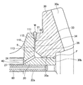
図2は、図1に示した差動装置10における、デフケース20とデフリングギヤ30との接合部分の周囲を拡大して示している。かかる図2において、溶接部Wには、溶接前のデフリングギヤ30及びデフケース20(フランジ部110)の形状が点線で示されている。デフケース20の外周部20aは、デフリングギヤ30の内周部30bに嵌合され、圧入されている。デフケース20にデフリングギヤ30を組み付ける際には、図2中の右側からデフリングギヤ30がデフケース20に嵌め込まれ、デフリングギヤ30はデフケース20のフランジ部110に当接される。デフケース20とデフリングギヤ30との嵌合部Fは、全周に亘って形成される。
FIG. 2 is an enlarged view of the periphery of the joint portion between the
デフリングギヤ30は、デフケース20のフランジ部110に対向する部分に、外周側から順に、傾斜部31、当接部32、空間形成凹部33、平坦部34及び面取部35を有する。傾斜部31は、当接部32から外周側に離れるにつれてフランジ部110から離れる面として形成される。また、当接部32及び平坦部34は、例えば、同一面上に存在する面とすることができる。空間形成凹部33は、当接部32と平坦部34との間に設けられ、フランジ部110から離れる方向へと後退した溝として形成される。
The
また、デフケース20のフランジ部110は、デフリングギヤ30に対向する部分に、外周側から順に、傾斜部111、当接部112及び空間形成凹部113を有する。傾斜部111は、当接部112から外周側に離れるにつれてデフリングギヤ30から離れる面として形成される。また、空間形成凹部113は、当接部112よりも内周側に設けられ、デフリングギヤ30から離れる方向へと後退した溝として形成される。
Further, the
また、デフケース20は、デフリングギヤ30の内周部30bと嵌合する外周部20aに連なる面であって、デフリングギヤ30の面取部35に対向する面に開口する連通孔26を有する。連通孔26の他端は、ピニオンシャフト40の抜け落ちを防止する抜け止めピン80が圧入されるピン挿入孔22aの内周面に開口する。ピン挿入孔22aの内周面に開口する連通孔26の開口端は、差動装置10が組み立てられた状態において、抜け止めピン80が挿入され得る位置に配置される。すなわち、連通孔26は、抜け止めピン80の圧入前には、ピン挿入孔22aを介してデフケース20の外部に連通する一方、抜け止めピン80の圧入後には、抜け止めピン80の外周面によって閉塞されている。
Further, the
デフリングギヤ30の内周部30bにデフケース20の外周部20aが圧入されて、デフリングギヤ30の当接部32とデフケース20の当接部112とが当接した状態では、デフリングギヤ30及びフランジ部110にそれぞれ形成された傾斜部31,111によって開先部Gが形成される。また、かかる状態においては、デフリングギヤ30及びフランジ部110にそれぞれ形成された空間形成凹部33,113により貫通空間部Sが形成される。
When the outer
デフケース20とデフリングギヤ30とが溶接される際には、かかる開先部Gにフィラーワイヤが供給されつつ、外周側からレーザや電子ビーム等の高エネルギのビームが照射され、フィラーワイヤ及び当接部32,112が溶融して、デフリングギヤ30及びデフケース20が溶接される。このとき、フィラーワイヤ及び当接部32,112が溶融して成る溶融金属が貫通空間部Sに到達するようにビームが照射され、貫通溶接とされる。デフケース20とデフリングギヤ30との溶接部W、及び上記の貫通空間部Sは、全周に亘って形成される。
When the
ここで、差動装置10の製造時において、デフケース20とデフリングギヤ30との接合は、ピニオンシャフト40やピニオンベベルギヤ50,55等をデフケース20に組み付ける前に行われる。換言すれば、デフケース20とデフリングギヤ30との溶接が行われる段階では、ピニオンシャフト40の抜け落ちを防ぐための抜け止めピン80がピン挿入孔22aに圧入されていない。したがって、デフケース20とデフリングギヤ30との溶接時には、連通孔26及びピン挿入孔22aを介して、貫通空間部Sが外部に開放されている。すなわち、連通孔26及びピン挿入孔22aは、抜け止めピン80の圧入前においては、貫通空間部Sをデフケース20の外部に連通させる連通路として機能する。かかる連通路は、抜け止めピン80の圧入後においては、当該抜け止めピン80によって閉塞され、貫通空間部Sは閉塞された空間となる。
Here, at the time of manufacturing the
上記した貫通溶接を施す場合、供給される熱、あるいは、発生する熱によって、貫通空間部S内のガスが膨張する。貫通空間部Sが外部に開放されていない場合には、貫通空間部S内のガスの膨張によって、貫通空間部S内の圧力が上昇し、溶接部Wの溶融金属の一部からガスが噴き出して、溶融部Wに穴が開く欠陥が生じる。本実施形態にかかる溶接構造では、デフケース20とデフリングギヤ30との溶接時には、連通孔26及びピン挿入孔22aを介して貫通空間部Sが外部に開放されている。したがって、図3に示すように、貫通空間部S内で膨張するガスは、連通孔26及びピン挿入孔22aを介して、デフケース20の外部に逃がされる。これにより、貫通空間部S内の圧力の上昇が抑制されて、溶融部Wに穴が開くような欠陥を防ぐことができる。
When performing the above-mentioned penetration welding, the gas in penetration space part S expands with the supplied heat or generated heat. When the through space portion S is not open to the outside, the pressure in the through space portion S increases due to the expansion of the gas in the through space portion S, and the gas is ejected from a part of the molten metal in the welded portion W As a result, a defect occurs in which a hole is formed in the melted portion W. In the welding structure according to the present embodiment, when the
連通孔26の断面形状や断面積、数は、デフケース20とデフリングギヤ30との溶接時に貫通空間部Sからガスを排出できる限り、特に限定されない。ただし、穴開け加工を容易にするために、断面形状は円形としてもよい。また、連通孔26の数が多すぎたり、断面積が大きすぎたりすると、溶接時に溶融部Wの溶け落ちを防ぐために貫通空間部S側から溶融部Wに作用させる反力が低下し、溶接性が低下するおそれがある。したがって、例えば、直径が1〜5mm程度の連通孔26が1つ設けられていればよい。
The cross-sectional shape, cross-sectional area, and number of the communication holes 26 are not particularly limited as long as the gas can be discharged from the through space portion S when the
また、本実施形態にかかる溶接構造では、差動装置10が組み立てられて、トランスミッション装置に組み付けられる状態においては、抜け止めピン80によって貫通空間部Sが閉塞された空間となっている(図2を参照)。したがって、デフケース20とデフリングギヤ30との圧入時やビーム溶接時に発生し、貫通空間部S内に存在する圧入粉やスパッタ等の異物が、差動装置10の外部に排出されることを防ぐことができる。これにより、これらの圧入粉やスパッタ等の異物が、トランスミッション装置の内部にコンタミとして混入することを防ぐことができる。
In the welded structure according to the present embodiment, when the
また、本実施形態にかかる溶接構造は、ピニオンシャフト40の抜け落ちを防ぐための抜け止めピン80により、連通孔26及びピン挿入孔22aにより形成される連通路が閉塞されるものであり、連通路を閉塞するための追加のプラグ等を要しない。したがって、追加工程を設ける必要がなく、また、生産コストが上昇することもない。
Further, in the welding structure according to the present embodiment, the communication path formed by the
(1−3.変形例)
以上、本実施形態にかかる溶接構造の一例について説明したが、かかる溶接構造は種々の変形が可能である。以下、溶接構造の一変形例について説明する。
(1-3. Modifications)
As described above, an example of the welded structure according to the present embodiment has been described. However, the welded structure can be variously modified. Hereinafter, a modification of the welded structure will be described.
図4は、変形例にかかる溶接構造を示す断面図であって、デフケース20とデフリングギヤ30との接合部分の周囲を拡大して示している。上記実施形態にかかる溶接構造では、貫通空間部Sと、抜け止めピン80が圧入されるピン挿入孔22aとを連通する連通孔26が設けられていたが、変形例にかかる溶接構造では、貫通空間部Sと、ピニオンシャフト40が挿入されるシャフト支持孔24とを連通する連通孔27が設けられている。
FIG. 4 is a cross-sectional view showing a welding structure according to a modified example, and shows an enlarged periphery of a joint portion between the
差動装置10の製造時において、ピニオンシャフト40がシャフト支持孔24に挿入される前に、デフケース20とデフリングギヤ30との溶接が行われる。したがって、デフケース20とデフリングギヤ30との溶接時には、連通孔27及びシャフト支持孔24を介して、貫通空間部Sが外部に開放されている。すなわち、連通孔27及びシャフト支持孔24は、ピニオンシャフト40の挿入前においては、貫通空間部Sをデフケース20の外部に連通させる連通路として機能する。また、かかる連通路は、ピニオンシャフト40の挿入後においては、当該ピニオンシャフト40によって閉塞され、貫通空間部Sは閉塞された空間となる。
When the
したがって、デフケース20とデフリングギヤ30との溶接時においては、貫通空間部S内で膨張するガスが、連通孔27及びシャフト支持孔24を介して、デフケース20の外部に逃がされる。これにより、貫通空間部S内の圧力の上昇が抑制されて、溶融部Wに穴が開くような欠陥を防ぐことができる。一方、差動装置10が組み立てられて、トランスミッション装置に組み付けられる状態においては、貫通空間部Sは閉塞されており、貫通空間部S内に存在する圧入粉やスパッタ等の異物が、差動装置10の外部に排出されることを防ぐことができる。これにより、圧入粉やスパッタ等の異物が、トランスミッション装置の内部にコンタミとして混入することを防ぐことができる。
Therefore, during welding of the
また、変形例にかかる溶接構造は、ピニオンシャフト40により、連通孔27及びシャフト支持孔24により形成される連通路が閉塞されるものであり、連通路を閉塞するための追加のプラグ等を要しない。したがって、追加工程を設ける必要がなく、また、生産コストが上昇することもない。
In the welding structure according to the modification, the communication path formed by the
<2.第2の実施の形態>
次に、本発明の第2の実施の形態にかかる溶接構造について説明する。本実施形態にかかる溶接構造も車両に搭載される差動装置にかかるものであり、本実施形態にかかる差動装置の基本構成は、第1の実施の形態で説明した差動装置10と同様とすることができる。以下、本実施形態にかかる溶接構造について、主として第1の実施の形態にかかる溶接構造と異なる点を説明する。
<2. Second Embodiment>
Next, the welding structure concerning the 2nd Embodiment of this invention is demonstrated. The welding structure according to this embodiment is also related to a differential device mounted on a vehicle, and the basic configuration of the differential device according to this embodiment is the same as that of the
図5は、本実施形態にかかる溶接構造を示す断面図であって、デフケース20とデフリングギヤ30との接合部分を含む、差動装置10Aの一部を示している。本実施形態にかかる差動装置10Aでは、ピニオンシャフト40の抜け落ちを防ぐ抜け止めピン84が、デフケース20に設けられたピン挿入孔23a,23b、及び、ピニオンシャフト40に設けられたピン挿入孔40aを貫通するように圧入されている。ここで用いられる抜け止めピン80は、断面がC字状の適合ピンではなく、内部孔を有しない圧入ピンである。デフケース20に設けられたピン挿入孔23aは、その一端が、直接、貫通空間部Sに開口し、他端がシャフト支持孔24の内周面に開口する。
FIG. 5 is a cross-sectional view showing the welded structure according to the present embodiment, and shows a part of the
差動装置10Aの製造時において、ピニオンシャフト40がデフケース20に組み付けられる前に、デフケース20とデフリングギヤ30との溶接が行われる。すなわち、デフケース20とデフリングギヤ30との溶接時には、ピン挿入孔23aに抜け止めピン84が圧入されておらず、また、シャフト支持孔24にピニオンシャフト40が挿入されていない。したがって、デフケース20とデフリングギヤ30との溶接時には、ピン挿入孔23a及びシャフト支持孔24を介して、貫通空間部Sが外部に開放されている。かかるピン挿入孔23a及びシャフト支持孔24は、貫通空間部Sをデフケース20の外部に連通させる連通路として機能する。また、かかる連通路は、ピン挿入孔23aに抜け止めピン84が挿入された後においては、当該抜け止めピン84によって閉塞され、貫通空間部Sは閉塞された空間となる。
At the time of manufacturing the
したがって、デフケース20とデフリングギヤ30との溶接時においては、貫通空間部S内で膨張するガスが、ピン挿入孔23a及びシャフト支持孔24を介して、デフケース20の外部に逃がされる。これにより、貫通空間部S内の圧力の上昇が抑制されて、溶融部Wに穴が開くような欠陥を防ぐことができる。一方、差動装置10Aが組み立てられて、トランスミッション装置に組み付けられる状態においては、貫通空間部Sは閉塞されており、貫通空間部S内に存在する圧入粉やスパッタ等の異物が、差動装置10Aの外部に排出されることを防ぐことができる。これにより、圧入粉やスパッタ等の異物が、トランスミッション装置の内部にコンタミとして混入することを防ぐことができる。
Therefore, during welding of the
また、本実施形態にかかる溶接構造は、抜け止めピン84により、ピン挿入孔23a及びシャフト支持孔24により形成される連通路が閉塞されるものであり、連通路を閉塞するための追加のプラグ等を要しない。したがって、追加工程を設ける必要がなく、また、生産コストが上昇することもない。
Further, the welding structure according to the present embodiment is such that the communication path formed by the
<3.まとめ>
以上説明したように上記各実施形態にかかる溶接構造は、デフケース20とデフリングギヤ30との溶接時において、嵌合部Fと溶接部Wとの間に形成される貫通空間部Sを外部に連通させる連通路を有する。したがって、デフケース20とデフリングギヤ30との溶接時に、供給される熱、あるいは、発生する熱によって膨張する貫通空間部S内のガスが、連通路を介して外部に逃がされる。これにより、貫通空間部Sの内部圧力の上昇が抑制され、溶融部Wに穴が開くような欠陥が防止される。
<3. Summary>
As described above, the welding structure according to each of the above embodiments communicates the through space portion S formed between the fitting portion F and the welded portion W to the outside when the
また、上記の連通路は、差動装置10,10Aの組み付け後においては、連通路に圧入又は挿入される抜け止めピン80,84又はピニオンシャフト40によって閉塞され、貫通空間部Sが閉塞された空間となる。これにより、差動装置10,10Aがトランスミッション装置に組み付けられた後に、圧入粉やスパッタ等の異物が、貫通空間部Sから差動装置10,10A外に排出され、トランスミッション装置内にコンタミとして混入されることがない。
Further, after the assembly of the
そして、上記の連通路を閉塞する抜け止めピン80,84又はピニオンシャフト40は、それぞれピニオンシャフト40の抜け落ちを防ぐ機能、又は、ピニオンベベルギヤ50,55を支持する機能を有するものであり、連通路を閉塞するために追加的に設けられるものではない。したがって、差動装置10の製造工程において、追加の組立工程及び生産コストの増加を伴うことなく、貫通空間部Sからのガス抜き用の連通路を閉塞することができる。
The retaining pins 80 and 84 or the
以上、添付図面を参照しながら本発明の好適な実施形態について詳細に説明したが、本発明はかかる例に限定されない。本発明の属する技術の分野における通常の知識を有する者であれば、特許請求の範囲に記載された技術的思想の範疇内において、各種の変更例または修正例に想到し得ることは明らかであり、これらについても、当然に本発明の技術的範囲に属するものと了解される。 The preferred embodiments of the present invention have been described in detail above with reference to the accompanying drawings, but the present invention is not limited to such examples. It is obvious that a person having ordinary knowledge in the technical field to which the present invention pertains can come up with various changes or modifications within the scope of the technical idea described in the claims. Of course, it is understood that these also belong to the technical scope of the present invention.
例えば、上記実施形態では、デフケース20側にガス抜き用の連通路を設ける例を説明したが、本発明はかかる例に限定されない。例えば、デフリングギヤ30側に、他の機能を有する挿入部材が挿入される挿入孔が設けられる場合には、当該挿入孔と貫通空間部Sとを連通する連通孔を形成し、デフリングギヤ30側にガス抜き用の連通路を設けてもよい。
For example, in the above-described embodiment, the example in which the communication path for degassing is provided on the
また、上記実施形態では、本発明の溶接構造を差動装置に適用した例を説明したが、本発明はかかる例に限定されない。本発明にかかる溶接構造は、ビーム溶接等の溶接時に、内部のガスが熱によって膨張し得る空間部が存在する溶接構造であれば他の構造物に対しても適用可能である。この場合、第1の部材又は第2の部材における空間部から連通孔を介して連通可能な位置に、他の機能を有する挿入部材が挿入される挿入孔が存在し、かつ、第1の部材と第2の部材との溶接工程の後に挿入孔に挿入部材が挿入されるように構成されていればよい。例えば、本発明にかかる溶接構造は、差動制限機構付きの差動装置に適用されてもよい。 Moreover, although the said embodiment demonstrated the example which applied the welding structure of this invention to the differential gear, this invention is not limited to this example. The welded structure according to the present invention can be applied to other structures as long as the welded structure has a space in which internal gas can be expanded by heat during welding such as beam welding. In this case, the first member or the second member has an insertion hole into which an insertion member having another function is inserted at a position where the first member or the second member can communicate via the communication hole, and the first member. What is necessary is just to be comprised so that an insertion member may be inserted in an insertion hole after the welding process with a 2nd member. For example, the welding structure according to the present invention may be applied to a differential device with a differential limiting mechanism.
10・10A 差動装置
20 デフケース
22a・22b ピン挿入孔
24 シャフト支持孔
26・27 連通孔
30 デフリングギヤ
40 ピニオンシャフト
80・84 抜け止めピン
F 嵌合部
S 貫通空間部
W 溶接部
10.10A
Claims (8)
前記第1の部材及び前記第2の部材のいずれか一方は、一端が前記空間部に開口し、他端が前記空間部以外の位置で外部に開口した連通路を有し、
当該連通路を閉塞すること以外の所定の機能を有する挿入部材によって前記連通路が閉塞される、溶接構造。 A fitting portion where the first member and the second member are fitted, a welded portion where the first member and the second member are welded, and between the fitting portion and the welded portion A welded structure comprising a formed space portion,
One of the first member and the second member has a communication path having one end opened to the space and the other end opened to the outside at a position other than the space.
A welding structure in which the communication path is closed by an insertion member having a predetermined function other than closing the communication path.
前記挿入孔の内周面に開口する前記連通孔の開口端が、前記挿入部材によって閉鎖される、請求項1に記載の溶接構造。 The communication path includes an insertion hole into which the insertion member is inserted, and a communication hole that communicates the space portion and the insertion hole.
The welding structure according to claim 1, wherein an opening end of the communication hole that opens to an inner peripheral surface of the insertion hole is closed by the insertion member.
前記挿入部材は、ピニオンギヤを支持するピニオンシャフトの抜け落ちを防ぐための抜け止めピンであり、
前記連通路は、前記抜け止めピンが挿入される挿入孔と、前記空間部及び前記挿入孔を連通する連通孔と、を含んで形成され、
前記挿入孔の内周面に開口する前記連通孔の開口端が、前記抜け止めピンによって閉鎖される、請求項2に記載の溶接構造。 The first member and the second member are a differential case and a ring gear,
The insertion member is a retaining pin for preventing the pinion shaft supporting the pinion gear from falling off,
The communication path includes an insertion hole into which the retaining pin is inserted, and a communication hole that communicates the space portion and the insertion hole.
The welding structure according to claim 2, wherein an opening end of the communication hole that opens to an inner peripheral surface of the insertion hole is closed by the retaining pin.
前記挿入部材は、ピニオンギヤを支持するピニオンシャフトであり、
前記連通路は、前記ピニオンシャフトが挿入されるシャフト挿入孔と、前記空間部及び前記シャフト挿入孔を連通する連通孔と、を含んで形成され、
前記シャフト挿入孔の内周面に開口する前記連通孔の開口端が、前記ピニオンシャフトによって閉鎖される、請求項2に記載の溶接構造。 The first member and the second member are a differential case and a ring gear,
The insertion member is a pinion shaft that supports a pinion gear;
The communication path includes a shaft insertion hole into which the pinion shaft is inserted, and a communication hole that communicates the space portion and the shaft insertion hole.
The welding structure according to claim 2, wherein an open end of the communication hole that opens to an inner peripheral surface of the shaft insertion hole is closed by the pinion shaft.
前記挿入部材は、ピニオンギヤを支持するピニオンシャフトの抜け落ちを防ぐための抜け止めピンであり、
前記連通路は、一端が前記空間部に開口し、他端から前記抜け止めピンが挿入される挿入孔である、請求項5に記載の溶接構造。 The first member and the second member are a differential case and a ring gear,
The insertion member is a retaining pin for preventing the pinion shaft supporting the pinion gear from falling off,
The welding structure according to claim 5, wherein one end of the communication path is an insertion hole that opens into the space and into which the retaining pin is inserted from the other end.
The welding structure according to any one of claims 1 to 7, wherein the welded portion is beam welding performed by supplying a filler wire, and is formed by penetration welding reaching the space portion.
Priority Applications (4)
| Application Number | Priority Date | Filing Date | Title |
|---|---|---|---|
| JP2015187949A JP6196271B2 (en) | 2015-09-25 | 2015-09-25 | Welded structure and manufacturing method of welded structure |
| US15/249,012 US9933061B2 (en) | 2015-09-25 | 2016-08-26 | Weld structure |
| CN201610832320.2A CN106555862B (en) | 2015-09-25 | 2016-09-19 | Welding structure |
| DE102016218087.8A DE102016218087A1 (en) | 2015-09-25 | 2016-09-21 | welded structure |
Applications Claiming Priority (1)
| Application Number | Priority Date | Filing Date | Title |
|---|---|---|---|
| JP2015187949A JP6196271B2 (en) | 2015-09-25 | 2015-09-25 | Welded structure and manufacturing method of welded structure |
Publications (2)
| Publication Number | Publication Date |
|---|---|
| JP2017062003A true JP2017062003A (en) | 2017-03-30 |
| JP6196271B2 JP6196271B2 (en) | 2017-09-13 |
Family
ID=58282180
Family Applications (1)
| Application Number | Title | Priority Date | Filing Date |
|---|---|---|---|
| JP2015187949A Active JP6196271B2 (en) | 2015-09-25 | 2015-09-25 | Welded structure and manufacturing method of welded structure |
Country Status (4)
| Country | Link |
|---|---|
| US (1) | US9933061B2 (en) |
| JP (1) | JP6196271B2 (en) |
| CN (1) | CN106555862B (en) |
| DE (1) | DE102016218087A1 (en) |
Cited By (3)
| Publication number | Priority date | Publication date | Assignee | Title |
|---|---|---|---|---|
| WO2019044502A1 (en) * | 2017-08-31 | 2019-03-07 | アイシン・エィ・ダブリュ株式会社 | Method for manufacturing differential device |
| JP2020175418A (en) * | 2019-04-18 | 2020-10-29 | マツダ株式会社 | Laser welding method and laser welding equipment |
| WO2020255524A1 (en) * | 2019-06-21 | 2020-12-24 | 日立オートモティブシステムズ株式会社 | Joint structure and high-pressure fuel supply pump using same |
Families Citing this family (8)
| Publication number | Priority date | Publication date | Assignee | Title |
|---|---|---|---|---|
| WO2016148292A1 (en) * | 2015-03-19 | 2016-09-22 | アイシン・エィ・ダブリュ株式会社 | Joint component and method of manufacturing same |
| US11231099B2 (en) * | 2016-11-09 | 2022-01-25 | Arvinmeritor Technology, Llc | Axle assembly and differential assembly with spider shaft retention |
| JP2019070420A (en) * | 2017-10-10 | 2019-05-09 | トヨタ自動車株式会社 | Vehicular differential device |
| US10781908B2 (en) * | 2017-12-11 | 2020-09-22 | Gkn Automotive Limited | Driveline components with weld vent |
| US11213917B2 (en) * | 2018-11-13 | 2022-01-04 | GM Global Technology Operations LLC | Fusion welding of ferrous alloy component parts using low carbon steel band |
| DE102018220105B4 (en) * | 2018-11-22 | 2021-01-21 | Audi Ag | Differential gear for a motor vehicle with an output gear pressed onto the housing through two press fits |
| DE102022201298A1 (en) | 2022-02-08 | 2023-08-10 | Mahle International Gmbh | Process for manufacturing a component |
| US11873888B1 (en) * | 2022-11-18 | 2024-01-16 | GM Global Technology Operations LLC | Differential carrier and ring gear assembly |
Citations (4)
| Publication number | Priority date | Publication date | Assignee | Title |
|---|---|---|---|---|
| JP2010174924A (en) * | 2009-01-27 | 2010-08-12 | Toyota Motor Corp | Differential device |
| WO2011089706A1 (en) * | 2010-01-22 | 2011-07-28 | トヨタ自動車株式会社 | Welded structure and welding method |
| JP2011169444A (en) * | 2010-02-22 | 2011-09-01 | Nissan Motor Co Ltd | Beam welding member and differential gear equipped with the same |
| WO2013018223A1 (en) * | 2011-08-04 | 2013-02-07 | トヨタ自動車株式会社 | Welding structure and method for manufacturing welding structure |
Family Cites Families (10)
| Publication number | Priority date | Publication date | Assignee | Title |
|---|---|---|---|---|
| US2651216A (en) * | 1949-02-28 | 1953-09-08 | Timken Axle Co Detroit | Differential mounting and carrier |
| JPS5166629A (en) * | 1974-12-02 | 1976-06-09 | Toyota Motor Co Ltd | |
| DE3437823A1 (en) | 1984-10-16 | 1986-04-17 | Borsig Gmbh, 1000 Berlin | WELDED JOINT |
| DE3642875A1 (en) * | 1986-12-16 | 1988-07-07 | Daimler Benz Ag | STORAGE OF A DIFFERENTIAL HOUSING OF A DIFFERENTIAL GEARBOX IN AN AXLE GEARBOX HOUSING OF A MOTOR VEHICLE |
| JPH0314066A (en) | 1989-06-13 | 1991-01-22 | Fujitsu Ltd | Japanese rendering character display and editing system |
| DE4313322C2 (en) * | 1993-04-23 | 2001-08-02 | Porsche Ag | Differential for the final drive of a motor vehicle |
| DE102005023230B4 (en) * | 2005-05-04 | 2010-10-07 | Bayerische Motoren Werke Aktiengesellschaft | Method for welding a ring gear with a differential housing of a transmission |
| US7572202B2 (en) * | 2007-01-31 | 2009-08-11 | American Axle & Manufacturing, Inc. | Electronic locking differential with direct locking state detection system |
| JP4826651B2 (en) * | 2009-04-09 | 2011-11-30 | トヨタ自動車株式会社 | Differential gear |
| JP2015187949A (en) | 2014-03-27 | 2015-10-29 | 株式会社日立製作所 | lithium ion secondary battery |
-
2015
- 2015-09-25 JP JP2015187949A patent/JP6196271B2/en active Active
-
2016
- 2016-08-26 US US15/249,012 patent/US9933061B2/en active Active
- 2016-09-19 CN CN201610832320.2A patent/CN106555862B/en active Active
- 2016-09-21 DE DE102016218087.8A patent/DE102016218087A1/en active Pending
Patent Citations (4)
| Publication number | Priority date | Publication date | Assignee | Title |
|---|---|---|---|---|
| JP2010174924A (en) * | 2009-01-27 | 2010-08-12 | Toyota Motor Corp | Differential device |
| WO2011089706A1 (en) * | 2010-01-22 | 2011-07-28 | トヨタ自動車株式会社 | Welded structure and welding method |
| JP2011169444A (en) * | 2010-02-22 | 2011-09-01 | Nissan Motor Co Ltd | Beam welding member and differential gear equipped with the same |
| WO2013018223A1 (en) * | 2011-08-04 | 2013-02-07 | トヨタ自動車株式会社 | Welding structure and method for manufacturing welding structure |
Cited By (6)
| Publication number | Priority date | Publication date | Assignee | Title |
|---|---|---|---|---|
| WO2019044502A1 (en) * | 2017-08-31 | 2019-03-07 | アイシン・エィ・ダブリュ株式会社 | Method for manufacturing differential device |
| JPWO2019044502A1 (en) * | 2017-08-31 | 2020-02-27 | アイシン・エィ・ダブリュ株式会社 | Manufacturing method of differential device |
| JP2020175418A (en) * | 2019-04-18 | 2020-10-29 | マツダ株式会社 | Laser welding method and laser welding equipment |
| WO2020255524A1 (en) * | 2019-06-21 | 2020-12-24 | 日立オートモティブシステムズ株式会社 | Joint structure and high-pressure fuel supply pump using same |
| JPWO2020255524A1 (en) * | 2019-06-21 | 2020-12-24 | ||
| JP7249411B2 (en) | 2019-06-21 | 2023-03-30 | 日立Astemo株式会社 | JOINT STRUCTURE AND HIGH PRESSURE FUEL SUPPLY PUMP USING THE SAME |
Also Published As
| Publication number | Publication date |
|---|---|
| CN106555862B (en) | 2018-09-14 |
| US9933061B2 (en) | 2018-04-03 |
| CN106555862A (en) | 2017-04-05 |
| DE102016218087A1 (en) | 2017-03-30 |
| JP6196271B2 (en) | 2017-09-13 |
| US20170089440A1 (en) | 2017-03-30 |
Similar Documents
| Publication | Publication Date | Title |
|---|---|---|
| JP6196271B2 (en) | Welded structure and manufacturing method of welded structure | |
| JP6501584B2 (en) | Transmission | |
| JP5509910B2 (en) | Beam welding member and differential device provided with the same | |
| JP5614054B2 (en) | Beam welding member and differential device provided with the same | |
| JP6217023B2 (en) | Differential device and manufacturing method thereof | |
| KR20110122738A (en) | Differential gear and vehicle provided with differential gear | |
| JP6335983B2 (en) | Method for manufacturing differential device and differential device | |
| CN107676455B (en) | Differential gear | |
| JP2015124874A5 (en) | ||
| JP2019082204A (en) | Differential device | |
| US10781908B2 (en) | Driveline components with weld vent | |
| US11841069B2 (en) | Power transmission device | |
| JP5359813B2 (en) | Vehicle differential switching device | |
| US20220196131A1 (en) | Differential device | |
| WO2020262627A1 (en) | Power transmission device | |
| JP2021008899A (en) | Transmission device | |
| CN109654193B (en) | Vehicle differential device and welding method thereof | |
| JP2017198238A (en) | Differential gear case | |
| JP7064369B2 (en) | Welding method and welding structure | |
| JP6710796B2 (en) | Transmission | |
| JP2022165158A (en) | Vehicle differential device | |
| WO2019044502A1 (en) | Method for manufacturing differential device | |
| WO2019187212A1 (en) | Differential gear device | |
| JP2019086156A5 (en) | ||
| JP2012189116A (en) | Member fixing structure |
Legal Events
| Date | Code | Title | Description |
|---|---|---|---|
| A131 | Notification of reasons for refusal |
Free format text: JAPANESE INTERMEDIATE CODE: A131 Effective date: 20170110 |
|
| A521 | Request for written amendment filed |
Free format text: JAPANESE INTERMEDIATE CODE: A523 Effective date: 20170310 |
|
| TRDD | Decision of grant or rejection written | ||
| A01 | Written decision to grant a patent or to grant a registration (utility model) |
Free format text: JAPANESE INTERMEDIATE CODE: A01 Effective date: 20170725 |
|
| A61 | First payment of annual fees (during grant procedure) |
Free format text: JAPANESE INTERMEDIATE CODE: A61 Effective date: 20170817 |
|
| R150 | Certificate of patent or registration of utility model |
Ref document number: 6196271 Country of ref document: JP Free format text: JAPANESE INTERMEDIATE CODE: R150 |
|
| R250 | Receipt of annual fees |
Free format text: JAPANESE INTERMEDIATE CODE: R250 |
|
| R250 | Receipt of annual fees |
Free format text: JAPANESE INTERMEDIATE CODE: R250 |
|
| R250 | Receipt of annual fees |
Free format text: JAPANESE INTERMEDIATE CODE: R250 |
|
| R250 | Receipt of annual fees |
Free format text: JAPANESE INTERMEDIATE CODE: R250 |