JP2017052419A - Holding structure of vehicular battery - Google Patents
Holding structure of vehicular battery Download PDFInfo
- Publication number
- JP2017052419A JP2017052419A JP2015178136A JP2015178136A JP2017052419A JP 2017052419 A JP2017052419 A JP 2017052419A JP 2015178136 A JP2015178136 A JP 2015178136A JP 2015178136 A JP2015178136 A JP 2015178136A JP 2017052419 A JP2017052419 A JP 2017052419A
- Authority
- JP
- Japan
- Prior art keywords
- battery
- tray
- lock arm
- holding structure
- fixed beam
- Prior art date
- Legal status (The legal status is an assumption and is not a legal conclusion. Google has not performed a legal analysis and makes no representation as to the accuracy of the status listed.)
- Granted
Links
- 238000007689 inspection Methods 0.000 abstract description 12
- 238000012423 maintenance Methods 0.000 abstract description 12
- 230000000452 restraining effect Effects 0.000 abstract description 2
- 238000012986 modification Methods 0.000 description 5
- 230000004048 modification Effects 0.000 description 5
- 230000000694 effects Effects 0.000 description 1
- 239000000446 fuel Substances 0.000 description 1
- 238000009434 installation Methods 0.000 description 1
- 230000036544 posture Effects 0.000 description 1
- 238000005096 rolling process Methods 0.000 description 1
Images

Classifications
-
- Y—GENERAL TAGGING OF NEW TECHNOLOGICAL DEVELOPMENTS; GENERAL TAGGING OF CROSS-SECTIONAL TECHNOLOGIES SPANNING OVER SEVERAL SECTIONS OF THE IPC; TECHNICAL SUBJECTS COVERED BY FORMER USPC CROSS-REFERENCE ART COLLECTIONS [XRACs] AND DIGESTS
- Y02—TECHNOLOGIES OR APPLICATIONS FOR MITIGATION OR ADAPTATION AGAINST CLIMATE CHANGE
- Y02T—CLIMATE CHANGE MITIGATION TECHNOLOGIES RELATED TO TRANSPORTATION
- Y02T10/00—Road transport of goods or passengers
- Y02T10/60—Other road transportation technologies with climate change mitigation effect
- Y02T10/70—Energy storage systems for electromobility, e.g. batteries
Abstract
Description
本発明は、車両用バッテリの保持構造に関するものである。 The present invention relates to a vehicle battery holding structure.
近年においては、エンジンとモータジェネレータとを併用した燃費性能の高いハイブリッド自動車の開発が進められているが、この種のハイブリッド自動車では、電力走行用電源を成すバッテリを搭載する必要があり、特にハイブリッドバス等においては、ボデーの側面に設けた格納庫に対し引き出し式に出し入れし得るようにトレイを設置し、このトレイにバッテリを上載して保持させるようにしている。 In recent years, the development of hybrid vehicles with high fuel efficiency performance using a combination of an engine and a motor generator has been promoted. However, in this type of hybrid vehicle, it is necessary to install a battery that serves as a power source for electric power traveling. In a bus or the like, a tray is installed so that it can be pulled out and put in and out of a storage provided on the side of the body, and a battery is placed on the tray and held.
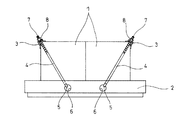
図4は従来の車両用バッテリの保持構造を示すもので、ここに図示している例では、二つの角形のバッテリ1が並べてトレイ2に上載されており、このバッテリ1が並べられている方向を幅方向として規定すると共に、該幅方向に対し直角な水平方向を前後方向として規定している。
FIG. 4 shows a conventional vehicle battery holding structure. In the example shown here, two
そして、これらのバッテリ1の上部における幅方向両側の角部が一対の固定ビーム3により押さえ込まれるようになっていて、該各固定ビーム3が前記トレイ2側から延びるロックアーム4により拘束されるようになっており、走行振動等に対しバッテリ1が安定して保持されるようにしてある。
And the corner | angular part of the width direction both sides in the upper part of these
ここで、前記ロックアーム4の基端部は、釣り針状に巻き返されてフック部5を成すようにしてあり、前記トレイ2の前後端面の夫々に二つずつ開けられた係止孔6に対し前記フック部5が引っ掛けられて係止されるようになっている一方、前記ロックアーム4の先端部は、ボルトの如き雄ネジ部7として形成されていて、前記固定ビーム3の前後端部に対し貫通してナット8により締結されるようになっている。
Here, the base end portion of the
尚、この種の車両用バッテリの保持構造に関連する先行技術文献情報としては下記の特許文献1等がある。
The prior art document information related to this type of vehicle battery holding structure includes the following
しかしながら、斯かる従来構造においては、バッテリ1の点検整備時にナット8を取り外してから固定ビーム3やロックアーム4を全て撤去してバッテリ1を取り外すようにしているため、該バッテリ1の取り外しやその後の取り付け直しの作業に手間がかかるという問題があり、特にハイブリッドバス等に採用されている引き出し式のトレイ2の場合に格納庫の奥側での作業が非常に煩わしいものとなることから、バッテリ1の点検整備時における作業性の改善が望まれている。
However, in such a conventional structure, when the
ここで、トレイ2側の係止孔6は、ロックアーム4のフック部5を引っ掛け易くするために相対的に大きく開口されているが、ナット8の緩みによりロックアーム4に引っ張り荷重が作用しなくなれば、各固定ビーム3をバッテリ1の角部から外した際にロックアーム4や固定ビーム3が姿勢保持できなくなって全体形状が崩れ、これらのトレイ2下への脱落を招きかねないことから、固定ビーム3やロックアーム4を全て撤去した上でバッテリ1を取り外す措置が取られている。
Here, the
一方、フック部5が外れ難くなるように係止孔6を小径化してしまうと、大きく曲げたフック部5を前記係止孔6に通すのが困難となり、ロックアーム4をトレイ2側に簡便に取り付けることができなくなってしまうため、これまでのところはバッテリ1の点検整備時における作業性に目をつぶって既存構造を踏襲し続けているのが実情である。
On the other hand, if the diameter of the
本発明は上述の実情に鑑みてなしたもので、バッテリの点検整備時における作業性を従来よりも大幅に改善し得るようにした車両用バッテリの保持構造を提供することを目的とする。 The present invention has been made in view of the above-described circumstances, and an object of the present invention is to provide a vehicle battery holding structure capable of significantly improving the workability at the time of battery inspection and maintenance.
本発明は、バッテリを上載するトレイと、前記バッテリ上部両側の角部を押さえ込む一対の固定ビームと、該各固定ビームを前記バッテリ上部両側の角部を押さえ込ませた状態でトレイ側から拘束するロックアームとを備えた車両用バッテリの保持構造であって、前記ロックアームの基端部を前記各固定ビームの対峙方向に傾動し得るよう前記トレイ側に枢支し且つ先端部を前記各固定ビームに対し締結したことを特徴とするものである。 The present invention relates to a tray on which a battery is mounted, a pair of fixed beams for pressing corners on both sides of the upper part of the battery, and a lock for restraining the fixed beams from the tray side in a state where the corners on both sides of the upper part of the battery are pressed. A vehicle battery holding structure including an arm, wherein a base end portion of the lock arm is pivotally supported on the tray side so as to be able to tilt in a direction opposite to the fixed beam, and a distal end portion is fixed to the fixed beam. It is characterized by having concluded with respect to.
而して、このようにした場合に、ロックアームの先端部と固定ビームとの締結を緩めて前記ロックアームに引っ張り荷重が作用しない状態とし、バッテリ上部両側の角部から固定ビームを外してロックアームをバッテリの外側へ倒すように傾動させると、該バッテリの外側に各固定ビームが退避した状態となり、しかも、各ロックアームがトレイ側に連結された状態のまま保持されるので、これら固定ビームやロックアームを全て撤去しないままバッテリを取り外すことが可能となる。 Thus, in this case, the lock arm is loosened by tightening the tip of the lock arm so that no tensile load acts on the lock arm, and the lock beam is removed from the corners on both sides of the upper part of the battery. When the arm is tilted to the outside of the battery, each fixed beam is retracted to the outside of the battery, and each lock arm is held in a state of being connected to the tray side. It is possible to remove the battery without removing all the lock arms.
また、バッテリの整備点検後の取り付け直しの作業では、トレイ上にバッテリを上載し直してからロックアームをバッテリの内側へ起こすように傾動させ、固定ビームを前記バッテリ上部両側の角部を押さえ込ませた状態とした上でロックアームの先端部と固定ビームとの締結を締め直すと、前記ロックアームに引っ張り荷重が作用してトレイ側から固定ビームが拘束された状態となり、点検整備後のバッテリを簡便に取り付け直すことが可能となる。 Also, in the re-installation work after the battery maintenance and inspection, the battery is remounted on the tray and then tilted to raise the lock arm to the inside of the battery, and the fixed beam is pressed down on the corners on both sides of the battery. If the fastening between the tip of the lock arm and the fixed beam is retightened, a tensile load is applied to the lock arm and the fixed beam is restrained from the tray side. It becomes possible to attach it easily.
更に、本発明をより具体的に実施するにあたっては、ロックアームの基端部が円弧状に巻き返されて係止環を成し且つ該係止環の中心を挿通させたボルトを介してトレイ側に枢支されていることが好ましく、このようにすれば、既存の構造に簡単な改造を施すだけで実施することが可能となる。 Further, in carrying out the present invention more concretely, the base end portion of the lock arm is rewound in an arc shape to form a locking ring, and the tray is inserted through a bolt inserted through the center of the locking ring. It is preferably pivoted to the side, and in this way it can be carried out with a simple modification to the existing structure.
また、トレイが車両のボデーに設けた格納庫に対し引き出し式に出し入れし得るように構成されていても良く、このように構成されている場合には、トレイを格納庫から引き出した状態でロックアームを傾動させることが可能となり、該ロックアームの傾動範囲を確保し易くなる。 In addition, the tray may be configured to be able to be withdrawn / retracted from / to the hangar provided on the body of the vehicle, and in this case, the lock arm is pulled out from the hangar. It becomes possible to tilt, and it becomes easy to ensure the tilting range of the lock arm.
上記した本発明の車両用バッテリの保持構造によれば、下記の如き種々の優れた効果を奏し得る。 According to the vehicle battery holding structure of the present invention described above, various excellent effects as described below can be obtained.
(I)本発明の請求項1に記載の発明によれば、固定ビームやロックアームを全て撤去しないままバッテリを取り外したり、点検整備後のバッテリを簡便に取り付け直したりすることができるので、バッテリの点検整備時における作業性を従来よりも大幅に改善することができる。
(I) According to the invention described in
(II)本発明の請求項2に記載の発明によれば、既存の構造に対し大掛かりな改造を施す必要がなく、既存の構造に対し簡単な改造を施すだけで実施することができるので、その実施にあたってのコストを大幅に抑制することができる。
(II) According to the invention described in
(III)本発明の請求項3に記載の発明によれば、トレイを格納庫から引き出した状態でロックアームを傾動させることができるので、該ロックアームの傾動範囲を確保し易くすることができ、バッテリの点検整備時における作業性の更なる向上を図ることができる。
(III) According to the invention described in
以下本発明の実施の形態を図面を参照しつつ説明する。 Embodiments of the present invention will be described below with reference to the drawings.
図1〜図3は本発明を実施する形態の一例を示すもので、図4と同一の符号を付した部分は同一物を表わしている。 1 to 3 show an example of an embodiment for carrying out the present invention, and the portions denoted by the same reference numerals as those in FIG. 4 represent the same items.
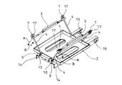
図1〜図3に示す如く、本形態例においては、先に図4で説明した既存構造の場合と同様に、二つの角形のバッテリ1が並べてトレイ2に上載されており、このバッテリ1が並べられている方向を幅方向として規定すると共に、該幅方向に対し直角な水平方向を前後方向として規定している。
As shown in FIGS. 1 to 3, in this embodiment, as in the case of the existing structure described above with reference to FIG. 4, two
そして、これらのバッテリ1の上部における幅方向両側の角部が一対の固定ビーム3により押さえ込まれるようになっていて、該各固定ビーム3が前記トレイ2側から延びるロックアーム4により拘束されるようになっているが、該ロックアーム4を前記トレイ2の前後端面に一対一組で装備して基端部を前記各固定ビーム3の対峙方向(バッテリ1の幅方向)へ傾動し得るよう枢支し且つ先端部を前記各固定ビーム3に対し締結したところを特徴としている。
And the corner | angular part of the width direction both sides in the upper part of these
ここで、ロックアーム4の基端部は、円弧状に巻き返されて係止環9を成し且つ該係止環9の中心を挿通させたボルト10を介してトレイ2側に枢支されており、該トレイ2の前後端面における前記各ボルト10の枢支位置は、二つ並べたバッテリ1の幅寸法の範囲内に設定されるようになっている。
Here, the base end portion of the
一方、ロックアーム4の先端部は、先に図4で説明した既存構造の場合と同様に、ボルトの如き雄ネジ部7として形成されていて、前記固定ビーム3の前後端部に対し貫通して蝶ナット17により締結されるようになっている。
On the other hand, the distal end portion of the
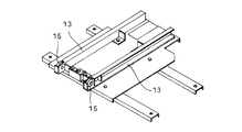
また、前記トレイ2は、ハイブリッドバス等におけるボデーの側面に設けられた格納庫11に対し引き出し式に出し入れし得るようになっており、より具体的には、シャシフレーム側から支持されているカバー12により周囲を囲まれて前記格納庫11が形成されていると共に、該格納庫11の底部に前記トレイ2を移動自在に支持するレール13が架設され且つ該レール13上に前記トレイ2下面に具備されたガイドバー14が移動自在に係合設置されている。
Further, the
ここで、前記ガイドバー14は、逆さのL字断面を成すようなアングル形状を有し且つその後端内側にガイド輪15を備えていて、前記レール13は、幅方向外側に向け溝形を成すチャンネル形状を有し且つその前端外側にガイド輪16を備えており、更には、このガイド輪16の配置されている位置における上側のフランジ面が切欠かれて前記ガイド輪16がフランジ面より高く張り出すようになっており、これら相互のガイド輪15,16の転動によりガイドバー14がレール13に沿って移動し得るようにしてある。
Here, the
而して、このようにした場合に、ロックアーム4の先端部と固定ビーム3とを締結している蝶ナット17を緩めて前記ロックアーム4に引っ張り荷重が作用しない状態とし、バッテリ1上部両側の角部から固定ビーム3を外してロックアーム4をバッテリ1の幅方向外側へ倒すように傾動させると(図2中の矢印A参照)、該バッテリ1の幅方向外側に各固定ビーム3が退避した状態となり、しかも、各ロックアーム4がトレイ2の前後端面に連結された状態のまま保持されるので、これら固定ビーム3やロックアーム4を全て撤去しないままバッテリ1を取り外すことが可能となる。
Thus, in this case, the
また、バッテリ1の整備点検後の取り付け直しの作業では、トレイ2上にバッテリ1を上載し直してからロックアーム4をバッテリ1の幅方向内側へ起こすように傾動させ(図2中の矢印B参照)、固定ビーム3を前記バッテリ1上部両側の角部を押さえ込ませた状態とした上で蝶ナット17を締め直すと、前記ロックアーム4に引っ張り荷重が作用してトレイ2側から固定ビーム3が拘束された状態となり、点検整備後のバッテリ1を簡便に取り付け直すことが可能となる。
Further, in the operation of reattaching the
従って、上記形態例によれば、固定ビーム3やロックアーム4を全て撤去しないままバッテリ1を取り外したり、点検整備後のバッテリ1を簡便に取り付け直したりすることができるので、バッテリ1の点検整備時における作業性を従来よりも大幅に改善することができる。
Therefore, according to the above embodiment, the
特に本形態例においては、ロックアーム4の基端部が円弧状に巻き返されて係止環9を成し且つ該係止環9の中心を挿通させたボルト10を介してトレイ2側に枢支させるようにしているので、既存の構造に対し大掛かりな改造を施す必要がなく、既存の構造に対し簡単な改造を施すだけで実施することができるので、その実施にあたってのコストを大幅に抑制することができる。
In particular, in the present embodiment, the base end of the
また、トレイ2が車両のボデーに設けた格納庫11に対し引き出し式に出し入れし得るように構成されているので、トレイ2を格納庫11から引き出した状態でロックアーム4を傾動させることができ、これによりロックアーム4の傾動範囲を確保し易くすることができてバッテリ1の点検整備時における作業性の更なる向上を図ることができる。
Further, since the
尚、本発明の車両用バッテリの保持構造は、上述の形態例にのみ限定されるものではなく、本発明の要旨を逸脱しない範囲内において種々変更を加え得ることは勿論である。 In addition, the vehicle battery holding structure of the present invention is not limited to the above-described embodiment, and various changes can be made without departing from the scope of the present invention.
1 バッテリ
2 トレイ
3 固定ビーム
4 ロックアーム
9 係止環
10 ボルト
11 格納庫
1
Claims (3)
Priority Applications (1)
| Application Number | Priority Date | Filing Date | Title |
|---|---|---|---|
| JP2015178136A JP6646389B2 (en) | 2015-09-10 | 2015-09-10 | Vehicle battery holding structure |
Applications Claiming Priority (1)
| Application Number | Priority Date | Filing Date | Title |
|---|---|---|---|
| JP2015178136A JP6646389B2 (en) | 2015-09-10 | 2015-09-10 | Vehicle battery holding structure |
Publications (2)
| Publication Number | Publication Date |
|---|---|
| JP2017052419A true JP2017052419A (en) | 2017-03-16 |
| JP6646389B2 JP6646389B2 (en) | 2020-02-14 |
Family
ID=58320209
Family Applications (1)
| Application Number | Title | Priority Date | Filing Date |
|---|---|---|---|
| JP2015178136A Active JP6646389B2 (en) | 2015-09-10 | 2015-09-10 | Vehicle battery holding structure |
Country Status (1)
| Country | Link |
|---|---|
| JP (1) | JP6646389B2 (en) |
Cited By (4)
| Publication number | Priority date | Publication date | Assignee | Title |
|---|---|---|---|---|
| CN107221621A (en) * | 2017-07-18 | 2017-09-29 | 徐州徐工矿山机械有限公司 | Quarry tipper storage battery installing support structure |
| JP2018160389A (en) * | 2017-03-23 | 2018-10-11 | デンヨー株式会社 | Battery assembling structure |
| CN109421503A (en) * | 2017-08-28 | 2019-03-05 | 北京华田汽车科技有限公司 | A kind of chassis crossrail runs through the battery system structure of battery pack |
| JP7359261B1 (en) | 2022-07-21 | 2023-10-11 | いすゞ自動車株式会社 | Battery fixing device and retainer used in battery fixing device |
Citations (10)
| Publication number | Priority date | Publication date | Assignee | Title |
|---|---|---|---|---|
| JPH02124661U (en) * | 1989-03-23 | 1990-10-15 | ||
| JPH0554105U (en) * | 1991-12-25 | 1993-07-20 | 日野自動車工業株式会社 | Battery fixing device for vehicle |
| JPH1111237A (en) * | 1997-06-20 | 1999-01-19 | Nissan Motor Co Ltd | Battery installation structure of industrial vehicle |
| JP2000315484A (en) * | 1999-04-28 | 2000-11-14 | Hino Motors Ltd | Battery mounting device |
| JP2000320013A (en) * | 1999-03-05 | 2000-11-21 | Kaoru Taneichi | Strap and bolt |
| JP2011126396A (en) * | 2009-12-17 | 2011-06-30 | Ud Trucks Corp | Battery fixing device |
| CN103671428A (en) * | 2012-09-18 | 2014-03-26 | 天津市星智金属制品有限公司 | Novel O-type bolt |
| CN203906504U (en) * | 2014-06-06 | 2014-10-29 | 常州德日机械有限公司 | Multipurpose bolt |
| JP2014212600A (en) * | 2013-04-17 | 2014-11-13 | 中国電力株式会社 | Ring screw reinforcing metal fitting |
| CN204481063U (en) * | 2015-02-27 | 2015-07-15 | 北京汽车研究总院有限公司 | A kind of storage battery pressing plate and automobile |
-
2015
- 2015-09-10 JP JP2015178136A patent/JP6646389B2/en active Active
Patent Citations (10)
| Publication number | Priority date | Publication date | Assignee | Title |
|---|---|---|---|---|
| JPH02124661U (en) * | 1989-03-23 | 1990-10-15 | ||
| JPH0554105U (en) * | 1991-12-25 | 1993-07-20 | 日野自動車工業株式会社 | Battery fixing device for vehicle |
| JPH1111237A (en) * | 1997-06-20 | 1999-01-19 | Nissan Motor Co Ltd | Battery installation structure of industrial vehicle |
| JP2000320013A (en) * | 1999-03-05 | 2000-11-21 | Kaoru Taneichi | Strap and bolt |
| JP2000315484A (en) * | 1999-04-28 | 2000-11-14 | Hino Motors Ltd | Battery mounting device |
| JP2011126396A (en) * | 2009-12-17 | 2011-06-30 | Ud Trucks Corp | Battery fixing device |
| CN103671428A (en) * | 2012-09-18 | 2014-03-26 | 天津市星智金属制品有限公司 | Novel O-type bolt |
| JP2014212600A (en) * | 2013-04-17 | 2014-11-13 | 中国電力株式会社 | Ring screw reinforcing metal fitting |
| CN203906504U (en) * | 2014-06-06 | 2014-10-29 | 常州德日机械有限公司 | Multipurpose bolt |
| CN204481063U (en) * | 2015-02-27 | 2015-07-15 | 北京汽车研究总院有限公司 | A kind of storage battery pressing plate and automobile |
Cited By (5)
| Publication number | Priority date | Publication date | Assignee | Title |
|---|---|---|---|---|
| JP2018160389A (en) * | 2017-03-23 | 2018-10-11 | デンヨー株式会社 | Battery assembling structure |
| CN107221621A (en) * | 2017-07-18 | 2017-09-29 | 徐州徐工矿山机械有限公司 | Quarry tipper storage battery installing support structure |
| CN107221621B (en) * | 2017-07-18 | 2023-01-17 | 徐州徐工矿业机械有限公司 | Storage battery mounting bracket structure of mining dump truck |
| CN109421503A (en) * | 2017-08-28 | 2019-03-05 | 北京华田汽车科技有限公司 | A kind of chassis crossrail runs through the battery system structure of battery pack |
| JP7359261B1 (en) | 2022-07-21 | 2023-10-11 | いすゞ自動車株式会社 | Battery fixing device and retainer used in battery fixing device |
Also Published As
| Publication number | Publication date |
|---|---|
| JP6646389B2 (en) | 2020-02-14 |
Similar Documents
| Publication | Publication Date | Title |
|---|---|---|
| JP2017052419A (en) | Holding structure of vehicular battery | |
| US11130526B2 (en) | Rear body structure for vehicles | |
| US20190126989A1 (en) | Supporting structure for vehicle high-voltage unit and vehicle front portion structure | |
| US10840488B2 (en) | Battery fixing device | |
| US20100109351A1 (en) | System and method for clamping a chassis cover | |
| FR3023233A1 (en) | SUPPORT FOR FIXING AN ELECTRONIC HOUSING AND A THERMAL SCREEN | |
| JP5853714B2 (en) | Car charging socket mounting structure | |
| JP2015189365A (en) | Front part vehicle body structure | |
| JP6541171B2 (en) | Fixing structure of in-vehicle equipment | |
| US20140001332A1 (en) | Supporting structure for reserve tank | |
| CN203713603U (en) | Protective device on automobile seat sliding rail | |
| JP2015209117A (en) | Automobile battery mounting structure | |
| JP2010070089A (en) | Battery tray device for automobile and method for mounting battery | |
| KR101764057B1 (en) | plate battery tray assembly for automobile | |
| CN205097916U (en) | Battery installing support, hold battery holder assembly and car | |
| CN204481065U (en) | A kind of automobile power cell bag vibration rack | |
| JP2013244938A (en) | Carriage device in trunk room, and battery mounting device | |
| CN209008524U (en) | The support construction and automobile of bumper | |
| JP2007283919A (en) | Structure and method for mounting air intake duct of truck | |
| JP2015030444A (en) | Vehicle body underfloor structure | |
| JP5824722B2 (en) | Car article storage case | |
| JP2015224009A (en) | Vehicle structure | |
| CN110409935A (en) | A kind of automobile back door lock assembly and its assembly technology | |
| CN209700798U (en) | A kind of jack limited support part and automobile | |
| CN201646878U (en) | Novel fender rear support bracket for heavy truck |
Legal Events
| Date | Code | Title | Description |
|---|---|---|---|
| A621 | Written request for application examination |
Free format text: JAPANESE INTERMEDIATE CODE: A621 Effective date: 20180625 |
|
| A131 | Notification of reasons for refusal |
Free format text: JAPANESE INTERMEDIATE CODE: A131 Effective date: 20190604 |
|
| A521 | Request for written amendment filed |
Free format text: JAPANESE INTERMEDIATE CODE: A523 Effective date: 20190731 |
|
| TRDD | Decision of grant or rejection written | ||
| A01 | Written decision to grant a patent or to grant a registration (utility model) |
Free format text: JAPANESE INTERMEDIATE CODE: A01 Effective date: 20200107 |
|
| A61 | First payment of annual fees (during grant procedure) |
Free format text: JAPANESE INTERMEDIATE CODE: A61 Effective date: 20200110 |
|
| R150 | Certificate of patent or registration of utility model |
Ref document number: 6646389 Country of ref document: JP Free format text: JAPANESE INTERMEDIATE CODE: R150 |
|
| R250 | Receipt of annual fees |
Free format text: JAPANESE INTERMEDIATE CODE: R250 |
|
| R250 | Receipt of annual fees |
Free format text: JAPANESE INTERMEDIATE CODE: R250 |