JP2017052006A - Lap joint coupler and method for manufacturing same - Google Patents
Lap joint coupler and method for manufacturing same Download PDFInfo
- Publication number
- JP2017052006A JP2017052006A JP2016177077A JP2016177077A JP2017052006A JP 2017052006 A JP2017052006 A JP 2017052006A JP 2016177077 A JP2016177077 A JP 2016177077A JP 2016177077 A JP2016177077 A JP 2016177077A JP 2017052006 A JP2017052006 A JP 2017052006A
- Authority
- JP
- Japan
- Prior art keywords
- solidified
- joint
- metal plates
- light beam
- remelted
- Prior art date
- Legal status (The legal status is an assumption and is not a legal conclusion. Google has not performed a legal analysis and makes no representation as to the accuracy of the status listed.)
- Granted
Links
- 238000000034 method Methods 0.000 title claims description 35
- 238000004519 manufacturing process Methods 0.000 title claims description 16
- 229910052751 metal Inorganic materials 0.000 claims abstract description 87
- 239000002184 metal Substances 0.000 claims abstract description 87
- 238000002844 melting Methods 0.000 claims abstract description 51
- 230000008018 melting Effects 0.000 claims abstract description 43
- 238000007711 solidification Methods 0.000 claims description 55
- 230000008023 solidification Effects 0.000 claims description 50
- 238000003303 reheating Methods 0.000 claims description 31
- 230000001678 irradiating effect Effects 0.000 claims description 22
- 238000004381 surface treatment Methods 0.000 claims description 8
- 238000010438 heat treatment Methods 0.000 abstract description 27
- 230000015271 coagulation Effects 0.000 abstract description 14
- 238000005345 coagulation Methods 0.000 abstract description 14
- 229910000831 Steel Inorganic materials 0.000 description 32
- 239000010959 steel Substances 0.000 description 32
- 238000005304 joining Methods 0.000 description 23
- 238000009826 distribution Methods 0.000 description 12
- 238000005259 measurement Methods 0.000 description 11
- 238000007747 plating Methods 0.000 description 10
- 238000010586 diagram Methods 0.000 description 9
- 230000002093 peripheral effect Effects 0.000 description 8
- 230000004927 fusion Effects 0.000 description 7
- 239000000155 melt Substances 0.000 description 7
- HCHKCACWOHOZIP-UHFFFAOYSA-N Zinc Chemical compound [Zn] HCHKCACWOHOZIP-UHFFFAOYSA-N 0.000 description 5
- 230000015572 biosynthetic process Effects 0.000 description 5
- 238000012360 testing method Methods 0.000 description 5
- 229910052725 zinc Inorganic materials 0.000 description 5
- 239000011701 zinc Substances 0.000 description 5
- 230000000694 effects Effects 0.000 description 4
- 239000000203 mixture Substances 0.000 description 4
- 229910001335 Galvanized steel Inorganic materials 0.000 description 3
- 229910052782 aluminium Inorganic materials 0.000 description 3
- XAGFODPZIPBFFR-UHFFFAOYSA-N aluminium Chemical compound [Al] XAGFODPZIPBFFR-UHFFFAOYSA-N 0.000 description 3
- 239000012141 concentrate Substances 0.000 description 3
- 230000003247 decreasing effect Effects 0.000 description 3
- 239000008397 galvanized steel Substances 0.000 description 3
- 239000000463 material Substances 0.000 description 3
- OKTJSMMVPCPJKN-UHFFFAOYSA-N Carbon Chemical compound [C] OKTJSMMVPCPJKN-UHFFFAOYSA-N 0.000 description 2
- XEEYBQQBJWHFJM-UHFFFAOYSA-N Iron Chemical compound [Fe] XEEYBQQBJWHFJM-UHFFFAOYSA-N 0.000 description 2
- PXHVJJICTQNCMI-UHFFFAOYSA-N Nickel Chemical compound [Ni] PXHVJJICTQNCMI-UHFFFAOYSA-N 0.000 description 2
- 239000011324 bead Substances 0.000 description 2
- 229910052799 carbon Inorganic materials 0.000 description 2
- 238000001816 cooling Methods 0.000 description 2
- 230000005284 excitation Effects 0.000 description 2
- 229910000734 martensite Inorganic materials 0.000 description 2
- 230000009466 transformation Effects 0.000 description 2
- 229910000576 Laminated steel Inorganic materials 0.000 description 1
- FYYHWMGAXLPEAU-UHFFFAOYSA-N Magnesium Chemical compound [Mg] FYYHWMGAXLPEAU-UHFFFAOYSA-N 0.000 description 1
- 239000011248 coating agent Substances 0.000 description 1
- 238000000576 coating method Methods 0.000 description 1
- 230000000052 comparative effect Effects 0.000 description 1
- 230000007547 defect Effects 0.000 description 1
- 238000007598 dipping method Methods 0.000 description 1
- 238000009713 electroplating Methods 0.000 description 1
- 239000000835 fiber Substances 0.000 description 1
- 239000000446 fuel Substances 0.000 description 1
- 238000011835 investigation Methods 0.000 description 1
- 229910052742 iron Inorganic materials 0.000 description 1
- 229910052749 magnesium Inorganic materials 0.000 description 1
- 239000011777 magnesium Substances 0.000 description 1
- 150000002739 metals Chemical class 0.000 description 1
- 229910052759 nickel Inorganic materials 0.000 description 1
- 238000012545 processing Methods 0.000 description 1
- 230000005855 radiation Effects 0.000 description 1
- 239000004065 semiconductor Substances 0.000 description 1
- 239000007787 solid Substances 0.000 description 1
- 238000003756 stirring Methods 0.000 description 1
- 238000005496 tempering Methods 0.000 description 1
- 238000010998 test method Methods 0.000 description 1
Images


Abstract
Description
本発明は、重ね接合継手とその製造方法に関し、特に、自動車車体に用いられる高強度鋼板の重ね接合継手とその製造方法に関するものである。 The present invention relates to a lap joint and a method for manufacturing the same, and more particularly to a lap joint for a high-strength steel sheet used for an automobile body and a method for manufacturing the same.
近年、自動車分野では、低燃費化やCO2排出量の削減のため、車体を軽量化することや、衝突安全性の向上のため、車体部材を高強度化することが求められている。これらの要求を満たすためには、車体部材や各種部品などに高強度鋼板を使用することが有効である。 In recent years, in the automobile field, it has been required to reduce the weight of a vehicle body in order to reduce fuel consumption and reduce CO 2 emissions, and to increase the strength of vehicle body members in order to improve collision safety. In order to satisfy these requirements, it is effective to use high-strength steel sheets for vehicle body members and various parts.
このような高強度鋼板よりなる車体の組立や部品の取付けなどの工程では、主として、抵抗加熱を用いたスポット状の溶融接合が広く普及しているが、近年、この抵抗スポット接合に替えて、一部で高パワー密度を有する光線(以下、光線とする)を用いた溶融接合(以下、単に接合とする)が使用されるようになってきている。光線を用いた接合は、高速施工が可能であり、また、既存の接合部への接合電流の分流が発生しないため、接合部のピッチ間隔を短くすることができ、多点接合による車体剛性の向上も可能である。 In the process of assembling the body made of such a high-strength steel sheet and attaching parts, mainly spot-like fusion bonding using resistance heating is widely used, but in recent years, instead of this resistance spot bonding, Melt bonding (hereinafter simply referred to as “joining”) using light rays (hereinafter referred to as “light rays”) having a high power density in part has been used. Joining using light beams can be performed at high speed, and since there is no shunting of joining current to existing joints, the pitch interval of the joints can be shortened, and the rigidity of the vehicle body by multipoint joining can be reduced. Improvements are also possible.
溶融接合により形成された継手(以下、接合継手とする)の品質指標の一つである継手強度には、せん断方向に引張荷重を負荷して測定する引張せん断強さ(TSS)と、剥離方向に引張荷重を負荷して測定する十字引張強さ(CTS)がある。光線を用いた接合継手において、特に、CTSは、従来の抵抗スポット接合と同程度、又は、低下する傾向があり、炭素量の多い高強度鋼板の場合には特にCTSが低くなることがあった。このため、高強度鋼板に光線を用いた接合を行った場合に、CTS等の継手強度を向上させる技術が望まれていた。 The joint strength, which is one of the quality indicators of joints formed by melt bonding (hereinafter referred to as “joined joints”), includes the tensile shear strength (TSS) measured by applying a tensile load in the shear direction, and the peel direction. There is a cross tensile strength (CTS) measured by applying a tensile load. In joints using light beams, CTS tends to be the same as or lower than conventional resistance spot bonding, and CTS may be particularly low in the case of high-strength steel sheets with a large amount of carbon. . For this reason, when joining using a light beam to a high-strength steel plate, the technique of improving joint strength, such as CTS, was desired.
このような状況のもと、光線を用いた接合において、継手強度を向上させる技術として、接合部の近傍に他の接合部を形成する技術(特許文献1、参照)、閉ループ状の本ビードの内側に、本ビードを焼き戻すことを目的とした他のビードを形成する技術(特許文献2、3、参照)が知られている。
Under such circumstances, as a technique for improving joint strength in the joining using light rays, a technique for forming another joining part in the vicinity of the joining part (see Patent Document 1), A technique for forming another bead for the purpose of tempering the bead inside is known (see
一方、自動車車体の組立工程においては、スポット接合が多用されているが、この接合法で形成される、平面視で点形状の重ね接合継手と同様の形状を光線による接合で得る方法が特許文献4に開示されている。重ね鋼板の両側から電極で挟めない場合などにおいて、スポット接合継手に代替する技術として、光線による点状の重ね接合継手が注目されている。 On the other hand, in the assembly process of an automobile body, spot bonding is frequently used. However, a method for obtaining a shape similar to a point-like lap joint by planar bonding formed by this bonding method is disclosed in Patent Literature. 4. Spot lap joints using light rays have attracted attention as a technique that replaces spot joints in cases where electrodes cannot be sandwiched from both sides of the laminated steel sheets.
しかしながら、上記光線によって形成される点状の重ね接合継手は、特に高強度鋼板の重ね接合継手の場合、十字引張強さ(CTS)が十分に得られないという問題があり、継手強度を向上させることが望まれていた。 However, the point-like lap joints formed by the light beams have a problem that the cross tensile strength (CTS) cannot be sufficiently obtained, particularly in the case of lap joints of high-strength steel sheets, and improve joint strength. It was hoped that.
本発明は、このような実情に鑑み、継手強度に優れた重ね接合継手を提供することを課題とする。 In view of such circumstances, an object of the present invention is to provide a lap joint having excellent joint strength.
本発明者らは、金属板に光線による接合を実施し、点状の接合部を形成した接合継手の継手強度を向上させるために、点状の接合部の溶融境界近傍の靱性を向上させる手段について鋭意検討した。 Means for improving the toughness of the pointed joint near the melting boundary in order to improve the joint strength of the joint where the pointed joint has been formed by joining the metal plate with a light beam. We studied earnestly.
本発明者らは、点状の接合部を熱処理することに着想し、熱処理箇所及び熱処理方法について種々調査した。その結果、光線の照射側から点状の接合部の溶融凝固部を平面視したとき、当該溶融凝固部の内側に光線を照射して、外側輪郭が略円形状で、その中心まで再溶融凝固している形状(以下、「点状」という)の略中心部を、複数の金属板に跨って、再溶融凝固させて再溶融凝固部を形成するとともに、点状の接合部の溶融境界付近を焼き戻すように再加熱して凝固再加熱部を形成することで、CTSが向上することを見出した。 The present inventors have conceived that heat treatment is performed on the spot-like joint, and have made various investigations regarding the heat treatment location and the heat treatment method. As a result, when the melt-solidified part of the dotted joint is viewed in plan from the irradiation side of the light beam, the light beam is irradiated to the inside of the melt-solidified part, the outer contour is substantially circular, and remelted to the center. The remelted and solidified part is formed by remelting and solidifying the substantially central part of the shape (hereinafter referred to as “spot-like”) across a plurality of metal plates, and in the vicinity of the melting boundary of the dotted joint It was found that CTS is improved by re-heating so as to temper and forming a coagulation re-heating part.
本発明は、上記知見に基づいてなされたもので、その要旨とするところは以下の通りである。
(1)重ね合わされた複数の金属板で構成され、点状の接合部を有する重ね接合継手において、
前記点状の接合部は、前記複数の金属板に跨る溶融凝固部を有し、
前記溶融凝固部は、再溶融凝固部と、凝固再加熱部とを有し、
前記再溶融凝固部は、前記溶融凝固部を平面視したとき、当該溶融凝固部の円相当中心を含む点状で、前記複数の金属板に跨っており、
前記凝固再加熱部は、前記再溶融凝固部の周囲に位置し、前記点状の接合部の溶融境界を含んでおり、前記再溶融凝固部より軟化している
ことを特徴とする重ね接合継手。
(2)前記凝固再加熱部のうち、前記金属板の重ね合わせ面の前記溶融境界から、前記再溶融凝固部に向かって0.5mmの範囲のビッカース硬さの平均値は、Hv390以下であり、かつ、前記再溶融凝固部のビッカース硬さの平均値よりHv70以上低いことを特徴とする前記(1)に記載の重ね接合継手。
(3)前記複数の金属板が、表面処理皮膜を有する金属板を1枚以上含むことを特徴とする前記(1)又は(2)に記載の重ね接合継手。
(4)複数の金属板を重ね合わせ、光線を照射して接合する重ね接合継手の製造方法において、
重ね合わされた一方の金属板に光線を照射して、前記複数の金属板に跨って点状に溶融凝固した溶融凝固部を有する点状の接合部を形成し、
前記光線の照射側から前記溶融凝固部を平面視したとき、当該溶融凝固部の内側に前記光線を再照射し、当該溶融凝固部の円相当中心を含む点状に、前記複数の金属板に跨って再溶融凝固させて再溶融凝固部を形成し、更に、当該再溶融凝固部の周囲に前記点状の接合部の溶融境界を含む凝固再加熱部を形成するとともに、その際の再加熱条件を調整して前記凝固再加熱部を前記再溶融凝固部より軟化させることを特徴とする重ね接合継手の製造方法。
(5)前記光線の再照射は、前記複数の金属板の板厚方向断面において、前記再溶融凝固した再溶融凝固部の外側端部から前記点状の接合部の溶融境界までの距離が1.0〜3.0mmとなるように行われることを特徴とする前記(4)に記載の重ね接合継手の製造方法。
(6)前記複数の金属板に、表面処理皮膜を形成した金属板を1枚以上用いることを特徴とする前記(4)又は(5)に記載の重ね接合継手の製造方法。
The present invention has been made based on the above findings, and the gist thereof is as follows.
(1) In a lap joint having a plurality of stacked metal plates and having a dotted joint,
The dotted joint has a melt-solidified part straddling the plurality of metal plates,
The molten and solidified part has a remelted and solidified part and a solidified and reheated part,
The remelted and solidified part is a point including a circle-equivalent center of the melted and solidified part when viewed in plan, and straddles the plurality of metal plates,
The lap joint joint is characterized in that the solidification reheating part is located around the remelt solidification part, includes a melting boundary of the dotted joint, and is softer than the remelt solidification part .
(2) The average value of the Vickers hardness in the range of 0.5 mm from the melting boundary of the overlapping surface of the metal plate to the remelted solidified portion in the solidified reheated portion is Hv390 or less. In addition, the lap joint according to (1), which is lower by Hv 70 or more than an average value of Vickers hardness of the remelted and solidified portion.
(3) The lap joint according to (1) or (2), wherein the plurality of metal plates include one or more metal plates having a surface treatment film.
(4) In a method for manufacturing a lap joint, in which a plurality of metal plates are superposed and irradiated by irradiation with light,
By irradiating one superimposed metal plate with a light beam, forming a spot joint having a melted and solidified part melted and solidified in a spot shape across the plurality of metal plates,
When the molten and solidified portion is viewed in plan from the irradiation side of the light beam, the light beam is re-irradiated on the inner side of the molten and solidified portion, and the plurality of metal plates are formed into dots including the circle-equivalent center of the molten and solidified portion. Remelted and solidified to form a remelted solidified portion, and further, a solidified reheated portion including the melting boundary of the dotted joint is formed around the remelted solidified portion, and reheating at that time A method for producing a lap joint, wherein the solidification reheat part is softened from the remelt solidification part by adjusting conditions.
(5) In the re-irradiation of the light beam, the distance from the outer end portion of the remelted and solidified remelted solidified portion to the melting boundary of the dotted joint is 1 in the cross section in the thickness direction of the plurality of metal plates. The method for producing a lap joint according to (4), wherein the method is performed so as to have a thickness of 0.0 to 3.0 mm.
(6) The method for manufacturing a lap joint according to (4) or (5), wherein at least one metal plate on which a surface treatment film is formed is used for the plurality of metal plates.
本発明によれば、点状の接合部の溶融境界近傍に、靱性に優れる凝固再加熱部を設けたので、重ね接合継手の継手強度、特に、十字引張強さ(CTS)を向上させることができる。そして、本発明の接合継手を自動車部品に適用することで、自動車部品の信頼性を向上させることができる。 According to the present invention, since the solidification reheat part having excellent toughness is provided in the vicinity of the melting boundary of the dotted joint, the joint strength of the lap joint, particularly the cross tensile strength (CTS) can be improved. it can. And the reliability of a motor vehicle component can be improved by applying the joint joint of this invention to a motor vehicle component.
本発明の重ね接合継手(以下、「本発明の接合継手」という)は、複数の金属板に、光線を照射して形成された点状の接合部を有する重ね接合継手であって、前記点状の接合部が、溶融凝固部を有し、該溶融凝固部が、再溶融凝固部と、凝固再加熱部とで構成され、該凝固再加熱部が再溶融凝固部より軟化している点に特徴を有する。 The lap joint of the present invention (hereinafter referred to as “joint joint of the present invention”) is a lap joint having a point-like joint formed by irradiating a plurality of metal plates with light rays. The joint portion has a melt-solidified portion, the melt-solidified portion is composed of a remelt-solidified portion and a solidification-reheated portion, and the solidification-reheated portion is softer than the remelt-solidified portion. It has the characteristics.
以下、本発明の接合継手に至った検討の経緯について説明するとともに、本発明の接合継手について説明する。
点状の接合部を有する重ね接合継手において、更に、継手強度を向上させることが望まれていた。そこで、本発明者らは、点状の接合部に熱処理することを検討し、点状の接合部の熱処理箇所及び熱処理方法について調査した。
Hereinafter, the background of the examination that led to the joint joint of the present invention will be described, and the joint joint of the present invention will be described.
In a lap joint having a dotted joint, it has been desired to further improve the joint strength. Therefore, the present inventors examined heat treatment of the dotted joints, and investigated the heat treatment location and the heat treatment method of the dotted joints.
重ね接合継手は、剥離方向に接合部に荷重が負荷されると、溶融境界の近傍に応力が集中し、破断に至り易い。そこで、光線の照射側から直径約6.0mmの点状の接合部の溶融凝固部を平面視したとき、この溶融凝固部の内側に光線径約3.0mmの光線を点状に再照射し、点状に再溶融凝固させるともに、溶融凝固部の溶融境界を熱処理することを実施し、接合継手のビッカース硬さ分布を調査した。その結果、再照射により溶融境界が焼き戻され、靱性の向上が確認された。この試験について、図面を用いて説明する。 In a lap joint, when a load is applied to the joint in the peeling direction, stress concentrates in the vicinity of the melting boundary and easily breaks. Therefore, when the molten and solidified portion of the spot-like joint having a diameter of about 6.0 mm is viewed in plan from the irradiation side of the light beam, a light beam having a light beam diameter of about 3.0 mm is re-irradiated to the inside of the molten and solidified portion. In addition to remelting and solidifying in the form of dots, heat treatment was performed on the melting boundary of the melt-solidified part, and the Vickers hardness distribution of the joint joint was investigated. As a result, the melting boundary was tempered by re-irradiation, and improvement in toughness was confirmed. This test will be described with reference to the drawings.
図1に、点状の接合部を有する接合継手のビッカース硬さ分布の概略図を示す。図1(a)は、溶融凝固部を有する接合継手の断面の模式図を示し、図1(b)は、溶融凝固部とその近傍における接合継手のビッカース硬さ分布の概略図を示す。図2に、点状の接合部の中心部に光線を再照射した接合継手のビッカース硬さ分布の概略図を示す。図2(a)は、接合継手の断面の模式図を示し、図2(b)は、接合継手のビッカース硬さ分布の概略図を示す。 In FIG. 1, the schematic of the Vickers hardness distribution of the joint joint which has a dotted | punctate junction part is shown. Fig.1 (a) shows the schematic diagram of the cross section of the joint joint which has a melt-solidification part, FIG.1 (b) shows the schematic diagram of the Vickers hardness distribution of the joint joint in a melt-solidification part and its vicinity. FIG. 2 shows a schematic diagram of a Vickers hardness distribution of a joint joint obtained by re-irradiating the central part of the spot-like joint part with light rays. Fig.2 (a) shows the schematic diagram of the cross section of a joining joint, FIG.2 (b) shows the schematic of the Vickers hardness distribution of a joining joint.
まず、ビッカース硬さの分布を調査した接合継手について、図1(a)及び図2(a)を用いて説明する。図1(a)及び図2(a)は、点状の接合部の溶融凝固部を含むように板厚方向に切断した接合継手の断面の模式図を示している。接合継手1は、金属板2a、2bを重ね合わせ、接合されたものである。金属板2a、2bは、引張強さ1500MPaホットスタンプ鋼板であり、接合され、点状の接合部の溶融凝固部3により接合されている。
First, the joint joint which investigated distribution of Vickers hardness is demonstrated using Fig.1 (a) and FIG. 2 (a). Fig.1 (a) and FIG.2 (a) have shown the schematic diagram of the cross section of the joint joint cut | disconnected in the plate | board thickness direction so that the fusion | melting solidification part of a dotted | punctate junction part may be included. The joint 1 is obtained by superposing and joining
図1(a)に示す接合継手1は、点状の接合部の溶融凝固部3に光線を再照射する熱処理を施す前のものである。図2(a)に示す接合継手1は、光線の照射側から点状の接合部の溶融凝固部を平面視したとき、溶融凝固部3の内側に光線を再照射し、点状に再溶融凝固した再溶融凝固部3aと、それにより再加熱された凝固再加熱部3bを有するものである。
A joint joint 1 shown in FIG. 1 (a) is the one before the heat treatment for re-irradiating light to the melt-solidified
次に、これらの接合継手のビッカース硬さ分布について、図1(b)及び図2(b)を用いて説明する。図1(b)及び図2(b)に示すビッカース硬さ分布の図は、それぞれ図1(a)及び図2(a)に示す、点線Xの位置(板厚方向のビッカース硬さの測定位置)を金属板表面と平行方向のビッカース硬さの測定範囲L1にわたって求めた概略図である。点線Xは、板厚方向において、金属板2a、2bの重ね合わせ面から金属板2a側に0.2mmの位置である。また、L2は、溶融凝固部のビッカース硬さの測定範囲である。L3は、再溶融凝固部のビッカース硬さの測定範囲である。
Next, the Vickers hardness distribution of these joints will be described with reference to FIGS. 1 (b) and 2 (b). 1 (b) and FIG. 2 (b) show the Vickers hardness distributions shown in FIG. 1 (a) and FIG. 2 (a), respectively, at the position of the dotted line X (measurement of Vickers hardness in the plate thickness direction). It is the schematic which calculated | required the position) over the measurement range L1 of the Vickers hardness of a parallel direction with the metal plate surface. The dotted line X is a position of 0.2 mm from the overlapping surface of the
図1(b)に示すように、溶融凝固部3に光線を再照射する熱処理を施す前の接合継手1のビッカース硬さは、溶融凝固部3の内側(L2)において、HV460程度と硬く、ほぼ一定となっている。L2のすぐ外側は、溶融凝固部ではないが、高温域まで加熱され、焼入れられるので、硬さが大きい。なお、さらに外側に硬さの低い部位があるが、これは母材であるホットスタンプ鋼板のHAZ軟化部である。
As shown in FIG. 1 (b), the Vickers hardness of the joint joint 1 before the heat treatment for re-irradiating the melt-solidified
一方、図2(b)に示すように、溶融凝固部3の内側に光線を再照射し、再溶融凝固部3a及び凝固再加熱部3bを有する接合継手1のビッカース硬さは、再溶融凝固部3aの内側(L3)では、HV約460と高い値である。L3のすぐ外側は、再溶融凝固部3aではないが、高温域まで加熱され、焼入れられるので、硬さが大きい。さらに外側にビッカース硬さが低い部位が形成された。溶融境界(半径約3mm付近)及びその内側の1mm弱までの平均硬さがHV320程度にまで低下した。なお、溶融凝固部3の外側の母材のHAZ軟化部はそのままの硬さとして残っている。
On the other hand, as shown in FIG. 2 (b), the Vickers hardness of the joint 1 having the remelted solidified
そして、両者の接合継手の十字引張強さ(CTS)を調査したところ、溶融凝固部の内側に光線を再照射して形成された凝固再加熱部を有する接合継手の方の十字引張強さが高くなることが判明した。これより、図2(a)に示す点状の接合部が再溶融凝固部より軟化している凝固再加熱部を有するものは、溶融境界が焼き戻されて硬さが低減し、靱性が向上するものであることを知見した。また、金属板の組合せを変えても、点状の接合部が再溶融凝固部より軟化している凝固再加熱部を有するものでは、CTSの向上が確認された。 And when the cross tensile strength (CTS) of both joints was investigated, the cross tensile strength of the direction of the joint which has the solidification reheating part formed by re-irradiating a light beam inside the fusion | melting solidification part is shown. It turned out to be high. As a result, the one having the solidified reheated portion in which the dotted joint shown in FIG. 2 (a) is softer than the remelted solidified portion is tempered by the melting boundary to reduce hardness and improve toughness. I found out that Moreover, even if the combination of the metal plates was changed, the improvement of CTS was confirmed in the case of having a solidification reheating part in which the dotted joint is softer than the remelt solidification part.
本発明は、以上のような検討過程を経て上記(1)に記載の発明に至ったものであり、そのような本発明について、さらに、必要な要件や好ましい要件について順次説明する。 The present invention has reached the invention described in the above (1) through the examination process as described above, and the necessary and preferred requirements will be further described in order.
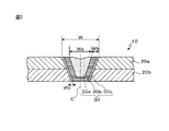
次に、本発明の接合継手について、図3を用いて説明する。図3は、接合部を含むように板厚方向に切断した本発明の接合継手の断面図を示している。 Next, the joint joint of this invention is demonstrated using FIG. FIG. 3 shows a cross-sectional view of the joint joint of the present invention cut in the thickness direction so as to include the joint portion.
本発明の接合継手10は、複数の金属板20a、20bを重ね合わせ、金属板20a側から金属板20a表面の一部の限られた領域内に光線を照射し、点状の接合部を形成して複数の金属板20a、20bを重ね接合したものである。金属板20a、20bは、点状の接合部の溶融凝固部30により接合されている。溶融凝固部30は、光線の照射側から溶融凝固部30を平面視したとき、中心部に溶融凝固したままの組織である再溶融凝固部30aと、凝固後に再加熱された凝固再加熱部30b、30cとにより構成されている。
以下、点状の接合部、及び、複数の金属板の順で詳細に説明する。
The joint joint 10 of the present invention overlaps a plurality of
Hereinafter, it demonstrates in detail in order of a dotted | punctate junction part and a some metal plate.
<点状の接合部>
点状の接合部は、複数の金属板20a、20bを重ね合わせ、光線の照射により溶融凝固した溶融凝固部30を有するものである。点状の接合部の溶融凝固部30は、複数の金属板20a、20bに跨って形成されていれば、複数の金属板を貫通していても、貫通していなくてもよい。
<Dotted joint>
The dotted joint has a melted and solidified
点状とは、光線の照射側から溶融凝固部を平面視したとき、溶融凝固部の外周輪郭が円形状又多角形状で、その輪郭の中心まで溶融凝固していることを意味する。円形状とは、光線の照射側から溶融凝固部を平面視したとき、溶融凝固部が円形や楕円形の場合以外に、直径の異なる半円や半楕円を組み合わせたものも含むものである。また、金属板に光線を渦巻状に、外周側から中心側又は中心側から外周側に向かって照射して形成した溶融凝固部の形状も点状に含まれる。 The dot shape means that when the molten and solidified portion is viewed in plan from the light irradiation side, the outer peripheral contour of the molten and solidified portion is circular or polygonal and melted and solidified to the center of the contour. The circular shape includes a combination of semi-circles and semi-ellipses having different diameters in addition to the case where the melt-solidified portion is circular or elliptical when the melt-solidified portion is viewed in plan from the light irradiation side. Moreover, the shape of the melt-solidified part formed by irradiating a metal plate with a light beam in a spiral shape from the outer peripheral side toward the central side or from the central side toward the outer peripheral side is also included in a dot shape.
点状の接合部の溶融凝固部30の幅W(光線の照射側から溶融凝固部を平面視したときの溶融凝固部の円相当径)は、継手強度等に応じて調整すればよく、特に限定されるものでないが、3〜12mmが例示される。好ましくは、4〜10mmである。 The width W (the equivalent circle diameter of the melt-solidified portion when the melt-solidified portion is viewed in plan from the light irradiation side) of the spot-like joined portion may be adjusted according to the joint strength, etc. Although not limited, 3-12 mm is illustrated. Preferably, it is 4-10 mm.
(再溶融凝固部)
再溶融凝固部30aは、点状の接合部の溶融凝固部30の内側に光線を再照射し、点状に溶融凝固させて得られる部分であり、溶融凝固したままの組織となっている。点状とは、光線の照射側から再溶融凝固部を平面視したとき、再溶融凝固部の外周輪郭が円形状又多角形状で、その輪郭の中心まで溶融凝固していることを意味する。円形状とは、光線の照射側から再溶融凝固部を平面視したとき、再溶融凝固部が円形や楕円形の場合以外に、直径の異なる半円や半楕円を組み合わせたものも含むものである。また、金属板に光線を渦巻状に、外周側から中心側又は中心側から外周側に向かって照射して形成した再溶融凝固部の形状も点状に含まれる。
(Remelt solidification part)
The remelted and solidified
再溶融凝固部30aは、光線の照射側から溶融凝固部を平面視したとき、溶融凝固部の円相当の中心を含み、溶融凝固部30の溶融境界を含まないように形成されている。ただし、光線の照射側から溶融凝固部を平面視したとき、溶融凝固部の円相当の中心と、再溶融凝固部30aの円相当の中心とは、一致する必要はない。
The remelted and solidified
また、再溶融凝固部30aは、接合継手10の板厚方向において、複数の金属板20a、20bに跨って形成されている。すなわち、図3に示すように、再溶融凝固部30aは、少なくとも複数の金属板に跨って形成されていれば、金属板20bを貫通してもしていなくてもどちらでもよい。
Further, the remelted and solidified
再溶融凝固部30aの幅Wa(光線の照射側から溶融凝固部を平面視したときの再溶融凝固部の円相当径)の上限は、特に限定されるものでなく、再溶融凝固部30aの周囲にある凝固再加熱部30b、30cの幅Wbとの関係で決められる。
The upper limit of the width Wa of the remelted and solidified
(凝固再加熱部)
凝固再加熱部30b、30cは、点状の接合部の溶融凝固部30に光線を再照射し、再溶融凝固部30aの周囲に溶融境界を含むように形成される部分であり、再溶融凝固部30aより軟化している部分を含むものである。再溶融凝固部30aに隣接した凝固再加熱部30bは、母材の融点以下Ac1点温度以上に再加熱された部位である。凝固再加熱部30cは、Ac1点温度以下に再加熱された部位であり、焼き戻された組織を有し、少なくとも金属板の重ね合わせ面近傍の溶融境界の周囲に形成されている。接合継手10に剥離方向に荷重が負荷されると、金属板の重ね合わせ面近傍の溶融境界に応力が集中し、破断に至るため、少なくとも凝固再加熱部30cの靱性を向上させる。
(Coagulation reheating part)
The
また、金属板の重ね合わせ面の溶融境界近傍の凝固再加熱部30cは、応力が集中し易いため、ビッカース硬さの平均値を、Hv390以下とし、また、再溶融凝固部30aのビッカース硬さの平均値よりHv70以上低くすることが好ましい。また、このような凝固再加熱部30cの幅Wcを、少なくとも0.5mmとすることで、溶融境界近傍の靱性を向上させることができる。凝固再加熱部30cの幅Wcを、少なくとも0.5mmとするためには、凝固再加熱部30b、30cの幅Wbとして、1.0〜3.0mmとすることが好ましい。
In addition, since the
再溶融凝固部30a、及び、凝固再加熱部30cのビッカース硬さの平均値の測定では、中心軸Cを含む板厚方向の断面において、金属板の重ね合わせ面と接する溶融凝固部30の溶融境界同士を結んだ線上を測定する。そして、再溶融凝固部30a、及び、凝固再加熱部30cにおいて、各部分の中央と両端近傍を含む3点以上等間隔でビッカース硬さを測定し、平均値を求める。具体的な測定条件の一例として、試験力0.3kgで、両端から0.15mmピッチで硬さを測定し、0.15mm、0.30mm、0.45mmでの硬さの平均値を求める。両端近傍とは、両端から幅の5〜10%の範囲である。また、金属板の重ね合わせ面が複数あるときは、それぞれの金属板の重ね合わせ面と接する溶融凝固部30の溶融境界同士を結んだ線上で測定する。なお、再溶融凝固部と凝固再加熱部とは、ミクロ組織の観察により、判別することができる。
In the measurement of the average value of the Vickers hardness of the remelted solidified
<複数の金属板>
次に、本発明の接合継手を構成する複数の金属板について説明する。
<Multiple metal plates>
Next, the several metal plate which comprises the joint joint of this invention is demonstrated.
(金属板の種類、組成)
金属板は、特に限定されるものでなく、種々の金属の板とすることができるが、鋼板とすることが好ましい。鋼板の成分組成は、特に限定されるものでなく、用途に応じた機械特性等が得られる成分組成の鋼板とすればよい。また、本発明の接合継手に炭素含有量を0.10質量%以上の高強度鋼板を適用すると、十字引張強さの向上が顕著であり、このような鋼板を対象とすることが好ましい。
(Type and composition of metal plate)
The metal plate is not particularly limited and may be a plate of various metals, but is preferably a steel plate. The component composition of the steel sheet is not particularly limited, and may be a steel sheet having a component composition that can provide mechanical properties and the like according to the application. Moreover, when a high-strength steel sheet having a carbon content of 0.10% by mass or more is applied to the joint joint of the present invention, the improvement in cross tensile strength is remarkable, and it is preferable to target such a steel sheet.
(金属板の板厚)
金属板の板厚は、特に限定されるものでなく、0.5〜3.2mmの範囲とすることができる。板厚が0.5mm未満であっても、接合部の継手強度の向上の効果は得られるが、継手強度が板厚に影響するので、接合継手全体の強度向上の効果が小さくなり、接合継手の適用範囲が限定される。また、板厚が3.2mm超であっても、接合部の継手強度の向上の効果は得られるが、部材の軽量化の観点から、接合継手の適用範囲が限定される。
(Metal plate thickness)
The plate | board thickness of a metal plate is not specifically limited, It can be set as the range of 0.5-3.2 mm. Even if the plate thickness is less than 0.5 mm, the effect of improving the joint strength of the joint can be obtained, but since the joint strength affects the plate thickness, the effect of improving the strength of the entire joint joint is reduced, and the joint joint is reduced. The scope of application is limited. Moreover, even if the plate thickness is over 3.2 mm, an effect of improving the joint strength of the joint portion can be obtained, but the application range of the joint joint is limited from the viewpoint of reducing the weight of the member.
(金属板の表面処理皮膜)
複数の金属板は、少なくとも接合箇所の両面又は片面に表面処理皮膜を形成した金属板を1枚以上含んでいてもよい。表面処理皮膜は、めっき皮膜を含むものであり、更に、塗装皮膜等を含むものとすることができる。めっき皮膜としては、例えば、亜鉛めっき、アルミニウムめっき、亜鉛・ニッケルめっき、亜鉛・鉄めっき、亜鉛・アルミニウム・マグネシウム系めっき等であり、めっきの製造方法としては、溶融めっき、電気めっき等である。またホットスタンプされた亜鉛めっきやアルミニウムのめっきでもよい。
(Surface treatment film of metal plate)
The plurality of metal plates may include one or more metal plates in which a surface treatment film is formed on both surfaces or one surface of at least a joining portion. The surface treatment film includes a plating film, and may further include a coating film or the like. Examples of the plating film include zinc plating, aluminum plating, zinc / nickel plating, zinc / iron plating, and zinc / aluminum / magnesium plating. The plating production method includes hot dipping and electroplating. Hot stamped zinc plating or aluminum plating may also be used.
(金属板の形態)
金属板の形態は、少なくとも接合継手を形成する部分が板状であればよく、全体が板でなくてもよい。例えば、断面ハット形の特定の形状にプレス成型された部材のフランジ部、パイプの平面部などを含むものである。重ね合わせる金属板の枚数は、2枚に限らず、3枚以上としてもよい。また、各金属板の、種類、成分組成及び板厚は、全て同じとしても、相互に異なっていてもよい。また、別々の金属板から構成されるものに限定されず、1枚の金属板を管状などの所定の形状に成形して、端部を重ね合わせたものの重ね接合継手であってもよい。
(Metal plate form)
As for the form of the metal plate, it suffices that at least the portion forming the joint joint is plate-like, and the whole may not be a plate. For example, it includes a flange portion of a member press-molded into a specific shape having a hat-shaped cross section, a flat portion of a pipe, and the like. The number of metal plates to be superimposed is not limited to two and may be three or more. Further, the types, component compositions, and plate thicknesses of the respective metal plates may all be the same or different from each other. Moreover, it is not limited to what is comprised from a separate metal plate, The lap | joint joint of what formed one metal plate in predetermined shapes, such as a tubular shape, and overlap | superposed the edge part may be sufficient.
以下、これに限定されるものではないが、自動車での重ね接合継手の例を示す。
Aピラーの場合、270〜340MPa級の合金化溶融亜鉛めっき鋼板と、590〜1800MPa級非めっき鋼板もしくはホットスタンプ鋼板と、590〜1800MPa級非めっき鋼板もしくはホットスタンプ鋼板の3枚重ねの組み合わせでの重ね接合継手が例示される。
Hereinafter, although not limited thereto, an example of a lap joint in an automobile will be shown.
In the case of A-pillar, a combination of 270 to 340 MPa class galvannealed steel sheet, 590 to 1800 MPa class non-plated steel sheet or hot stamped steel sheet, and 590 to 1800 MPa class non-plated steel sheet or hot stamped steel sheet A lap joint is illustrated.
Bピラーの場合、引張強さが270〜340MPa級の合金化溶融亜鉛めっき鋼板と、590〜1800MPa級非めっき鋼板もしくはホットスタンプ鋼板と、440〜980MPa級非めっき鋼板の3枚重ねの組み合わせでの重ね接合継手が例示される。 In the case of the B pillar, a combination of three layers of an alloyed hot-dip galvanized steel sheet having a tensile strength of 270 to 340 MPa, a 590 to 1800 MPa class non-plated steel sheet or a hot stamped steel sheet, and a 440 to 980 MPa class non-plated steel sheet A lap joint is illustrated.
サイドシルの場合、270〜340MPa級の合金化溶融亜鉛めっき鋼板と、590〜1800MPa級合金化溶融亜鉛めっき鋼板と、590〜1800MPa級合金化溶融亜鉛めっき鋼板の3枚重ねの組み合わせでの重ね接合継手が例示される。 In the case of a side sill, a lap-jointed joint in a combination of three layers of a 270 to 340 MPa class galvannealed steel sheet, a 590 to 1800 MPa class galvannealed steel sheet, and a 590 to 1800 MPa class galvannealed steel sheet Is exemplified.
フロアメンバーの場合、270〜590MPa級の合金化溶融亜鉛めっき鋼板のフロアパネルと、440〜1800MPa級非めっき鋼板もしくは合金化溶融亜鉛めっき鋼板のフロアメンバーとの2枚重ねでの組み合わせでの重ね接合継手が例示される。 In the case of a floor member, lap joining in a combination of two layers of a 270-590 MPa class alloyed hot dip galvanized steel floor panel and a 440-1800 MPa class non-plated steel sheet or an alloyed hot dip galvanized steel floor member A joint is illustrated.
次に、本発明の重ね接合継手の製造方法(以下、「本発明の製法」という)について説明する。
本発明の製法は、
(a)複数の金属板を重ね合わせ、光線を照射し、金属板表面側から平面視したとき、外側輪郭が略円形状で、その中心まで溶融凝固した点状の接合部を形成すること、及び、
(b)点状の接合部の内側に光線を再照射し、光線の照射側から溶融凝固部を平面視したとき、外側輪郭が略円形状で、その中心まで再溶融凝固した形状に再溶融凝固させるともに、再溶融凝固部より軟化するように溶融境界を再加熱することを含むものである。
Next, a method for producing a lap joint according to the present invention (hereinafter referred to as “the production method of the present invention”) will be described.
The production method of the present invention comprises:
(A) When a plurality of metal plates are overlapped, irradiated with light rays, and viewed in plan from the metal plate surface side, the outer contour is substantially circular, forming a point-like joint melted and solidified to the center; as well as,
(B) Re-irradiate the inside of the dotted joint with light rays, and when the molten and solidified portion is viewed in plan from the light irradiation side, the outer contour is substantially circular and re-melted into a shape that has been re-melted and solidified to the center. It includes solidifying and reheating the melting boundary so as to soften from the remelted solidified portion.
まず、(a)複数の金属板を重ね合わせ、光線を照射し、金属板表面側から平面視したとき、外側輪郭が略円形状で、その中心まで溶融凝固した点状の接合部を形成することについて、図4を用いて説明する。 First, (a) when a plurality of metal plates are overlapped, irradiated with light, and viewed in plan from the metal plate surface side, the outer contour is substantially circular, and a point-like joint is formed that melts and solidifies to the center. This will be described with reference to FIG.
図4は、点状の接合部の形成の概要を示す斜視図である。図4(a)は、異なる照射直径で光線を照射する概要を示し、図4(b)は、集光面積を広くして光線を照射する概要を示し、図4(c)は、形成された点状の接合部を示す。 FIG. 4 is a perspective view showing an outline of the formation of the dotted joint. FIG. 4 (a) shows an outline of irradiating light rays with different irradiation diameters, FIG. 4 (b) shows an outline of irradiating light rays with a wide condensing area, and FIG. 4 (c) is formed. A dotted joint is shown.
図4(a)には、光線50を照射する方法の一例を示しており、異なる照射直径で光線50を照射するものである。この図には、光線50の照射予定箇所60aを点線で示しており、照射直径の異なる3つの照射予定箇所60aが示されている。
FIG. 4A shows an example of a method of irradiating the
点状の接合部の形成では、まず、複数の金属板20a、20bを重ね合わせ、一方の金属板20a側から光線50を照射して接合を行う。光線50の照射では、光線50の照射側から照射予定箇所60aを平面視したとき、白抜き矢印で示すように、略円状に光線を走査する。その際に、光線50の照射を、外側の照射予定箇所60aに行い、その後、内側の照射予定箇所60aに行っても、内側の照射予定箇所60aに行い、その後、外側の照射予定箇所60aに行ってもよい。光線の走査方向は、特に限定されるものでなく、時計回り、反時計回りのいずれでもよい。
In the formation of the dotted joint, first, the plurality of
また、光線50の照射側からの照射予定箇所60aを平面視した場合、光線50の照射予定箇所60aの外周形状を円としているが、楕円状、多角形状、直径の異なる半円や半楕円を組み合わせた形状、渦巻状の形状としてもよい。光線50の照射予定箇所60aを渦巻状の形状とした場合、光線50の照射は、渦巻状の照射予定箇所60bの外側の端部から、内側の端部に向かって、又は、渦巻状の照射予定箇所60bの内側の端部から、外側の端部に向かって、渦巻状に光線を走査して行う。渦巻の方向は、特に限定されるものでなく、時計回り、反時計回りのいずれでもよい。
In addition, when the
図4(a)では、直径の異なる3つの照射予定箇所を例示したが、光線の焦点面積や、点状の接合部の接合面積に応じて、直径の異なる照射予定箇所の数を増減させることができる。 In FIG. 4 (a), three irradiation planned places with different diameters are illustrated, but the number of irradiation planned spots with different diameters may be increased or decreased according to the focal area of the light beam or the bonding area of the dotted joint. Can do.
図4(b)には、光線50を照射する方法の他の例を示しており、集光面積を広くして光線50を照射するものである。この図には、光線50の照射予定箇所60bを点線で示している。そして、光線50の照射は、光線の集光面積を広くして、1回で行われる。
FIG. 4B shows another example of the method of irradiating the
図4(a)または図4(b)に示すように光線50を照射することで、溶融した溶融部が外側から中心側に凝固し、図4(c)に示すように点状の接合部の溶融凝固部30を形成できる。
As shown in FIG. 4 (a) or 4 (b), by irradiating the
また、複数の金属板に、表面処理皮膜を形成した金属板を1枚以上用いる場合、光線50の照射を、外側の照射予定箇所60aに行い、その後、内側の照射予定箇所60aに行うことが好ましい。これにより、接合部内に欠陥を生じさせる気体となった皮膜を、溶融部の中心付近に集め、攪拌除去することが容易となる。なお、光線50の照射を、内側の照射予定箇所60aに行い、その後、外側の照射予定箇所60aに行っても、光線50の集光面積を広くして行っても、気体となった皮膜を溶融部から除去することができるため、これらの光線の照射方法を採用することを排除するものでない。
Moreover, when using one or more metal plates on which a surface treatment film is formed on a plurality of metal plates, the irradiation of the
次に、(b)点状の接合部の内側に光線を再照射し、光線の照射側から溶融凝固部を平面視したとき、外側輪郭が略円形状で、その中心まで再溶融凝固した形状(点状)に再溶融凝固させるともに、再溶融凝固部より軟化するように溶融境界を再加熱することについて説明する。 Next, (b) when the light beam is re-irradiated inside the dotted joint, and when the melt-solidified portion is viewed in plan from the light-irradiated side, the outer contour is substantially circular, and the shape is re-melt-solidified to the center. A description will be given of re-melting and solidifying (dots) and reheating the melting boundary so as to soften from the re-melting and solidifying part.
点状の接合部の熱処理では、図4で示す方法等により得られた点状の接合部の溶融凝固部30の温度が所定温度以下、例えば、鋼板ではMs点−50℃(Ms点:マルテンサイト変態開始温度)以下となるまで待機し、その後に、金属板20a側から溶融凝固部30の内側に光線50を照射して行う。内側とは、溶融凝固部30の溶融境界を除く溶融凝固部30内をいう。
In the heat treatment of the spot-like joint, the temperature of the melt-solidified
溶融凝固部30の温度をMs点−50℃以下とすると、鋼板中に一定量以上のマルテンサイトが生成されるため、点状の接合部の溶融凝固部30を熱処理することで、このマルテンサイトが焼戻されて軟化し、継手強度が向上する。また、点状の接合部の溶融凝固部30の熱処理の開始するときの溶融凝固部30の温度の下限は、特に限定されないが、Ms点−250℃以下とするのが好ましい。Ms点−250℃で、一般の鋼板はマルテンサイト変態を終了するからである。
If the temperature of the melt-solidified
次に、点状の接合部の熱処理における光線50の照射のうち、光線50の走査について、図5を用いて説明する。
図5は、点状の接合部の熱処理の概要を示す斜視図である。図5(a)は、異なる照射直径で光線を照射する概要を示し、図5(b)は、集光面積を広くして光線を照射する概要を示し、図5(c)は、再溶融凝固部と凝固再加熱部とを有する点状の接合部を示す。
Next, scanning of the
FIG. 5 is a perspective view showing an outline of the heat treatment of the dotted joint. FIG. 5 (a) shows an outline of irradiating light beams with different irradiation diameters, FIG. 5 (b) shows an outline of irradiating light beams with a wide condensing area, and FIG. 5 (c) shows remelting. The point-like junction which has a solidification part and a solidification reheating part is shown.
図5(a)には、再溶融予定箇所に光線50を照射する方法の一例を示しており、異なる照射直径で光線を照射するものである。この図には、光線50の照射予定箇所70aを点線で示しており、溶融凝固部30の内側に、照射直径の異なる2つの照射予定箇所70aが示されている。
FIG. 5A shows an example of a method of irradiating the re-melted portion with the
光線50の照射では、白抜き矢印で示すように略円状に光線を走査する。その際に、光線50の照射を、内側の照射予定箇所70aに行い、その後、外側の照射予定箇所70aに行っても、外側の照射予定箇所70aに行い、その後、内側の照射予定箇所70aに行ってもよい。光線の走査方向は、特に限定されるものでなく、時計回り、反時計回りのいずれでもよい。
In the irradiation of the
光線50の照射予定箇所70aは、光線50の照射側から溶融凝固部30を平面視したとき、溶融凝固部30の円相当中心を含む点状に再溶融され、溶融凝固部30の溶融境界が焼き戻されるように設定される。
When the molten solidified
また、光線50の照射側から接合部を平面視した場合、光線50の照射予定箇所70aの外周形状を円としているが、楕円状、多角形状、直径の異なる半円や半楕円を組み合わせた形状、渦巻状の形状としてもよい。また、直径の異なる2つの照射予定箇所を例示したが、光線の焦点面積や、点状の接合部の溶融凝固部の面積に応じて、直径の異なる照射予定箇所の数を増減させることができる。
Further, when the joint portion is viewed in plan from the irradiation side of the
図5(b)には、再溶融予定箇所に光線50を照射する方法の他の例を示しており、集光面積を広くして光線50を照射するものである。この図には、溶融凝固部30の内側に、光線50の照射予定箇所80bを点線で示している。そして、光線50の照射は、光線の集光面積を広くして、1回で行われる。この例においても、光線50の照射予定箇所80bは、光線50の照射側から溶融凝固部30を平面視したとき、溶融凝固部30の円相当中心を含む点状に再溶融され、溶融凝固部30の溶融境界が焼き戻されるように設定される。
FIG. 5B shows another example of the method of irradiating the re-melting planned portion with the
図5(a)、図5(b)に示すように光線50を照射することで、図5(c)に示すように、光線50の照射側から溶融凝固部30を平面視したとき、当該溶融凝固部の円相当中心を含む点状に再溶融凝固部30aが形成され、その周囲に凝固再加熱部30b、30cが形成される。そして、溶融境界を含む凝固再加熱部30cが焼き戻され、靱性が向上する。
By irradiating the
また、点状の接合部の形成、及び、点状の接合部の溶融境界の熱処理において、光線の照射方法は、同じ照射方法でも、異なる照射方法でもよい。例えば、異なる照射直径で光線を照射して、点状の接合部を形成し、異なる照射直径で光線を照射して、点状の接合部の溶融境界を熱処理しても、集光面積を広くして光線を照射して、点状の接合部の形成し、異なる照射直径で光線を照射して、点状の接合部の溶融境界を熱処理してもよい。 Further, in the formation of the dotted joint and the heat treatment at the melting boundary of the dotted joint, the light irradiation method may be the same irradiation method or different irradiation methods. For example, even if a light beam is irradiated with a different irradiation diameter to form a spot-like joint, and a light beam is irradiated with a different irradiation diameter to heat-treat the melting boundary of the spot-like joint, the condensing area is widened. Then, a light beam may be irradiated to form a dotted joint, and a light beam may be irradiated with a different irradiation diameter to heat-treat the melting boundary of the dotted joint.
次に、光線50の照射のうち、凝固再加熱部30b、30cの加熱温度について説明する。
点状の接合部の溶融凝固部30のうち、少なくとも金属板20a、20bの重ね合わせ面近傍の溶融境界から0.5mmの範囲の領域が、焼き戻されるように(凝固再加熱部30cが得られるように)再加熱するとよい。
Next, of the irradiation with the
Of the melt-solidified
重ね合わせ面近傍の溶融境界から0.5mmの範囲の領域を焼き戻すには、この範囲の最高到達温度がAc1点以下の所定の温度(例えば、500℃以上700℃以下)となる条件で、光線50を溶融凝固部30の内側に照射する。凝固再加熱部30cの温度は、鋼板表面で測定した温度を代表値として用いることができる。温度は、放射温度計や熱電対を用いて測定することができる。
In order to temper a region in the range of 0.5 mm from the melting boundary in the vicinity of the overlapping surface, the maximum attained temperature in this range is a predetermined temperature below the Ac1 point (for example, 500 ° C. or more and 700 ° C. or less), A
このような温度とするには、予め、再溶融予定箇所(光線の照射予定箇所)の円相当直径又は形成される凝固再加熱部の幅Wbと、光線の再照射中の前記範囲の温度との関係や、光線の再照射時間と前記範囲の温度との関係等を調査しておき、再溶融予定箇所(光線の照射予定箇所)の円相当直径、凝固再加熱部の幅Wb、光線の再照射時間等を調整することで行うことができる。また、凝固再加熱部30cを500℃以上700℃以下とするには、凝固再加熱部の幅Wbを1.0〜3.0mmとなるように光線の照射を調整することが例示される。好ましくは、1.5〜2.5mmである。
In order to obtain such a temperature, the equivalent circle diameter of the remelting point (scheduled light irradiation point) or the width Wb of the solidified reheating part to be formed, and the temperature in the above range during the reirradiation of the light beam, , The relationship between the re-irradiation time of the light beam and the temperature in the above range, and the like, the equivalent circle diameter of the re-melting point (light beam irradiation point), the width Wb of the solidification reheating part, This can be done by adjusting the re-irradiation time or the like. Further, in order to set the
次に、点状の接合部の形成、及び、点状の接合部の熱処理で使用する光線について説明する。光線にはレーザを用いるのが一般的であり、その種類は、特に限定されるものでないが、リモート接合装置とすることが好ましい。リモート接合装置は、ロボットアームの先端に取り付けたガルバノミラーにより、光線を接合打点の間を高速で移動させるものであり、接合の作業時間の大幅な短縮が可能になる。また、発振器としては、気体励起タイプや固体励起タイプ、半導体タイプなどを用いることができる。 Next, a description will be given of the light rays used in the formation of the dotted joint and the heat treatment of the dotted joint. A laser is generally used for the light beam, and the type is not particularly limited, but a remote bonding apparatus is preferable. The remote bonding apparatus moves a light beam between bonding points at high speed by a galvanometer mirror attached to the tip of a robot arm, and can greatly reduce the work time of bonding. As the oscillator, a gas excitation type, a solid excitation type, a semiconductor type, or the like can be used.
また、接合の条件は、従来の条件を採用することができる。例えば、出力2〜30kW、集光面の光線径0.1〜8.0mm、接合速度0.1〜60m/minの接合条件で行うことができる。 Moreover, the conventional conditions can be employ | adopted for the conditions of joining. For example, it can be performed under the joining conditions of an output of 2 to 30 kW, a light beam diameter of the condensing surface of 0.1 to 8.0 mm, and a joining speed of 0.1 to 60 m / min.
また、自動車の組み立ては、複数の接合工程からなるが、1つの工程内で本発明の製法を実施する場合、1つ1つの接合点に対して、光線照射による接合と再溶融を実施してもよいが、Ms点−250℃以下までの冷却の待ち時間を低減するため、より好適には、光線照射により複数の溶融接合を実施し、その後、光線照射により複数の再溶融を実施するとことが好ましい。また複数の接合工程で本発明の製法を実施する場合、光線照射による溶融接合工程と、光線照射による再溶融工程を別々の工程とすることで、冷却の待ち時間を無くすことができる。 In addition, the assembly of automobiles consists of a plurality of joining processes, but when the manufacturing method of the present invention is carried out within one process, the joining and remelting by light irradiation is carried out for each joining point. However, in order to reduce the waiting time for cooling to an Ms point of −250 ° C. or lower, more preferably, a plurality of melt bonding is performed by light irradiation, and then a plurality of remelting is performed by light irradiation. Is preferred. Moreover, when implementing the manufacturing method of this invention in a some joining process, the waiting time of cooling can be eliminated by making the fusion | melting joining process by light irradiation, and the remelting process by light irradiation into a separate process.
次に、本発明の実施例について説明するが、実施例での条件は、本発明の実施可能性及び効果を確認するために採用した一条件例であり、本発明は、この一条件例に限定されるものではない。本発明は、本発明の要旨を逸脱せず、本発明の目的を達成する限りにおいて、種々の条件を採用し得るものである。 Next, examples of the present invention will be described. The conditions in the examples are one example of conditions used for confirming the feasibility and effects of the present invention, and the present invention is based on this one example of conditions. It is not limited. The present invention can adopt various conditions as long as the object of the present invention is achieved without departing from the gist of the present invention.
表1に、被接合部材とする鋼板を示す。 Table 1 shows steel sheets to be joined.

表1に示す、同種の鋼板を2枚重ね合わせて、ガルバノミラーを有するリモート接合装置を用い、ファイバーレーザにより接合を行い、点状の接合部を有する試験片を作成した。表2に、点状の接合部の形成条件を示す。光線径は、集光面での光線の直径である。 Two steel plates of the same type shown in Table 1 were overlapped and joined by a fiber laser using a remote joining device having a galvanometer mirror, to create a test piece having a dotted joint. Table 2 shows the conditions for forming the dotted joint. The light beam diameter is the diameter of the light beam on the condensing surface.
次に、各試験片の点状の接合部の熱処理を行った。この熱処理では、光線の照射側から溶融凝固部を平面視したとき、溶融凝固部と再溶融凝固部の中心が一致するようにし、試験片を貫通するように再溶融凝固部を形成して行った。表3に、点状のレーザ接合部の熱処理条件を示す。光線径は、集光面での光線の直径である。なお、熱処理では、点状の接合部の形成と同じリモート接合装置を用いた。 Next, heat treatment was performed on the dotted joints of each test piece. This heat treatment is carried out by forming the remelted and solidified part so that the center of the melted and solidified part and the remelted and solidified part coincide with each other when the melted and solidified part is viewed in plan from the light irradiation side. It was. Table 3 shows the heat treatment conditions for the spot-like laser junction. The light beam diameter is the diameter of the light beam on the condensing surface. In the heat treatment, the same remote bonding apparatus as that for forming the dotted joints was used.
表4に、熱処理後の試験片について、凝固再加熱部の幅Wb、再溶融凝固部の平均ビッカース硬さA(引け巣は除く)、溶融凝固部の溶融境界から0.5mmの範囲の平均ビッカース硬さB、平均ビッカース硬さAとBの差、十字引張強さ(CTS)について示す。 Table 4 shows the test piece after the heat treatment, the width Wb of the solidification reheated part, the average Vickers hardness A (excluding the shrinkage nest) of the remelted solidified part, and the average of 0.5 mm from the melting boundary of the molten solidified part. The Vickers hardness B, the difference between the average Vickers hardness A and B, and the cross tensile strength (CTS) are shown.
CTSは、JIS Z3137にスポット接合の強度試験方法として記載されている方法を採用した。また、接合後、点状接合部の中心を通り、板面に垂直に鋼板を切断し研磨し、引け巣の大きさを観察するととともに、ビッカース硬さを測定した。なお、比較例1、5、14のビッカース硬さAは、溶融凝固部の中心部の平均ビッカース硬さである。 For CTS, a method described in JIS Z3137 as a strength test method for spot bonding was adopted. Further, after joining, the steel sheet was cut and polished perpendicularly to the plate surface through the center of the dotted joint, and the size of the shrinkage nest was observed, and the Vickers hardness was measured. The Vickers hardness A of Comparative Examples 1, 5, and 14 is the average Vickers hardness at the center of the melt-solidified portion.
No.2〜4、6〜8、10〜13は、点状の接合部に熱処理を行い、本発明の接合継手で規定する構成を満足するため、溶融凝固部の溶融境界から0.5mmの範囲の靱性が向上し、十字引張強さ(CTS)が高い。 No. 2 to 4, 6 to 8, and 10 to 13 are heat-treated on the dotted joints, and satisfy the configuration defined by the joint joint of the present invention. Toughness is improved and cross tensile strength (CTS) is high.
それに対して、No.1、No.5、及び、No.14は、点状の接合部に熱処理を行っていないため、溶融凝固部の溶融境界の靱性が向上せず、十字引張強さ(CTS)が低い。また、No.9は、溶融凝固部の全部に熱処理を行ったため、溶融凝固部の溶融境界の靱性が向上せず、十字引張強さ(CTS)が低い。 In contrast, no. 1, no. 5 and No. In No. 14, since the heat treatment is not performed on the spot-like joint portion, the toughness of the melt boundary of the melt-solidified portion is not improved, and the cross tensile strength (CTS) is low. No. In No. 9, since the entire melt-solidified part was heat-treated, the toughness of the melt boundary of the melt-solidified part was not improved, and the cross tensile strength (CTS) was low.
本発明によれば、点状の接合部の溶融境界近傍に、靱性に優れる凝固再加熱部を設けたので、重ね接合継手の継手強度、特に、十字引張強さ(CTS)を向上させることができ、接合継手の信頼性を向上させることができる。そして、本発明の接合継手を自動車部品に適用することで、自動車部品の信頼性を向上させることができる。よって、本発明は、産業上の利用可能性が高いものである。 According to the present invention, since the solidification reheat part having excellent toughness is provided in the vicinity of the melting boundary of the dotted joint, the joint strength of the lap joint, particularly the cross tensile strength (CTS) can be improved. It is possible to improve the reliability of the joint joint. And the reliability of a motor vehicle component can be improved by applying the joint joint of this invention to a motor vehicle component. Therefore, the present invention has high industrial applicability.
1 接合継手
2a、2b 金属板
3 点状の接合部の溶融凝固部
3a 再溶融凝固部
3b 凝固再加熱部
10 接合継手
20a、20b 金属板
30 点状の接合部の溶融凝固部
30a 再溶融凝固部
30b 凝固再加熱部
30c 凝固再加熱部
50 光線
60a、60b 照射予定箇所
70a、70b 照射予定箇所
X 板厚方向のビッカース硬さの測定位置
L1 金属板表面と平行方向のビッカース硬さの測定範囲
L2 溶融凝固部のビッカース硬さの測定範囲
L3 再溶融凝固部のビッカース硬さの測定範囲
C 中心軸
W 溶融凝固部の幅
Wa 再溶融凝固部の幅
Wb 凝固再加熱部の幅
Wc 溶融境界近傍の凝固再加熱部の幅
DESCRIPTION OF
Claims (6)
前記点状の接合部は、前記複数の金属板に跨る溶融凝固部を有し、
前記溶融凝固部は、再溶融凝固部と、凝固再加熱部とを有し、
前記再溶融凝固部は、前記溶融凝固部を平面視したとき、当該溶融凝固部の中心を含む点状で、前記複数の金属板に跨っており、
前記凝固再加熱部は、前記再溶融凝固部の周囲に位置し、前記点状の接合部の溶融境界を含んでおり、前記再溶融凝固部より軟化している
ことを特徴とする重ね接合継手。 In a lap joint with a plurality of metal plates stacked and having a dotted joint,
The dotted joint has a melt-solidified part straddling the plurality of metal plates,
The molten and solidified part has a remelted and solidified part and a solidified and reheated part,
The remelted and solidified part is a dot including the center of the melted and solidified part when the melted and solidified part is viewed in plan, and straddles the plurality of metal plates,
The lap joint joint is characterized in that the solidification reheating part is located around the remelt solidification part, includes a melting boundary of the dotted joint, and is softer than the remelt solidification part .
重ね合わされた一方の金属板に高いパワー密度を有する光線を照射して、前記複数の金属板に跨って点状に溶融凝固した溶融凝固部を有する点状の接合部を形成し、
前記高いパワー密度を有する光線の照射側から前記溶融凝固部を平面視したとき、当該溶融凝固部の内側に前記高いパワー密度を有する光線を再照射し、当該溶融凝固部の円相当中心を含む点状に、前記複数の金属板に跨って再溶融凝固させて再溶融凝固部を形成し、更に、当該再溶融凝固部の周囲に前記点状の接合部の溶融境界を含む凝固再加熱部を形成するとともに、その際の再加熱条件を調整して前記凝固再加熱部を前記再溶融凝固部より軟化させることを特徴とする重ね接合継手の製造方法。 In the method of manufacturing a lap joint where a plurality of metal plates are overlapped and bonded by irradiating a light beam having a high power density,
Irradiating a light beam having a high power density to one of the superimposed metal plates to form a point-like joint having a melt-solidified portion melted and solidified in a point-like manner across the plurality of metal plates,
When the molten and solidified portion is viewed in plan from the irradiation side of the light beam having the high power density, the light beam having the high power density is re-irradiated inside the molten and solidified portion, and includes the circle-equivalent center of the molten and solidified portion. A solidified and reheated portion that is re-melted and solidified across the plurality of metal plates to form a remelted and solidified portion, and further includes a melting boundary of the dotted joint around the remelted and solidified portion. And a reheat condition at that time is adjusted to soften the solidified reheated part from the remelted solidified part.
Applications Claiming Priority (2)
| Application Number | Priority Date | Filing Date | Title |
|---|---|---|---|
| JP2015178433 | 2015-09-10 | ||
| JP2015178433 | 2015-09-10 |
Publications (2)
| Publication Number | Publication Date |
|---|---|
| JP2017052006A true JP2017052006A (en) | 2017-03-16 |
| JP6786977B2 JP6786977B2 (en) | 2020-11-18 |
Family
ID=58320205
Family Applications (1)
| Application Number | Title | Priority Date | Filing Date |
|---|---|---|---|
| JP2016177077A Active JP6786977B2 (en) | 2015-09-10 | 2016-09-09 | Laminated joint and its manufacturing method |
Country Status (1)
| Country | Link |
|---|---|
| JP (1) | JP6786977B2 (en) |
Cited By (3)
| Publication number | Priority date | Publication date | Assignee | Title |
|---|---|---|---|---|
| CN108941912A (en) * | 2017-05-22 | 2018-12-07 | 日本梅克特隆株式会社 | The joint construction and sheet metal of sheet metal and substrate and the welding method of substrate |
| WO2019198725A1 (en) * | 2018-04-09 | 2019-10-17 | 日本製鉄株式会社 | Spot welding joint, automobile frame part provided with spot welding joint, and method for producing spot welding joint |
| WO2020003950A1 (en) | 2018-06-27 | 2020-01-02 | Smc株式会社 | Butt welded joint of steel material and method for manufacturing same |
Citations (5)
| Publication number | Priority date | Publication date | Assignee | Title |
|---|---|---|---|---|
| WO2001017722A1 (en) * | 1999-09-03 | 2001-03-15 | Renault | Method and device for welding sheet metal |
| JP2002160083A (en) * | 2000-11-29 | 2002-06-04 | Nippon Steel Corp | Method of laser welding for overlapped zinc steel plates |
| JP2007160326A (en) * | 2005-12-12 | 2007-06-28 | Miyachi Technos Corp | Method of laser welding |
| JP2012240083A (en) * | 2011-05-19 | 2012-12-10 | Nippon Steel Corp | Method for manufacturing steel sheet welded part excellent in delayed fracture resistance and steel structure having welded part |
| JP2014147962A (en) * | 2013-02-01 | 2014-08-21 | Olympus Medical Systems Corp | Member joining method, member-joined structure and joined pipe |
-
2016
- 2016-09-09 JP JP2016177077A patent/JP6786977B2/en active Active
Patent Citations (5)
| Publication number | Priority date | Publication date | Assignee | Title |
|---|---|---|---|---|
| WO2001017722A1 (en) * | 1999-09-03 | 2001-03-15 | Renault | Method and device for welding sheet metal |
| JP2002160083A (en) * | 2000-11-29 | 2002-06-04 | Nippon Steel Corp | Method of laser welding for overlapped zinc steel plates |
| JP2007160326A (en) * | 2005-12-12 | 2007-06-28 | Miyachi Technos Corp | Method of laser welding |
| JP2012240083A (en) * | 2011-05-19 | 2012-12-10 | Nippon Steel Corp | Method for manufacturing steel sheet welded part excellent in delayed fracture resistance and steel structure having welded part |
| JP2014147962A (en) * | 2013-02-01 | 2014-08-21 | Olympus Medical Systems Corp | Member joining method, member-joined structure and joined pipe |
Cited By (8)
| Publication number | Priority date | Publication date | Assignee | Title |
|---|---|---|---|---|
| CN108941912A (en) * | 2017-05-22 | 2018-12-07 | 日本梅克特隆株式会社 | The joint construction and sheet metal of sheet metal and substrate and the welding method of substrate |
| US11225990B2 (en) | 2017-05-22 | 2022-01-18 | Nippon Mektron, Ltd. | Joining structure of thin metal plate and base material, and welding method of thin metal plate and base material |
| CN108941912B (en) * | 2017-05-22 | 2022-05-03 | 日本梅克特隆株式会社 | Printed circuit board joining structure and printed circuit board soldering method |
| WO2019198725A1 (en) * | 2018-04-09 | 2019-10-17 | 日本製鉄株式会社 | Spot welding joint, automobile frame part provided with spot welding joint, and method for producing spot welding joint |
| JPWO2019198725A1 (en) * | 2018-04-09 | 2020-12-17 | 日本製鉄株式会社 | Manufacturing method of spot welded joints, automobile frame parts including spot welded joints, and spot welded joints |
| JP7151762B2 (en) | 2018-04-09 | 2022-10-12 | 日本製鉄株式会社 | SPOT WELD JOINTS, MOTOR VEHICLE STRUCTURE COMPONENTS WITH SPOT WELD JOINTS, AND METHOD FOR MANUFACTURING THE SPOT WELD JOINTS |
| WO2020003950A1 (en) | 2018-06-27 | 2020-01-02 | Smc株式会社 | Butt welded joint of steel material and method for manufacturing same |
| US20210260699A1 (en) * | 2018-06-27 | 2021-08-26 | Smc Corporation | Butt welded joint of steel material and method for manufacturing same |
Also Published As
| Publication number | Publication date |
|---|---|
| JP6786977B2 (en) | 2020-11-18 |
Similar Documents
| Publication | Publication Date | Title |
|---|---|---|
| JP6430070B2 (en) | Laser welding method for producing semi-finished sheet metal products made of hardenable steel and having an aluminum or aluminum-silicon coating | |
| KR101463702B1 (en) | Laser welding method | |
| US10589380B2 (en) | Lap welding method, lap joint, production method of lap joint, and an automobile part | |
| CA2939839C (en) | Method for laser welding one or more workpieces made of hardenable steel in a butt joint | |
| JP6690540B2 (en) | Laser welded joint and laser welding method | |
| KR20180019214A (en) | Fillet arc welded joint and manufacturing method thereof | |
| JP6443319B2 (en) | Lap laser spot welded joint and method of manufacturing the welded joint | |
| JP6786977B2 (en) | Laminated joint and its manufacturing method | |
| JP6379819B2 (en) | Lap welding member, lap resistance seam welding method of lap welding member, and lap welding member for automobile having lap welding part | |
| KR102398807B1 (en) | Lap laser welded joint, manufacturing method of lap laser welded joint and skeletal parts for automobiles | |
| KR102285572B1 (en) | Steel sheet, tailored blank, hot press-formed product, steel pipe, hollow quenching molded product, steel sheet manufacturing method, tailored blank manufacturing method, hot press-formed product manufacturing method, steel pipe manufacturing method, and hollow quenching molded product manufacturing method | |
| JP6798359B2 (en) | Laminated joint and its manufacturing method | |
| JP2017052005A (en) | Lap joint coupler and method for manufacturing same | |
| JP6885523B2 (en) | Manufacturing method of spot welded joints and spot welded joints | |
| JP6866691B2 (en) | Laminated joint and its manufacturing method | |
| JP6583657B1 (en) | Lap laser welded joint, manufacturing method thereof, and structural member for automobile body | |
| JP7151762B2 (en) | SPOT WELD JOINTS, MOTOR VEHICLE STRUCTURE COMPONENTS WITH SPOT WELD JOINTS, AND METHOD FOR MANUFACTURING THE SPOT WELD JOINTS | |
| JP2019188407A (en) | Laser welded joint and method for production thereof | |
| JP6852797B2 (en) | Laminated laser welded joints, manufacturing methods of lap laser welded joints and skeleton parts for automobiles |
Legal Events
| Date | Code | Title | Description |
|---|---|---|---|
| A621 | Written request for application examination |
Free format text: JAPANESE INTERMEDIATE CODE: A621 Effective date: 20190415 |
|
| A131 | Notification of reasons for refusal |
Free format text: JAPANESE INTERMEDIATE CODE: A131 Effective date: 20200310 |
|
| A977 | Report on retrieval |
Free format text: JAPANESE INTERMEDIATE CODE: A971007 Effective date: 20200311 |
|
| A521 | Request for written amendment filed |
Free format text: JAPANESE INTERMEDIATE CODE: A523 Effective date: 20200420 |
|
| TRDD | Decision of grant or rejection written | ||
| A01 | Written decision to grant a patent or to grant a registration (utility model) |
Free format text: JAPANESE INTERMEDIATE CODE: A01 Effective date: 20200929 |
|
| A61 | First payment of annual fees (during grant procedure) |
Free format text: JAPANESE INTERMEDIATE CODE: A61 Effective date: 20201012 |
|
| R151 | Written notification of patent or utility model registration |
Ref document number: 6786977 Country of ref document: JP Free format text: JAPANESE INTERMEDIATE CODE: R151 |