JP2017033461A - Detection circuit and detection method for reversible cable, and dual roll device of host device using the same - Google Patents
Detection circuit and detection method for reversible cable, and dual roll device of host device using the same Download PDFInfo
- Publication number
- JP2017033461A JP2017033461A JP2015155386A JP2015155386A JP2017033461A JP 2017033461 A JP2017033461 A JP 2017033461A JP 2015155386 A JP2015155386 A JP 2015155386A JP 2015155386 A JP2015155386 A JP 2015155386A JP 2017033461 A JP2017033461 A JP 2017033461A
- Authority
- JP
- Japan
- Prior art keywords
- state
- pin
- detection
- detection circuit
- selector
- Prior art date
- Legal status (The legal status is an assumption and is not a legal conclusion. Google has not performed a legal analysis and makes no representation as to the accuracy of the status listed.)
- Pending
Links
Images


Landscapes
- Details Of Connecting Devices For Male And Female Coupling (AREA)
Abstract
Description
本発明はバスの制御技術に関する。 The present invention relates to a bus control technique.
携帯電話端末、スマートホン、タブレット端末、ノート型コンピュータ、ポータブルオーディオプレイヤをはじめとする電池駆動デバイスは、充電可能な二次電池とともに、それを充電するための充電回路を内蔵する。充電回路には、USB(Universal Serial Bus)ホスト(ホストアダプタあるいはソースデバイスともいう)からUSBケーブルを介して供給されたDC電圧(バス電圧VBUS)にもとづいて二次電池を充電するものが存在する。 Battery-powered devices such as mobile phone terminals, smart phones, tablet terminals, notebook computers, and portable audio players incorporate a rechargeable battery and a charging circuit for charging it. Some charging circuits charge a secondary battery based on a DC voltage (bus voltage V BUS ) supplied from a USB (Universal Serial Bus) host (also called a host adapter or a source device) via a USB cable. To do.
現在、モバイル機器に搭載される充電回路は、USB Battery Charging Specificationと呼ばれる規格(以下、BC規格という)に準拠したものが主流である。USBホストには、いくつかの種類が存在する。BC revision 1.2規格においては、チャージャの種類として、SDP(Standard Downstream Port)、DCP(Dedicated Charging Port)、CDP(Charging Downstream Port)が定義されている。そしてUSBホストが供給できる電流(電流容量)は、チャージャの種類に応じて規定されている。具体的には、DCP、CDPでは1500mA、SDPでは、USBのバージョンに応じて100mA、500mA、900mAのように規定されている。 Currently, charging circuits mounted on mobile devices are mainly compliant with a standard called USB Battery Charging Specification (hereinafter referred to as BC standard). There are several types of USB hosts. In the BC revision 1.2 standard, SDP (Standard Downstream Port), DCP (Dedicated Charging Port), and CDP (Charging Downstream Port) are defined as charger types. The current (current capacity) that can be supplied by the USB host is defined according to the type of charger. Specifically, DCmA and DCP are defined as 1500 mA, and SDP is defined as 100 mA, 500 mA, and 900 mA according to the USB version.
USBを利用した次世代の二次電池充電の方式、システムとして、USB Power Deliveryと呼ばれる規格(以下、PD規格という)が策定されている。PD規格では、供給可能な電力がBC規格の7.5Wから、最大100Wまで大幅に増大する。具体的にはPD規格では、USBバス電圧として、5Vより高い電圧(具体的には、12V、20V)の供給が許容されており、充電電流も、BC規格よりも大きな量(具体的には、2A,3A、5A)の供給が許容される。 As a next-generation secondary battery charging method and system using USB, a standard called USB Power Delivery (hereinafter referred to as PD standard) has been established. In the PD standard, the power that can be supplied is greatly increased from 7.5 W of the BC standard to a maximum of 100 W. Specifically, in the PD standard, supply of a voltage higher than 5V (specifically, 12V, 20V) is permitted as the USB bus voltage, and the charging current is also larger than the BC standard (specifically, 2A, 3A, 5A) is allowed.
従来のUSBケーブルは、表裏の判別がしづらく、ユーザがケーブルをレセプタクルに挿入しにくいといった問題が指摘されていた。そこでUSBの利便性をさらに高めるため、USB−TypeCをはじめとする次世代規格では、リバーシブルなケーブルの採用が進められている。 It has been pointed out that the conventional USB cable is difficult to distinguish between the front and the back, and it is difficult for the user to insert the cable into the receptacle. Therefore, in order to further enhance the convenience of USB, reversible cables are being adopted in next-generation standards such as USB-TypeC.
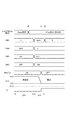
図1は、ホスト(DFP:Downstream Facing Port)のレセプタクル、デバイス(UFP:Upstream Facing Port)のレセプタクル、およびケーブルを模式的に示す図である。 FIG. 1 schematically shows a host (DFP: Downstream Facing Port) receptacle, a device (UFP: Upstream Facing Port) receptacle, and a cable.
リバーシブルケーブル300は、プラグ302、304と、ケーブル306を有する。プラグ302、304は同一形状を有し、それぞれに複数の端子(ピン)が設けられる。ケーブル306は、その内部の配線によりプラグ302、304それぞれの対応する複数のピン同士を結線する。
The
いま、プラグ302のあるピンP1に着目する。プラグ302が挿入されるホスト100側のレセプタクル102は、プラグ302が表向きで挿入されたときにピンP1と接触するピンCC1(Configuration Channel)を有する。また、レセプタクル102は、プラグ302をフリップして裏向きで挿入されたときにピンP1と接触するピンCC2を有する。なお、ここでの表、裏は便宜的なものであり、それぞれを第1の向き、第2の向きと読み替えてよい。
Now, focus on the pin P1 with the
プラグ304のピンP3は、配線308を介してピンP1と電気的に接続されている。プラグ304が挿入されるデバイス200側のレセプタクル202は、プラグ304が表向きで挿入されたときにピンP3と接触するピンCC1を有する。また、レセプタクル202は、プラグ304をフリップして裏向きで挿入されたときにピンP3と接触するピンCC2を有する。
The pin P3 of the
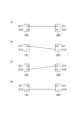
図2(a)〜(d)は、ホストのレセプタクル102とデバイスのレセプタクル202の接続パターンを示す図である。図2(a)は、プラグ302、プラグ304が両方表向きで挿入された状態、図2(b)は、プラグ302が表向き、プラグ304が裏向きで挿入された状態、図2(c)は、プラグ302が裏向き、プラグ304が表向きで挿入された状態、図2(d)は、プラグ302、304が両方裏向きで挿入された状態である。
FIGS. 2A to 2D are diagrams showing a connection pattern between the
リバーシブルケーブル300に対応するためには、図2(a)〜(d)の4状態のいずれであるかを判定する必要がある。
In order to cope with the
ここで、USB規格では、デュアルロールデバイス(DRD)と呼ばれるデバイスが存在する。デュアルロールデバイスは、接続相手のタイプ(役割)に応じて、ホストとデバイスが切り替え可能なものをいう。 Here, in the USB standard, there is a device called a dual roll device (DRD). The dual-role device is a device that can be switched between the host and the device according to the type (role) of the connection partner.
本発明は係る状況においてなされたものであり、そのある態様の例示的な目的のひとつは、デュアルロールデバイスにおいてリバーシブルケーブルに対応し、接続相手のタイプを検出可能な検出回路の提供にある。 The present invention has been made in such a situation, and one of exemplary purposes of an embodiment thereof is to provide a detection circuit that can detect a type of a connection partner corresponding to a reversible cable in a dual roll device.
本発明のある態様は、リバーシブルケーブルを介して接続される接続相手のタイプを検出する検出回路に関する。リバーシブルケーブルが係合するレセプタクルは、リバーシブルケーブルが表向き挿入された状態でリバーシブルケーブルのプラグのひとつのピンと接触する位置に配置された第1ピンと、リバーシブルケーブルが裏向きで挿入された状態でプラグのひとつのピンと接触する位置に配置された第2ピンと、を有している。検出回路は、検出ノードと、オン、オフ状態が切りかえ可能に構成され、オン状態において検出ノードとハイレベル電圧が供給される第1ラインの間に挿入される第1抵抗または第1電流源を含む第1検出部と、オン、オフ状態が切りかえ可能に構成され、オン状態において、検出ノードとローレベル電圧が供給される第2ラインの間に挿入される第2抵抗または第2電流源を含む第2検出部と、第1ピンを検出ノードに接続する第1接続状態と、第2ピンを検出ノードに接続する第2接続状態と、が切りかえ可能なセレクタと、第1検出部、第2検出部、セレクタを制御するとともに、検出ノードの電位にもとづいて接続相手のタイプを検出する判定器と、を備える。 One embodiment of the present invention relates to a detection circuit that detects a type of a connection partner connected via a reversible cable. The receptacle with which the reversible cable is engaged has a first pin arranged at a position in contact with one pin of the plug of the reversible cable with the reversible cable inserted face up, and the plug with the reversible cable inserted face down. And a second pin disposed at a position in contact with one pin. The detection circuit is configured to be able to switch between a detection node and an on / off state, and includes a first resistor or a first current source inserted between the detection node and a first line to which a high level voltage is supplied in the on state. A first detection unit including a second resistor or a second current source inserted between a detection node and a second line to which a low level voltage is supplied in the on state. A selector capable of switching between a second detection unit including a first connection state in which the first pin is connected to the detection node, and a second connection state in which the second pin is connected to the detection node; a first detection unit; And a determination unit that controls the detection unit and the selector and detects the type of the connection partner based on the potential of the detection node.
この態様によれば、リバーシブルケーブルに対応し、ケーブルの挿入の向き(Orientation)、接続相手の有無およびそのタイプを好適に検出できる。 According to this aspect, it corresponds to the reversible cable, and the insertion direction (Orientation) of the cable, the presence / absence of the connection partner, and the type thereof can be suitably detected.
コントローラは、第1検出部をオフ状態、第2検出部をオン状態、セレクタを第2接続状態とする第1状態φAと、第1検出部をオフ状態、第2検出部をオン状態、セレクタを第1接続状態とする第2状態φBと、第1検出部をオン状態、第2検出部をオフ状態、セレクタを第2接続状態とする第3状態φCと、第1検出部をオン状態、第2検出部をオフ状態、セレクタを第1接続状態とする第4状態φDと、所定の順序でを時分割にて切り替えてもよい。 The controller has a first state φA in which the first detection unit is in the off state, the second detection unit is in the on state, and the selector is in the second connection state, the first detection unit is in the off state, and the second detection unit is in the on state. Is the second state φB in which the first detector is in the first connection state, the first detector is in the on state, the second detector is in the off state, the third state φC in which the selector is in the second connection state, and the first detector is in the on state. The second detection unit may be switched off and the fourth state φD in which the selector is in the first connection state may be switched in a time-sharing manner in a predetermined order.
判定器は、検出ノードの電圧変化を検出すると、検出信号をアサートする電圧変化検出回路をさらに含んでもよい。コントローラは、検出信号が第1状態から第4状態のいずれにおいてアサートされたかにもとづいて、接続相手のタイプおよびリバーシブルケーブルの向きを判定してもよい。 The determiner may further include a voltage change detection circuit that asserts a detection signal when detecting a voltage change of the detection node. The controller may determine the type of the connection partner and the direction of the reversible cable based on whether the detection signal is asserted in the first state to the fourth state.
第1検出部は、検出ノードと第1ラインの間に直列に設けられた第1スイッチおよび第1抵抗を含み、第1スイッチのオン、オフ状態が、第1検出部のオン、オフ状態と対応してもよい。
接続相手がプルダウン状態である場合に、検出ノードには、第1抵抗と接続相手のプルダウン素子との分圧で得られる所定の電圧が発生する。したがって接続相手が、プルダウン状態に対応するタイプであることを検出できる。
The first detection unit includes a first switch and a first resistor provided in series between the detection node and the first line, and the on / off state of the first switch is the on / off state of the first detection unit. May correspond.
When the connection partner is in a pull-down state, a predetermined voltage obtained by dividing the first resistor and the pull-down element of the connection partner is generated at the detection node. Therefore, it can be detected that the connection partner is of a type corresponding to the pull-down state.
第1検出部は、検出ノードと第1ラインの間に直列に設けられた電流源を含み、電流源のオン、オフ状態が、第1検出部のオン、オフ状態と対応してもよい。
接続相手がプルダウン状態である場合に、検出ノードには、接続相手のプルダウン素子の電圧降下に応じた所定の電圧が発生する。したがって接続相手が、プルダウン状態に対応するタイプであることを検出できる。
The first detection unit may include a current source provided in series between the detection node and the first line, and the on / off state of the current source may correspond to the on / off state of the first detection unit.
When the connection partner is in the pull-down state, a predetermined voltage corresponding to the voltage drop of the pull-down element of the connection partner is generated at the detection node. Therefore, it can be detected that the connection partner is of a type corresponding to the pull-down state.
第2検出部は、検出ノードと第2ラインの間に直列に設けられた第2スイッチおよび第2抵抗を含み、第2スイッチのオン、オフ状態が、第2検出部のオン、オフ状態と対応してもよい。
接続相手がプルアップ素子を含む場合に、検出ノードには、第2抵抗と接続相手のプルアップ素子との分圧で得られる所定の電圧が発生する。したがって接続相手が、プルアップ状態に対応するタイプであることを検出できる。
The second detection unit includes a second switch and a second resistor provided in series between the detection node and the second line, and the on / off state of the second switch is the on / off state of the second detection unit. May correspond.
When the connection partner includes a pull-up element, a predetermined voltage obtained by voltage division between the second resistor and the pull-up element of the connection partner is generated at the detection node. Therefore, it can be detected that the connection partner is of a type corresponding to the pull-up state.
ある態様の検出回路は、データ通信を行うトランシーバをさらに備えてもよい。セレクタは、トランシーバを第1ピンに接続する状態と、トランシーバを第2ピンに接続する状態と、が切りかえ可能に構成されてもよい。 The detection circuit of an aspect may further include a transceiver that performs data communication. The selector may be configured to be switchable between a state in which the transceiver is connected to the first pin and a state in which the transceiver is connected to the second pin.
トランシーバは、検出ノードと接続されてもよい。 The transceiver may be connected to a detection node.
コントローラは、(i)第1ピンの接続先がプルアップ状態またはプルダウン状態であると判定したとき、セレクタに、トランシーバと第1ピンを接続せしめ、(ii)第2ピンの接続先がプルアップ状態またはプルダウン状態であると判定したとき、セレクタに、トランシーバと第2ピンを接続せしめてもよい。 When the controller determines that (i) the connection destination of the first pin is in the pull-up state or the pull-down state, the controller connects the transceiver and the first pin to the selector, and (ii) the connection destination of the second pin is the pull-up state. When it is determined that the state is the pull-down state, the transceiver and the second pin may be connected to the selector.
ある態様の検出回路は、所定電圧を生成する電圧源をさらに備えてもよい。セレクタは、電圧源を第1ピンに接続する状態と、電圧源を第2ピンに接続する状態と、が切りかえ可能に構成されてもよい。 The detection circuit according to an aspect may further include a voltage source that generates a predetermined voltage. The selector may be configured to be able to switch between a state in which the voltage source is connected to the first pin and a state in which the voltage source is connected to the second pin.
コントローラは、(i)第1ピンの接続先がオープン状態であると判定したとき、セレクタに、電圧源と第1ピンとを接続せしめ、(ii)第2ピンの接続先がオープン状態である判定されたとき、セレクタに、電圧源と第2ピンとを接続せしめてもよい。 When the controller determines that (i) the connection destination of the first pin is open, the controller connects the voltage source to the first pin, and (ii) determines that the connection destination of the second pin is open. When this is done, the voltage source and the second pin may be connected to the selector.
本発明の別の態様もまた、リバーシブルケーブルを介して接続される接続相手のタイプを検出する検出回路に関する。リバーシブルケーブルが係合するレセプタクルは、リバーシブルケーブルが表向き挿入された状態でリバーシブルケーブルのプラグのひとつのピンと接触する位置に配置された第1ピンと、リバーシブルケーブルが裏向きで挿入された状態でプラグのひとつのピンと接触する位置に配置された第2ピンと、を有する。検出回路は、検出ノードと、ハイレベル電圧が供給される第1ラインと検出ノードの間に直列に設けられた第1抵抗および第1スイッチと、ローレベル電圧が供給される第2ラインと検出ノードの間に直列に設けられた第2スイッチおよび第2抵抗と、第1ピンに検出ノードを接続する状態と、第2ピンに検出ノードを接続する状態と、が切りかえ可能に構成されたセレクタと、第1スイッチ、第2スイッチ、セレクタを制御するとともに検出ノードの電位にもとづき接続相手のタイプを判定する判定器と、を備える。 Another aspect of the present invention also relates to a detection circuit that detects a type of a connection partner connected via a reversible cable. The receptacle with which the reversible cable is engaged has a first pin arranged at a position in contact with one pin of the plug of the reversible cable with the reversible cable inserted face up, and the plug with the reversible cable inserted face down. And a second pin disposed at a position in contact with one pin. The detection circuit includes a detection node, a first resistor and a first switch provided in series between the detection line and a first line to which a high level voltage is supplied, and a second line to which a low level voltage is supplied. A selector configured to be able to switch between a second switch and a second resistor provided in series between the nodes, a state where the detection node is connected to the first pin, and a state where the detection node is connected to the second pin And a determiner that controls the first switch, the second switch, and the selector and determines the type of the connection partner based on the potential of the detection node.
判定器は、第1スイッチ、第2スイッチ、セレクタを制御するコントローラと、検出ノードの電圧変化を検出すると、検出信号をアサートする電圧変化検出回路と、を含んでもよい。判定器は、第1スイッチ、第2スイッチ、セレクタそれぞれの状態および検出信号の状態の組み合わせにもとづいて、接続相手のタイプおよびリバーシブルケーブルの向きを判定してもよい。 The determiner may include a controller that controls the first switch, the second switch, and the selector, and a voltage change detection circuit that asserts a detection signal when a voltage change of the detection node is detected. The determiner may determine the type of the connection partner and the direction of the reversible cable based on the combination of the state of each of the first switch, the second switch, and the selector and the state of the detection signal.
セレクタは、第1ピンと検出ノードの間が導通する状態と、第1ピンと検出ノードの間が遮断される状態とが切りかえ可能な第3スイッチと、第2ピンと検出ノードの間が導通する状態と、第2ピンと検出ノードの間が遮断される状態とが切りかえ可能な第4スイッチと、を含んでもよい。 The selector includes a third switch capable of switching between a state in which the first pin and the detection node are conductive and a state in which the first pin and the detection node are blocked, and a state in which the second pin and the detection node are conductive. And a fourth switch that can switch between a state in which the second pin and the detection node are blocked.
ある態様の検出回路は、検出ノードと接続されるトランシーバをさらに備えてもよい。 The detection circuit of an aspect may further include a transceiver connected to the detection node.
所定電圧を生成する電圧源をさらに備えてもよい。セレクタは、電圧源を第1ピンに接続する状態と、電圧源を第2ピンに接続する状態と、が切りかえ可能に構成されてもよい。 You may further provide the voltage source which produces | generates a predetermined voltage. The selector may be configured to be able to switch between a state in which the voltage source is connected to the first pin and a state in which the voltage source is connected to the second pin.
セレクタは、第1ピンと検出ノードの間が導通する状態と、第1ピンと電圧源の間が導通する状態と、第1ピンがハイインピーダンスとなる状態と、が切りかえ可能な第3スイッチと、第2ピンと検出ノードの間が導通する状態と、第2ピンと電圧源の間が導通する状態と、第2ピンがハイインピーダンスとなる状態と、が切りかえ可能な第4スイッチと、を含んでもよい。 The selector includes a third switch capable of switching between a state in which the first pin and the detection node are in conduction, a state in which the first pin and the voltage source are in conduction, and a state in which the first pin is in a high impedance state, A fourth switch that can switch between a state in which the second pin and the detection node are conducted, a state in which the second pin and the voltage source are conducted, and a state in which the second pin is in a high impedance state may be included.
ある態様の検出回路は、ひとつの半導体基板に集積化されてもよい。 An embodiment of the detection circuit may be integrated on one semiconductor substrate.
検出回路は、USB(Universal Serial Bus)規格に準拠してもよい。 The detection circuit may conform to the USB (Universal Serial Bus) standard.
本発明の別の態様は、ホスト・デバイスのデュアルロールデバイスに関する。デュアルロールデバイスは、レセプタクルと、レセプタクルと接続される上述のいずれかの態様の検出回路と、を備える。 Another aspect of the invention relates to a dual role device of a host device. The dual roll device includes a receptacle and the detection circuit according to any one of the above-described aspects connected to the receptacle.
なお、以上の構成要素の任意の組み合わせや本発明の構成要素や表現を、方法、装置、システムなどの間で相互に置換したものもまた、本発明の態様として有効である。 Note that any combination of the above-described constituent elements and the constituent elements and expressions of the present invention replaced with each other among methods, apparatuses, systems, and the like are also effective as an aspect of the present invention.
本発明のある態様によれば、リバーシブルケーブルに対応し、接続相手を好適に検出できる。 According to an aspect of the present invention, a connection partner can be suitably detected in correspondence with a reversible cable.
以下、本発明を好適な実施の形態をもとに図面を参照しながら説明する。各図面に示される同一または同等の構成要素、部材、処理には、同一の符号を付するものとし、適宜重複した説明は省略する。また、実施の形態は、発明を限定するものではなく例示であって、実施の形態に記述されるすべての特徴やその組み合わせは、必ずしも発明の本質的なものであるとは限らない。 The present invention will be described below based on preferred embodiments with reference to the drawings. The same or equivalent components, members, and processes shown in the drawings are denoted by the same reference numerals, and repeated descriptions are omitted as appropriate. The embodiments do not limit the invention but are exemplifications, and all features and combinations thereof described in the embodiments are not necessarily essential to the invention.
本明細書において、「部材Aが、部材Bと接続された状態」とは、部材Aと部材Bが物理的に直接的に接続される場合や、部材Aと部材Bが、それらの電気的な接続状態に実質的な影響を及ぼさない、あるいはそれらの結合により奏される機能や効果を損なわせない、その他の部材を介して間接的に接続される場合も含む。
同様に、「部材Cが、部材Aと部材Bの間に設けられた状態」とは、部材Aと部材C、あるいは部材Bと部材Cが直接的に接続される場合のほか、それらの電気的な接続状態に実質的な影響を及ぼさない、あるいはそれらの結合により奏される機能や効果を損なわせない、その他の部材を介して間接的に接続される場合も含む。
In this specification, “the state in which the member A is connected to the member B” means that the member A and the member B are physically directly connected, or the member A and the member B are electrically connected to each other. Including the case of being indirectly connected through other members that do not substantially affect the state of connection, or do not impair the functions and effects achieved by the combination thereof.
Similarly, “the state in which the member C is provided between the member A and the member B” refers to the case where the member A and the member C or the member B and the member C are directly connected, as well as their electric It includes cases where the connection is indirectly made through other members that do not substantially affect the general connection state, or that do not impair the functions and effects achieved by their combination.
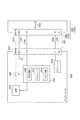
図3は、実施の形態に係る検出回路400を備える電子機器(デュアルロールデバイス)500の回路図である。デュアルロールデバイス500は、ケーブル300を介して、デバイス200もしくはホスト100のいずれかと接続可能である。デュアルロールデバイス500は、接続相手がデバイス200であるときには、ホストとして動作し、接続相手がホスト100であるときにはデバイスとして動作するデュアルロールデバイスである。
FIG. 3 is a circuit diagram of an electronic apparatus (dual roll device) 500 including the
デュアルロールデバイス500は、将来策定されるUSB(Universal Serial Bus)規格に準拠してもよい。ケーブル300は、複数の配線を含む。バスライン310、接地ライン312は、ホストからデバイスへとバス電圧VBUSおよび接地電圧VGNDを供給するために設けられる。データライン(D+,D−)314、316は、デュアルロールデバイス500と接続相手(100,200)の間でシリアルデータ通信を行うために利用される。CC(Configuration Channel)ライン318は、デュアルロールデバイス500と接続相手(100,200)の間で、接続相手の接続の有無、そのタイプ(デバイスかホストか)を判定するために利用され、さらにはサポートするプロファイルやID(識別番号)などに関するデータを送受信するために利用される。CCライン318は、図1の配線308に相当する。
The dual-
デュアルロールデバイス500は、レセプタクル502、電源504、出力スイッチ506、トランシーバ508、バスコントローラ510を備える。
The
レセプタクル502には、ケーブル300を介して接続相手(100,200)が接続される。ケーブル300は、図1に示すようにリバーシブルとなっており、レセプタクル502は、レセプタクル102や202と同様に、回転対称のピン配置を有する。図3では、端子VBUS,GND,COM,D+,D−それぞれが1個のみ示されるが、実際にはペアで設けられ、各ペアは回転対称に配置される。たとえばCCピンは、CC1ピンとCC2ピンを含む。
A connection partner (100, 200) is connected to the
トランシーバ508は、データライン314、316を介して、接続相手のトランシーバと接続され、双方向でシリアルデータ通信を行う。
The
電源504は、デュアルロールデバイス500がホストとして動作するときにアクティブとなり、バス電圧VBUSを生成し、バスライン310を介して接続相手であるデバイス200に供給する。出力スイッチ506は、バス電圧VBUSの供給、遮断を切りかえるためにバスライン310の経路上に設けられる。
The
バスコントローラ510は、デュアルロールデバイス500のバスに関するコントローラである。バスコントローラ510は、たとえば検出回路400、トランシーバ512、ロジック部514を備える。検出回路400およびトランシーバ512は、CCライン318と接続される。検出回路400は、CCライン318の電気的状態、言い換えればそれが接続されるCCピンの電気的状態にもとづいて、接続相手(100,200)の有無およびそのタイプ(デバイスかホストか)を判定する。加えて、後述のように、ケーブル300はリバーシブルケーブルであるから、検出回路400は、その挿入方向も検出する。
The
トランシーバ512は、CCライン318を介して接続相手(100,200)と通信を行い、相互にサポートするプロファイルやID(識別番号)などを送受信し、ネゴシエーションを行う。
The
そのほかバスコントローラ510には、過電圧検出回路や過電流検出回路が含まれるが、図3では省略される。ロジック部514は、検出回路400による判定結果、トランシーバ512によるネゴシエーションの結果にもとづいて、デュアルロールデバイス500の電源504、出力スイッチ506、トランシーバ508等を制御する。具体的には、ロジック部514は、電源504のイネーブル、ディセーブルの切りかえ、バス電圧VBUSの設定、出力スイッチ506のオン、オフ制御などを行う。
In addition, the
以上がデュアルロールデバイス500の概要である。続いて接続相手のホスト100およびデバイス200について説明する。図4(a)、(b)は、接続相手であるホスト100およびデバイス200を示す図である。図4(a)を参照し、ホスト100を説明する。レセプタクル102は、CCライン318と接続されうる回転対称に配置された一対のCC1ピン、CC2ピンを有する。ホスト100において、第1ピンCC1、第2ピンCC2は、プルアップ素子を介してプルアップされる。プルアップ素子は、プルアップ抵抗Rpであってもよい。
The outline of the
図4(b)を参照し、デバイス200を説明する。レセプタクル202もレセプタクル102と同様に、CCライン318と接続されうる回転対称に配置された一対のピンCC1、CC2を有する。デバイス200において、第1ピンCC1、第2ピンCC2は、プルダウン素子を介してプルダウンされる。
The
なお、USBでは、プルアップ状態がホスト、プルダウン状態がデバイスに対応するが、別の規格においてそれらの関係は逆であってもよい。 In USB, the pull-up state corresponds to the host, and the pull-down state corresponds to the device. However, in another standard, the relationship may be reversed.
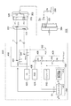
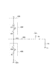
続いて、図4(a)、(b)のホスト100、デバイス200を検出可能な検出回路400について説明する。図5は、実施の形態に係る検出回路400の回路図である。検出回路400は、レセプタクル502に接続されたリバーシブルケーブル300の向きおよび接続相手のタイプを検出する。図5には、レセプタクル502にプラグ302が裏向きで挿入される状態が示される。
Next, the
検出回路400は、ひとつの半導体基板上に集積化された機能IC(Integrated Circuit)である。第1端子T1、第2端子T2はそれぞれ、レセプタクル502のCC1、CC2ピンと接続される。
The
レセプタクル502の第1ピンCC1は、リバーシブルケーブル300が表向き挿入された状態(不図示)でリバーシブルケーブル300のプラグ302のひとつのピンP1(CCピンとも称される)であってCCライン318と接続されるピンと接触する位置に配置される。
The first pin CC1 of the
第2ピンCC2は、リバーシブルケーブル300が裏向きで挿入された状態(図5)でプラグ302のピンP1と接触する位置に配置される。第1ピンCC1と第2ピンCC2は、回転対称の位置に配置される。
The second pin CC2 is disposed at a position where it comes into contact with the pin P1 of the
検出回路400は、主として、検出ノード402、判定器404、第1検出部406、第2検出部408、セレクタ410を備える。
The
第1検出部406は、オン、オフ状態が切りかえ可能に構成される。第1検出部406は、オン状態において検出ノード402とハイレベル電圧VHが供給される第1ライン426の間に挿入される第1抵抗R1を含む。電圧源424は、ハイレベル電圧VHを生成する。
The
たとえば第1検出部406は、検出ノード402と第1ライン426の間に直列に設けられた第1スイッチSW1および第1抵抗R1を含む。第1スイッチSW1のオン、オフ状態が、第1検出部406のオン、オフ状態と対応する。第1スイッチSW1と第1抵抗R1は入れかえてもよい。
For example, the
検出ノード402の接続先にプルダウン素子Rdが設けられ、接続相手がプルダウン状態である場合、第1検出部406がオンすると、検出ノード402には、第1ライン426のハイレベル電圧VHと接続相手の接地電圧VSSを、R1とRdで分圧した電圧が発生する。R1>Rdとした場合、検出ノード402の電圧VCCは、しきい値電圧VTH(たとえば中点電圧VH/2)より低くなる。
When the pull-down element Rd is provided at the connection destination of the
反対に、検出ノード402の接続先がプルダウン状態ではないとき、具体的には接続相手がプルアップ素子(すなわちプルアップ抵抗Rpもしくはプルアップ用の電流源CSp)を含むとき、もしくは接続相手が抜去された状態では、検出ノード402の電圧VCCは、しきい値電圧VTHより高くなる。
Conversely, when the connection destination of the
第2検出部408は、オン、オフ状態が切りかえ可能に構成される。第2検出部408は、オン状態において、検出ノード402とローレベル電圧VLが供給される第2ライン428の間に挿入される第2抵抗R2を含む。
The
たとえば第2検出部408は、検出ノード402と第2ライン428の間に直列に設けられた第2スイッチSW2および第2抵抗R2を含む。第2スイッチSW2のオン、オフ状態が、第2検出部408のオン、オフ状態と対応する。第2スイッチSW2と第2抵抗R2は入れかえてもよい。
For example, the
検出ノード402の接続先にプルアップ素子Rpもしくは電流源CSpが設けられ、接続相手がプルアップ状態である場合に、第2検出部408がオンすると、検出ノード402には、接続相手のハイレベル電圧VDDと、第2ライン428のローレベル電圧VLを、抵抗RpとR2で分圧した電圧が発生する。Rp>R2とした場合、検出ノード402の電圧VCCは、しきい値電圧VTH(たとえば中点電圧VH/2)より低くなる。
When the pull-up element Rp or current source CSp is provided at the connection destination of the
反対に、検出ノード402の接続先がプルアップ状態でないとき、具体的には接続相手がプルダウン素子(すなわちプルダウン抵抗Rd)を含むとき、もしくは接続相手が抜去された状態では、検出ノード402の電圧VCCは、しきい値電圧VTHより高くなる。
On the other hand, when the connection destination of the
セレクタ410は、第1ピンCC1を検出ノード402に接続する第1接続状態φ1と、第2ピンCC2を検出ノード402に接続する第2接続状態φ2と、が切りかえ可能に構成される。
The
判定器404は、第1検出部406、第2検出部408、セレクタ410を制御するとともに、検出ノード402の電位VCCにもとづいて、接続相手のタイプを検出する。
The
判定器404は、コントローラ412および電圧変化検出回路414を含む。コントローラ412は、制御信号S2を生成し、第1検出部406、第2検出部408、セレクタ410を制御する。電圧変化検出回路414は、検出ノード402の電圧変化を検出すると、検出信号S1をアサート(たとえはハイレベル)する。電圧変化検出回路414は、検出ノード402の電位VCCを、所定の少なくともひとつのしきい値電圧VTHと比較するコンパレータで構成することができる。コンパレータは、電位VCCが単一のしきい値電圧より高いか低いかを判定する電圧コンパレータであってもよいし、電位VCCが所定の電圧範囲に含まれるか否かを判定するウインドウコンパレータであってもよい。
The
判定器404は、第1検出部406、第2検出部408、セレクタ410それぞれの状態と、検出信号S1の状態の組み合わせにもとづいて、接続相手のタイプを検出する。
The
ケーブル300の向きおよび接続相手のタイプの組み合わせは、以下の通りである。
The combinations of the direction of the
(1)ケーブルが表向き、接続相手がホスト
(2)ケーブルが裏向き、接続相手がホスト
(3)ケーブルが表向き、接続相手がデバイス
(4)ケーブルが裏向き、接続相手がデバイス
(5)接続相手が抜去
(1) Cable is face up, connection partner is host (2) Cable is face down, connection partner is host (3) Cable is face up, connection partner is device (4) Cable is face down, connection partner is device (5) Connection The opponent is removed
コントローラ412は、以下の4つの状態を時分割で切り替える。なお状態遷移の順序は特に限定されない。
第1状態φA: セレクタ410を第2接続状態φ2、第1検出部406をオフ状態、第2検出部408をオン状態
第2状態φB: セレクタ410を第1接続状態φ1、第1検出部406をオフ状態、第2検出部408をオン状態
第3状態φC: セレクタ410を第2接続状態φ2、第1検出部406をオン状態、第2検出部408をオフ状態
第4状態φD: セレクタ410を第1接続状態φ1、第1検出部406をオン状態、第2検出部408をオフ状態
The
First state φA: The
コントローラ412は、検出信号S1が第1状態φAから第4状態φDのいずれにおいてアサートされたかにもとづいて、接続相手のタイプおよびリバーシブルケーブルの向きを判定する。
The
具体的には、第1状態φAにおいて検出信号S1がアサートされたとき、ケーブル300は裏向き、接続相手はホストである。第2状態φBにおいて検出信号S1がアサートされたとき、ケーブル300は表向き、接続相手はホストである。第3状態φCにおいて検出信号S1がアサートされたとき、ケーブル300は裏向き、接続相手はデバイスである。第4状態φDにおいて検出信号S1がアサートされたとき、ケーブル300は表向き、接続相手はデバイスである。
Specifically, when the detection signal S1 is asserted in the first state φA, the
図3に示したように、デュアルロールデバイス500は、検出回路400に加えてトランシーバ512を備える。トランシーバ512は、検出回路400と同一の半導体チップに集積化されてもよい。
As shown in FIG. 3, the dual-
セレクタ410は、検出回路400による判定の完了後、判定結果に応じて、トランシーバ512を第1ピンCC1に接続する状態と、トランシーバ512を第2ピンCC2に接続する状態と、が切りかえ可能に構成される。
The
具体的にはトランシーバ512は、検出ノード402と接続される。
コントローラ412は、(i)第1ピンCC1の接続先がプルアップまたはプルダウンされていると判定されたとき、セレクタ410にトランシーバ512を第1ピンCC1と接続させる。反対に(ii)第2ピンCC2の接続先がプルアップまたはプルダウンされていると判定されたとき、セレクタ410にトランシーバ512を第2ピンCC2と接続させる。
Specifically, the
The controller 412 (i) causes the
プラグ302は、CCライン318と接続されるピンP1と回転対称な位置に配置されたピンP2を備える。プラグ302は、ピンP2を介して電源電圧VDDを受けて動作可能なICチップ320を内蔵してもよい。この場合、検出回路400は、所定電圧VDDを生成する電圧源422を備えてもよい。そしてセレクタ410は、電圧源422を第1ピンCC1に接続する状態と、電圧源422を第2ピンCC2に接続する状態と、が切りかえ可能に構成される。
The
コントローラ412は、(i)第1ピンCC1の接続先がオープン状態である判定されたとき、セレクタ410に電圧源を第1ピンCC1と接続させる。反対にコントローラ412は、(ii)第2ピンCC2の接続先がオープン状態である判定されたとき、セレクタ410に電圧源422を第2ピンCC2と接続させる。
The controller 412 (i) causes the
たとえばセレクタ410は、第3スイッチSW3、第4スイッチSW4を含む。第3スイッチSW3は、第1ピンCC1と検出ノード402の間が導通する状態aと、第1ピンCC1と電圧源422の間が導通する状態bと、第1ピンCC1がハイインピーダンスとなる状態openと、が切りかえ可能となっている。第4スイッチSW4は、第2ピンCC2と検出ノード402の間が導通する状態aと、第2ピンCC2と電圧源422の間が導通する状態bと、第2ピンCC2がハイインピーダンスとなる状態openと、が切りかえ可能となっている。
For example, the
つまり、第3スイッチSW3が状態aであり、第4スイッチSW4がopen状態のとき、セレクタ410は第1接続状態φ1である。第3スイッチSW3がopen状態であり、第4スイッチSW4が状態aのとき、セレクタ410は第2接続状態φ2である。
That is, when the third switch SW3 is in the state a and the fourth switch SW4 is in the open state, the
以上が検出回路400の構成である。続いてその動作を、いくつかの場合に分けて説明する。
The above is the configuration of the
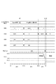
(1)ケーブルが表向き、接続相手がデバイス
図6は、図5の検出回路400の第1の動作波形図である。この例では接続相手としてプルダウン抵抗Rdを備えるデバイス200が接続され、ケーブル300が表向きであり、デバイス200のプルダウン抵抗Rdが、レセプタクル502のCC1ピン側に接続されるものとする。
(1) Cable is face up, connection partner is device FIG. 6 is a first operation waveform diagram of the
接続相手を検出してその種類を特定する前の段階で、ロールトグル信号RoleTglがアサート(ON)されており、検出回路400は、上述した4つの状態φA,φB,φC,φDを時分割で順に繰り返す。時刻t0より前の初期状態では、レセプタクル502にはプラグ302は挿入されておらず、オープン状態である。
The roll toggle signal RoleTgl is asserted (ON) before the connection partner is detected and its type is specified, and the
時刻t0に、レセプタクル502にプラグ302が挿入され、接続相手のデバイス200が接続される。
At time t0, the
プラグ302の挿入後、状態φA〜φCの区間は、検出ノード402の電圧VCCは、ハイレベル電圧VH=5Vである。状態φDに切りかわると、CC1ピン側に接続されたデバイス200側のプルダウン抵抗Rdと、第1検出部406の第1抵抗R1が接続され、検出ノード402の電圧VCCがある電圧レベル(たとえば1.8V)まで低下する。この電圧レベルは、第1抵抗R1とプルダウン抵抗Rdの分圧比で定まる。
After the
時刻t1に、検出ノード402の電圧VCCが1.8Vまで低下すると検出信号S1がアサートされる。コントローラ412は、これを契機としてロールトグル信号RoleTglをネゲート(OFF)とともに、時刻t2以降、第1スイッチSW1〜第4スイッチSW4のスイッチングを停止し、それぞれを適切な状態で固定する。
When the voltage VCC at the
この例では、CC1ピンにデバイス200のプルダウン抵抗Rdが接続されているから、デュアルロールデバイス500をホストとして動作させるように、スイッチSW1〜SW4が制御される。具体的には、CC1ピンがプルアップされるようにSW1がオン、第2検出部408がオフするようにSW2がオフされる。またCC1ピンをトランシーバ512と接続するために第3スイッチSW3が状態aとなり、CC2ピンに電源電圧VDDを供給すべく第4スイッチSW4が状態bとなる。
In this example, since the pull-down resistor Rd of the
(2)ケーブルが裏向き、接続相手がデバイス
図7は、図5の検出回路400の第2の動作波形図である。この例では接続相手としてプルダウン抵抗Rdを備えるデバイス200が接続され、ケーブル300が裏向きであり、デバイス200のプルダウン抵抗Rdが、レセプタクル502のCC2ピン側に接続されるものとする。
(2) Cable is face down, connection partner is device FIG. 7 is a second operation waveform diagram of the
時刻t0に、レセプタクル502にプラグ302が挿入され、接続相手のデバイス200が接続される。プラグ302の挿入後、状態φA〜φBの区間は、検出ノード402の電圧VCCは、ハイレベル電圧VH=5Vである。状態φCに切りかわると、CC2ピン側に接続されたデバイス200側のプルダウン抵抗Rdと、第1検出部406の第1抵抗R1が接続され、検出ノード402の電圧VCCがある電圧レベル(たとえば1.8V)まで低下する。
At time t0, the
時刻t1に、検出ノード402の電圧VCCが1.8Vまで低下すると検出信号S1がアサートされる。コントローラ412は、これを契機としてロールトグル信号RoleTglをネゲート(OFF)とともに、時刻t2以降、第1スイッチSW1〜第4スイッチSW4のスイッチングを停止し、それぞれを適切な状態で固定する。
When the voltage VCC at the
この例では、CC2ピンにデバイス200のプルダウン抵抗Rdが接続されているから、デュアルロールデバイス500をホストとして動作させるように、スイッチSW1〜SW4が制御される。具体的には、CC2ピンがプルアップされるようにSW1がオン、第2検出部408がオフするようにSW2がオフされる。またCC2ピンをトランシーバ512と接続するために第4スイッチSW4が状態aとなり、CC1ピンに電源電圧VDDを供給すべく第3スイッチSW3が状態bとなる。
In this example, since the pull-down resistor Rd of the
(3)ケーブルが表向き、接続相手がホスト
図8は、図5の検出回路400の第3の動作波形図である。この例では接続相手としてプルアップ抵抗Rpを備えるホスト100が接続され、ケーブル300が表向きであり、ホスト100のプルアップ抵抗Rpが、レセプタクル502のCC1ピン側に接続されるものとする。
(3) Cable is face up, connection partner is host FIG. 8 is a third operation waveform diagram of the
時刻t0に、レセプタクル502にプラグ302が挿入され、接続相手のホスト100が接続される。プラグ302の挿入後、状態φAの区間は、検出ノード402の電圧VCCは、ハイレベル電圧VH=5Vである。状態φBに切りかわると、CC1ピン側に接続されたホスト100側のプルアップ抵抗Rpと、第2検出部408の第2抵抗R2が接続され、検出ノード402の電圧VCCがある電圧レベル(たとえば1.8V)まで低下する。
At time t0, the
時刻t1に、検出ノード402の電圧VCCが1.8Vまで低下すると検出信号S1がアサートされる。コントローラ412は、これを契機としてロールトグル信号RoleTglをネゲート(OFF)とともに、時刻t2以降、第1スイッチSW1〜第4スイッチSW4のスイッチングを停止し、それぞれを適切な状態で固定する。
When the voltage VCC at the
この例では、CC1ピンにホスト100のプルアップ抵抗Rpが接続されているから、デュアルロールデバイス500をデバイスとして動作させるように、スイッチSW1〜SW4が制御される。具体的には、CC1ピンがプルダウンされるようにSW2がオン、第1検出部406がオフするようにSW1がオフされる。また第3スイッチSW3が状態a、第4スイッチSW4が状態bとされる。
In this example, since the pull-up resistor Rp of the
(4)ケーブルが裏向き、接続相手がホスト
図9は、図5の検出回路400の第4の動作波形図である。この例では接続相手としてプルアップ抵抗Rpを備えるホスト100が接続され、ケーブル300が裏向きであり、ホスト100のプルアップ抵抗Rpが、レセプタクル502のCC2ピン側に接続されるものとする。
(4) Cable is face down, connection partner is host FIG. 9 is a fourth operation waveform diagram of the
時刻t0に、レセプタクル502にプラグ302が挿入され、接続相手のホスト100が接続される。プラグ302の挿入後、状態φAに切りかわると、CC2ピン側に接続されたホスト100側のプルアップ抵抗Rpと、第2検出部408の第2抵抗R2が接続され、検出ノード402の電圧VCCがある電圧レベル(たとえば1.8V)まで低下する。
At time t0, the
時刻t1に、検出ノード402の電圧VCCが1.8Vまで低下すると検出信号S1がアサートされる。コントローラ412は、これを契機としてロールトグル信号RoleTglをネゲート(OFF)とともに、時刻t2以降、第1スイッチSW1〜第4スイッチSW4のスイッチングを停止し、それぞれを適切な状態で固定する。
When the voltage VCC at the
この例では、CC2ピンにホスト100のプルアップ抵抗Rpが接続されているから、デュアルロールデバイス500をデバイスとして動作させるように、スイッチSW1〜SW4が制御される。具体的には、CC2ピンがプルダウンされるようにSW2がオン、第1検出部406がオフするようにSW1がオフされる。また第3スイッチSW3が状態b、第4スイッチSW4が状態aとされる。
In this example, since the pull-up resistor Rp of the
以上が検出回路400の動作である。
このように、検出回路400によれば、リバーシブルケーブルに対応して、接続相手を好適に検出することができる。
また図5の検出回路400は、想定されるケーブルの状態(表裏)と、接続相手の種類(ホスト、デバイス)の組み合わせを、時分割で判定することとした。これにより、CC1ピンとCC2ピンの状態を個別のハードウェア(回路)を用いて判定する場合に比べて、ハードウェア資源を大幅に削減できる。
The above is the operation of the
As described above, according to the
Further, the
以上、本発明について、実施の形態をもとに説明した。この実施の形態は例示であり、それらの各構成要素や各処理プロセスの組み合わせにいろいろな変形例が可能なこと、またそうした変形例も本発明の範囲にあることは当業者に理解されるところである。以下、こうした変形例について説明する。 The present invention has been described based on the embodiments. This embodiment is an exemplification, and it will be understood by those skilled in the art that various modifications can be made to combinations of the respective constituent elements and processing processes, and such modifications are within the scope of the present invention. is there. Hereinafter, such modifications will be described.
(第1変形例)
実施の形態では、第1検出部406を第1抵抗R1で、第2検出部408を第2抵抗R2で構成した場合を説明したが本発明はそれには限定されない。図10は、第1変形例に係る第1検出部406の回路図である。
第1検出部406は、第1抵抗R1に代えて、第1電流源CS1を含む。第1電流源CS1のオン、オフが切りかえ可能な場合、第1スイッチSW1は省略可能である。
(First modification)
In the embodiment, the case where the
The
図10の第1検出部406と、接続相手であるデバイス200のプルダウン素子Rdが接続されると、検出ノード402に、所定の電圧VCC=Ic×Rdを発生させることができる。電流Icを適切に設定することで、抵抗RdとR1の分圧で得られる電圧と同電位を、検出ノード402に発生させることができる。
When the
(第2変形例)
ホスト100は、図4(a)のプルアップ抵抗Rpに代えて、定電流Icを生成する電流源CSpを含んでもよい。この場合、ホスト100の電流源CSpと、デュアルロールデバイス500の第2検出部408の第2抵抗R2が接続されると、検出ノード402に、所定の電圧VCC=Ic×R2を発生させることができる。電流Icを適切に設定することで、抵抗R2とRpの分圧で得られる電圧と同電位を、検出ノード402に発生させることができる。
(Second modification)
The
(第3変形例)
実施の形態では、USB規格に沿って発明を説明したが、その用途はUSBには限定されず、検出回路400は、リバーシブルケーブルに対応するさまざまなバス規格に適用することができる。
(Third Modification)
Although the invention has been described in accordance with the USB standard in the embodiment, the application is not limited to the USB, and the
(第4変形例)
デバイス200は、プルダウン抵抗Rdに代えて、定電流Icを生成する電流源を備えてもよい。この場合、第1検出部406の第1抵抗R1とデバイス200の電流源が接続されると、検出ノード402の電位VCCは、VCC=VH−R1×Icとなる。
同様に、デュアルロールデバイス500の第2検出部408は、第2抵抗R2に代えて、定電流Icを生成する第2電流源を備えてもよい。この場合、第2検出部408の第2電流源とホスト100のプルアップ抵抗Rpが接続されると、検出ノード402の電位VCCは、VCC=VH−Rp×Icとなる。
(Fourth modification)
The
Similarly, the
(用途)
最後に電子機器600の具体例を説明する。図11は、電子機器600の斜視図である。電子機器600は、たとえばテレビや液晶ディスプレイ、ノート型コンピュータなどである。
(Use)
Finally, a specific example of the
電子機器600は、筐体602、ディスプレイパネル604および上述のデュアルロールデバイス500を備える。デュアルロールデバイス500の電源504はAC/DCコンバータであり、AC電圧VACをDC電圧VBUSに変換する。実施の形態に係る検出回路400は、バスコントローラ510に含まれる。DC電圧VBUSの設定電圧VSETは、バスコントローラ510により選択される。レセプタクル502は、筐体820の前面あるいは背面に設置され、リバーシブルケーブル300が挿入可能となっている。
The
なお電子機器600は、携帯電話端末、タブレット端末、デジタルカメラ、デジタルビデオカメラなどであってもよい。
The
実施の形態にもとづき、具体的な用語を用いて本発明を説明したが、実施の形態は、本発明の原理、応用を示しているにすぎず、実施の形態には、請求の範囲に規定された本発明の思想を逸脱しない範囲において、多くの変形例や配置の変更が認められる。 Although the present invention has been described using specific terms based on the embodiments, the embodiments only illustrate the principles and applications of the present invention, and the embodiments are defined in the claims. Many variations and modifications of the arrangement are permitted without departing from the spirit of the present invention.
100…ホスト、102…レセプタクル、200…デバイス、202…レセプタクル、300…ケーブル、302,304…プラグ、306…ケーブル、308…配線、310…バスライン、312…接地ライン、314,316…データライン、318…CCライン、320…ICチップ、400…検出回路、T1…第1端子、T2…第2端子、SW1…第1スイッチ、SW2…第2スイッチ、SW3…第3スイッチ、SW4…第4スイッチ、Rp…第1抵抗、Rd…第2抵抗、402…検出ノード、404…判定器、406…第1検出部、408…第2検出部、410…セレクタ、412…コントローラ、414…電圧変化検出回路、422…電圧源、426…ライン、500…デュアルロールデバイス、502…レセプタクル、504…電源、506…出力スイッチ、508…トランシーバ、510…バスコントローラ、512…トランシーバ、514…ロジック部、600…電子機器、602…筐体、604…ディスプレイパネル。
DESCRIPTION OF
Claims (21)
前記リバーシブルケーブルが係合するレセプタクルは、
前記リバーシブルケーブルが表向き挿入された状態で前記リバーシブルケーブルのプラグのひとつのピンと接触する位置に配置された第1ピンと、
前記リバーシブルケーブルが裏向きで挿入された状態で前記プラグの前記ひとつのピンと接触する位置に配置された第2ピンと、
を有しており、
前記検出回路は、
検出ノードと、
オン、オフ状態が切りかえ可能に構成され、オン状態において前記検出ノードとハイレベル電圧が供給される第1ラインの間に挿入される第1抵抗または第1電流源を含む第1検出部と、
オン、オフ状態が切りかえ可能に構成され、オン状態において、前記検出ノードとローレベル電圧が供給される第2ラインの間に挿入される第2抵抗または第2電流源を含む第2検出部と、
前記第1ピンを前記検出ノードに接続する第1接続状態と、前記第2ピンを前記検出ノードに接続する第2接続状態と、が切りかえ可能なセレクタと、
前記第1検出部、前記第2検出部、前記セレクタを制御するとともに、前記検出ノードの電位にもとづいて、前記接続相手のタイプを検出する判定器と、
を備えることを特徴とする検出回路。 A detection circuit for detecting a type of a connection partner connected via a reversible cable,
The receptacle with which the reversible cable is engaged is
A first pin disposed at a position in contact with one pin of the plug of the reversible cable in a state where the reversible cable is inserted face up;
A second pin disposed at a position in contact with the one pin of the plug in a state where the reversible cable is inserted face down;
Have
The detection circuit includes:
A discovery node;
A first detector including a first resistor or a first current source configured to be switched between an on state and an off state, and inserted between the detection node and a first line to which a high level voltage is supplied in the on state;
A second detector including a second resistor or a second current source inserted between the detection node and a second line to which a low-level voltage is supplied; ,
A selector capable of switching between a first connection state in which the first pin is connected to the detection node and a second connection state in which the second pin is connected to the detection node;
A determination unit that controls the first detection unit, the second detection unit, and the selector, and that detects a type of the connection partner based on a potential of the detection node;
A detection circuit comprising:
前記コントローラは、
前記第1検出部をオフ状態、前記第2検出部をオン状態、前記セレクタを前記第2接続状態とする第1状態と、
前記第1検出部をオフ状態、前記第2検出部をオン状態、前記セレクタを前記第1接続状態とする第2状態と、
前記第1検出部をオン状態、前記第2検出部をオフ状態、前記セレクタを前記第2接続状態とする第3状態と、
前記第1検出部をオン状態、前記第2検出部をオフ状態、前記セレクタを前記第1接続状態とする第4状態と、
を、所定の順序で時分割にて切り替えることを特徴とする請求項1に記載の検出回路。 The determination unit includes a controller that controls the first detection unit, the second detection unit, and the selector,
The controller is
A first state in which the first detector is in an off state, the second detector is in an on state, and the selector is in the second connection state;
A second state in which the first detection unit is in an off state, the second detection unit is in an on state, and the selector is in the first connection state;
A third state in which the first detector is in an on state, the second detector is in an off state, and the selector is in the second connection state;
A fourth state in which the first detection unit is in an on state, the second detection unit is in an off state, and the selector is in the first connection state;
The detection circuit according to claim 1, wherein the switching is switched in a time-sharing manner in a predetermined order.
前記コントローラは、前記検出信号が前記第1状態から前記第4状態のいずれにおいてアサートされたかにもとづいて、前記接続相手のタイプおよび前記リバーシブルケーブルの向きを判定することを特徴とする請求項2に記載の検出回路。 The determination unit further includes a voltage change detection circuit that asserts a detection signal when detecting a voltage change of the detection node;
3. The controller according to claim 2, wherein the controller determines the type of the connection partner and the direction of the reversible cable based on whether the detection signal is asserted in the first state to the fourth state. The detection circuit described.
前記セレクタは、前記トランシーバを前記第1ピンに接続する状態と、前記トランシーバを前記第2ピンに接続する状態と、が切りかえ可能に構成されることを特徴とする請求項1から6のいずれかに記載の検出回路。 Further comprising a transceiver for data communication,
7. The selector according to claim 1, wherein the selector is configured to be switchable between a state in which the transceiver is connected to the first pin and a state in which the transceiver is connected to the second pin. The detection circuit described in 1.
(i)前記第1ピンの接続先がプルアップ状態またはプルダウン状態であると判定したとき、前記セレクタに、前記トランシーバと前記第1ピンを接続せしめ、
(ii)前記第2ピンの接続先がプルアップ状態またはプルダウン状態であると判定したとき、前記セレクタに、前記トランシーバと前記第2ピンを接続せしめることを特徴とする請求項7または8に記載の検出回路。 The determiner is
(I) When it is determined that the connection destination of the first pin is in a pull-up state or a pull-down state, the transceiver and the first pin are connected to the selector;
(Ii) When it is determined that the connection destination of the second pin is in a pull-up state or a pull-down state, the transceiver and the second pin are connected to the selector. Detection circuit.
前記セレクタは、前記電圧源を前記第1ピンに接続する状態と、前記電圧源を前記第2ピンに接続する状態と、が切りかえ可能に構成されることを特徴とする請求項1から9のいずれかに記載の検出回路。 A voltage source for generating a predetermined voltage;
10. The selector according to claim 1, wherein the selector is configured to be switchable between a state in which the voltage source is connected to the first pin and a state in which the voltage source is connected to the second pin. The detection circuit according to any one of the above.
(i)前記第1ピンの接続先がオープン状態であると判定したとき、前記セレクタに、前記電圧源と前記第1ピンとを接続せしめ、
(ii)前記第2ピンの接続先がオープン状態である判定されたとき、前記セレクタに、前記電圧源と前記第2ピンとを接続せしめることを特徴とする請求項10に記載の検出回路。 The determiner is
(I) When it is determined that the connection destination of the first pin is in an open state, the voltage source and the first pin are connected to the selector;
(Ii) The detection circuit according to claim 10, wherein when the connection destination of the second pin is determined to be in an open state, the voltage source and the second pin are connected to the selector.
前記リバーシブルケーブルが係合するレセプタクルは、
前記リバーシブルケーブルが表向き挿入された状態で前記リバーシブルケーブルのプラグのひとつのピンと接触する位置に配置された第1ピンと、
前記リバーシブルケーブルが裏向きで挿入された状態で前記プラグの前記ひとつのピンと接触する位置に配置された第2ピンと、
を有しており、
前記検出回路は、
検出ノードと、
ハイレベル電圧が供給される第1ラインと前記検出ノードの間に直列に設けられた第1抵抗および第1スイッチと、
ローレベル電圧が供給される第2ラインと前記検出ノードの間に直列に設けられた第2スイッチおよび第2抵抗と、
前記第1ピンに前記検出ノードを接続する状態と、前記第2ピンに前記検出ノードを接続する状態と、が切りかえ可能に構成されたセレクタと、
前記第1スイッチ、前記第2スイッチ、前記セレクタを制御するとともに、前記検出ノードの電位にもとづき前記接続相手のタイプを判定する判定器と、
を備えることを特徴とする検出回路。 A detection circuit for detecting a type of a connection partner connected via a reversible cable,
The receptacle with which the reversible cable is engaged is
A first pin disposed at a position in contact with one pin of the plug of the reversible cable in a state where the reversible cable is inserted face up;
A second pin disposed at a position in contact with the one pin of the plug in a state where the reversible cable is inserted face down;
Have
The detection circuit includes:
A discovery node;
A first resistor and a first switch provided in series between a first line to which a high level voltage is supplied and the detection node;
A second switch and a second resistor provided in series between a second line to which a low level voltage is supplied and the detection node;
A selector configured to be switchable between a state in which the detection node is connected to the first pin and a state in which the detection node is connected to the second pin;
A determinator for controlling the first switch, the second switch, and the selector, and determining the type of the connection partner based on the potential of the detection node;
A detection circuit comprising:
前記第1スイッチ、前記第2スイッチ、前記セレクタを制御するコントローラと、
前記検出ノードの電圧変化を検出すると、検出信号をアサートする電圧変化検出回路と、
を含み、
前記第1スイッチ、前記第2スイッチ、前記セレクタそれぞれの状態および前記検出信号の状態の組み合わせにもとづいて、前記接続相手のタイプおよび前記リバーシブルケーブルの向きを判定する請求項12に記載の検出回路。 The determiner is
A controller for controlling the first switch, the second switch, and the selector;
A voltage change detection circuit that asserts a detection signal when detecting a voltage change of the detection node;
Including
The detection circuit according to claim 12, wherein the type of the connection partner and the direction of the reversible cable are determined based on a combination of a state of each of the first switch, the second switch, and the selector and a state of the detection signal.
前記第1ピンと前記検出ノードの間が導通する状態と、前記第1ピンと前記検出ノードの間が遮断される状態とが切りかえ可能な第3スイッチと、
前記第2ピンと前記検出ノードの間が導通する状態と、前記第2ピンと前記検出ノードの間が遮断される状態とが切りかえ可能な第4スイッチと、
を含むことを特徴とする請求項12または13に記載の検出回路。 The selector is
A third switch capable of switching between a state in which the first pin and the detection node are electrically connected and a state in which the first pin and the detection node are blocked;
A fourth switch capable of switching between a state in which the second pin and the detection node are conductive and a state in which the second pin and the detection node are blocked;
The detection circuit according to claim 12 or 13, characterized by comprising:
前記セレクタは、前記電圧源を前記第1ピンに接続する状態と、前記電圧源を前記第2ピンに接続する状態と、が切りかえ可能に構成されることを特徴とする請求項12または13に記載の検出回路。 A voltage source for generating a predetermined voltage;
14. The selector according to claim 12, wherein the selector is configured to be switchable between a state in which the voltage source is connected to the first pin and a state in which the voltage source is connected to the second pin. The detection circuit described.
前記第1ピンと前記検出ノードの間が導通する状態と、前記第1ピンと前記電圧源の間が導通する状態と、前記第1ピンがハイインピーダンスとなる状態と、が切りかえ可能な第3スイッチと、
前記第2ピンと前記検出ノードの間が導通する状態と、前記第2ピンと前記電圧源の間が導通する状態と、前記第2ピンがハイインピーダンスとなる状態と、が切りかえ可能な第4スイッチと、
を含むことを特徴とする請求項16に記載の検出回路。 The selector is
A third switch capable of switching between a state in which the first pin and the detection node are in conduction, a state in which the first pin and the voltage source are in conduction, and a state in which the first pin is in a high impedance state; ,
A fourth switch capable of switching between a state in which the second pin and the detection node are electrically connected, a state in which the second pin and the voltage source are electrically connected, and a state in which the second pin is in a high impedance state; ,
The detection circuit according to claim 16, comprising:
前記レセプタクルと接続される請求項1から19のいずれかに記載の検出回路と、
を備えることを特徴とするホスト・デバイスのデュアルロールデバイス。 A receptacle,
The detection circuit according to any one of claims 1 to 19, which is connected to the receptacle;
A dual-role device of a host device, comprising:
前記リバーシブルケーブルが係合するレセプタクルは、
前記リバーシブルケーブルが表向き挿入された状態で前記リバーシブルケーブルのプラグのひとつのピンと接触する位置に配置された第1ピンと、
前記リバーシブルケーブルが裏向きで挿入された状態で前記プラグの前記ひとつのピンと接触する位置に配置された第2ピンと、
を有しており、
前記方法は、所定の順序で時分割にて実行される、
前記第1ピンを検出ノードに接続し、かつ前記検出ノードとハイレベル電圧が供給される第1ラインの間に第1抵抗または第1電流源を挿入し、前記検出ノードの電位を判定する第1ステップと、
前記第1ピンを検出ノードに接続し、かつ前記検出ノードとローレベル電圧が供給される第2ラインの間に第2抵抗または第2電流源を挿入し、前記検出ノードの電位を判定する第2ステップと、
前記第2ピンを検出ノードに接続し、かつ前記検出ノードと前記第1ラインの間に前記第1抵抗または前記第1電流源を挿入し、前記検出ノードの電位を判定する第3ステップと、
前記第2ピンを検出ノードに接続し、かつ前記検出ノードと前記第2ラインの間に前記第2抵抗または前記第2電流源を挿入し、前記検出ノードの電位を判定する第4ステップと、
を備えることを特徴とする方法。 A method for detecting a type of a connection partner connected via a reversible cable,
The receptacle with which the reversible cable is engaged is
A first pin disposed at a position in contact with one pin of the plug of the reversible cable in a state where the reversible cable is inserted face up;
A second pin disposed at a position in contact with the one pin of the plug in a state where the reversible cable is inserted face down;
Have
The method is performed in a time-sharing manner in a predetermined order,
The first pin is connected to a detection node, and a first resistor or a first current source is inserted between the detection node and a first line to which a high level voltage is supplied, and a potential of the detection node is determined. One step,
A first resistor is connected to the detection node, and a second resistor or a second current source is inserted between the detection node and a second line to which a low level voltage is supplied, and a potential of the detection node is determined. Two steps,
A third step of connecting the second pin to a detection node and inserting the first resistor or the first current source between the detection node and the first line to determine a potential of the detection node;
A fourth step of connecting the second pin to a detection node, inserting the second resistor or the second current source between the detection node and the second line, and determining a potential of the detection node;
A method comprising the steps of:
Priority Applications (1)
| Application Number | Priority Date | Filing Date | Title |
|---|---|---|---|
| JP2015155386A JP2017033461A (en) | 2015-08-05 | 2015-08-05 | Detection circuit and detection method for reversible cable, and dual roll device of host device using the same |
Applications Claiming Priority (1)
| Application Number | Priority Date | Filing Date | Title |
|---|---|---|---|
| JP2015155386A JP2017033461A (en) | 2015-08-05 | 2015-08-05 | Detection circuit and detection method for reversible cable, and dual roll device of host device using the same |
Publications (1)
| Publication Number | Publication Date |
|---|---|
| JP2017033461A true JP2017033461A (en) | 2017-02-09 |
Family
ID=57986369
Family Applications (1)
| Application Number | Title | Priority Date | Filing Date |
|---|---|---|---|
| JP2015155386A Pending JP2017033461A (en) | 2015-08-05 | 2015-08-05 | Detection circuit and detection method for reversible cable, and dual roll device of host device using the same |
Country Status (1)
| Country | Link |
|---|---|
| JP (1) | JP2017033461A (en) |
Cited By (6)
| Publication number | Priority date | Publication date | Assignee | Title |
|---|---|---|---|---|
| JP2018173886A (en) * | 2017-03-31 | 2018-11-08 | キヤノン株式会社 | Electronic apparatus and control method therefor |
| JP2018180793A (en) * | 2017-04-07 | 2018-11-15 | キヤノン株式会社 | Electronic apparatus and control method thereof |
| CN108984454A (en) * | 2018-09-13 | 2018-12-11 | 武汉芯昌科技有限公司 | A kind of slave role integrated interface circuit and detection method based on TYPE-C agreement |
| CN109462104A (en) * | 2018-11-23 | 2019-03-12 | 上海机器人产业技术研究院有限公司 | A kind of OTG line of Type-C interface |
| CN110098826A (en) * | 2019-04-19 | 2019-08-06 | 深圳市泰信通信息技术有限公司 | The detection method of chip circuit and its state of a control, electronic equipment and medium |
| JP2021184218A (en) * | 2020-05-22 | 2021-12-02 | ルネサスエレクトロニクス株式会社 | Connection detection circuit and semiconductor device |
-
2015
- 2015-08-05 JP JP2015155386A patent/JP2017033461A/en active Pending
Cited By (7)
| Publication number | Priority date | Publication date | Assignee | Title |
|---|---|---|---|---|
| JP2018173886A (en) * | 2017-03-31 | 2018-11-08 | キヤノン株式会社 | Electronic apparatus and control method therefor |
| JP2018180793A (en) * | 2017-04-07 | 2018-11-15 | キヤノン株式会社 | Electronic apparatus and control method thereof |
| CN108984454A (en) * | 2018-09-13 | 2018-12-11 | 武汉芯昌科技有限公司 | A kind of slave role integrated interface circuit and detection method based on TYPE-C agreement |
| CN108984454B (en) * | 2018-09-13 | 2024-03-22 | 武汉芯昌科技有限公司 | Master-slave role integrated interface circuit based on TYPE-C protocol and detection method |
| CN109462104A (en) * | 2018-11-23 | 2019-03-12 | 上海机器人产业技术研究院有限公司 | A kind of OTG line of Type-C interface |
| CN110098826A (en) * | 2019-04-19 | 2019-08-06 | 深圳市泰信通信息技术有限公司 | The detection method of chip circuit and its state of a control, electronic equipment and medium |
| JP2021184218A (en) * | 2020-05-22 | 2021-12-02 | ルネサスエレクトロニクス株式会社 | Connection detection circuit and semiconductor device |
Similar Documents
| Publication | Publication Date | Title |
|---|---|---|
| JP2017033461A (en) | Detection circuit and detection method for reversible cable, and dual roll device of host device using the same | |
| CN109490684B (en) | Apparatus and method for detecting leakage current generation condition in USB interface | |
| US8683090B2 (en) | Methods, systems and apparatus for determining whether an accessory includes particular circuitry | |
| US10324507B2 (en) | Methods, systems and apparatus for enabling an accessory for use with a host device | |
| US9356460B2 (en) | Method and apparatus of fast battery charging with universal high power input source | |
| US8880909B2 (en) | Auto-detect polling for correct handshake to USB client | |
| JP6505283B2 (en) | Power-up control circuit and mobile battery | |
| CN106354591B (en) | Detection circuit of universal serial bus | |
| US20130207595A1 (en) | USB Dedicated Charger Identification Circuit | |
| US20090027010A1 (en) | Portable communication device and method for charging through discernment of charging cable | |
| US10845398B2 (en) | Interface circuitry for bidirectional power connector | |
| TWI764195B (en) | Usb interface detection module | |
| TW201334412A (en) | Determining circuit | |
| TWI501484B (en) | Techniques for detecting removal of a connector | |
| JP2020008898A (en) | Electronic equipment | |
| JP6661342B2 (en) | Port connection circuit, port connection control method, electronic equipment | |
| CN109062846B (en) | Universal serial bus device and operation method thereof | |
| TWI554889B (en) | Electric system | |
| CN107480084A (en) | Type C mobile terminals charge and data transmission method, device and storage medium | |
| US10193286B2 (en) | Electronic device and control method thereof | |
| US20160365805A1 (en) | Power transfer systems | |
| TWI666875B (en) | Connection circuit and connection method thereof | |
| TWI806769B (en) | Power delivery device and control method of power supply path | |
| CN108631377B (en) | Power-on control circuit and mobile power supply device using same | |
| CN110597375B (en) | External equipment power supply device |