JP2017019413A - Temperature-increasing system - Google Patents

Temperature-increasing system Download PDF

Info

Publication number
JP2017019413A
JP2017019413A JP2015139034A JP2015139034A JP2017019413A JP 2017019413 A JP2017019413 A JP 2017019413A JP 2015139034 A JP2015139034 A JP 2015139034A JP 2015139034 A JP2015139034 A JP 2015139034A JP 2017019413 A JP2017019413 A JP 2017019413A
Authority
JP
Japan
Prior art keywords
temperature
refrigerant
fan
engine
exhaust
Prior art date
Legal status (The legal status is an assumption and is not a legal conclusion. Google has not performed a legal analysis and makes no representation as to the accuracy of the status listed.)
Pending
Application number
JP2015139034A
Other languages
Japanese (ja)
Inventor
清貴 石川
Seiki Ishikawa
清貴 石川
直 片山
Sunao Katayama
直 片山
直紀 谷口
Naoki Taniguchi
直紀 谷口
Current Assignee (The listed assignees may be inaccurate. Google has not performed a legal analysis and makes no representation or warranty as to the accuracy of the list.)
Mitsubishi Motors Corp
Original Assignee
Mitsubishi Motors Corp
Priority date (The priority date is an assumption and is not a legal conclusion. Google has not performed a legal analysis and makes no representation as to the accuracy of the date listed.)
Filing date
Publication date
Application filed by Mitsubishi Motors Corp filed Critical Mitsubishi Motors Corp
Priority to JP2015139034A priority Critical patent/JP2017019413A/en
Publication of JP2017019413A publication Critical patent/JP2017019413A/en
Pending legal-status Critical Current

Links

Images

Classifications

    • YGENERAL TAGGING OF NEW TECHNOLOGICAL DEVELOPMENTS; GENERAL TAGGING OF CROSS-SECTIONAL TECHNOLOGIES SPANNING OVER SEVERAL SECTIONS OF THE IPC; TECHNICAL SUBJECTS COVERED BY FORMER USPC CROSS-REFERENCE ART COLLECTIONS [XRACs] AND DIGESTS
    • Y02TECHNOLOGIES OR APPLICATIONS FOR MITIGATION OR ADAPTATION AGAINST CLIMATE CHANGE
    • Y02TCLIMATE CHANGE MITIGATION TECHNOLOGIES RELATED TO TRANSPORTATION
    • Y02T10/00Road transport of goods or passengers
    • Y02T10/60Other road transportation technologies with climate change mitigation effect
    • Y02T10/7072Electromobility specific charging systems or methods for batteries, ultracapacitors, supercapacitors or double-layer capacitors

Abstract

PROBLEM TO BE SOLVED: To provide a temperature-increasing system for a hybrid vehicle, with power equipment protected by quickly securing the flow rate of a coolant for cooling the power equipment that includes a motor.SOLUTION: A temperature-increasing system, disposed in a hybrid vehicle 1 that is incorporated with an engine 2 and a motor, for warming a coolant used for cooling power equipment 3 including a motor, further includes: a cooling circuit 30 provided with a pump 31 for pressure-transmitting the coolant and a radiator 33 for cooling the coolant; an electric fan 4, disposed between the radiator 33 and an exhaust system 2A of the engine 2, for air-blowing in a direction toward the radiator 33 from the exhaust system 2A; and a resistor 6 disposed in series with the fan 4 on a first electric circuit 10 on which the fan 4 and an on-vehicle battery 5 are disposed. Further, the resistor 6 is disposed at an immediate downstream part 30a of the pump 31 and in contact with the cooling circuit 30.SELECTED DRAWING: Figure 1

Description

本発明は、ハイブリッド車両の駆動用モータ等の電力機器を冷却する冷媒を温める昇温システムに関する。   The present invention relates to a temperature raising system that warms a refrigerant that cools a power device such as a drive motor of a hybrid vehicle.

従来、車両に搭載されたエンジンやモータ等を冷却する手法として、ポンプとラジエータとが介装された冷却回路に冷媒を循環させるものが知られている。すなわち、ポンプで圧送された冷媒が、エンジンやモータ等の発熱装置を冷却したのち、ラジエータで冷却されて再びポンプに戻るものである。所定流量の冷媒が冷却回路内を流通することで、エンジンやモータ等の適切な冷却が可能となる。   2. Description of the Related Art Conventionally, as a method for cooling an engine, a motor, and the like mounted on a vehicle, a method of circulating a refrigerant through a cooling circuit in which a pump and a radiator are interposed is known. That is, the refrigerant pumped by the pump cools a heat generating device such as an engine or a motor, then cools by a radiator and returns to the pump again. By allowing the refrigerant having a predetermined flow rate to flow through the cooling circuit, it is possible to appropriately cool the engine, the motor, and the like.

ところで、冷媒が凍結するような極寒の環境では、冷媒の粘度が高くなって冷却回路内を流れ難くなり、冷却回路における冷媒の流量が不足することがある。冷媒の流量不足はエンジンやモータ等の冷却不足を招くことから、このような環境下ではこれらの装置が故障するおそれがある。そこで、冷媒の低温化が懸念される場合には、冷媒を昇温してその流量を確保することが求められる。   By the way, in an extremely cold environment where the refrigerant freezes, the viscosity of the refrigerant becomes so high that it becomes difficult to flow through the cooling circuit, and the flow rate of the refrigerant in the cooling circuit may be insufficient. Insufficient refrigerant flow leads to insufficient cooling of the engine, motor, etc., and there is a risk that these devices will fail in such an environment. Therefore, when there is a concern about lowering the temperature of the refrigerant, it is required to raise the temperature of the refrigerant and ensure its flow rate.

これに関し、特許文献1には、エンジン冷却用冷却水(冷媒)が通過するラジエータを加温する技術が記載されている。この技術は、エンジンを搭載した車両において暖機時間の短縮及び極低温環境での暖房性能の向上等を実現するために、エンジンの排気系を通過して予熱された空気をラジエータへ送風するものである。このようにラジエータが温められれば、ラジエータを通過する冷媒も加温されうる。   In this regard, Patent Document 1 describes a technique for heating a radiator through which engine cooling water (refrigerant) passes. This technology blows preheated air to the radiator through the exhaust system of the engine in order to shorten the warm-up time and improve the heating performance in a cryogenic environment in a vehicle equipped with an engine. It is. If the radiator is heated in this way, the refrigerant passing through the radiator can also be heated.

特開2012−246790号公報JP 2012-246790 A

しかしながら、特許文献1の技術は、エンジンの排気系の熱を利用してラジエータを加温するものであるため、エンジンの排気系の温度がある程度高くならない限り冷媒を加温することができない。つまり、エンジンの排気熱を利用した昇温手法では、冷媒を速やかに温めることができない可能性がある。特にエンジンは、モータやインバータといった電力機器に比べて温度上昇に時間がかかるため、エンジンとモータとを搭載したハイブリッド車両において、モータ等の電力機器を冷却する冷媒をエンジンの排気熱で温めるようとすると、冷媒の流量が確保されるよりも前に電力機器が高温化する虞がある。したがって、特許文献1の技術をそのままハイブリッド車両に適用した場合には、冷却を必要とする電力機器を適切に保護できない可能性がある。   However, since the technology of Patent Document 1 uses the heat of the exhaust system of the engine to heat the radiator, the refrigerant cannot be heated unless the temperature of the exhaust system of the engine becomes high to some extent. That is, there is a possibility that the refrigerant cannot be quickly heated by the temperature raising method using the exhaust heat of the engine. In particular, the engine takes longer to rise in temperature than electric devices such as motors and inverters. Therefore, in a hybrid vehicle equipped with an engine and a motor, the refrigerant that cools the electric devices such as the motor is heated by the exhaust heat of the engine. Then, there is a possibility that the electric power device will be heated before the refrigerant flow rate is secured. Therefore, when the technique of Patent Document 1 is applied to a hybrid vehicle as it is, there is a possibility that power equipment that requires cooling cannot be properly protected.

また、冷媒はポンプによって圧送されることで冷却回路を循環するため、冷媒の流量を速やかに確保するには、ポンプの内部やポンプの近く(直下流,直上流)にある冷媒を温めることが有効である。しかしながら、特許文献1の技術はラジエータを加温するものであるため、ラジエータとポンプとが互いに近接して配置されない限り、ポンプの近くにある冷媒を効率よく温めることができない。したがって、特許文献1の技術では、冷媒の流量を速やかに確保することができない虞がある。この点においても、特許文献1の技術には改善の余地がある。   In addition, since the refrigerant circulates in the cooling circuit by being pumped by the pump, in order to quickly secure the flow rate of the refrigerant, it is necessary to warm the refrigerant in the pump or near the pump (directly downstream, immediately upstream). It is valid. However, since the technique of Patent Document 1 heats the radiator, the refrigerant in the vicinity of the pump cannot be efficiently heated unless the radiator and the pump are arranged close to each other. Therefore, with the technique of Patent Document 1, there is a possibility that the flow rate of the refrigerant cannot be secured quickly. In this respect as well, there is room for improvement in the technique of Patent Document 1.

本件は、このような課題に鑑み案出されたもので、ハイブリッド車両の昇温システムに関し、モータを含む電力機器を冷却する冷媒の流量を速やかに確保して電力機器を適切に保護することを目的の一つとする。なお、この目的に限らず、後述する発明を実施するための形態に示す各構成により導かれる作用効果であって、従来の技術によっては得られない作用効果を奏することも本件の他の目的として位置づけることができる。   The present case has been devised in view of such a problem, and relates to a temperature rising system for a hybrid vehicle, and promptly securing a flow rate of a refrigerant for cooling a power device including a motor to appropriately protect the power device. One of the purposes. The present invention is not limited to this purpose, and is a function and effect derived from each configuration shown in the embodiments for carrying out the invention described later, and other effects of the present invention are to obtain a function and effect that cannot be obtained by conventional techniques. Can be positioned.

(1)ここで開示する昇温システムは、エンジンとモータとを搭載したハイブリッド車両に設けられ、前記モータを含む電力機器を冷却する冷媒を温める昇温システムである。本昇温システムは、前記冷媒を圧送するポンプと前記冷媒を冷却するためのラジエータとを介装した冷却回路と、前記ラジエータと前記エンジンの排気系統との間に設置され、前記排気系統から前記ラジエータへ向かう方向に送風する電動のファンと、前記ファン及び車載の電池が配置された第一電気回路と、前記第一電気回路上において前記ファンと直列に配置され、前記冷却回路における前記ポンプの直下流部に接触配置された抵抗器と、を備える。   (1) A temperature raising system disclosed herein is a temperature raising system that is provided in a hybrid vehicle equipped with an engine and a motor and that heats a refrigerant that cools electric power equipment including the motor. The temperature raising system is installed between a cooling circuit including a pump for pumping the refrigerant and a radiator for cooling the refrigerant, and between the radiator and the exhaust system of the engine. An electric fan that blows air in a direction toward the radiator, a first electric circuit in which the fan and the on-vehicle battery are arranged, and the fan in the cooling circuit that is arranged in series with the fan on the first electric circuit. And a resistor disposed in contact with the immediately downstream portion.

(2)前記ラジエータが、前記冷却回路における前記ポンプよりも上流に配置されることが好ましい。
(3)前記昇温システムが、前記ファン及び前記電池が配置されるとともに前記抵抗器を迂回する第二電気回路と、前記第一電気回路及び前記第二電気回路の何れか一方に通電する切替部と、前記切替部を制御することで前記ファンの作動状態を制御する制御装置と、を備えることが好ましい。前記制御装置は、前記エンジンの排気温度が所定排気温未満である場合に、前記第一電気回路に通電して前記ファンを回転させ、前記排気温度が前記所定排気温以上である場合に、前記第二電気回路に通電して前記ファンを回転させることが好ましい。
(2) It is preferable that the radiator is disposed upstream of the pump in the cooling circuit.
(3) The temperature raising system includes a second electric circuit in which the fan and the battery are arranged and bypasses the resistor, and a switch for energizing either the first electric circuit or the second electric circuit And a control device that controls the operating state of the fan by controlling the switching unit. When the exhaust temperature of the engine is lower than a predetermined exhaust temperature, the control device rotates the fan by energizing the first electric circuit, and when the exhaust temperature is equal to or higher than the predetermined exhaust temperature, Preferably, the fan is rotated by energizing the second electric circuit.

(4)前記制御装置は、前記排気温度が高いほど前記ファンの回転速度を高めることが好ましい。
(5)前記制御装置は、前記ハイブリッド車両を走行可能状態に切り替える操作がされた時点で、前記冷媒の温度が所定値未満であれば前記第一電気回路に通電して前記ファンを回転させることが好ましい。
(6)前記制御装置は、前記ハイブリッド車両の走行モードが前記モータを駆動源とするEVモードに設定されている場合でも、前記時点で前記冷媒の温度が前記所定値未満であれば前記エンジンを強制的に始動させることが好ましい。
(4) It is preferable that the said control apparatus raises the rotational speed of the said fan, so that the said exhaust temperature is high.
(5) When the operation of switching the hybrid vehicle to a travelable state is performed, the control device energizes the first electric circuit to rotate the fan if the temperature of the refrigerant is less than a predetermined value. Is preferred.
(6) Even if the driving mode of the hybrid vehicle is set to an EV mode using the motor as a drive source, the control device may turn off the engine if the temperature of the refrigerant is lower than the predetermined value at the time point. It is preferable to force start.

開示の昇温システムによれば、抵抗器の熱とエンジンの排気系統の熱とを利用して冷媒を温められることから、冷媒の流量を速やかに確保することができる。これにより、冷却を必要とする電力機器(例えばモータ,インバータ,車載充電器等)を適切に保護することができる。   According to the temperature raising system of the disclosure, the refrigerant can be warmed using the heat of the resistor and the heat of the exhaust system of the engine, so that the flow rate of the refrigerant can be secured quickly. Thereby, the electric power apparatus (for example, a motor, an inverter, a vehicle-mounted charger etc.) which requires cooling can be protected appropriately.

一実施形態にかかる昇温システムの全体構成を例示する模式図である。It is a mimetic diagram illustrating the whole temperature rise system composition concerning one embodiment. 本昇温システムの制御手順を例示するフローチャートである。It is a flowchart which illustrates the control procedure of this temperature rising system.

図面を参照して、実施形態としての昇温システムについて説明する。以下に示す実施形態はあくまでも例示に過ぎず、以下の実施形態で明示しない種々の変形や技術の適用を排除する意図はない。本実施形態の各構成は、それらの趣旨を逸脱しない範囲で種々変形して実施することができるとともに、必要に応じて取捨選択することができ、あるいは適宜組み合わせることが可能である。   A temperature raising system as an embodiment will be described with reference to the drawings. The embodiment described below is merely an example, and there is no intention of excluding various modifications and technical applications that are not explicitly described in the following embodiment. Each configuration of the present embodiment can be implemented with various modifications without departing from the spirit of the present embodiment, and can be selected or combined as necessary.

[1.システム構成]
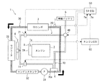
図1に、実施形態としての昇温システムの全体構成を例示する。この昇温システムは、エンジン2と駆動用のモータとを搭載したハイブリッド車両1(以下、車両1と略称する)に設けられる。車両1には、モータ,インバータ,DC-DCコンバータ,車載充電器等の電力機器が搭載される。これらの電力機器は作動時の発熱量が大きいことから冷却回路30を流れる冷媒により冷却される。以下、これらの電力機器を「EVコンポ3」という。なお、車両1には、この冷却回路30とは別に、エンジン2を冷却するための冷却回路(図示略)も設けられる。冷却回路30は、例えば配管やホースで形成される。
[1. System configuration]
In FIG. 1, the whole structure of the temperature rising system as embodiment is illustrated. This temperature raising system is provided in a hybrid vehicle 1 (hereinafter abbreviated as vehicle 1) equipped with an engine 2 and a driving motor. The vehicle 1 is equipped with power devices such as a motor, an inverter, a DC-DC converter, and an in-vehicle charger. Since these electric power devices generate a large amount of heat during operation, they are cooled by the refrigerant flowing through the cooling circuit 30. Hereinafter, these electric power devices are referred to as “EV component 3”. In addition to the cooling circuit 30, the vehicle 1 is also provided with a cooling circuit (not shown) for cooling the engine 2. The cooling circuit 30 is formed by piping or a hose, for example.

冷却回路30には、上述のEVコンポ3に加えて、ポンプ31,コンデンスタンク32及びラジエータ33が介装される。ポンプ31は、EVコンポ3を冷却する冷媒を冷却回路30内で循環させるための電動圧送器(電制ウォーターポンプ)であり、オン状態で(稼動時に)冷媒を圧送する。なお、冷媒の流通方向(循環方向)は、図1中に太矢印で示すように、反時計回りである。コンデンスタンク32は、ポンプ31へ気泡が流入することを防止するための気液分離タンクであり、ポンプ31の直上流に設けられて冷媒に含まれる気泡を液体成分から分離して外部に排出する。ラジエータ33は、冷媒を冷却するための熱交換器であり、コンデンスタンク32よりも上流に設けられる。つまり、ラジエータ33は、冷却回路30におけるポンプ31よりも上流に配置される。   In addition to the above-described EV component 3, the cooling circuit 30 is provided with a pump 31, a condensation tank 32, and a radiator 33. The pump 31 is an electric pressure feeder (electrically controlled water pump) for circulating the refrigerant for cooling the EV component 3 in the cooling circuit 30, and pumps the refrigerant in the on state (during operation). The refrigerant flow direction (circulation direction) is counterclockwise as shown by a thick arrow in FIG. The condensation tank 32 is a gas-liquid separation tank for preventing air bubbles from flowing into the pump 31, and is provided immediately upstream of the pump 31 to separate the air bubbles contained in the refrigerant from the liquid component and discharge the air to the outside. . The radiator 33 is a heat exchanger for cooling the refrigerant, and is provided upstream of the condensation tank 32. That is, the radiator 33 is disposed upstream of the pump 31 in the cooling circuit 30.

また、ラジエータ33は、エンジン2のエキゾーストマニホールド2A(排気系統,以下、エキマニ2Aと略称する)と並んで設けられる。エキマニ2Aは、エンジン2の作動時に排出される高温の燃焼ガス(排気)の流路を形成するものである。エキマニ2Aの温度や、エキマニ2Aの周辺部品や周囲の空気の温度は、エンジン2の排気の熱によって上昇する。   The radiator 33 is provided side by side with an exhaust manifold 2A (exhaust system, hereinafter abbreviated as an exhaust manifold 2A) of the engine 2. The exhaust manifold 2 </ b> A forms a flow path of high-temperature combustion gas (exhaust gas) discharged when the engine 2 is operated. The temperature of the exhaust manifold 2 </ b> A, the peripheral parts of the exhaust manifold 2 </ b> A, and the ambient air temperature rise due to the heat of exhaust from the engine 2.

ラジエータ33及びエキマニ2Aの間には、ラジエータ33に空気を流すためのファン4が設置される。つまり、ラジエータ33,ファン4,エキマニ2Aは、この順で一列に並べられる。ファン4は、車載の補機バッテリ5(電池)の電力で作動する電動ファンであり、複数の羽根が回転することで空気の流れを生成する。ファン4と補機バッテリ5とは、二つの電気回路10,20でそれぞれ接続される。言い換えると、二つの電気回路10,20の何れにも、ファン4及び補機バッテリ5が配置される。二つの電気回路10,20には、何れか一方の回路にだけ電流を流す切替回路40(切替部)が設けられる。また、二つの電気回路10,20の一方にはレジスタ6(抵抗器)が配され、通電される回路10,20によってファン4に印加される電圧値が異なるようになっている。以下、二つの電気回路10,20を区別する場合には、レジスタ6が配された一方を第一電気回路10といい、他方を第二電気回路20という。第二電気回路20は、レジスタ6を迂回する回路であるともいえる。   Between the radiator 33 and the exhaust manifold 2A, a fan 4 for allowing air to flow through the radiator 33 is installed. That is, the radiator 33, the fan 4, and the exhaust manifold 2A are arranged in a line in this order. The fan 4 is an electric fan that operates with the electric power of the in-vehicle auxiliary battery 5 (battery), and generates a flow of air by rotating a plurality of blades. The fan 4 and the auxiliary battery 5 are connected by two electric circuits 10 and 20, respectively. In other words, the fan 4 and the auxiliary battery 5 are disposed in any of the two electric circuits 10 and 20. The two electric circuits 10 and 20 are provided with a switching circuit 40 (switching unit) that allows a current to flow through only one of the circuits. In addition, a resistor 6 (resistor) is disposed in one of the two electric circuits 10 and 20 so that the voltage value applied to the fan 4 varies depending on the circuits 10 and 20 that are energized. Hereinafter, when the two electric circuits 10 and 20 are distinguished from each other, one of the registers 6 is referred to as a first electric circuit 10 and the other is referred to as a second electric circuit 20. It can be said that the second electric circuit 20 is a circuit that bypasses the register 6.

ファン4は、印加される電圧の大きさに応じて、その回転速度が二段階に(低速,高速に)切り替わる。電圧が低い場合にはファン4は低速で回転する。以下、ファン4のこの作動状態をロー駆動という。また、電圧が高い場合にはファン4は高速で回転する。以下、ファン4のこの作動状態をハイ駆動という。第一電気回路10は、レジスタ6の抵抗値の分だけ第二電気回路20よりも電圧が低くなることから、第一電気回路10に電流を流すとファン4がロー駆動となる。反対に、第二電気回路20に電流を流すとファン4がハイ駆動となる。言い換えると、第一電気回路10は、ファン4のロー駆動時に電流が流れる電気回路であり、第二電気回路20は、ファン4のハイ駆動時に電流が流れる電気回路である。   The rotation speed of the fan 4 is switched between two stages (low speed and high speed) according to the magnitude of the applied voltage. When the voltage is low, the fan 4 rotates at a low speed. Hereinafter, this operating state of the fan 4 is referred to as low drive. When the voltage is high, the fan 4 rotates at a high speed. Hereinafter, this operating state of the fan 4 is referred to as high drive. Since the voltage of the first electric circuit 10 is lower than that of the second electric circuit 20 by the resistance value of the resistor 6, the fan 4 is driven low when a current is passed through the first electric circuit 10. On the other hand, when a current is passed through the second electric circuit 20, the fan 4 is driven high. In other words, the first electric circuit 10 is an electric circuit through which a current flows when the fan 4 is driven low, and the second electric circuit 20 is an electric circuit through which a current flows when the fan 4 is driven high.

切替回路40は、補機バッテリ5とファン4との間の通電経路を第一電気回路10又は第二電気回路20に切り替えるものであり、例えばスイッチ,コンタクタ,リレー等で構成される。切替回路40は、二つの電気回路10,20の何れか一方に通電し、他方を遮断することで、ファン4の作動状態をロー駆動とハイ駆動とに切り替える。切替回路40は、後述のEV−ECU50によって制御される。   The switching circuit 40 switches the energization path between the auxiliary battery 5 and the fan 4 to the first electric circuit 10 or the second electric circuit 20, and is composed of, for example, a switch, a contactor, a relay, or the like. The switching circuit 40 energizes one of the two electric circuits 10 and 20 and shuts off the other, thereby switching the operating state of the fan 4 between low driving and high driving. The switching circuit 40 is controlled by an EV-ECU 50 described later.

レジスタ6は、ファン4と直列に接続され、第一電気回路10の電圧値を下げることでファン4の回転速度を下げて、ファン4の作動時に生じる音を低減するものである。レジスタ6は、冷却回路30におけるポンプ31の直下流部30aに接触配置される。これにより、レジスタ6と冷却回路30との間で熱交換が行われる。すなわち、レジスタ6が通電されて発熱すると、レジスタ6の温度が冷媒の温度(以下、冷媒温度Twという)よりも高くなることから、レジスタ6の熱が冷媒に移動する。このため、ポンプ31の直下流部30aの冷媒温度Twが上昇するとともにレジスタ6の温度が低下する。   The resistor 6 is connected in series with the fan 4, and reduces the rotation speed of the fan 4 by lowering the voltage value of the first electric circuit 10, thereby reducing sound generated when the fan 4 is operated. The resistor 6 is disposed in contact with the immediately downstream portion 30 a of the pump 31 in the cooling circuit 30. Thereby, heat exchange is performed between the register 6 and the cooling circuit 30. That is, when the register 6 is energized and generates heat, the temperature of the register 6 becomes higher than the temperature of the refrigerant (hereinafter referred to as the refrigerant temperature Tw), so that the heat of the register 6 moves to the refrigerant. For this reason, the refrigerant temperature Tw in the downstream portion 30a of the pump 31 increases and the temperature of the register 6 decreases.

二つの電気回路10,20にはそれぞれ、電流の向きを反転させる反転スイッチ11,21が介装され、ファン4に供給される電流の向きが変えられるようになっている。
ファン4は、供給される電流の向きに応じてその回転方向を切り替え可能に構成されている。つまり、反転スイッチ11,21によって電流の向きを変えることで、ファン4の回転方向が切り替わり、送風方向が逆転する。本実施形態のファン4は、正回転時にラジエータ33からエキマニ2Aへ向かう方向に送風し、逆回転時にこれと逆方向(すなわちエキマニ2Aからラジエータ33へ向かう方向)に送風するものとする。反転スイッチ11,21は、EV−ECU50によって制御される。
The two electric circuits 10 and 20 are respectively provided with reversing switches 11 and 21 for reversing the direction of the current so that the direction of the current supplied to the fan 4 can be changed.
The fan 4 is configured to be able to switch the rotation direction according to the direction of the supplied current. That is, by changing the direction of the current using the reversing switches 11 and 21, the rotation direction of the fan 4 is switched and the blowing direction is reversed. The fan 4 of the present embodiment blows air in the direction from the radiator 33 toward the exhaust manifold 2A during forward rotation, and blows air in the opposite direction (that is, the direction toward the radiator 33 from the exhaust manifold 2A) during reverse rotation. The reversing switches 11 and 21 are controlled by the EV-ECU 50.

ファン4は、正回転時と逆回転時とでその機能が異なる。ファン4は、正回転時にはラジエータ33に外部の空気を通過させることで冷媒を冷やすラジエータファンとして機能する。一方、逆回転時には、ラジエータ33にエキマニ2Aの周辺の空気を通過させることで冷媒を加温するヒータファンとして機能する。   The function of the fan 4 is different between forward rotation and reverse rotation. The fan 4 functions as a radiator fan that cools the refrigerant by allowing external air to pass through the radiator 33 during forward rotation. On the other hand, during reverse rotation, the radiator 33 functions as a heater fan that heats the refrigerant by passing air around the exhaust manifold 2A.

冷却回路30には、冷媒温度Twを検出する温度センサ7が設けられる。温度センサ7の具体的な位置は特に限定されないが、例えば図1に示すように、EVコンポ3の上流側に設けることで、EVコンポ3を冷却する前の冷媒温度Twを検出してもよい。あるいは、EVコンポ3の下流側に温度センサ7を設けることで、EVコンポ3を冷却したのちの冷媒温度Twを検出してもよい。温度センサ7は、検出した冷媒温度Twの情報をEV−ECU50に伝達する。
また、エンジン2には、排気温度Teを検出する排気温センサ8が設けられる。排気温センサ8の位置も特に限定されず、例えば図1に示すように、エキマニ2Aに設けられていてもよいし、エキマニ2Aの下流側の排気通路であってもよい。排気温センサ8は、検出した排気温度Teの情報を後述のエンジンECU60に伝達する。
The cooling circuit 30 is provided with a temperature sensor 7 that detects the refrigerant temperature Tw. Although the specific position of the temperature sensor 7 is not particularly limited, for example, as shown in FIG. 1, the refrigerant temperature Tw before cooling the EV component 3 may be detected by providing it on the upstream side of the EV component 3. . Alternatively, the refrigerant temperature Tw after cooling the EV component 3 may be detected by providing the temperature sensor 7 on the downstream side of the EV component 3. The temperature sensor 7 transmits information on the detected refrigerant temperature Tw to the EV-ECU 50.
Further, the engine 2 is provided with an exhaust temperature sensor 8 for detecting the exhaust temperature Te. The position of the exhaust temperature sensor 8 is not particularly limited. For example, as shown in FIG. 1, the exhaust temperature sensor 8 may be provided in the exhaust manifold 2A, or may be an exhaust passage downstream of the exhaust manifold 2A. The exhaust temperature sensor 8 transmits information on the detected exhaust temperature Te to an engine ECU 60 described later.

車両1には、エンジン2を制御するエンジンECU60と、車両1を統合制御するEV−ECU50(制御装置)とが設けられる。エンジンECU60は、車載ネットワークに接続されてエンジン2の運転状態を司る電子制御装置(Engine Electronic Control Unit)であり、CPU,MPUなどのマイクロプロセッサやROM,RAMなどを集積した電子デバイスとして形成される。本実施形態のエンジンECU60は、排気温センサ8から伝達された情報をEV−ECU50に伝達する。   The vehicle 1 is provided with an engine ECU 60 that controls the engine 2 and an EV-ECU 50 (control device) that integrally controls the vehicle 1. The engine ECU 60 is an electronic control unit (Engine Electronic Control Unit) that is connected to an in-vehicle network and controls the operating state of the engine 2 and is formed as an electronic device in which a microprocessor such as a CPU and MPU, a ROM, and a RAM are integrated. . The engine ECU 60 of this embodiment transmits information transmitted from the exhaust temperature sensor 8 to the EV-ECU 50.

EV−ECU50は、車載ネットワークに接続され、他の電子制御装置(例えば、エンジンECU60,図示しないモータECU,エアコンECU等)よりも上位の電子制御装置であり、周知のマイクロプロセッサやROM,RAMなどを集積した電子デバイスとして形成される。EV−ECU50は、他の電子制御装置で実施される制御のタイミングや制御量を監視し、必要に応じて各制御に介入する権限を持つ。   The EV-ECU 50 is connected to a vehicle-mounted network and is a higher-level electronic control device than other electronic control devices (for example, an engine ECU 60, a motor ECU (not shown), an air conditioner ECU, etc.), and is a well-known microprocessor, ROM, RAM, etc. Is formed as an electronic device. The EV-ECU 50 has the authority to monitor the timing and amount of control performed by other electronic control devices and intervene in each control as necessary.

EV−ECU50は、アクセル開度,車速,駆動用バッテリの充電率等に基づいて、車両1の走行モードを設定する。ここで設定される走行モードとしては、エンジン2が停止した状態でモータの出力のみで走行するEVモード,エンジン2で発電をしながらモータの出力のみで走行するシリーズモード,モータ及びエンジン2を駆動源として走行するパラレルモード,エンジン2の出力のみで走行するエンジンモード等が挙げられる。   The EV-ECU 50 sets the travel mode of the vehicle 1 based on the accelerator opening, the vehicle speed, the charging rate of the driving battery, and the like. The travel mode set here includes an EV mode in which the engine 2 is stopped only with the motor output, a series mode in which the engine 2 generates power and only the motor output is driven, and the motor and the engine 2 are driven. A parallel mode that travels as a source, an engine mode that travels only by the output of the engine 2, and the like can be mentioned.

本実施形態のEV−ECU50は、エンジン2,EVコンポ3,ファン4,ポンプ31の各作動状態を制御するとともに、切替回路40及び反転スイッチ11,21の状態を制御することでファン4の作動状態を制御する。
本実施形態では、冷媒が凍結するような極寒環境で車両1を始動させるとき(オフ状態から走行可能な状態にするとき)に実施される昇温制御について詳述する。
The EV-ECU 50 according to the present embodiment controls the operation states of the engine 2, EV component 3, fan 4, and pump 31, and also controls the operation of the fan 4 by controlling the states of the switching circuit 40 and the reversing switches 11, 21. Control the state.
In the present embodiment, the temperature increase control that is performed when the vehicle 1 is started in an extremely cold environment in which the refrigerant freezes (when the vehicle 1 is allowed to travel from the off state) will be described in detail.

[2.制御構成]
昇温制御とは、冷媒温度Twが低いために冷却回路30内の冷媒の粘度が高く流速が遅い(流量が不足する)場合に、冷媒を温めて流速(流量)を確保する制御である。例えば、外気温が非常に低い環境で冷媒が凍結に近い状態となった場合は、ポンプ31を作動させても冷媒が冷却回路30を循環することができない。この場合、EVコンポ3が適切に冷却されないため、常時冷却が必要なEVコンポ3の高温化が懸念される。昇温制御は、このように冷媒が凍結に近い状態のときに冷媒を昇温することで、EVコンポ3を適切に冷却して保護するための制御である。昇温制御は、極寒環境下や冷媒温度Twが極低温の状況で、EV−ECU50によって実施される。
[2. Control configuration]
The temperature rise control is control for warming the refrigerant and ensuring the flow rate (flow rate) when the refrigerant temperature in the cooling circuit 30 is high and the viscosity of the refrigerant is high and the flow rate is slow (the flow rate is insufficient) because the refrigerant temperature Tw is low. For example, when the refrigerant is in a state near freezing in an environment where the outside air temperature is very low, the refrigerant cannot circulate through the cooling circuit 30 even if the pump 31 is operated. In this case, since the EV component 3 is not properly cooled, there is a concern that the temperature of the EV component 3 that requires constant cooling will increase. The temperature increase control is a control for appropriately cooling and protecting the EV component 3 by increasing the temperature of the refrigerant when the refrigerant is in a state close to freezing. The temperature increase control is performed by the EV-ECU 50 in an extremely cold environment or in a state where the refrigerant temperature Tw is extremely low.

昇温制御は、二段階に分かれている。第一段階では、レジスタ6の通電時に発する熱(ジュール熱)とエンジン2が排出する熱(排熱)とが利用され、第二段階ではエンジン2の排熱のみが利用される。第一段階は、昇温制御の開始条件が成立したら開始され、切替条件が成立したら終了する。第二段階は、切替条件が成立したら開始され、昇温制御の終了条件が成立したら終了する。開始条件,切替条件,終了条件は以下の通りである。
開始条件:冷媒温度Twが第一所定値T1未満である(Tw<T1)
切替条件:排気温度Teが所定排気温Tth以上である(Te≧Tth)
終了条件:冷媒温度Twが第二所定値T2以上である(Tw≧T2)
The temperature rise control is divided into two stages. In the first stage, heat generated when the resistor 6 is energized (Joule heat) and heat discharged from the engine 2 (exhaust heat) are used, and in the second stage, only the exhaust heat of the engine 2 is used. The first stage is started when the temperature rise control start condition is satisfied, and is ended when the switching condition is satisfied. The second stage starts when the switching condition is satisfied, and ends when the temperature increase control end condition is satisfied. The start condition, switching condition, and end condition are as follows.
Starting condition: refrigerant temperature Tw is lower than first predetermined value T1 (Tw <T1)
Switching condition: The exhaust temperature Te is equal to or higher than the predetermined exhaust temperature Tth (Te ≧ Tth)
Termination condition: the refrigerant temperature Tw is equal to or higher than the second predetermined value T2 (Tw ≧ T2)

ここで、第一所定値T1(所定値)は、冷媒の流量が適切に確保される(ポンプ31の作動によりEVコンポ3を適切に冷却できる)冷媒温度Twの最低値である。また、第二所定値T2は、第一所定値T1よりも大きい値(T2>T1)であり、冷却回路30内を冷媒がスムーズに流れることのできる冷媒温度Twの最低値である。これらの値T1,T2は、冷媒の性質やポンプ31,EVコンポ3の性能等に基づいて予め設定される。所定排気温Tthは、レジスタ6の通電を止め、熱交換効率の高いラジエータ33のみで冷媒を温めるように切り替えるための温度(例えばエンジン2が暖まった〔暖機が終了した〕とみなせる排気温度Te)であり、予め設定される。   Here, the first predetermined value T1 (predetermined value) is the minimum value of the refrigerant temperature Tw at which the flow rate of the refrigerant is appropriately ensured (the EV component 3 can be appropriately cooled by the operation of the pump 31). The second predetermined value T2 is a value larger than the first predetermined value T1 (T2> T1), and is the lowest value of the refrigerant temperature Tw at which the refrigerant can smoothly flow in the cooling circuit 30. These values T1 and T2 are set in advance based on the properties of the refrigerant, the performance of the pump 31 and the EV component 3, and the like. The predetermined exhaust temperature Tth is a temperature for switching the heating of the resistor 6 so that the refrigerant is heated only by the radiator 33 having high heat exchange efficiency (for example, the exhaust temperature Te that can be regarded as the engine 2 has been warmed [warm-up has been completed]). ) And is set in advance.

昇温制御の第一段階では、第一電気回路10に通電するように切替回路40を制御して、レジスタ6の熱でポンプ31の直下流部30aの冷媒を加温するとともに、ファン4が逆回転するように反転スイッチ11を制御して、エンジン2の排熱でラジエータ33の冷媒を加温する。つまり、昇温制御の第一段階では、ファン4の作動状態がロー駆動かつ逆回転に制御される。このように第一段階では、レジスタ6及びエンジン2の両方の熱で冷媒が温められるため、エンジン2の熱だけで冷媒を温める場合と比べて、冷媒が速やかに加温される。   In the first stage of the temperature rise control, the switching circuit 40 is controlled so that the first electric circuit 10 is energized to heat the refrigerant in the downstream portion 30a of the pump 31 with the heat of the register 6, and the fan 4 The reversing switch 11 is controlled so as to rotate reversely, and the refrigerant of the radiator 33 is heated by the exhaust heat of the engine 2. That is, in the first stage of the temperature raising control, the operating state of the fan 4 is controlled to be low drive and reverse rotation. Thus, in the first stage, since the refrigerant is warmed by the heat of both the register 6 and the engine 2, the refrigerant is quickly heated as compared with the case where the refrigerant is warmed only by the heat of the engine 2.

レジスタ6は、通電が開始されると直ぐに温度上昇し始め、エンジン2の暖機が終了するよりも前に比較的高温の状態となる。このため、第一段階ではエンジン2が暖まるまでのエンジン2の排熱に加えてレジスタ6の熱も利用することで、ポンプ31の直下流部30aの冷媒を最初に加温することができる。ここで、昇温制御が実施されるのは冷媒が凍結に近い状態(略流通していない状態)のときであるため、ポンプ31の直下流部30aに伝えられた熱は、下流側に伝わるとともに上流側にあるポンプ31へもじわじわと伝わっていき、ポンプ31内の冷媒も加温され、ポンプ31の動力確保が行われる。これにより、ポンプ31によって冷媒が冷却回路30内を循環できるようになる。   As soon as energization is started, the register 6 starts to rise in temperature, and becomes relatively hot before the engine 2 is warmed up. For this reason, in the first stage, by using the heat of the register 6 in addition to the exhaust heat of the engine 2 until the engine 2 is warmed, the refrigerant in the downstream portion 30a of the pump 31 can be heated first. Here, since the temperature rise control is performed when the refrigerant is in a state of being almost frozen (a state in which the refrigerant is not substantially flowing), the heat transmitted to the direct downstream portion 30a of the pump 31 is transmitted to the downstream side. At the same time, it is gradually transmitted to the pump 31 on the upstream side, the refrigerant in the pump 31 is also heated, and the power of the pump 31 is secured. Thereby, the refrigerant can be circulated in the cooling circuit 30 by the pump 31.

エンジン2の排気温度Teが所定排気温Tth以上になると上記の切替条件が成立するため、昇温制御が第一段階から第二段階に切り替えられる。第二段階では、第二電気回路20に通電するように切替回路40を制御して、レジスタ6への通電を終了するとともに、ファン4が逆回転するように反転スイッチ21を制御して、エンジン2の排熱だけでラジエータ33の冷媒を加温する。つまり、昇温制御が第二段階に切り替えられると、ファン4の作動状態がロー駆動からハイ駆動に切り替えられるとともに、逆回転に制御される。このように第二段階では、レジスタ6よりも熱交換効率が高いラジエータ33を利用して冷媒を温める。   When the exhaust temperature Te of the engine 2 becomes equal to or higher than the predetermined exhaust temperature Tth, the above switching condition is satisfied, so that the temperature increase control is switched from the first stage to the second stage. In the second stage, the switching circuit 40 is controlled so that the second electric circuit 20 is energized, the energization to the register 6 is terminated, and the reversing switch 21 is controlled so that the fan 4 rotates in the reverse direction. The refrigerant of the radiator 33 is heated only by the exhaust heat 2. In other words, when the temperature raising control is switched to the second stage, the operating state of the fan 4 is switched from the low drive to the high drive, and the reverse rotation is controlled. Thus, in the second stage, the refrigerant is warmed using the radiator 33 having a higher heat exchange efficiency than that of the register 6.

EV−ECU50は、昇温制御に関する上記の開始条件,切替条件,終了条件の成否を判定し、判定結果に応じて各装置(エンジン2,切替回路40,反転スイッチ11,21等)を制御する。EV−ECU50は、温度センサ7から伝達された冷媒温度Twの情報に基づいて、開始条件及び終了条件の成否を判定し、エンジンECU60から伝達された排気温度Teの情報に基づいて、切替条件の成否を判定する。つまり、温度センサ7により検出された情報に基づいて、本制御の開始と終了とが判断される。   The EV-ECU 50 determines whether the start condition, the switching condition, and the end condition related to the temperature increase control are successful, and controls each device (engine 2, switching circuit 40, reversing switches 11, 21, etc.) according to the determination result. . The EV-ECU 50 determines the success or failure of the start condition and the end condition based on the information on the refrigerant temperature Tw transmitted from the temperature sensor 7, and the switching condition based on the information on the exhaust temperature Te transmitted from the engine ECU 60. Determine success or failure. That is, the start and end of this control are determined based on the information detected by the temperature sensor 7.

本実施形態のEV−ECU50は、車両1を走行可能状態(READY_ON状態)に切り替える操作がされた時点で、開始条件が成立するか否かを判定し、この条件が成立した場合に昇温制御を開始する。つまり、昇温制御は車両1の走行開始前に実施される。なお、走行可能状態とは、エンジン2とモータとの少なくとも一方が作動可能な状態である。   The EV-ECU 50 according to the present embodiment determines whether or not the start condition is satisfied when the operation of switching the vehicle 1 to the travelable state (READY_ON state) is performed, and when this condition is satisfied, the temperature increase control is performed. To start. That is, the temperature increase control is performed before the vehicle 1 starts to travel. The travelable state is a state where at least one of the engine 2 and the motor can be operated.

EV−ECU50は、開始条件が成立した時点で、エンジン2,EVコンポ3及びポンプ31をオン状態(稼動している状態)に制御し、ファン4をロー駆動かつ逆回転に制御する。具体的には、EV−ECU50は、エンジン2をアイドリング状態に制御し、EVコンポ3及びポンプ31に給電されるように図示しない電気回路やスイッチ等を制御する。このようにEV−ECU50は、仮に車両1の走行モードがEVモードに設定されている場合(すなわちエンジン2が停止状態である場合)でも、開始条件が成立したらエンジン2を強制的に始動させる。さらに、EV−ECU50は、切替回路40を制御して第一電気回路10に通電するとともに、反転スイッチ11を制御してファン4を逆回転させる。これにより、レジスタ6が発熱するとともに、エキマニ2Aからラジエータ33へ向かう方向に空気が流れる。   The EV-ECU 50 controls the engine 2, the EV component 3 and the pump 31 to be in an on state (operating state) when the start condition is satisfied, and controls the fan 4 to be driven low and reversely rotated. Specifically, the EV-ECU 50 controls the engine 2 to an idling state, and controls an electric circuit, a switch, and the like (not shown) so that power is supplied to the EV component 3 and the pump 31. Thus, even when the travel mode of the vehicle 1 is set to the EV mode (that is, when the engine 2 is in a stopped state), the EV-ECU 50 forcibly starts the engine 2 when the start condition is satisfied. Further, the EV-ECU 50 controls the switching circuit 40 to energize the first electric circuit 10 and controls the reversing switch 11 to reversely rotate the fan 4. As a result, the register 6 generates heat, and air flows in a direction from the exhaust manifold 2 </ b> A toward the radiator 33.

EV−ECU50は、昇温制御(第一段階)の実施中に切替条件が成立したら、ファン4をロー駆動からハイ駆動に切り替えるとともに、ファン4を逆回転に制御する。具体的には、EV−ECU50は、切替回路40を制御して第二電気回路20に通電するとともに、反転スイッチ21を制御してファン4を逆回転させる。これにより、レジスタ6への通電が終了するとともに、エキマニ2Aからラジエータ33へ向かう方向に流れる空気の風量が増大する。   When the switching condition is satisfied during the temperature increase control (first stage), the EV-ECU 50 switches the fan 4 from the low drive to the high drive and controls the fan 4 to rotate in the reverse direction. Specifically, the EV-ECU 50 controls the switching circuit 40 to energize the second electric circuit 20 and controls the reversing switch 21 to reversely rotate the fan 4. As a result, energization of the register 6 is completed, and the amount of air flowing in the direction from the exhaust manifold 2A toward the radiator 33 is increased.

EV−ECU50は、昇温制御(第二段階)の実施中に終了条件が成立したら、エンジン2をオフ状態に制御するとともにファン4をハイ駆動かつ正回転に制御する。具体的には、EV−ECU50は、切替回路40の状態を維持しながら、反転スイッチ21を制御してファン4を正回転させる。これにより、ファン4がハイ駆動で正回転し、ラジエータ33からエキマニ2Aへ向かう方向に空気が流れて、昇温制御が終了する。   The EV-ECU 50 controls the engine 2 to the off state and controls the fan 4 to high drive and forward rotation when the end condition is satisfied during the temperature increase control (second stage). Specifically, the EV-ECU 50 controls the reverse switch 21 to rotate the fan 4 forward while maintaining the state of the switching circuit 40. As a result, the fan 4 rotates forward with high driving, air flows in the direction from the radiator 33 toward the exhaust manifold 2A, and the temperature raising control is completed.

[3.フローチャート]
図2は上述の昇温制御の手順を例示するフローチャートである。このフローチャートは、車両1をオフ状態から走行可能状態であるREADY_ON状態に切り替える操作がされた時点で、EV−ECU50において実行される。
[3. flowchart]
FIG. 2 is a flowchart illustrating the procedure of the temperature increase control described above. This flowchart is executed in the EV-ECU 50 when an operation for switching the vehicle 1 from the OFF state to the READY_ON state in which the vehicle 1 can run is performed.

図2に示すように、EV−ECU50では、まず冷媒温度Twが検出され(ステップS1)、その冷媒温度Twが第一所定値T1未満であるか否かが判定される(ステップS2)。すなわち、冷媒温度Twに基づき開始条件の成否が判定され、Tw<T1であればステップS3に進み、Tw≧T1であればステップS12に進む。   As shown in FIG. 2, the EV-ECU 50 first detects the refrigerant temperature Tw (step S1), and determines whether the refrigerant temperature Tw is less than a first predetermined value T1 (step S2). That is, the success or failure of the start condition is determined based on the refrigerant temperature Tw. If Tw <T1, the process proceeds to step S3, and if Tw ≧ T1, the process proceeds to step S12.

ステップS3では、EVコンポ3,ポンプ31及びエンジン2がオン状態に制御され、ステップS4ではファン4がロー駆動かつ逆回転に制御される。なお、開始条件が成立した場合には、車両1の走行モードに関わらず(EVモードであったとしても)、エンジン2が強制的に始動させられる。続いて排気温度Teが検出され(ステップS5)、その排気温度Teが所定排気温Tth以上であるか否かが判定される(ステップS6)。すなわち、排気温度Teに基づき切替条件の成否が判定され、Te≧TthであればステップS7に進む。一方、Te<TthのときはステップS5に戻り、再び排気温度Teが検出されて、切替条件の成否が判定される(ステップS5,S6)。これらのステップS5,S6は、Te≧Tthとなるまで繰り返される。   In step S3, the EV component 3, the pump 31 and the engine 2 are controlled to be in an on state, and in step S4, the fan 4 is controlled to be low-driven and reversely rotated. If the start condition is satisfied, the engine 2 is forcibly started regardless of the travel mode of the vehicle 1 (even if it is in the EV mode). Subsequently, the exhaust temperature Te is detected (step S5), and it is determined whether or not the exhaust temperature Te is equal to or higher than a predetermined exhaust temperature Tth (step S6). That is, the success or failure of the switching condition is determined based on the exhaust temperature Te, and if Te ≧ Tth, the process proceeds to step S7. On the other hand, when Te <Tth, the process returns to step S5, the exhaust gas temperature Te is detected again, and the success or failure of the switching condition is determined (steps S5 and S6). These steps S5 and S6 are repeated until Te ≧ Tth.

ステップS7ではファン4がロー駆動からハイ駆動に切り替えられるとともに逆回転に制御される。次いで、冷媒温度Twが検出され(ステップS8)、その冷媒温度Twが第二所定値T2以上であるか否かが判定される(ステップS9)。すなわち、冷媒温度Twに基づき終了条件の成否が判定され、Tw≧T2であればステップS10に進む。一方、Tw<T2のときはステップS8に戻り、再び冷媒温度Twが検出されて、終了条件の成否が判定される(ステップS8,S9)。これらのステップS8,S9は、Tw≧T2となるまで繰り返される。   In step S7, the fan 4 is switched from the low drive to the high drive and controlled to reverse rotation. Next, the refrigerant temperature Tw is detected (step S8), and it is determined whether or not the refrigerant temperature Tw is equal to or higher than a second predetermined value T2 (step S9). That is, the success or failure of the end condition is determined based on the refrigerant temperature Tw. If Tw ≧ T2, the process proceeds to step S10. On the other hand, when Tw <T2, the process returns to step S8, the refrigerant temperature Tw is detected again, and the success or failure of the end condition is determined (steps S8 and S9). These steps S8 and S9 are repeated until Tw ≧ T2.

ステップS10では、車両1の走行モードに応じてエンジン2が制御される。すなわち、走行モードがEVモードであればエンジン2の作動が止められ(オフ状態に制御され)、走行モードがEVモード以外(エンジン2が作動するモード)であればエンジン2がオン状態のままに制御される。そして、ステップS11においてファン4がハイ駆動かつ正回転に制御され、このフローを終了する。
ステップS2からステップS12に進んだ場合には、昇温制御は実施されずに通常の制御が実施される。通常の制御では、EVコンポ3及びポンプ31がオン状態に制御され、ファン4がハイ駆動かつ正回転に制御される。また、エンジン2は、車両1の走行モードや駆動用バッテリの充電状態等に応じてオン,オフが制御される。そして、このフローを終了する。
In step S10, the engine 2 is controlled according to the travel mode of the vehicle 1. That is, if the traveling mode is the EV mode, the operation of the engine 2 is stopped (controlled to the off state), and if the traveling mode is other than the EV mode (the mode in which the engine 2 operates), the engine 2 remains in the on state. Be controlled. In step S11, the fan 4 is controlled to be driven high and rotated forward, and this flow is finished.
When the process proceeds from step S2 to step S12, normal control is performed without performing the temperature increase control. In the normal control, the EV component 3 and the pump 31 are controlled to be in an on state, and the fan 4 is controlled to be driven high and rotated forward. The engine 2 is controlled to be turned on and off in accordance with the travel mode of the vehicle 1 and the state of charge of the driving battery. Then, this flow ends.

[4.効果]
(1)上述の昇温システムには、エキマニ2Aからラジエータ33へ向かう方向に送風する電動のファン4と、ファン4と直列に配置(接続)されたレジスタ6とが設けられる。そのため、エンジン2がエキマニ2Aに排出する熱と、レジスタ6が発する熱との両方で冷媒を温めることができる。特に、レジスタ6はエンジン2よりも早く温度上昇するため、エンジン2の排熱に加えてレジスタ6の熱も利用することで、冷媒を速やかに温めることができる。これにより冷媒の流量が速やかに確保されることから、EVコンポ3を適切に冷却することができる。したがって、EVコンポ3を適切に保護することができる。
[4. effect]
(1) The above-described temperature raising system includes the electric fan 4 that blows air in the direction from the exhaust manifold 2 </ b> A toward the radiator 33, and the register 6 that is arranged (connected) in series with the fan 4. Therefore, the refrigerant can be warmed by both the heat discharged from the engine 2 to the exhaust manifold 2 </ b> A and the heat generated by the register 6. In particular, since the temperature of the register 6 rises faster than that of the engine 2, the refrigerant can be quickly warmed by using the heat of the register 6 in addition to the exhaust heat of the engine 2. Thereby, since the flow volume of a refrigerant | coolant is ensured rapidly, the EV component 3 can be cooled appropriately. Therefore, the EV component 3 can be appropriately protected.

また、レジスタ6が冷却回路30におけるポンプ31の直下流部30aに接触配置されるため、レジスタ6の熱でポンプ31の直下流部30aの冷媒を最初に加温することができる。これにより、冷媒が凍結しているような状態であっても、ポンプ31の直下流部30aに伝えられた熱が上流側にあるポンプ31へ伝わっていくことでポンプ31内の冷媒が加温されることから、ポンプ31の動力を速やかに確保することができ、ポンプ31によって冷媒を速やかに循環させることができる。したがって、冷媒の流量を速やかに確保してEVコンポ3を適切に保護することができる。   Further, since the register 6 is disposed in contact with the downstream portion 30a of the pump 31 in the cooling circuit 30, the refrigerant in the downstream portion 30a of the pump 31 can be first heated by the heat of the register 6. Thereby, even in a state where the refrigerant is frozen, the heat transferred to the downstream portion 30a of the pump 31 is transferred to the pump 31 on the upstream side, so that the refrigerant in the pump 31 is heated. Therefore, the power of the pump 31 can be secured quickly, and the refrigerant can be circulated quickly by the pump 31. Therefore, it is possible to quickly secure the flow rate of the refrigerant and appropriately protect the EV component 3.

また、レジスタ6が冷却回路30に接触配置されているため、ファン4の音を低減するためにレジスタ6を使用する場合(すなわち昇温制御以外の通常の使用時で)は、冷却回路30の冷媒でレジスタ6を冷却することができる。さらに、レジスタ6をポンプ31の直下流部30aに設置することで、ポンプ31の直上流に設けられるコンデンスタンク32の設置に支障をきたすことはない。   Further, since the register 6 is disposed in contact with the cooling circuit 30, when the register 6 is used to reduce the noise of the fan 4 (that is, during normal use other than the temperature rise control), the cooling circuit 30 The resistor 6 can be cooled with the refrigerant. Furthermore, by installing the register 6 in the downstream portion 30 a of the pump 31, the installation of the condensation tank 32 provided immediately upstream of the pump 31 is not hindered.

(2)上述の昇温システムでは、ラジエータ33が冷却回路30におけるポンプ31よりも上流に配置される。つまり、冷却回路30におけるポンプ31の直下流部30aにはレジスタ6が接触配置され、ポンプ31の上流にはラジエータ33が配置される。このように、冷媒を温める機能を有するレジスタ6及びラジエータ33をポンプ31の両側(上流側及び下流側)にそれぞれ配置する(二つの熱源でポンプ31を挟む)ことで、ポンプ31の内部やポンプ31の近くにある冷媒を効率よく温めることができる。これにより、冷媒がポンプ31で圧送されやすくなることから、冷媒の流量をより速やかに確保することができる。したがって、EVコンポ3をより適切に保護することができる。   (2) In the above-described temperature raising system, the radiator 33 is disposed upstream of the pump 31 in the cooling circuit 30. That is, the register 6 is disposed in contact with the downstream portion 30 a of the cooling circuit 30 at the downstream side of the pump 31, and the radiator 33 is disposed upstream of the pump 31. Thus, by arranging the register 6 and the radiator 33 having the function of heating the refrigerant on both sides (upstream side and downstream side) of the pump 31 (pumping the pump 31 with two heat sources), the inside of the pump 31 and the pump The refrigerant in the vicinity of 31 can be warmed efficiently. Thereby, since it becomes easy to pump a refrigerant | coolant with the pump 31, the flow volume of a refrigerant | coolant can be ensured more rapidly. Therefore, the EV component 3 can be protected more appropriately.

(3)上述の昇温システムでは、エンジン2の排気温度Teに基づいてロー駆動とハイ駆動とが切り替えられる。具体的には、排気温度Teが所定排気温Tth未満である場合にファン4がロー駆動かつ逆回転に制御され、排気温度Teが所定排気温Tth以上である場合にファン4がハイ駆動かつ逆回転に制御される。   (3) In the above temperature raising system, the low drive and the high drive are switched based on the exhaust temperature Te of the engine 2. Specifically, when the exhaust temperature Te is lower than a predetermined exhaust temperature Tth, the fan 4 is controlled to be driven low and reversely rotated, and when the exhaust temperature Te is equal to or higher than the predetermined exhaust temperature Tth, the fan 4 is driven high and reverse. Controlled by rotation.

このように、排気温度Teが比較的低い場合には、暖まる前(例えば暖機中)のエンジン2の排熱だけでなく、エンジン2よりも早く温度上昇するレジスタ6の熱も利用して冷媒を温めることで、エンジン2の排熱だけで冷媒を温める場合と比べて冷媒を速やかに加温することができる。一方、排気温度Teが比較的高い場合には、ファン4を高速で逆回転させてレジスタ6よりも熱交換効率が高いラジエータ33を集中的に利用することによって、エンジン2の排熱で冷媒を効率よく温めることができる。このように、エンジン2の排気温度Teに応じて制御内容を変更することで、冷媒をより早く温度上昇させることができる。したがって、冷媒の流量を速やかに確保してEVコンポ3をより適切に保護することができる。   Thus, when the exhaust temperature Te is relatively low, not only the exhaust heat of the engine 2 before warming (for example, during warm-up) but also the heat of the register 6 whose temperature rises earlier than the engine 2 is used for the refrigerant. By heating the refrigerant, the refrigerant can be quickly heated as compared with the case where the refrigerant is heated only by the exhaust heat of the engine 2. On the other hand, when the exhaust temperature Te is relatively high, the fan 4 is rotated in the reverse direction at a high speed, and the radiator 33 having a higher heat exchange efficiency than the register 6 is intensively used, whereby the refrigerant is discharged by the exhaust heat of the engine 2. We can warm up efficiently. Thus, by changing the control content according to the exhaust temperature Te of the engine 2, the temperature of the refrigerant can be increased more quickly. Therefore, it is possible to quickly secure the flow rate of the refrigerant and protect the EV component 3 more appropriately.

(4)上述の昇温システムでは、車両1を走行可能状態に切り替える(例えばEVコンポ3を停止状態から作動可能な状態に切り替える)操作がされた時点で、冷媒温度Twが第一所定値T1未満であれば昇温制御が開始される。車両1が走行可能状態に切り替わる時点は、EVコンポ3が発熱し始める可能性のある時点であり、冷却回路30に冷媒を流し始める時点である。したがって、この時点で冷媒の流量不足が懸念されるような場合に昇温制御を実施することで、EVコンポ3が発熱しうるタイミングに合わせて冷媒の流量を増大させることができる。そのため、EVコンポ3をより適切に冷却して保護することができる。   (4) In the above-described temperature raising system, the refrigerant temperature Tw is set to the first predetermined value T1 when an operation for switching the vehicle 1 to a travelable state (for example, switching the EV component 3 from a stopped state to an operable state) is performed. If it is less, temperature rise control is started. The time when the vehicle 1 is switched to the travelable state is a time when the EV component 3 may start to generate heat, and is a time when the refrigerant starts to flow through the cooling circuit 30. Therefore, when the temperature of the refrigerant is insufficient at this point of time, the temperature of the refrigerant can be increased in accordance with the timing at which the EV component 3 can generate heat by performing the temperature rise control. Therefore, the EV component 3 can be more appropriately cooled and protected.

(5)上述の昇温システムでは、車両1の走行モードがEVモードに設定されている場合でも、車両1を走行可能状態に切り替える操作がされた時点で、冷媒温度Twが第一所定値T1未満であればエンジン2が強制的に始動させられる。つまり、エンジン2は、上述の昇温制御の開始時には車両1の走行モードに関わらず始動する。このように、車両1の走行モードがEVモードであっても冷媒の低温化が懸念される場合には、エンジン2を始動することで冷媒を昇温させることが可能である。そのため、EVコンポ3を適切に保護することができる。また、昇温制御が終了したときに設定されている走行モードがEVモードであれば、エンジン2をオフ状態に制御することで最低限のエンジン2の作動により昇温制御を行うことができる。   (5) In the above-described temperature raising system, even when the travel mode of the vehicle 1 is set to the EV mode, the refrigerant temperature Tw is set to the first predetermined value T1 when the operation for switching the vehicle 1 to the travelable state is performed. If it is less, the engine 2 is forcibly started. That is, the engine 2 is started regardless of the travel mode of the vehicle 1 at the start of the above temperature increase control. As described above, even when the traveling mode of the vehicle 1 is the EV mode, if there is a concern about the low temperature of the refrigerant, the temperature of the refrigerant can be raised by starting the engine 2. Therefore, the EV component 3 can be appropriately protected. In addition, if the travel mode set when the temperature increase control is completed is the EV mode, the temperature increase control can be performed with the minimum operation of the engine 2 by controlling the engine 2 to the off state.

(6)上述のファン4は、正回転と逆回転とが切り替えられることで、冷媒を冷却するラジエータファンとして機能するとともに冷媒を温めるヒータファンとしても機能する。つまり、上述の昇温システムによれば、既存のラジエータファンを活用して冷媒を温めることができる。そのため、既存のラジエータファンとは別にファンを設ける場合と比べて、省スペース化と低コスト化を図ることができる。   (6) The fan 4 described above functions as a radiator fan that cools the refrigerant and also functions as a heater fan that warms the refrigerant by switching between forward rotation and reverse rotation. That is, according to the above-mentioned temperature raising system, the existing radiator fan can be utilized to warm the refrigerant. Therefore, space saving and cost reduction can be achieved as compared with the case where a fan is provided separately from the existing radiator fan.

[5.その他]
以上、本発明の実施形態を説明したが、本発明は上記の実施形態に限定されるものではなく、本発明の趣旨を逸脱しない範囲で種々変形することが可能である。
上述の実施形態では、ファン4の回転速度が低速と高速との二段階に切り替えられる場合について説明したが、ファン4の回転速度が三段階以上に変更可能であってもよい。例えば、EV−ECU50は、上述の昇温制御の実施中に排気温度Teが高くなるほどファン4の回転速度を高めるようにしてもよい。このように排気温度Teに応じてファン4の回転速度を変更することで、エンジン2の排熱を更に効率よくラジエータ33に送給することができる。そのため、冷媒が更に効率よく温められ、冷媒の流量がより速やかに確保されることから、EVコンポ3をより適切に保護することができる。
[5. Others]
Although the embodiments of the present invention have been described above, the present invention is not limited to the above-described embodiments, and various modifications can be made without departing from the spirit of the present invention.
In the above-described embodiment, the case where the rotation speed of the fan 4 is switched between the low speed and the high speed has been described. However, the rotation speed of the fan 4 may be changeable to three or more stages. For example, the EV-ECU 50 may increase the rotational speed of the fan 4 as the exhaust temperature Te increases during the above temperature increase control. In this way, by changing the rotational speed of the fan 4 according to the exhaust temperature Te, the exhaust heat of the engine 2 can be supplied to the radiator 33 more efficiently. Therefore, since the refrigerant is warmed more efficiently and the flow rate of the refrigerant is secured more quickly, the EV component 3 can be protected more appropriately.

また、上述の実施形態では、ファン4がラジエータ33とエンジン2のエキマニ2Aとの間に設置される場合を例示したが、ファン4は、少なくとも、ラジエータ33とエンジン2の排気が通過しうる排気系統との間に設置されればよい。なお、エンジン2の排気系統の具体例としては、エキマニ2Aよりも下流側に配置される排気管や触媒が挙げられる。   Moreover, although the case where the fan 4 is installed between the radiator 33 and the exhaust manifold 2 </ b> A of the engine 2 is illustrated in the above-described embodiment, the fan 4 is at least an exhaust through which the exhaust of the radiator 33 and the engine 2 can pass. What is necessary is just to install between systems. Note that specific examples of the exhaust system of the engine 2 include an exhaust pipe and a catalyst arranged on the downstream side of the exhaust manifold 2A.

また、上述の実施形態では、ラジエータ33が冷却回路30におけるコンデンスタンク32の直上流に設けられる場合を例示したが、ラジエータ33の位置はこれに限定されない。例えば、ラジエータ33が冷却回路30におけるEVコンポ3とポンプ31との間(すなわちレジスタ6の下流側)に設けられてもよい。   Further, in the above-described embodiment, the case where the radiator 33 is provided immediately upstream of the condensation tank 32 in the cooling circuit 30 is illustrated, but the position of the radiator 33 is not limited to this. For example, the radiator 33 may be provided between the EV component 3 and the pump 31 in the cooling circuit 30 (that is, downstream of the register 6).

また、上述の昇温制御にかかる開始条件,切替条件,終了条件は何れも上述の実施形態で示したものに限られない。例えば、開始条件及び終了条件が、上述の冷媒温度Twに代えて(あるいは併用して)、冷媒の粘度や流量,外気温等に基づくものであってもよい。また、EV−ECU50は、温度センサ7による検出情報に代えて、例えば冷媒の粘度や流量,外気温から推定された冷媒温度Twに基づいて開始条件及び終了条件の成否を判定してもよい。同様に、切替条件が、上述の排気温度Teに代えて(あるいは併用して)、エンジン2の油温やエンジン2の作動(暖機運転)が継続された時間等に基づくものであってもよい。また、EV−ECU50は、排気温センサ8による検出情報に代えて、例えばエンジン2の油温やエンジン2の作動(暖機運転)が継続された時間から推定された排気温度Teに基づいて、切替条件の成否を判定してもよい。   In addition, the start condition, the switching condition, and the end condition related to the above temperature increase control are not limited to those shown in the above embodiment. For example, the start condition and the end condition may be based on the viscosity, flow rate, outside air temperature, or the like of the refrigerant instead of (or in combination with) the refrigerant temperature Tw described above. Further, the EV-ECU 50 may determine success or failure of the start condition and the end condition based on the refrigerant temperature Tw estimated from, for example, the refrigerant viscosity, flow rate, and outside air temperature instead of the detection information by the temperature sensor 7. Similarly, even if the switching condition is based on the oil temperature of the engine 2 or the time during which the operation of the engine 2 (warm-up operation) is continued instead of (or in combination with) the above-described exhaust temperature Te. Good. Further, the EV-ECU 50 replaces the detection information by the exhaust temperature sensor 8 with, for example, the oil temperature of the engine 2 or the exhaust temperature Te estimated from the time when the operation of the engine 2 (warm-up operation) is continued. The success or failure of the switching condition may be determined.

また、上述の実施形態では、EVコンポ3が昇温制御の開始と同時にオン状態に制御される場合について説明したが、EVコンポ3をオン状態に制御するタイミングはこれに限定されない。例えば、図2のフローに例示したように、昇温制御の開始と同時にEVコンポ3をオン状態に制御すれば、昇温制御により冷媒が温められつつEVコンポ3が作動するため、EVコンポ3を保護しながら車両1を走行させることが可能である。また、昇温制御の終了と同時にEVコンポ3をオン状態に制御した場合には、EVコンポ3の高温化をより確実に防止することができる。   Moreover, although the above-mentioned embodiment demonstrated the case where EV component 3 was controlled to an ON state simultaneously with the start of temperature rising control, the timing which controls EV component 3 to an ON state is not limited to this. For example, as illustrated in the flow of FIG. 2, if the EV component 3 is controlled to be turned on simultaneously with the start of the temperature raising control, the EV component 3 operates while the refrigerant is being warmed by the temperature raising control. It is possible to drive the vehicle 1 while protecting the vehicle. In addition, when the EV component 3 is controlled to be in the ON state simultaneously with the end of the temperature raising control, it is possible to more reliably prevent the EV component 3 from becoming hot.

上述の実施形態では、ファン4が回転方向を反転させることができるものを示したが、ファン4は少なくともエキマニ2Aからラジエータ33へ向かう方向に送風することができるもの(すなわち、上述の逆回転の方向に回転可能であるもの)であればよい。また、レジスタ6は、少なくとも電気回路に電気抵抗を与えるものであって通電時に発熱するものであればよく、その種類は特に限定されない。   In the above-described embodiment, the fan 4 can reverse the rotation direction. However, the fan 4 can blow air at least in the direction from the exhaust manifold 2A to the radiator 33 (that is, the reverse rotation described above). As long as it is rotatable in the direction). The register 6 is not particularly limited as long as it provides at least electrical resistance to the electric circuit and generates heat when energized.

1 車両
2 エンジン
2A エキマニ,エキゾーストマニホールド(排気系統)
3 EVコンポ(モータを含む電力機器)
4 ファン
5 補機バッテリ(電池)
6 レジスタ(抵抗器)
10 第一電気回路
20 第二電気回路
30 冷却回路
30a 直下流部
31 ポンプ
33 ラジエータ
40 切替回路(切替部)
50 EV−ECU(制御装置)
T1 第一所定値(所定値)
Te 排気温度
Tth 所定排気温
Tw 冷媒温度
1 Vehicle 2 Engine 2A Exhaust manifold, exhaust manifold (exhaust system)
3 EV components (power equipment including motors)
4 Fan 5 Auxiliary battery (battery)
6 resistors (resistors)
DESCRIPTION OF SYMBOLS 10 1st electric circuit 20 2nd electric circuit 30 Cooling circuit 30a Direct downstream part 31 Pump 33 Radiator 40 Switching circuit (switching part)
50 EV-ECU (control device)
T1 First predetermined value (predetermined value)
Te exhaust temperature
Tth Predetermined exhaust temperature
Tw Refrigerant temperature

Claims (6)

エンジンとモータとを搭載したハイブリッド車両に設けられ、前記モータを含む電力機器を冷却する冷媒を温める昇温システムであって、
前記冷媒を圧送するポンプと前記冷媒を冷却するためのラジエータとを介装した冷却回路と、
前記ラジエータと前記エンジンの排気系統との間に設置され、前記排気系統から前記ラジエータへ向かう方向に送風する電動のファンと、
前記ファン及び車載の電池が配置された第一電気回路と、
前記第一電気回路上において前記ファンと直列に配置され、前記冷却回路における前記ポンプの直下流部に接触配置された抵抗器と、
を備えたことを特徴とする、昇温システム。
A temperature rising system that is provided in a hybrid vehicle equipped with an engine and a motor, and that heats a refrigerant that cools power equipment including the motor,
A cooling circuit interposing a pump for pumping the refrigerant and a radiator for cooling the refrigerant;
An electric fan that is installed between the radiator and the exhaust system of the engine and blows air in a direction from the exhaust system to the radiator;
A first electric circuit in which the fan and the vehicle battery are disposed;
A resistor disposed in series with the fan on the first electrical circuit and disposed in contact with a downstream portion of the pump in the cooling circuit;
A temperature raising system characterized by comprising:
前記ラジエータが、前記冷却回路における前記ポンプよりも上流に配置される
ことを特徴とする、請求項1記載の昇温システム。
The temperature raising system according to claim 1, wherein the radiator is disposed upstream of the pump in the cooling circuit.
前記ファン及び前記電池が配置されるとともに前記抵抗器を迂回する第二電気回路と、
前記第一電気回路及び前記第二電気回路の何れか一方に通電する切替部と、
前記切替部を制御することで前記ファンの作動状態を制御する制御装置と、を備え、
前記制御装置は、前記エンジンの排気温度が所定排気温未満である場合に、前記第一電気回路に通電して前記ファンを回転させ、前記排気温度が前記所定排気温以上である場合に、前記第二電気回路に通電して前記ファンを回転させる
ことを特徴とする、請求項1又は2記載の昇温システム。
A second electrical circuit in which the fan and the battery are disposed and bypassing the resistor;
A switching unit for energizing either one of the first electric circuit and the second electric circuit;
A control device for controlling the operating state of the fan by controlling the switching unit,
When the exhaust temperature of the engine is lower than a predetermined exhaust temperature, the control device rotates the fan by energizing the first electric circuit, and when the exhaust temperature is equal to or higher than the predetermined exhaust temperature, The temperature raising system according to claim 1, wherein the fan is rotated by energizing a second electric circuit.
前記制御装置は、前記排気温度が高いほど前記ファンの回転速度を高める
ことを特徴とする、請求項3記載の昇温システム。
The temperature raising system according to claim 3, wherein the control device increases the rotational speed of the fan as the exhaust gas temperature increases.
前記制御装置は、前記ハイブリッド車両を走行可能状態に切り替える操作がされた時点で、前記冷媒の温度が所定値未満であれば前記第一電気回路に通電して前記ファンを回転させる
ことを特徴とする、請求項3又は4記載の昇温システム。
The controller is configured to rotate the fan by energizing the first electric circuit if the temperature of the refrigerant is lower than a predetermined value when an operation for switching the hybrid vehicle to a travelable state is performed. The temperature rising system according to claim 3 or 4.
前記制御装置は、前記ハイブリッド車両の走行モードが前記モータを駆動源とするEVモードに設定されている場合でも、前記時点で前記冷媒の温度が前記所定値未満であれば前記エンジンを強制的に始動させる
ことを特徴とする、請求項5記載の昇温システム。
The controller forcibly controls the engine if the temperature of the refrigerant is lower than the predetermined value at the time even when the travel mode of the hybrid vehicle is set to an EV mode using the motor as a drive source. 6. The temperature raising system according to claim 5, wherein the temperature raising system is started.
JP2015139034A 2015-07-10 2015-07-10 Temperature-increasing system Pending JP2017019413A (en)

Priority Applications (1)

Application Number Priority Date Filing Date Title
JP2015139034A JP2017019413A (en) 2015-07-10 2015-07-10 Temperature-increasing system

Applications Claiming Priority (1)

Application Number Priority Date Filing Date Title
JP2015139034A JP2017019413A (en) 2015-07-10 2015-07-10 Temperature-increasing system

Publications (1)

Publication Number Publication Date
JP2017019413A true JP2017019413A (en) 2017-01-26

Family

ID=57887496

Family Applications (1)

Application Number Title Priority Date Filing Date
JP2015139034A Pending JP2017019413A (en) 2015-07-10 2015-07-10 Temperature-increasing system

Country Status (1)

Country Link
JP (1) JP2017019413A (en)

Cited By (1)

* Cited by examiner, † Cited by third party
Publication number Priority date Publication date Assignee Title
CN111867872A (en) * 2018-04-10 2020-10-30 日产自动车株式会社 Cooling method and cooling device for motor

Cited By (2)

* Cited by examiner, † Cited by third party
Publication number Priority date Publication date Assignee Title
CN111867872A (en) * 2018-04-10 2020-10-30 日产自动车株式会社 Cooling method and cooling device for motor
CN111867872B (en) * 2018-04-10 2023-08-04 日产自动车株式会社 Cooling method and cooling device for motor

Similar Documents

Publication Publication Date Title
CA2880357C (en) Exhaust heat recovery control device
JPH10238345A (en) Cooling device for hybrid electric automobile
JP2013095409A (en) Battery warm-up apparatus and battery warm-up method
JP2010284045A (en) Heat supply device
JP2020514178A (en) Method of operating a cooling system for a hybrid electric vehicle including a liquid refrigerant transfer circuit
JP2004360509A (en) Cooling system for internal combustion engine
JP2019508311A (en) Thermal management system for hybrid motor vehicles in particular
JP2008126970A (en) Vehicle heater
CN110758088A (en) Thermal management system and control method of hybrid electric vehicle and vehicle
US11148655B2 (en) Temperature control apparatus of vehicle
JP7024631B2 (en) Vehicle heating system
JP2020110022A (en) Battery warm-up system
JP5929678B2 (en) Control device for hybrid vehicle
JP2006051852A (en) Heating system for hybrid vehicle
JP2012239344A (en) Warm-up device of electric vehicle
JP2016107818A (en) Warmup device of hybrid vehicle
JP6519283B2 (en) Vehicle air conditioner
JP2015116872A (en) Warming device for hybrid vehicle
KR20110026768A (en) Engine cooling system of car and method for controlling the same
JP2017019413A (en) Temperature-increasing system
JP2007326432A (en) Engine cooling system for hybrid automobile
JP2010260443A (en) Vehicle heating apparatus
JP2006258069A (en) Cooling system
JP2018170825A (en) Cooling system for vehicle
JP2012021422A (en) Cooling device of on-vehicle internal combustion engine