JP2017018209A - Treatment instrument for endoscope and production method thereof - Google Patents
Treatment instrument for endoscope and production method thereof Download PDFInfo
- Publication number
- JP2017018209A JP2017018209A JP2015137080A JP2015137080A JP2017018209A JP 2017018209 A JP2017018209 A JP 2017018209A JP 2015137080 A JP2015137080 A JP 2015137080A JP 2015137080 A JP2015137080 A JP 2015137080A JP 2017018209 A JP2017018209 A JP 2017018209A
- Authority
- JP
- Japan
- Prior art keywords
- proximal
- lumen
- insertion hole
- balloon
- catheter tube
- Prior art date
- Legal status (The legal status is an assumption and is not a legal conclusion. Google has not performed a legal analysis and makes no representation as to the accuracy of the status listed.)
- Granted
Links
Images


Abstract
Description
本発明は、たとえば胆管などに生じた結石を除去するために用いられる結石除去用バルーンカテーテルなどの内視鏡用処置具と、その製造方法に関する。 The present invention relates to an endoscopic treatment tool such as a calculus removing balloon catheter used for removing a calculus generated in, for example, a bile duct, and a manufacturing method thereof.
胆管内に生じた結石、すなわち、胆石を体外に取り出して除去する方法としては、いくつかの方法が知られているが、その一つとして、バルーンカテーテルを用いる方法が知られている。バルーンカテーテルを用いて胆石を胆管内から除去する際は、まず、内視鏡を介して、バルーンを収縮させた状態のバルーンカテーテルを胆管内に挿入して、バルーンを除去すべき胆石の位置より、奥に位置させる。次いで、バルーンを膨張させてから、バルーンカテーテルを引き戻すと、バルーンで胆石を掻き出すようにして、胆管外に排出することができる。 Several methods are known as a method for removing a stone generated in a bile duct, that is, a gallstone outside the body, and one of them is a method using a balloon catheter. When removing gallstones from the bile duct using a balloon catheter, first insert the balloon catheter with the balloon deflated through the endoscope into the bile duct, and then remove the balloon from the position of the gallstone to be removed. , To the back. Next, when the balloon is inflated and the balloon catheter is pulled back, the gallstone can be scraped out by the balloon and discharged out of the bile duct.
このように胆石を除去するために用いられる結石除去用バルーンカテーテルとしては、たとえば、特許文献1および特許文献2に記載された構造を有するものが知られている。これらの文献に記載されたバルーンカテーテルでは、カテーテルチューブの先端部(遠位端部)に、伸縮性材料からなるバルーンが接合されており、このバルーンの内部に流体を導入することにより、バルーンを膨張させることができる。
As the calculus removing balloon catheter used for removing gallstones as described above, for example, those having structures described in Patent Document 1 and
このようなバルーンを備える従来の結石除去用バルーンカテーテルの遠位端部を、胆管内の目的とする所定位置まで移動させるために、ガイドワイヤが用いられている。すなわち、ガイドワイヤを内視鏡を介して患者の体内に挿入し、ガイドワイヤの遠位端部を胆管内の目的とする所定位置に位置させてから、そのガイドワイヤに沿って、バルーンカテーテルを移動させるのである。そのため、バルーンカテーテルには、そのカテーテルチューブの長手方向に沿って、ガイドワイヤを通すためのワイヤルーメンが形成してある。 A guide wire is used to move the distal end of a conventional calculus removing balloon catheter having such a balloon to a predetermined position in the bile duct. That is, the guide wire is inserted into the patient's body through the endoscope, the distal end portion of the guide wire is positioned at a predetermined position in the bile duct, and then the balloon catheter is moved along the guide wire. Move it. Therefore, the balloon catheter is formed with a wire lumen for passing the guide wire along the longitudinal direction of the catheter tube.
しかしながら、従来の結石除去用バルーンカテーテルでは、カテーテルチューブの全長に沿ってワイヤルーメンが形成してあったことから、ガイドワイヤの近位端側からバルーンカテーテルを挿入する作業と、バルーンカテーテルを抜き取る作業が容易ではなく、その作業が煩雑であった。すなわち、ガイドワイヤに沿わせたバルーンカテーテルをガイドワイヤに対して相対的に移動させるためには、バルーンカテーテルとガイドワイヤの両方を把持する必要があることから、ガイドワイヤの近位端側を少なくともカテーテルチューブの全長以上の長さで、内視鏡から引き出しておく必要があり、その管理が煩雑である。 However, in the conventional calculus removing balloon catheter, since the wire lumen is formed along the entire length of the catheter tube, the operation of inserting the balloon catheter from the proximal end side of the guide wire and the operation of extracting the balloon catheter However, it was not easy and the work was complicated. That is, in order to move the balloon catheter along the guide wire relative to the guide wire, it is necessary to grasp both the balloon catheter and the guide wire. The length of the catheter tube must be longer than the total length of the catheter tube and must be pulled out from the endoscope, which is complicated to manage.
なお、カテーテルチューブの全長の途中に、ワイヤルーメンに通じる孔を設け、そこからガイドワイヤを出し入れすることも考えられる。しかしながら、そのような構造では、その孔からガイドワイヤの近位端を引き出すことが困難であるという課題を有している。また、カテーテルチューブに単に孔を開けるのみでは、チューブが弱くなり、その孔を起点としてカテーテルチューブがキンクしやすくなるという課題を有している。 It is also conceivable that a hole leading to the wire lumen is provided in the middle of the entire length of the catheter tube, and a guide wire is taken in and out from there. However, such a structure has a problem that it is difficult to pull out the proximal end of the guide wire from the hole. Further, simply opening a hole in the catheter tube has a problem that the tube becomes weak and the catheter tube is easily kinked starting from the hole.
本発明は、このような実状に鑑みてなされ、その目的は、ガイドワイヤの近位端側から内視鏡用処置具を挿入する作業と、内視鏡用処置具を抜き取る作業が容易で、ハンドリング性に優れ、他の内視鏡用処置具との交換も容易な内視鏡用処置具を提供することである。 The present invention has been made in view of such a situation, and its purpose is to easily insert an endoscope treatment tool from the proximal end side of the guide wire and to remove the endoscope treatment tool. It is an object of the present invention to provide an endoscopic treatment tool that has excellent handling properties and can be easily replaced with another endoscopic treatment tool.
上記目的を達成するために、本発明に係る内視鏡用処置具は、
ルーメンが長手方向に沿って形成してあるカテーテルチューブと、
前記カテーテルチューブの遠位端部に具備してある処置部と、を有する内視鏡用処置具であって、
前記カテーテルチューブの遠位端に、前記ルーメンに通じる遠位側ワイヤ挿通孔が形成してあり、
前記処置部よりも近位側で、前記カテーテルチューブの長手方向に沿っての途中位置には、前記ルーメンに通じる近位側ワイヤ挿通孔が形成してあり、
前記近位側ワイヤ挿通孔から近位端方向に向かう前記ルーメンが、硬化された充填物により閉塞してあり、
前記近位側ワイヤ挿通孔から遠位端方向に向かう前記ルーメンが、ワイヤが挿通可能な遠位側ワイヤ通路として利用可能になっており、
前記充填物には、前記遠位側ワイヤ通路から前記近位側ワイヤ挿通孔に向けて前記ワイヤを案内し易くするための傾斜が形成してある。
In order to achieve the above object, an endoscope treatment tool according to the present invention includes:
A catheter tube having a lumen formed along the longitudinal direction;
A treatment portion provided at a distal end portion of the catheter tube,
A distal wire insertion hole leading to the lumen is formed at the distal end of the catheter tube,
A proximal wire insertion hole leading to the lumen is formed at a midway position along the longitudinal direction of the catheter tube on the proximal side of the treatment portion.
The lumen from the proximal wire insertion hole toward the proximal end is closed with a hardened filler;
The lumen from the proximal wire insertion hole toward the distal end is usable as a distal wire passage through which a wire can be inserted,
The filling is formed with a slope to facilitate guiding the wire from the distal wire passage toward the proximal wire insertion hole.
本発明に係る内視鏡用処置具では、処置部よりも近位側で、カテーテルチューブの長手方向に沿っての途中位置に、ルーメンに通じる近位側ワイヤ挿通孔が形成してある。そのため、ガイドワイヤの近位端側では、カテーテルチューブの遠位側ワイヤ挿通孔から近位側ワイヤ挿通孔までに対応する長さより少し長めに、内視鏡から引き出しておけば良くなる。 In the endoscope treatment tool according to the present invention, a proximal wire insertion hole that communicates with the lumen is formed at a position midway along the longitudinal direction of the catheter tube, more proximally than the treatment portion. Therefore, on the proximal end side of the guide wire, the guide wire may be pulled out from the endoscope slightly longer than the length corresponding to the distance from the distal wire insertion hole to the proximal wire insertion hole of the catheter tube.
その結果、ガイドワイヤの近位端側から内視鏡用処置具を挿入する作業と、内視鏡用処置具を抜き取る作業が容易になり、ハンドリング性が向上し、内視鏡用処置具の交換も容易になる。さらに、内視鏡から引き出しておくガイドワイヤの長さを短くできるため、その衛生管理も容易になる。 As a result, the operation of inserting the treatment instrument for endoscope from the proximal end side of the guide wire and the operation of extracting the treatment instrument for endoscope are facilitated, the handling property is improved, and the treatment instrument for endoscope is improved. Exchange is also easy. Furthermore, since the length of the guide wire pulled out from the endoscope can be shortened, its hygiene management becomes easy.
さらに本発明の内視鏡用処置具では、遠位側ワイヤ通路から近位側ワイヤ挿通孔に向けてワイヤを案内し易くするための傾斜が、硬化充填物に形成してあることから、ガイドワイヤの近位端を遠位側ワイヤ挿通孔から押し込むのみで、ガイドワイヤの近位端は、遠位側ワイヤ通路を通して、近位側ワイヤ挿通孔に向けて案内され、そこからガイドワイヤを引き出す作業が容易になる。また、近位側ワイヤ挿通孔の近くに位置するルーメン内に、硬化充填物が充填してあることから、近位側ワイヤ挿通孔の近くが補強され、その部分でのキンクを有効に防止することができる。 Further, in the endoscope treatment tool of the present invention, the hardened filler is provided with an inclination for facilitating the guide of the wire from the distal wire passage toward the proximal wire insertion hole. By simply pushing the proximal end of the wire through the distal wire insertion hole, the proximal end of the guide wire is guided through the distal wire passageway toward the proximal wire insertion hole, and the guide wire is drawn therefrom. Work becomes easy. In addition, since the cured filler is filled in the lumen located near the proximal wire insertion hole, the vicinity of the proximal wire insertion hole is reinforced to effectively prevent kinking at that portion. be able to.
なお、硬化充填物の近位端よりもさらに近位側に位置するルーメンには、スタイレットを着脱自在に挿入してもよい。スタイレットを挿入することで、カテーテルチューブの近位端部の剛性が増し、ガイドワイヤに沿っての内視鏡用処置具の送り込み特性が向上する。 A stylet may be detachably inserted into the lumen located further proximal than the proximal end of the cured filler. By inserting the stylet, the rigidity of the proximal end portion of the catheter tube is increased, and the feeding characteristics of the endoscope treatment tool along the guide wire are improved.
好ましくは、前記近位側ワイヤ挿通孔の近位端側に位置するカテーテルチューブの外周面には、硬化する前の流動する前記充填物を、前記ルーメンの内部に充填するための充填用孔が形成してあり、前記充填用孔は、硬化後の前記充填物により閉塞されている。このような構成にすることで、近位側ワイヤ挿通孔の近くにおいて、カテーテルチューブのルーメンの内部に充填物を充填する作業が容易になる。また、充填用孔は、硬化後の前記充填物により閉塞されていることから、充填孔とルーメンの内部とが連通することもない。 Preferably, on the outer peripheral surface of the catheter tube located on the proximal end side of the proximal wire insertion hole, a filling hole for filling the inside of the lumen with the filling material that flows before curing is provided. The filling hole is closed by the filled material after curing. With such a configuration, the operation of filling the inside of the lumen of the catheter tube near the proximal wire insertion hole is facilitated. Moreover, since the filling hole is closed by the filling material after curing, the filling hole does not communicate with the inside of the lumen.
また、前記充填用孔の開口縁は、硬化された後の前記充填物の一部により補強されることになる。さらに、前記近位側ワイヤ挿通孔の開口縁も、硬化された後の前記充填物の一部により補強されることになる。 Further, the opening edge of the filling hole is reinforced by a part of the filling after being cured. Further, the opening edge of the proximal wire insertion hole is also reinforced by a part of the filling after being cured.
前記処置部では、バルーンが前記カテーテルチューブの遠位端部に装着してあり、前記バルーン部の内部が、前記カテーテルチューブの前記ルーメンとは別のバルーンルーメンに連通してある。このような構成の内視鏡用処置具によれば、胆石などの結石を、バルーンを用いて迅速に体外に排出することが容易になる。 In the treatment portion, a balloon is attached to the distal end portion of the catheter tube, and the inside of the balloon portion communicates with a balloon lumen different from the lumen of the catheter tube. According to the endoscope treatment tool having such a configuration, it becomes easy to quickly discharge stones such as gallstones outside the body using a balloon.
前記遠位側ワイヤ通路として利用される前記ルーメンには、さらにチューブを挿入する必要がない。したがって、カテーテルチューブの遠位端部における柔軟性を向上させることができる。したがって、体内への内視鏡用処置具の挿入特性が向上する。 It is not necessary to insert a tube into the lumen used as the distal wire passage. Therefore, the flexibility at the distal end portion of the catheter tube can be improved. Therefore, the insertion characteristics of the endoscope treatment tool into the body are improved.
本発明の内視鏡用処置具の製造方法は、
ルーメンが長手方向に沿って形成してあるカテーテルチューブと、
前記カテーテルチューブの遠位端部に具備してある処置部と、を有する内視鏡用処置具を製造する方法であって、
前記処置部よりも近位側で、前記カテーテルチューブの長手方向に沿っての途中位置に、前記ルーメンに通じる近位側ワイヤ挿通孔を形成する工程と、
前記近位側ワイヤ挿通孔から遠位端方向に向かう前記ルーメンに向けて仮芯材を挿入する工程と、
前記近位側ワイヤ挿通孔の近くであって、前記仮芯材の外周部から前記近位端方向に向かう前記ルーメンの一部に、流動可能な充填物を流し込み、当該充填物を硬化させて、前記近位側ワイヤ挿通孔から近位端方向に向かう前記ルーメンを、硬化された充填物により閉塞する工程と、
硬化された前記充填物を残し、前記仮芯材を前記ルーメンから除去する工程と、を有する。
The method for manufacturing an endoscope treatment tool of the present invention includes:
A catheter tube having a lumen formed along the longitudinal direction;
A treatment portion provided at a distal end portion of the catheter tube, and a method for manufacturing a treatment instrument for an endoscope,
Forming a proximal wire insertion hole leading to the lumen at a midpoint along the longitudinal direction of the catheter tube at a position proximal to the treatment portion;
Inserting a temporary core toward the lumen from the proximal wire insertion hole toward the distal end;
A flowable filler is poured into a part of the lumen that is near the proximal-side wire insertion hole and extends from the outer peripheral portion of the temporary core member toward the proximal end, and the filler is cured. Closing the lumen from the proximal wire insertion hole toward the proximal end with a hardened filling;
Leaving the cured filling, and removing the temporary core from the lumen.
本発明の内視鏡用処置具の製造方法によれば、遠位側ワイヤ通路として利用されるルーメンに仮芯材を残すことなく、操作性に優れた内視鏡用処置具を製造することができる。 According to the method for manufacturing an endoscope treatment tool of the present invention, an endoscope treatment tool excellent in operability is manufactured without leaving a temporary core material in a lumen used as a distal wire passage. Can do.
以下、本発明を、図面に示す実施形態に基づき説明する。 Hereinafter, the present invention will be described based on embodiments shown in the drawings.
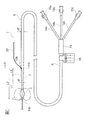
図1に示すように、本発明の一実施形態に係る内視鏡用処置具としての結石除去用バルーンカテーテル1は、カテーテルチューブ5と、バルーン(処置部)2と、カバー13と、3つの枝管14a〜14cと、3つのハブ15a〜15cとから構成されている。
As shown in FIG. 1, a calculus removal balloon catheter 1 as an endoscope treatment tool according to an embodiment of the present invention includes a
結石除去用バルーンカテーテル1のカテーテルチューブ5は、可撓性材料によって形成されたチューブであって、経内視鏡的に体内に挿入される側の端部である遠位端部7と、その他端側に位置する近位端部6とを有している。このカテーテルチューブ5における近位端部6の外径d2は、通常、1.0〜4.2mmであり、全長は、通常、500〜2500mmである。また、カテーテルチューブ5の材料は、可撓性を有する材料であれば特に限定されないが、高分子材料であることが好ましく、なかでも、ポリアミド樹脂あるいはポリアミド系エラストマーであることが特に好ましい。
The
カテーテルチューブ5の内部には、図2に示すように、バルーンルーメン8と、造影剤ルーメン9と、主ルーメン10とが形成されている。すなわち、カテーテルチューブ5は、多ルーメンチューブで構成してある。バルーンルーメン8は、バルーン2を膨張させるために用いる空気などの流体をバルーン2内部に送るための流路となるルーメンであり、カテーテルチューブ5の近位端から、カテーテルチューブ5の遠位端部7にバルーン2の内部に位置するように設けられた開口である流体導出口11まで貫通している。
As shown in FIG. 2, a
造影剤ルーメン9は、結石の位置を確認するなどの目的で、体内のX線造影を行う場合に、造影剤の流路として用いるルーメンである。この造影剤ルーメン9は、カテーテルチューブ5の近位端から、カテーテルチューブ5の遠位端部7の噴出口12まで貫通している。噴出口12は、バルーン2の外側に設けられた開口であり、本実施形態では、バルーン2より近位側に位置するように噴出口12が設けられている。
The
主ルーメン10は、カテーテルチューブ5の近位端から遠位端まで貫通しているが、図1に示す近位側ワイヤ挿通孔10aを境に、遠位側と近位側とでは、その機能が異なる。すなわち、主ルーメン10の遠位端開口は、遠位側ワイヤ挿通孔10bとして、バルーン2の遠位側に位置するチューブ5の遠位端に形成してあり、近位側ワイヤ挿通孔10aと遠位側ワイヤ挿通孔10bとの間に位置する主ルーメン10の遠位側主ルーメン10c(図2および図5E参照)がワイヤルーメン(遠位側ワイヤ通路)として機能する。また、図5Eに示す近位側ワイヤ挿通孔10aよりも、近位側に位置する主ルーメン10の近位側主ルーメン10dは、たとえばスタイレットなどを挿入するためのルーメンとして機能する。なお、スタイレットは、カテーテルチューブ5の剛性を増して、結石除去用バルーンカテーテル1の内視鏡や体内に対する挿入性を向上させる目的などに用いられ、たとえば、ステンレス鋼などの金属などで構成される線状体(撚り線または真直線など)または棒状体である。
The
図1に示すように、近位側ワイヤ挿通孔10aは、バルーン2よりも近位側で、カテーテルチューブ5の長手方向に沿っての途中位置であって、細径にされている遠位端部7よりも近位側で、外径d2を有する位置に形成してある。近位側ワイヤ挿通孔10aと遠位側ワイヤ挿通孔10bとの間の長さL2は、細径にされている遠位端部7の長手方向長さL1よりも大きく、好ましくは35〜800mmである。また、L2−L1=L3の長さは、好ましくは5〜400mmである。
As shown in FIG. 1, the proximal-side
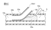
図5Eに示すように、近位側ワイヤ挿通孔10aから近位端方向に向かうルーメン10は、硬化された充填物40により閉塞してあり、充填物40により、主ルーメン10が、遠位側主ルーメン10cと近位側主ルーメン10dとの二つに分離され、相互に連通しないようになっている。近位側ワイヤ挿通孔10aから遠位端方向に向かう遠位側主ルーメン10cが、ワイヤ20を挿通可能な遠位側ワイヤ通路として利用可能になっている。硬化された充填物40には、近位側ワイヤ挿通孔10aから遠位側主ルーメン10cに向けてワイヤ20を案内し易くするための傾斜面42が形成してある。傾斜面42は、遠位側主ルーメン10cから近位側ワイヤ挿通孔10aに向けてワイヤ20を案内し易くする。
As shown in FIG. 5E, the
図5Eに示すような構造を実現するためには、たとえば、まず図5Aに示すように、カテーテルチューブ5の長手方向の所定位置(図1に示すL2の位置)に、主ルーメン10にのみ連通する近位側ワイヤ挿通孔10aを形成する。挿通孔10aの内径は、図5Bに示す仮チューブ30(仮芯材)の外径と略同一であり、仮チューブ30が挿通孔10aの内部に密着して入り込む程度の大きさである。
In order to realize the structure shown in FIG. 5E, for example, as shown in FIG. 5A, first, only the
また同時に、近位側ワイヤ挿通孔10aから近位端方向に所定距離L4で離れた位置に、主ルーメン10にのみ連通する充填用孔10eを形成する。充填用孔10eの内径は、特に限定されず、そこから流動状態の硬化前充填物40a(図5C参照)を充填できる程度の大きさであれば良い。また所定距離L4は、0を超えるものであれば特に限定されないが、充填物40aの充填量を減らすためには、好ましくは、2〜20mmである。
At the same time, a filling
硬化前充填物40aとしては、特に限定されず、注入後に硬化可能な充填物であれば良く、たとえばアクリレート系紫外線硬化性樹脂やエポキシ系紫外線硬化性樹脂などの紫外線硬化性樹脂、エポキシ系熱硬化性樹脂、フェノール系熱硬化性樹脂、ポリエステル系熱硬化性樹脂などの熱硬化性樹脂、エポキシ系二液常温硬化性樹脂、アクリル系二液常温硬化性樹脂などの二液常温硬化性樹脂、酢酸ビニル系溶剤揮散型接着剤などの溶剤揮散型接着剤、シアノアクリレート系湿気硬化型接着剤などの湿気硬化型接着剤などが例示される。
The
図5Bに示すように、仮チューブ30の遠位端30bが主ルーメン10の遠位側主ルーメン10cに位置し、近位端30aが近位側ワイヤ挿通孔10aからはみ出すように、仮チューブ30を近位側ワイヤ挿通孔10aの内部に挿入する。その後に、図5Cに示すように、流動状態の硬化前充填物40aを、充填用孔10eから主ルーメン10の仮チューブ30よりも近位端側に充填する。なお、図5Bおよび図5Cに示す実施形態では、主ルーメン10に挿入する仮芯材として、チューブ状の仮チューブ30を用いているが、仮芯材は中実のものであってもよい。
As shown in FIG. 5B, the
本実施形態では、仮芯材として用いられる仮チューブ30は、長手方向に沿って均一な外径および内径の柔軟性に優れた短チューブで構成してあり、たとえば、ポリテトラフルオロエチレンなどのフッ素樹脂、ポリアミド樹脂、ポリアミド系エラストマー、ポリオレフィン系樹脂、ポリ塩化ビニル樹脂などの材質で構成される。好ましくは、仮芯材は、カテーテルチューブ5と異なり、図5Cに示す硬化前の充填物40aおよび図5Eに示す硬化後の充填部40に接着しない材質であることが好ましい。このような観点からは、仮芯材は、ポリテトラフルオロエチレンなどのフッ素樹脂、ポリオレフィン系樹脂などで構成されることが好ましい。
In the present embodiment, the
流動状態の硬化前充填物40aの充填量は、特に限定されないが、少なくとも主ルーメン10の内部に挿入された仮チューブ30の近位端側外周面から近位端方向に向かう主ルーメン10を完全に閉塞させるに十分な量であることが好ましい。また、図5Dに示すように、充填用孔10eを完全に塞ぎ、そこから多少盛り上がる程度の充填量であることが好ましい。また、近位側ワイヤ挿通孔10aと仮チューブ30との隙間から主ルーメン10の外側に盛り上がる程度の充填量でも良い。
The filling amount of the
次に、用いた硬化前充填物40aの種類に応じた硬化方法によって、充填物40aを硬化させ、近位側ワイヤ挿通孔10aから近位端方向に向かうルーメン10を、硬化された充填物40により閉塞する。次に、図5Dに示すように、硬化された充填物40を残し、仮チューブ30を近位側ワイヤ挿通孔10aから引き抜き、主ルーメン10から除去する。その結果、充填物40の遠位端側には、近位側ワイヤ挿通孔10aから主ルーメン10の遠位端方向に向けて傾斜する傾斜面42が仮チューブ30の外周面形状に沿って転写して形成される。
Next, the
なお、充填用孔10eから盛り上がっている充填物40の盛り上がり部44は除去しても良いが、そのまま残しても良い。また、近位側ワイヤ挿通孔10aの開口縁に付着してある充填物40の盛り上がり部46は、充填用孔10eの開口縁を保護するために、そのまま残しておいても良い。
The raised
本実施形態によれば、遠位側ワイヤ通路として利用される遠位側主ルーメン10c内にカテーテルチューブ5と別途のチューブを設けることなく操作性に優れた結石除去用バルーンカテーテル1を製造することができる。
According to the present embodiment, the calculus removing balloon catheter 1 having excellent operability is manufactured without providing the
図3および図4に示すバルーンルーメン8、造影剤ルーメン9および主ルーメン10の断面形状は、いずれも限定されず、それぞれをカテーテルチューブ5内に効率的に配置できる形状とすればよい。ただし、主ルーメン10については、一般的なガイドワイヤ20の断面と同様に断面形状が円形であることが好ましい。また、バルーンルーメン8の断面積は、0.03〜0.5mm2 、造影剤ルーメン9の断面積は、0.08〜1.0mm2 、主ルーメン10の断面積は、0.5〜2.0mm2 であることがそれぞれ好ましい。
The cross-sectional shapes of the
結石除去用バルーンカテーテル1のバルーン2は、カテーテルチューブ5の遠位端部に流体導出口11を覆うように取り付けられている。このバルーン2は伸縮性材料により形成されていて、カテーテルチューブ5のバルーンルーメン8を介して、内部に流体が導入されることにより膨張されるようになっている。この膨張したバルーン2によって、結石を掻き出したり、押し出したりして、体内の結石の除去を行うことができる。
The
バルーン2を形成する伸縮性材料としては、100%モジュラス(JIS K 6251に準拠して測定した値)が、0.1〜10Mpaであるものが好ましく、1〜5Mpaであるものが特に好ましい。100%モジュラスが小さすぎると、バルーン2の強度が不足するおそれがあり、大きすぎると、バルーン2を十分な大きさに膨張できなくなるおそれがある。また、バルーン2を形成するために好適な伸縮性材料の具体例としては、天然ゴム、シリコーンゴム、ポリウレタンエラストマーなどが挙げられる。
The stretchable material forming the
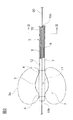
図2に示すように、バルーン2は、全体として筒状であり、その両端部にカテーテルチューブ5の外周面と接合される接合部4が形成されていて、その両端の接合部4の間には、内部に流体が導入されることにより膨張する膨張部3が形成されている(図2において、外力を受けない状態の膨張部3は実線で示し、内部に流体が導入されて膨張した膨張部3aは二点鎖線で示してある)。
As shown in FIG. 2, the
このバルーン2の膨張部3は、外力を受けない状態において、カテーテルチューブ5の中心軸を回転軸としてカテーテルチューブ5の外方に向かって凸の曲線を回転させてなる回転体形状に形成されている。すなわち、カテーテルチューブ5に取り付けられたバルーン2の膨張部3は、その内部と外部とで圧力が釣り合った状態(バルーン2を膨張させるための流体をバルーン2の内部に送り込んでいない状態)において、上述したような回転体形状になっている。
The
バルーン2の膨張部3がこのような形状に形成されることによって、従来の外力を受けない状態において円筒形であるバルーンに比して、バルーン2を大きな外径に膨張させることが可能となる。なお、回転体形状の母線となる曲線は、カテーテルチューブ5の外方に向かって凸の曲線であれば特に限定されず、いかなる曲線であっても良いが、カテーテルチューブ5の中心軸と同一平面上にある曲線であることが好ましい。
By forming the inflating
外力を受けない状態におけるバルーン2の膨張部3は、その最大外径が、最小外径の110〜250%であることが好ましい。また、バルーン2の膨張部3の長さ(カテーテルチューブ5の長手方向に沿った長さ)は、5〜20mmが好ましく、肉厚は、0.10〜0.50mmであることが好ましい。
The
結石除去用バルーンカテーテル1において、造影剤を噴出するための噴出口を設ける際は、バルーン2の近位端から近位側に向かって10mm以内(より好ましくは5mm以内)の位置においてカテーテルチューブ5の表面に設けることが好ましい。この位置に噴出口12を設けておけば、バルーン2を膨張させることにより体内管腔を塞いでから、造影剤を噴出口12から噴出させることによって、膨張したバルーン2より手前側に位置する体内管腔を効率的に造影することできるからである。ただし、噴出口は、バルーン2の遠位端から遠位側に向かって10mm以内(より好ましくは5mm以内)の位置において、カテーテルチューブ5の表面に設けてもよい。バルーン2よりも遠位側に噴出口を設けた場合には、体内管腔においてバルーン2を膨張させる前に、造影剤を噴出口から噴出させて、体内管腔を造影して体内管腔内の状況を確認することで、より適切な位置にバルーン2を挿入しやすくなる。
When the calculus removing balloon catheter 1 is provided with an ejection port for ejecting a contrast medium, the
バルーン2の膨張部3の両端側に位置する接合部4の形状は、カテーテルチューブ5の遠位端部7に接合可能な形状であれば特に限定されないが、円筒形であることが好ましい。バルーン2の接合部4が円筒形である場合、その内径はカテーテルチューブ5の外径とほぼ等しいことが好ましく、長さは、0.5〜5mmであることが好ましい。また、バルーン2の接合部4の肉厚は、特に限定されず、たとえば、膨張部3と実質的に等しくすれば良い。なお、バルーン2の接合部4とカテーテルチューブ5の遠位端部7とを接合する手法は、特に限定されず、たとえば、接着剤による接着、熱融着、溶剤による溶着、超音波溶着などを挙げることができる。
The shape of the
上記したような形状を有するバルーン2を製造する方法は特に限定されず、伸縮性材料の製膜方法として公知の方法を用いればよいが、ディッピング成形法を用いることが好ましい。ディッピング成形法では、伸縮性材料と必要に応じて各種添加剤を溶剤に溶解して溶液あるいは懸濁液とし、この溶液(懸濁液)に所望するバルーンの形状と略等しい外形を有する型を浸漬させて型の表面に溶液(懸濁液)を塗布し、溶剤を蒸発させて型の表面に被膜を形成させる。この浸漬と乾燥を繰り返すことにより所望の肉厚を有するバルーンを製膜することができる。なお、伸縮性材料の種類により、必要に応じて、製膜後、架橋を行う。
A method for manufacturing the
結石除去用バルーンカテーテル1では、図1に示す実施形態のように、バルーン2が取り付けられるカテーテルチューブ5の遠位端部7が、カテーテルチューブ5の他の部分(近位端部6)よりも外径が小さくなっている細径部となっていることが好ましい。結石除去用バルーンカテーテル1では、バルーン2を取り付ける箇所のカテーテルチューブ5(遠位端部7)が細径であっても、バルーンを十分に大きく膨張させることが可能であり、また、カテーテルチューブ5の近位端部6の剛直性をある程度保ちながら、遠位端部7を細径にして柔軟にすることによって、結石除去用バルーンカテーテル1の操作性が向上するからである。この場合において、カテーテルチューブ5の遠位端部7の外径d1は、近位端部6の外径d2の50〜95%であることが好ましく、60〜90%であることが特に好ましい。
In the calculus removing balloon catheter 1, as in the embodiment shown in FIG. 1, the distal end portion 7 of the
カテーテルチューブ5の遠位端部7を、近位端部6より細径にする手法は特に限定されないが遠位端部7と近位端部6との境界位置のカテーテルチューブ5を、遠位端に向かって細くなるテーパー状にすることが好ましい。また、遠位端部7を、近位端部6より細径にする他の手法としては、遠位端部7と近位端部6との間に段差を設けることが挙げられる。細径にされている遠位端部7の長手方向の長さL1は、好ましくは、30〜400mmである。
The method of making the distal end 7 of the
結石除去用バルーンカテーテル1の枝管14a〜14cは、カテーテルチューブ5のバルーンルーメン8に流体を送る操作や、造影剤ルーメン9に造影剤を注入する操作、あるいは、スタイレットを主ルーメン10の近位端側に挿入する操作が容易になるように、それぞれのルーメンと接続されたチューブである。
The
枝管14a〜14cの材質としては、特に限定されないが、高分子材料を用いることが好ましい。また、枝管14a〜14cとカテーテルチューブ5の各ルーメンとの接続方法は、特に限定されないが、たとえば、枝管14a〜14cの遠位端部をテーパー状に成形し、その外周面に接着剤を塗布して、その端部をカテーテルチューブ5のルーメンに挿入することにより、接着すればよい。
The material of the
結石除去用バルーンカテーテル1のハブ15a〜15cは、枝管14a〜14cの近位端側に接続される部材である。たとえばハブ15aおよび枝管14aは、図2に示すバルーンルーメン8に連通してあり、そこへハブ15aからバルーン拡張用流体を導入または導出可能になっている。また、ハブ15cおよび枝管14cは、図2に示す造影用ルーメン9に連通してあり、そこへハブ15cから造影用流体を導入または導出可能になっている。ハブ15bおよび枝管14bは、図5Eに示す近位側主ルーメン10dに連通してあり、そこへハブ15bからスタイレットを導入または導出可能になっている。ハブ15a〜15cの材質としては、特に限定されないが、透明な高分子材料を用いることが好ましい。
The
図1に示す結石除去用バルーンカテーテル1のカバー13は、カテーテルチューブ5と枝管14a〜14cとの接続部を補強して保護するために、その接続部を覆うように設けられる。カバー13の形状は特に限定されないが、通常、箱型あるいは筒型である。カバー13の材質としては、特に限定されないが、高分子材料を用いることが好ましい。また、熱収縮チューブをカバー13として用いることも可能である。
The
カバー13の遠位端側には、カテーテルチューブ5の外周に、タグ16が取り付けてある。タグ16には、たとえば、どれくらいのエア容量でバルーン2がどれくらいの外径に膨らむかなど、当該バルーンカテーテル1に特有の情報が表示してある。
A
次に、本実施形態の結石除去用バルーンカテーテル1の使用例として、胆管より胆石を除去する例について説明する。 Next, an example of removing gallstones from the bile duct will be described as an example of use of the calculus removal balloon catheter 1 of the present embodiment.
まず、内視鏡を体内に挿入し、内視鏡の先端を胆管の入り口(十二指腸乳頭)の近傍に位置させる。次いで、必要に応じてカニュレーション用カテーテルなどを用い、内視鏡のチャネルを介して、ガイドワイヤ20を患者の体内に挿入し、ガイドワイヤ20の遠位端を胆管内まで導く。この際、ガイドワイヤ20の近位端側の部分が、用いる結石除去用バルーンカテーテル1における近位側ワイヤ挿通孔10aと遠位側ワイヤ挿通孔10bとの間の長さ(距離L2)より少し長い程度の長さで内視鏡から出るように、予め適切な長さのガイドワイヤ20を用いるようにする。次いで、必要に応じてハブ15bおよび枝管14bを介して近位側主ルーメン10dにスタイレットを挿入すると共に、近位側ワイヤ挿通孔10aと遠位側ワイヤ挿通孔10bとの間の遠位側主ルーメン(ワイヤルーメン)10cに、遠位側ワイヤ挿通孔10b側からガイドワイヤ20を通す。その後に、バルーン2を膨張させない状態で、カテーテルチューブ5の遠位端側から、内視鏡のチャネルを介して、結石除去用バルーンカテーテル1をガイドワイヤ20に沿わせて体内に挿入し、カテーテル1の遠位端部を胆管内まで導く。
First, the endoscope is inserted into the body, and the distal end of the endoscope is positioned in the vicinity of the bile duct entrance (duodenal papilla). Next, using a cannulation catheter as necessary, the
次いで、胆管の奥部まで、カテーテル1を押し進めてから、シリンジなどにより、ハブ15a、枝管14aおよびバルーンルーメン8を介して、バルーン2内に空気を送り込んで、バルーン2を膨張させる。
Next, the catheter 1 is pushed forward to the deep part of the bile duct, and then the
次いで、シリンジなどにより、ハブ15c、枝管14c、造影剤ルーメン9を介して、造影剤を噴出口12へ送り込んで、造影剤を噴出させて、胆管内のX線造影を行い、胆石の様子を確認する。続いて、バルーン2を膨張させた状態のまま、カテーテル1を引き戻すと、バルーン2によって胆石を十二指腸乳頭から胆管外へ掻き出すことができる。
Next, the contrast medium is sent to the
この際、本実施形態のカテーテル1では、バルーン2を十分な大きさに膨張できるので、胆管内壁とバルーン2との間に隙間が生じにくく、胆石の掻き出しを容易に行うことができる。なお、胆管外に掻き出された胆石は、通常、自然に体外まで排出される。すなわち、本実施形態のバルーンカテーテル1によれば、胆石などの結石を、バルーン2を用いて迅速に体外に排出することが容易になる。
At this time, in the catheter 1 of the present embodiment, since the
また、バルーンカテーテル1を他のバルーンカテーテルなどの他の内視鏡用処置具と交換する必要が生じた際には、ガイドワイヤ20の遠位端を体内に残した状態で、バルーンカテーテル1のみを、ガイドワイヤ20に沿って、体外に引き出す。その際に、ガイドワイヤ20は、カテーテルチューブ5の途中に位置する近位側ワイヤ挿通孔10aから遠位側ワイヤ挿通孔10bまでの比較的短い距離L2で、遠位側主ルーメン10内に通してあるため、カテーテル1の取り出しが容易である。
When it is necessary to replace the balloon catheter 1 with another endoscopic treatment tool such as another balloon catheter, only the balloon catheter 1 is left with the distal end of the
すなわち、ガイドワイヤ20の近位端側では、少なくともカテーテルチューブ5の遠位側ワイヤ挿通孔10bから近位側ワイヤ挿通孔10aまでに対応する長さより少し長めに、内視鏡から引き出しておけば良くなる。その結果、ガイドワイヤ20を遠位側主ルーメン10cに挿入する作業のみでなく、バルーンカテーテル1をワイヤ20に沿って抜き取る作業が容易になり、ハンドリング性が向上する。また、バルーンカテーテル1の他の内視鏡用処置具への交換も容易になる。さらに、内視鏡から引き出しておくガイドワイヤ20の長さを短くできるため、その衛生管理も容易になる。
That is, at the proximal end side of the
さらに本実施形態のバルーンカテーテル1では、近位側ワイヤ挿通孔10aから主ルーメン10の遠位端方向に向けてワイヤ20を案内し易くするための傾斜面42が、硬化充填物40に形成してあることから、ガイドワイヤ20の近位端を遠位側ワイヤ挿通孔10cから押し込むのみで、ガイドワイヤ20の近位端は、遠位側ワイヤ通路10cを通して、近位側ワイヤ挿通孔10aに向けて案内され、そこからガイドワイヤ20を引き出す作業が容易になる。
Furthermore, in the balloon catheter 1 of the present embodiment, an
また、近位側ワイヤ挿通孔10aの近くに位置する主ルーメン10内に、硬化充填物40aが充填してあることから、近位側ワイヤ挿通孔10aの近くが補強され、その部分でのキンクを有効に防止することができる。
Further, since the
さらに本実施形態では、仮チューブ30の近位端よりもさらに近位側に位置する近位側主ルーメン10dには、スタイレットが着脱自在に挿入されるため、カテーテルチューブ5の近位端部の剛性が増し、ガイドワイヤ20に沿ってのバルーンカテーテル1の送り込み特性が向上する。
Furthermore, in the present embodiment, since the stylet is detachably inserted into the proximal
また本実施形態では、近位側ワイヤ挿通孔10aの近位側に位置するカテーテルチューブ5の外周面には、硬化する前の流動する充填物40aを、ルーメン10の内部に充填するための充填用孔10eが形成してあり、充填用孔10eは、硬化後の充填物40により閉塞される。このような構成にすることで、近位側ワイヤ挿通孔10aの近くにおいて、カテーテルチューブ1の主ルーメン10の内部に硬化前充填物40aを充填する作業が容易になる。また、充填用孔10eは、硬化後の充填物40により閉塞されていることから、充填孔10eと主ルーメン10の内部とが連通することもない。
Further, in the present embodiment, the outer circumferential surface of the
また、充填用孔10eの開口縁は、硬化された後の充填物40の一部44により補強されることになる。さらに、近位側ワイヤ挿通孔10aの開口縁も、硬化された後の充填物40の一部により補強されることになる。
Further, the opening edge of the filling
また本実施形態では、バルーン2がカテーテルチューブ5の遠位端部に装着してあり、バルーン2の内部が、カテーテルチューブ5の主ルーメン10とは別のバルーンルーメン8に連通してある。このような構成のバルーンカテーテル1によれば、胆石などの結石を、バルーン2を用いて迅速に体外に排出することが容易になる。
In this embodiment, the
さらに本実施形態では、遠位側ワイヤ通路として利用される遠位側主ルーメン10cには、カテーテルチューブ5と別途のチューブを挿入する必要がない。したがって、バルーンカテーテル1の遠位端部における柔軟性を向上させることができる。したがって、体内への内視鏡用処置具の挿入特性が向上する。
Furthermore, in this embodiment, it is not necessary to insert the
なお、本発明は、上述した実施形態に限定されるものではなく、本発明の範囲内で種々に改変することができる。 The present invention is not limited to the above-described embodiment, and can be variously modified within the scope of the present invention.
たとえば、上述した実施形態では、結石除去用バルーンカテーテル1が備えるバルーンは1つであるが、複数のバルーンを備えていても良い。また、カテーテルチューブ5において、造影剤ルーメン9は必ずしも設ける必要はなく、前述した機能以外の機能を有する他のルーメンを形成することも可能である。また、造影剤ルーメン9に、造影剤を噴出口12へ送り込むこと以外の機能を果たすようさせても良い。たとえば、造影剤ルーメン9に生理食塩水などの流体を勢いよく送り込んで、流体を噴出口12から噴出させて、その流体によって結石などを押し流す機能を果たさせても良い。この場合、流体がカテーテルの中心軸に対して近位端方向側に斜めに流体が噴出されるように、噴出口12を、カテーテルチューブ5の壁面に対して斜めに形成することが好ましい。
For example, in the above-described embodiment, the calculus removing balloon catheter 1 includes one balloon, but may include a plurality of balloons. In the
また、上述した実施形態では、カテーテルチューブ5を多ルーメンチューブで構成してあるが、シングルルーメンのカテーテルチューブを用いても良い。また、シングルルーメンのカテーテルチューブの内部に、他のチューブを挿入させても良い。
In the above-described embodiment, the
また、上述した実施形態では、カテーテルチューブ5の遠位端部7の外径を近位端部より細径としていたが、必ずしもこれに限定されず、たとえば、遠位端部と近位端部の外径を実質的に等しくしてもよい。
Moreover, in embodiment mentioned above, although the outer diameter of the distal end part 7 of the
また、上述した実施形態では、バルーン2の膨張部3は、カテーテルチューブ5の中心軸を対称軸する略回転対称形状に膨らむようにしていたが、特開2008−194166号公報に記載されるように、膨張部3が、カテーテルチューブ5の軸心に対して偏心して膨らむように、バルーン2の周方向の少なくとも一部に、偏心膨張手段を設けてもよい。
In the above-described embodiment, the
さらに、結石除去用バルーンカテーテル1は、体内から結石を除去するために用いられるものであれば良く、胆石の除去用途に限定されるものではない。また、本発明の内視鏡用処置具における処置部は、バルーン2以外のものでも良く、結石除去用途以外のバルーンカテーテル、あるいはバルーンカテーテル以外の内視鏡用処置具でもよい。
Furthermore, the calculus removing balloon catheter 1 is not limited to the use for removing gallstones as long as it is used for removing calculus from the body. Further, the treatment section in the endoscope treatment tool of the present invention may be other than the
1… 結石除去用バルーンカテーテル(内視鏡用処置具)
2… バルーン(処置部)
3… 膨張部
4… 接合部
5… カテーテルチューブ
6… 近位端部
7… 遠位端部
8… バルーンルーメン
9… 造影剤ルーメン
10… 主ルーメン
10a… 近位側ワイヤ挿通孔
10b… 遠位側ワイヤ挿通孔
10c… 遠位側主ルーメン
10d… 近位側主ルーメン
10e… 充填用孔
11… 流体導出口
12… 噴出口
13… カバー
14a〜14c… 枝管
15a〜15c… ハブ
20… ガイドワイヤ
30… 仮チューブ(仮芯材)
30a… 近位端
30b… 遠位端
40… 硬化後の充填物
40a… 硬化前の充填物
1 ... Balloon catheter for calculus removal (endoscopic instrument)
2 ... Balloon (treatment section)
DESCRIPTION OF
30a ...
Claims (7)
前記カテーテルチューブの遠位端部に具備してある処置部と、を有する内視鏡用処置具であって、
前記カテーテルチューブの遠位端に、前記ルーメンに通じる遠位側ワイヤ挿通孔が形成してあり、
前記処置部よりも近位側で、前記カテーテルチューブの長手方向に沿っての途中位置には、前記ルーメンに通じる近位側ワイヤ挿通孔が形成してあり、
前記近位側ワイヤ挿通孔から近位端方向に向かう前記ルーメンが、硬化された充填物により閉塞してあり、
前記近位側ワイヤ挿通孔から遠位端方向に向かう前記ルーメンが、ワイヤが挿通可能な遠位側ワイヤ通路として利用可能になっており、
前記充填物には、前記遠位側ワイヤ通路から前記近位側ワイヤ挿通孔に向けて前記ワイヤを案内し易くするための傾斜が形成してある内視鏡用処置具。 A catheter tube having a lumen formed along the longitudinal direction;
A treatment portion provided at a distal end portion of the catheter tube,
A distal wire insertion hole leading to the lumen is formed at the distal end of the catheter tube,
A proximal wire insertion hole leading to the lumen is formed at a midway position along the longitudinal direction of the catheter tube on the proximal side of the treatment portion.
The lumen from the proximal wire insertion hole toward the proximal end is closed with a hardened filler;
The lumen from the proximal wire insertion hole toward the distal end is usable as a distal wire passage through which a wire can be inserted,
A treatment instrument for an endoscope, wherein the filling is formed with an inclination to facilitate guiding the wire from the distal wire passage toward the proximal wire insertion hole.
前記充填用孔は、硬化後の前記充填物により閉塞されている請求項1に記載の内視鏡用処置具。 On the outer peripheral surface of the catheter tube located on the proximal end side of the proximal side wire insertion hole, a filling hole for filling the inside of the lumen with the filling material that flows before being cured is formed. Yes,
The treatment instrument for an endoscope according to claim 1, wherein the filling hole is closed by the filling material after curing.
前記バルーン部の内部が、前記カテーテルチューブの前記ルーメンとは別のバルーンルーメンに連通してある請求項1〜4のいずれかに記載の内視鏡用処置具。 In the treatment section, a balloon is attached to the distal end of the catheter tube,
The treatment instrument for an endoscope according to any one of claims 1 to 4, wherein the inside of the balloon portion communicates with a balloon lumen different from the lumen of the catheter tube.
前記カテーテルチューブの遠位端部に具備してある処置部と、を有する内視鏡用処置具を製造する方法であって、
前記処置部よりも近位側で、前記カテーテルチューブの長手方向に沿っての途中位置に、前記ルーメンに通じる近位側ワイヤ挿通孔を形成する工程と、
前記近位側ワイヤ挿通孔から遠位端方向に向かう前記ルーメンに向けて仮芯材を挿入する工程と、
前記近位側ワイヤ挿通孔の近くであって、前記仮芯材の外周部から前記近位端方向に向かう前記ルーメンの一部に、流動可能な充填物を流し込み、当該充填物を硬化させて、前記近位側ワイヤ挿通孔から近位端方向に向かう前記ルーメンを、硬化された充填物により閉塞する工程と、
硬化された前記充填物を残し、前記仮芯材を前記ルーメンから除去する工程と、を有する内視鏡用処置具の製造方法。 A catheter tube having a lumen formed along the longitudinal direction;
A treatment portion provided at a distal end portion of the catheter tube, and a method for manufacturing a treatment instrument for an endoscope,
Forming a proximal wire insertion hole leading to the lumen at a midpoint along the longitudinal direction of the catheter tube at a position proximal to the treatment portion;
Inserting a temporary core toward the lumen from the proximal wire insertion hole toward the distal end;
A flowable filler is poured into a part of the lumen that is near the proximal-side wire insertion hole and extends from the outer peripheral portion of the temporary core member toward the proximal end, and the filler is cured. Closing the lumen from the proximal wire insertion hole toward the proximal end with a hardened filling;
Leaving the cured filling, and removing the temporary core from the lumen.
Priority Applications (1)
| Application Number | Priority Date | Filing Date | Title |
|---|---|---|---|
| JP2015137080A JP6519368B2 (en) | 2015-07-08 | 2015-07-08 | Treatment tool for endoscope and method of manufacturing the same |
Applications Claiming Priority (1)
| Application Number | Priority Date | Filing Date | Title |
|---|---|---|---|
| JP2015137080A JP6519368B2 (en) | 2015-07-08 | 2015-07-08 | Treatment tool for endoscope and method of manufacturing the same |
Publications (2)
| Publication Number | Publication Date |
|---|---|
| JP2017018209A true JP2017018209A (en) | 2017-01-26 |
| JP6519368B2 JP6519368B2 (en) | 2019-05-29 |
Family
ID=57888952
Family Applications (1)
| Application Number | Title | Priority Date | Filing Date |
|---|---|---|---|
| JP2015137080A Active JP6519368B2 (en) | 2015-07-08 | 2015-07-08 | Treatment tool for endoscope and method of manufacturing the same |
Country Status (1)
| Country | Link |
|---|---|
| JP (1) | JP6519368B2 (en) |
Cited By (3)
| Publication number | Priority date | Publication date | Assignee | Title |
|---|---|---|---|---|
| WO2018151051A1 (en) * | 2017-02-15 | 2018-08-23 | オリンパス株式会社 | Medical catheter and method for producing medical tube |
| CN110339461A (en) * | 2019-07-15 | 2019-10-18 | 温州医科大学附属第一医院 | The lower foley's tube that can cross seal wire of endoscope guidance |
| CN110339463A (en) * | 2019-07-15 | 2019-10-18 | 温州医科大学附属第一医院 | Microendoscopic bootstrap foley's tube |
Citations (5)
| Publication number | Priority date | Publication date | Assignee | Title |
|---|---|---|---|---|
| JPH0563551U (en) * | 1992-02-07 | 1993-08-24 | オリンパス光学工業株式会社 | Balloon catheter |
| JPH06507811A (en) * | 1991-06-13 | 1994-09-08 | ジャング,ジー.,デビッド | Universal mode vascular catheter system |
| WO1997029800A1 (en) * | 1996-02-13 | 1997-08-21 | Cardiovascular Dynamics, Inc. | Hybrid catheter shaft |
| JP2000116802A (en) * | 1998-10-14 | 2000-04-25 | Terumo Corp | Catheter for radiotherapy and catheter assembly for radiotherapy |
| JP2007503869A (en) * | 2003-09-02 | 2007-03-01 | ボストン サイエンティフィック リミテッド | CATHETER PROVIDED WITH INTEGRATED TIP-SIDE GUIDEWIRE PORT AND MANUFACTURING METHOD |
-
2015
- 2015-07-08 JP JP2015137080A patent/JP6519368B2/en active Active
Patent Citations (5)
| Publication number | Priority date | Publication date | Assignee | Title |
|---|---|---|---|---|
| JPH06507811A (en) * | 1991-06-13 | 1994-09-08 | ジャング,ジー.,デビッド | Universal mode vascular catheter system |
| JPH0563551U (en) * | 1992-02-07 | 1993-08-24 | オリンパス光学工業株式会社 | Balloon catheter |
| WO1997029800A1 (en) * | 1996-02-13 | 1997-08-21 | Cardiovascular Dynamics, Inc. | Hybrid catheter shaft |
| JP2000116802A (en) * | 1998-10-14 | 2000-04-25 | Terumo Corp | Catheter for radiotherapy and catheter assembly for radiotherapy |
| JP2007503869A (en) * | 2003-09-02 | 2007-03-01 | ボストン サイエンティフィック リミテッド | CATHETER PROVIDED WITH INTEGRATED TIP-SIDE GUIDEWIRE PORT AND MANUFACTURING METHOD |
Cited By (6)
| Publication number | Priority date | Publication date | Assignee | Title |
|---|---|---|---|---|
| WO2018151051A1 (en) * | 2017-02-15 | 2018-08-23 | オリンパス株式会社 | Medical catheter and method for producing medical tube |
| CN110234384A (en) * | 2017-02-15 | 2019-09-13 | 奥林巴斯株式会社 | The manufacturing method of catheter tube for medical treatment and medical pipe |
| CN110234384B (en) * | 2017-02-15 | 2022-03-01 | 奥林巴斯株式会社 | Medical catheter and method for manufacturing medical tube |
| CN110339461A (en) * | 2019-07-15 | 2019-10-18 | 温州医科大学附属第一医院 | The lower foley's tube that can cross seal wire of endoscope guidance |
| CN110339463A (en) * | 2019-07-15 | 2019-10-18 | 温州医科大学附属第一医院 | Microendoscopic bootstrap foley's tube |
| CN110339461B (en) * | 2019-07-15 | 2024-04-16 | 南京康友医疗科技有限公司 | Balloon catheter capable of passing guide wire under guidance of endoscope |
Also Published As
| Publication number | Publication date |
|---|---|
| JP6519368B2 (en) | 2019-05-29 |
Similar Documents
| Publication | Publication Date | Title |
|---|---|---|
| US20210322035A1 (en) | Increased axial load carrying sheathed irrigating balloon catheter | |
| JP6859950B2 (en) | Endoscopic treatment tool | |
| US20220401710A1 (en) | Reinforced Balloon Catheter | |
| CN101730563B (en) | Spiral balloon catheter | |
| US20180280041A1 (en) | Increased axial load carrying sheathed irrigating balloon catheter | |
| JP5438025B2 (en) | Two-part extraction balloon | |
| JP2020522310A (en) | Blockage removal device, system and method | |
| EP3233173B1 (en) | Catheter patency systems and methods | |
| WO2017111164A1 (en) | Endoscope treatment instrument | |
| JP6519368B2 (en) | Treatment tool for endoscope and method of manufacturing the same | |
| JP2017113271A (en) | Endoscopic treatment instrument | |
| JP2009542413A (en) | Vascular catheter apparatus and method | |
| JP2012205697A (en) | Catheter and production method thereof | |
| JP5135816B2 (en) | Balloon catheter for stone removal | |
| JP2016198355A (en) | Treatment instrument for endoscope | |
| JP7205048B2 (en) | Manufacturing method of balloon catheter for removal of foreign body | |
| JP2021084030A (en) | No-preparation balloon guide catheter | |
| JP5779885B2 (en) | Balloon catheter | |
| CN114599297A (en) | Balloon catheter for removing foreign matter | |
| JP4379226B2 (en) | Balloon catheter for stone removal | |
| JP2008194167A (en) | Balloon catheter for calculus removal | |
| JP2007229129A (en) | Balloon catheter | |
| EP2967600B1 (en) | Removal tool for use with endoscopic device | |
| US11213306B2 (en) | Catheter | |
| JP2009119104A (en) | Catheter for intestinal insertion |
Legal Events
| Date | Code | Title | Description |
|---|---|---|---|
| A621 | Written request for application examination |
Free format text: JAPANESE INTERMEDIATE CODE: A621 Effective date: 20180316 |
|
| A977 | Report on retrieval |
Free format text: JAPANESE INTERMEDIATE CODE: A971007 Effective date: 20181107 |
|
| A131 | Notification of reasons for refusal |
Free format text: JAPANESE INTERMEDIATE CODE: A131 Effective date: 20181113 |
|
| A601 | Written request for extension of time |
Free format text: JAPANESE INTERMEDIATE CODE: A601 Effective date: 20181225 |
|
| A521 | Request for written amendment filed |
Free format text: JAPANESE INTERMEDIATE CODE: A523 Effective date: 20190312 |
|
| TRDD | Decision of grant or rejection written | ||
| A01 | Written decision to grant a patent or to grant a registration (utility model) |
Free format text: JAPANESE INTERMEDIATE CODE: A01 Effective date: 20190326 |
|
| A61 | First payment of annual fees (during grant procedure) |
Free format text: JAPANESE INTERMEDIATE CODE: A61 Effective date: 20190408 |
|
| R150 | Certificate of patent or registration of utility model |
Ref document number: 6519368 Country of ref document: JP Free format text: JAPANESE INTERMEDIATE CODE: R150 |
|
| R250 | Receipt of annual fees |
Free format text: JAPANESE INTERMEDIATE CODE: R250 |
|
| R250 | Receipt of annual fees |
Free format text: JAPANESE INTERMEDIATE CODE: R250 |