JP2017016920A - Lever switch apparatus - Google Patents
Lever switch apparatus Download PDFInfo
- Publication number
- JP2017016920A JP2017016920A JP2015133588A JP2015133588A JP2017016920A JP 2017016920 A JP2017016920 A JP 2017016920A JP 2015133588 A JP2015133588 A JP 2015133588A JP 2015133588 A JP2015133588 A JP 2015133588A JP 2017016920 A JP2017016920 A JP 2017016920A
- Authority
- JP
- Japan
- Prior art keywords
- axis
- lever
- around
- magnet
- holder
- Prior art date
- Legal status (The legal status is an assumption and is not a legal conclusion. Google has not performed a legal analysis and makes no representation as to the accuracy of the status listed.)
- Pending
Links
Images


Classifications
-
- B—PERFORMING OPERATIONS; TRANSPORTING
- B60—VEHICLES IN GENERAL
- B60Q—ARRANGEMENT OF SIGNALLING OR LIGHTING DEVICES, THE MOUNTING OR SUPPORTING THEREOF OR CIRCUITS THEREFOR, FOR VEHICLES IN GENERAL
- B60Q1/00—Arrangement of optical signalling or lighting devices, the mounting or supporting thereof or circuits therefor
- B60Q1/02—Arrangement of optical signalling or lighting devices, the mounting or supporting thereof or circuits therefor the devices being primarily intended to illuminate the way ahead or to illuminate other areas of way or environments
- B60Q1/04—Arrangement of optical signalling or lighting devices, the mounting or supporting thereof or circuits therefor the devices being primarily intended to illuminate the way ahead or to illuminate other areas of way or environments the devices being headlights
- B60Q1/14—Arrangement of optical signalling or lighting devices, the mounting or supporting thereof or circuits therefor the devices being primarily intended to illuminate the way ahead or to illuminate other areas of way or environments the devices being headlights having dimming means
- B60Q1/1446—Arrangement of optical signalling or lighting devices, the mounting or supporting thereof or circuits therefor the devices being primarily intended to illuminate the way ahead or to illuminate other areas of way or environments the devices being headlights having dimming means controlled by mechanically actuated switches
- B60Q1/1453—Hand actuated switches
- B60Q1/1461—Multifunction switches for dimming headlights and controlling additional devices, e.g. for controlling direction indicating lights
- B60Q1/1469—Multifunction switches for dimming headlights and controlling additional devices, e.g. for controlling direction indicating lights controlled by or attached to a single lever, e.g. steering column stalk switches
Abstract
Description
本発明は、レバースイッチ装置に関する。 The present invention relates to a lever switch device.
従来の技術として、外レバーの揺動操作(左ターン操作、右ターン操作、パッシング操作及びディマ操作)に応じて回転する第一の回転体と第二の回転体を設け、この中央に装着された2つの磁石の磁気をそれぞれの磁石に対応して設けられた2つの磁気検出素子で検出すると共に、制御手段がこの検出信号から各回転体の回転角度を検出し、これに応じた操作信号を出力する構成を有するレバースイッチが知られている(特許文献1参照)。 As a conventional technique, a first rotating body and a second rotating body that rotate according to the swinging operation of the outer lever (left turn operation, right turn operation, passing operation, and dimmer operation) are provided and mounted at the center. In addition, the magnetism of the two magnets is detected by the two magnetism detecting elements provided corresponding to the respective magnets, and the control means detects the rotation angle of each rotating body from this detection signal, and the operation signal corresponding to this Is known (see Patent Document 1).
しかし、従来のレバースイッチは、揺動操作(左ターン操作、右ターン操作、パッシング操作及びディマ操作)を検出するため、2つの磁石を必要としており、製造コストの抑制が困難であると共に小型化が困難となっていた。 However, the conventional lever switch detects two swinging operations (left-turn operation, right-turn operation, passing operation and dimmer operation) and requires two magnets, making it difficult to reduce manufacturing costs and downsizing. Has become difficult.
従って、本発明の目的は、製造コストを抑制すると共に小型化することができるレバースイッチ装置を提供することにある。 Accordingly, an object of the present invention is to provide a lever switch device capable of reducing the manufacturing cost and reducing the size.
本発明の一態様は、交差する第1の軸及び第2の軸周りに回転する操作レバーと、第1のリンクを有し、操作レバーと一体となって第1の軸周りに回転すると共に操作レバーの第2の軸周りの回転が可能となるように操作レバーを保持する第1のホルダと、第2のリンクを有し、第1のホルダに取り付けられ、操作レバーの第2の軸周りの回転を第2のリンクの直線的な移動に変換する変換部と、周囲に磁場を生成すると共に第2のリンクが挿入される被挿入部を有し、被挿入部に挿入された第2のリンクの直線的な移動によって第3の軸周りに回転する磁場生成部と、第3の軸周りの回転が可能となるように磁場生成部を保持し、第1のホルダの第1のリンクと連結されて操作レバーの第1の軸周りの回転によって第3の軸と交差する第4の軸周りに磁場生成部と共に回転する第2のホルダと、磁場生成部の第4の軸周りの回転の検出を介して操作レバーの第1の軸周りの回転を検出する第1の磁気センサと、磁場生成部の第3の軸周りの回転の検出を介して操作レバーの第2の軸周りの回転を検出する第2の磁気センサと、を備えたレバースイッチ装置を提供する。 One aspect of the present invention includes an operation lever that rotates around a first axis and a second axis that intersect, a first link, and rotates around the first axis together with the operation lever. A first holder that holds the operation lever so that the operation lever can rotate around the second axis, and a second link that is attached to the first holder and that is attached to the first holder. A conversion unit that converts the rotation around the linear movement of the second link; and an insertion unit that generates a magnetic field in the periphery and into which the second link is inserted, and is inserted into the insertion unit. A magnetic field generator that rotates around the third axis by linear movement of the two links, and holds the magnetic field generator so as to be able to rotate around the third axis. The fourth that is connected to the link and intersects the third axis by the rotation of the operation lever around the first axis A second holder that rotates together with the magnetic field generator around the axis, and a first magnetic sensor that detects rotation around the first axis of the operating lever through detection of rotation around the fourth axis of the magnetic field generator And a second magnetic sensor that detects rotation of the operating lever around the second axis through detection of rotation around the third axis of the magnetic field generation unit.
本発明によれば、製造コストを抑制すると共に小型化することができる。 According to the present invention, the manufacturing cost can be suppressed and the size can be reduced.
(実施の形態の要約)
実施の形態に係るレバースイッチ装置は、交差する第1の軸及び第2の軸周りに回転する操作レバーと、第1のリンクを有し、操作レバーと一体となって第1の軸周りに回転すると共に操作レバーの第2の軸周りの回転が可能となるように操作レバーを保持する第1のホルダと、第2のリンクを有し、第1のホルダに取り付けられ、操作レバーの第2の軸周りの回転を第2のリンクの直線的な移動に変換する変換部と、周囲に磁場を生成すると共に第2のリンクが挿入される被挿入部を有し、被挿入部に挿入された第2のリンクの直線的な移動によって第3の軸周りに回転する磁場生成部と、第3の軸周りの回転が可能となるように磁場生成部を保持し、第1のホルダの第1のリンクと連結されて操作レバーの第1の軸周りの回転によって第3の軸と交差する第4の軸周りに磁場生成部と共に回転する第2のホルダと、磁場生成部の第4の軸周りの回転の検出を介して操作レバーの第1の軸周りの回転を検出する第1の磁気センサと、磁場生成部の第3の軸周りの回転の検出を介して操作レバーの第2の軸周りの回転を検出する第2の磁気センサと、を備えて概略構成されている。
(Summary of embodiment)
The lever switch device according to the embodiment has an operation lever that rotates around the intersecting first axis and the second axis, and a first link, and is integrated with the operation lever around the first axis. A first holder that holds the operating lever so that it can rotate and rotate around the second axis of the operating lever; and a second link that is attached to the first holder, A rotation unit that converts rotation about the axis of 2 into linear movement of the second link, and an insertion unit that generates a magnetic field in the periphery and into which the second link is inserted, and is inserted into the insertion unit A magnetic field generator rotating around the third axis by the linear movement of the second link, and holding the magnetic field generator so that rotation around the third axis is possible. The first link is connected to the first link to rotate the first lever around the first axis. A second holder that rotates together with the magnetic field generation unit around a fourth axis that intersects the axis of the control unit, and rotation of the operation lever about the first axis through detection of rotation about the fourth axis of the magnetic field generation unit. Schematic configuration comprising a first magnetic sensor for detecting, and a second magnetic sensor for detecting the rotation of the operation lever around the second axis through detection of the rotation of the magnetic field generation unit around the third axis Has been.
このレバースイッチ装置は、1つの磁場生成部の交差する2軸の回転を検出することによって操作レバーの第1の軸及び第2の軸周りの操作を検出することができるので、操作レバーの2つの軸周りの操作を検出するために2つの磁石が必要な場合と比べて、製造コストが抑制され、さらに2つの磁石を設置する必要がないので、小型化することができる。 Since this lever switch device can detect the operation around the first axis and the second axis of the operation lever by detecting the rotation of two intersecting axes of one magnetic field generator, 2 of the operation lever Compared to the case where two magnets are required to detect an operation around one axis, the manufacturing cost is reduced, and further, it is not necessary to install two magnets, so that the size can be reduced.
[実施の形態]
(レバースイッチ装置1の全体構成)
図1(a)は、実施の形態に係るレバースイッチ装置の一例が搭載された車両内部の概略図であり、図1(b)は、レバースイッチ装置の外観の一例を示す斜視図であり、図1(c)は、レバースイッチ装置のブロック図の一例である。図2(a)は、実施の形態に係るレバースイッチ装置の主要部分の構成の一例を示す斜視図であり、図2(b)は、図1(b)のA−A線で切断したレバースイッチ装置の断面図の一例であり、図2(c)は、操作レバーの先端部側から見た一例を示す模式図である。
[Embodiment]
(Overall configuration of lever switch device 1)
FIG. 1A is a schematic diagram of the inside of a vehicle on which an example of a lever switch device according to an embodiment is mounted, and FIG. 1B is a perspective view showing an example of the appearance of the lever switch device. FIG.1 (c) is an example of the block diagram of a lever switch apparatus. 2A is a perspective view showing an example of the configuration of the main part of the lever switch device according to the embodiment, and FIG. 2B is a lever cut along the line AA in FIG. 1B. FIG. 2C is an example of a cross-sectional view of the switch device, and FIG. 2C is a schematic diagram illustrating an example viewed from the distal end side of the operation lever.
なお、以下に記載する実施の形態に係る各図において、図形間の比率は、実際の比率とは異なる場合がある。また図1(c)では、主な信号や情報の流れを矢印で示している。また上下は、特に断らない限り、図2(a)〜図2(c)の紙面における上下を示している。さらに図2(b)は、断面を示す斜線を省略している。 Note that, in each drawing according to the embodiment described below, the ratio between figures may be different from the actual ratio. Moreover, in FIG.1 (c), the flow of the main signal and information is shown by the arrow. Moreover, the upper and lower sides indicate the upper and lower sides of the paper surface of FIGS. 2A to 2C unless otherwise specified. Further, in FIG. 2B, the oblique lines indicating the cross section are omitted.
レバースイッチ装置1は、例えば、車両9のウインカー(方向指示器)やヘッドランプを操作することが可能な操作装置である。このレバースイッチ装置1は、図1(a)に示すように、車両9のステアリング90と連結されたステアリングコラムシャフトを覆うコラムカバー91から突出するように配置されている。 The lever switch device 1 is an operation device capable of operating a turn signal (direction indicator) and a headlamp of the vehicle 9, for example. As shown in FIG. 1A, the lever switch device 1 is disposed so as to protrude from a column cover 91 that covers a steering column shaft connected to the steering 90 of the vehicle 9.
なお本実施の形態のレバースイッチ装置1は、ウインカーなどを操作するものであるが、これに限定されず、ステアリング90を挟んで反対側に配置されるワイパなどのレバースイッチ装置として使用されても良い。 The lever switch device 1 of the present embodiment is for operating a winker or the like, but is not limited to this, and may be used as a lever switch device such as a wiper disposed on the opposite side across the steering wheel 90. good.
レバースイッチ装置1は、図1(b)〜図2(b)に示すように、主に、操作レバー3と、第1のホルダとしてのレバーホルダ4と、変換部5と、磁場生成部としてのマグネット6と、第2のホルダとしてのマグネットホルダ7と、判定部としての制御部10と、第1の磁気センサ81と、第2の磁気センサ82と、を備えて概略構成されている。
As shown in FIGS. 1B to 2B, the lever switch device 1 mainly includes an
操作レバー3は、図1(b)及び図2(a)に示すように、交差する第1の軸L1及び第2の軸L2周りに回転する。
The
レバーホルダ4は、第1のリンクとしてのリンク45を有し、操作レバー3と一体となって第1の軸L1周りに回転すると共に操作レバー3の第2の軸L2周りの回転が可能となるように操作レバー3を保持する。
変換部5は、第2のリンクとしてのアーム51を有し、レバーホルダ4に取り付けられ、操作レバー3の第2の軸L2周りの回転をアーム51の直線的な移動に変換する。
The
マグネット6は、周囲に磁場を生成すると共にアーム51が挿入される被挿入部としての溝部60を有し、溝部60に挿入されたアーム51の直線的な移動によって第3の軸L3周りに回転する。なお変形例として磁場生成部は、電磁石であっても良い。
マグネットホルダ7は、第3の軸L3周りの回転が可能となるようにマグネット6を保持し、レバーホルダ4のリンク45と連結されて操作レバー3の第1の軸L1周りの回転によって第3の軸L3と交差する第4の軸L4周りにマグネット6と共に回転する。
The magnet holder 7 holds the
第1の磁気センサ81は、マグネット6の第4の軸L4周りの回転の検出を介して操作レバー3の第1の軸L1周りの回転を検出する。また第2の磁気センサ82は、マグネット6の第3の軸L3周りの回転の検出を介して操作レバー3の第2の軸L2周りの回転を検出する。
The first
ここで第1の軸L1周りの操作は、図1(b)及び図2(a)に示す矢印TL方向、及び矢印TL方向とは逆方向となる矢印TR方向の操作である。この矢印TL方向の操作は、例えば、車両9の左側のウインカー(方向指示器)を点滅させる操作である。また矢印TR方向の操作は、例えば、右側のウインカー(方向指示器)を点滅させる操作である。すなわち、第1の軸L1周りの操作は、左折又は右折のためのウインカー(方向指示器)操作であり、操作レバー3のターン操作である。なお操作レバー3は、例えば、ターン操作後、その操作位置を保持するが、左折又は右折後、車両9のステアリング90が直進位置に復帰することで、中立位置に戻るように構成されている。
Here, the operation around the first axis L1 is an operation in the arrow TL direction shown in FIGS. 1B and 2A and in the arrow TR direction which is opposite to the arrow TL direction. The operation in the direction of the arrow TL is, for example, an operation of blinking the blinker (direction indicator) on the left side of the vehicle 9. The operation in the arrow TR direction is, for example, an operation of blinking the right turn signal (direction indicator). That is, the operation around the first axis L1 is a winker (direction indicator) operation for turning left or right, and a turning operation of the
また第2の軸L2周りの操作は、図1(b)及び図2(a)に示す矢印D方向、及び矢印D方向とは逆方向となる矢印P方向の操作である。この矢印D方向の操作は、例えば、車両9のヘッドランプの光軸を上向きに切り替える操作(ディマ操作)である。また矢印P方向の操作は、例えば、操作を維持している間、ヘッドライトの光軸を上向きに切り替える操作(パッシング操作)である。レバースイッチ装置1は、例えば、矢印P方向の操作に対しては、操作が終了した後に中立位置に復帰するモーメンタリースイッチとして構成されている。またレバースイッチ装置1は、例えば、矢印D方向の操作に対しては、操作が終了した後、中立位置に復帰せず、矢印D方向に操作レバー3が操作された状態が維持されるように構成されている。
The second axis L 2 around the operation is an operation of the arrow P direction as the direction opposite to the arrow D, and the arrow D shown in FIG. 1 (b) and FIG. 2 (a). The operation in the direction of arrow D is, for example, an operation (dima operation) for switching the optical axis of the headlamp of the vehicle 9 upward. The operation in the arrow P direction is, for example, an operation (passing operation) for switching the optical axis of the headlight upward while maintaining the operation. For example, the lever switch device 1 is configured as a momentary switch that returns to the neutral position after the operation is completed for the operation in the direction of the arrow P. In addition, for example, for the operation in the direction of arrow D, the lever switch device 1 does not return to the neutral position after the operation is completed, but maintains the state in which the
第1の軸L1周りの操作は、図1(b)に示すレバースイッチ装置1の上部筐体21が、操作者に向くように車両9に配置されるので、操作者から見て図1(a)の上下方向に操作する方向となる。この上方向の操作は、矢印TL方向の操作であり、下方向の操作は、矢印TR方向の操作である。
First axis L 1 around the operation, since the
また第2の軸L2周りの操作は、操作者から見て前後方向に操作する方向となる。この前方向の操作は、矢印P方向の操作であり、操作レバー3を操作者側に引き寄せるような操作となる。また後方向の操作とは、矢印D方向の操作であり、操作レバー3を操作者から遠ざけるような操作となる。
The second axis L 2 around operations, the direction of operation in the front-rear direction as viewed from the operator. This forward operation is an operation in the direction of arrow P, and is an operation that pulls the
従ってレバースイッチ装置1は、操作レバー3の操作位置として、TL操作位置、TR操作位置、P操作位置及びD操作位置の4つの操作位置を有し、この4つの操作位置を判定するように構成されている。
Therefore, the lever switch device 1 has four operation positions, ie, a TL operation position, a TR operation position, a P operation position, and a D operation position, as operation positions of the
なお、この矢印TL方向及び矢印TR方向の操作により操作レバー3が形成する操作面と、矢印D方向及び矢印P方向の操作により操作レバー3が形成する操作面とは、交差し、実質的に直交する。また第1の軸L1と第4の軸L4は、実質的に平行である。実質的に平行とは、部品に設定された公差や組み付けによって予想される公差などによる累積公差を含む範囲における平行である。
The operation surface formed by the
(筐体2の構成)
筐体2は、図1(b)に示すように、主に、矩形状を有する上部筐体21と下部筐体22とを備えて概略構成されている。この上部筐体21は、例えば、PA6(Polyamide6)などの樹脂材料を用いて形成されている。また下部筐体22は、例えば、POM(Polyacetal)などの樹脂材料を用いて形成されている。
(Configuration of housing 2)
As shown in FIG. 1B, the housing 2 is roughly configured to mainly include an
筐体2には、図2(b)に示すように、側面23に開口210が設けられ、この開口210から操作レバー3が突出している。
As shown in FIG. 2B, the housing 2 is provided with an
(操作レバー3の構成)
操作レバー3は、例えば、PA6などの樹脂材料を用いて形成されている。操作レバー3は、筐体2側が太く、先端部32側が筐体2側より細い形状を有する挿入部30を備えている。
(Configuration of control lever 3)
The
挿入部30には、挿入部30の対となる側面30a及び側面30bから突出する一対の軸部31が設けられている。この一対の軸部31は、レバーホルダ4に対向するように形成された一対の軸孔43に挿入される。操作レバー3は、軸孔43に軸部31が挿入されることにより、第2の軸L2周りに回転可能にレバーホルダ4に保持される。
The
挿入部30の先端部32には、図2(c)に示すように、対となる側面30a及び側面30bから突出する一対の突起33が設けられている。この一対の突起33は、変換部5の凹部50内に形成されたガイド部55に挿入されている。一対の突起33は、操作レバー3の第2の軸L2周りの操作、つまりディマ操作及びパッシング操作によって、ガイド部55内を移動する。
As shown in FIG. 2C, the
(レバーホルダ4の構成)
レバーホルダ4は、例えば、PA66(Polyamide66)などの樹脂材料を用いて形成されている。このレバーホルダ4は、図2(a)に示すように、貫通孔40が形成された四角柱形状を有している。この貫通孔40の内側には、図2(c)に示すように、対向するように一対のガイド部47が形成されている。このガイド部47は、変換部5の直線的な移動をガイドするように直線形状を有している。
(Configuration of lever holder 4)
The
この変換部5の直線的な移動とは、操作レバー3の第2の軸L2周りの操作によって形成される円の径方向の移動を示している。変換部5は、操作レバー3が中立位置に位置する場合を中心として前後に移動する。
The linear movement of the
レバーホルダ4は、操作レバー3になされたTL方向及びTR方向の操作においては、操作レバー3と一体となって第1の軸L1を軸として回転する。またレバーホルダ4は、操作レバー3になされたP方向及びD方向の操作においては、操作レバー3の第2の軸L2周りの回転を許容する。
レバーホルダ4は、第1の軸L1周りの回転が可能となるように、上部筐体21と下部筐体22とに挟まれて筐体2に取り付けられている。
The
レバーホルダ4は、図2(a)の紙面上側に突出するように円柱形状の軸部41が設けられている。この軸部41は、図2(b)に示すように、上部筐体21の内部に設けられた軸穴211に、回転可能に挿入されている。
The
またレバーホルダ4は、下側に突出するように円弧形状の円弧部42が設けられている。この円弧部42は、下部筐体22の内部に設けられた円弧形状の円弧溝221に挿入されている。この円弧部42及び円弧溝221は、レバーホルダ4の第1の軸L1周りの回転による軌跡に応じて形成されている。
The
レバーホルダ4の先端には、先端から突出する突出部44が設けられている。この突出部44には、図2(a)の紙面下方に向かって突出する円柱形状のリンク45が設けられている。このリンク45は、マグネットホルダ7の挿入凹部70に挿入され、マグネットホルダ7と連結されている。
A
またレバーホルダ4は、図2(a)の紙面において、下側に開口46を有している。この開口46からは、変換部5のアーム51が突出している。開口46は、アーム51の直線的な移動が可能となる形状を有している。
The
(変換部5の構成)
変換部5は、例えば、POMなどの樹脂材料を用いて形成されている。この変換部5は、例えば、底部50cと、底部50cから立ち上がる一対の側面50a及び側面50bと、を備えた形状を有している。この底部50cと一対の側面50a及び側面50bとで囲まれた領域は、図2(a)及び図2(c)に示す凹部50である。
(Configuration of conversion unit 5)
The
この凹部50には、操作レバー3の先端部32が挿入されている。そして凹部50の側面50a及び側面50bには、先端部32の一対の突起33が挿入される、一対のガイド部55が設けられている。
The
この一対のガイド部55は、図2(b)に示すように、変換部5が直線的に移動するように直線形状を有している。
As shown in FIG. 2B, the pair of
また側面50a及び側面50bの外側には、突出するように一対の突起56が設けられている。この一対の突起56は、図2(c)に示すように、貫通孔40内の一対のガイド部47に挿入されている。
A pair of
変換部5は、レバーホルダ4の開口46を介して、アーム51をレバーホルダ4の外に突出させ、マグネット6の溝部60に挿入している。
The
このアーム51は、例えば、四角柱形状を有している。このアーム51の先端は、球形状を有する球状端部52が設けられている。この球状端部52が溝部60に挿入されている。
The
(マグネット6の構成)
マグネット6は、例えば、アルニコ磁石、フェライト磁石、ネオジム磁石などの永久磁石、又は、フェライト系、ネオジム系、サマコバ系、サマリウム鉄窒素系などの磁性体材料と、ポリスチレン系、ポリエチレン系、ポリアミド系、アクリロニトリル/ブタジエン/スチレン(ABS)などの合成樹脂材料と、を混合して所望の形状に成形したプラスチックマグネットである。本実施の形態のマグネット6は、一例として、プラスチックマグネットである。
(Configuration of magnet 6)
The
このマグネット6は、図2(a)に示すように、円柱形状を有している。このマグネット6は、例えば、図2(b)の紙面の左右方向に磁化されている。なお磁化方向は、逆方向に磁化されていても良い。またマグネット6の形状は、円柱形状に限定されず、四角柱形状などであっても良い。
The
マグネット6は、側面に伸びる溝部60を有している。この溝部60は、アーム51の球状端部52が嵌る程度の幅を有している。この溝部60は、例えば、図2(a)に示すように、レバーホルダ4の第1の軸L1周りの回転に伴うマグネットホルダ7の第4の軸L4周りの回転に応じて円弧形状を有している。なお溝部60の形状は、側面に長く沿う形状に限定されず、第2の磁気センサ82がマグネット6の回転を検出可能となる程度にマグネット6を回転させ、かつレバーホルダ4の回転を阻害しない程度の形状であれば良い。
The
マグネット6は、上部と下部とに一対の軸部61を有している。マグネット6は、一対の軸部61を回転軸としてマグネットホルダ7に対して回転する。この回転軸は、第3の軸L3である。マグネット6は、さらにマグネットホルダ7ごと回転するので、筐体2に対して交差する2軸の回転を行うように構成されている。
The
(マグネットホルダ7の構成)
マグネットホルダ7は、例えば、POMなどの樹脂材料を用いて形成されている。マグネットホルダ7は、上部と上部に繋がる1つの側面が開放された箱形状を有して保持部71を形成している。この保持部71の対向する側面には、一対の軸孔72が設けられ、マグネット6の軸部61が挿入されている。
(Configuration of magnet holder 7)
The magnet holder 7 is formed using a resin material such as POM, for example. The magnet holder 7 has a box shape in which one side surface connected to the upper part and the upper part is opened, and forms a holding
マグネットホルダ7の軸孔72が形成された側面と交差する側面には、突出するようにU字形状の挿入凹部70が形成されている。この挿入凹部70は、レバーホルダ4のリンク45が挿入可能な形状を有している。リンク45は、レバーホルダ4の回転に伴って挿入凹部70内で回転する。
A
マグネットホルダ7は、図2(b)に示すように、下部から突出するリングガイド部75が設けられている。このリングガイド部75は、下部からリング形状を有して突出しており、下部筐体22に設けられたリング溝部220に挿入され、マグネットホルダ7の第4の軸L4周りの回転をガイドしている。マグネットホルダ7の回転軸である第4の軸L4は、このリングの中心を通る軸である。
As shown in FIG. 2B, the magnet holder 7 is provided with a
(第1の磁気センサ81及び第2の磁気センサ82の構成)
第1の磁気センサ81及び第2の磁気センサ82は、例えば、磁気抵抗素子を用いたMR(Magneto Resistive)センサである。
(Configuration of the first
The first
この第1の磁気センサ81及び第2の磁気センサ82は、例えば、4つの磁気抵抗素子によってブリッジ回路が形成されている。従って、第1の磁気センサ81は、マグネットホルダ7が回転する際の回転軸である第4の軸L4がブリッジ回路(ブリッジ回路810)の中心を通るように筐体2に取り付けられている。また第2の磁気センサ82は、マグネット6が回転する際の回転軸である第3の軸L3がブリッジ回路(ブリッジ回路820)の中心を通るようにマグネットホルダ7に取り付けられている。
In the first
第1の磁気センサ81は、マグネットホルダ7と共に回転するマグネット6の磁場の磁気ベクトル(磁気ベクトル65)の向きを検出して第1の検出信号としての検出信号S1を制御部10に出力する。また第2の磁気センサ82は、マグネットホルダ7に対して回転するマグネット6の磁場の磁気ベクトル(磁気ベクトル66)の向きを検出して第2の検出信号としての検出信号S2を制御部10に出力する。
The first
(制御部10の構成)
制御部10は、例えば、記憶されたプログラムに従って、取得したデータに演算、加工などを行うCPU(Central Processing Unit)、半導体メモリであるRAM(Random Access Memory)及びROM(Read Only Memory)などから構成されるマイクロコンピュータである。このROMには、例えば、制御部10が動作するためのプログラムと、しきい値情報100と、が格納されている。RAMは、例えば、一時的に演算結果など格納する記憶領域として用いられる。
(Configuration of control unit 10)
The
制御部10は、第1の磁気センサ81から出力される検出信号S1、及び第2の磁気センサ82から出力される検出信号S2としきい値情報100に基づいて操作レバー3の第1の軸L1及び第2の軸L2周りの回転に基づく4つの操作位置を判定する。
Based on the detection signal S 1 output from the first
具体的には、中立位置では、検出信号S1及び検出信号S2は、後述するように、実質的にゼロとなる。従ってTL操作とTR操作においては、例えば、検出信号S1が中立位置を境界に、回転角に応じて正と負となる。またD操作とP操作においては、例えば、検出信号S2が中立位置を境界に、回転角に応じて正と負となる。そこで、しきい値情報100は、一例として、検出信号ごとに正と負の4つのしきい値を有している。制御部10は、入力した正の検出信号がしきい値情報100に基づいた正のしきい値より大きい場合、当該正のしきい値に対応する操作が判定され、負の検出信号がしきい値情報100に基づいた負のしきい値より小さい場合、当該負のしきい値に対応する操作が判定される。
Specifically, in the neutral position, the detection signal S 1 and the detection signal S 2, as described later, is substantially zero. Thus in TL operations and TR operation, for example, the detection signal S 1 is at the boundary of the neutral position, the positive and negative in accordance with the rotation angle. In addition D operations and P operating, for example, the detection signal S 2 is the boundary neutral position, the positive and negative in accordance with the rotation angle. Therefore, the threshold information 100 has four positive and negative threshold values for each detection signal as an example. When the input positive detection signal is larger than the positive threshold value based on the threshold information 100, the
制御部10は、例えば、判定した操作位置を示す操作信号S3を生成し、車両9の制御部に出力する。
For example, the
以下に、レバースイッチ装置1の動作について各図を参照しながら説明する。 Below, operation | movement of the lever switch apparatus 1 is demonstrated, referring each figure.
(動作)
・ターン操作について
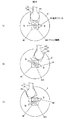
図3(a)〜図3(c)は、実施の形態に係るレバースイッチ装置のターン操作の検出について説明するためのマグネットと第1の磁気センサの位置に関する概略図である。図3(a)〜図3(c)は、第1の磁気センサ81を介してマグネット6を見た概略図となっている。なお図3(a)〜図3(c)に示す点線は、リンク45を示している。
(Operation)
FIG. 3A to FIG. 3C are schematic diagrams regarding the positions of the magnet and the first magnetic sensor for explaining detection of the turn operation of the lever switch device according to the embodiment. FIGS. 3A to 3C are schematic views of the
図3(a)は、ターン操作がなされていない場合を示し、図3(b)は、操作レバー3がTL方向に操作された場合を示し、図3(c)は、TR方向に操作された場合を示している。なお図3(a)〜図3(c)に示すブリッジ回路810は、各辺に磁気抵抗素子が配置されている。検出信号S1は、例えば、2つの磁気抵抗素子で作られたハーフブリッジ回路の中点電位の差分を取った差分電位として出力される。またブリッジ回路810は、一例として、図3(a)〜図3(c)の図面において左側と右側で2つのハーフブリッジ回路が形成されているものとする。
3A shows a case where the turn operation is not performed, FIG. 3B shows a case where the
操作レバー3がターン操作されない中立位置では、図3(a)に示すように、第1の磁気センサ81のブリッジ回路810に作用する磁気ベクトル65は、各磁気抵抗素子に対して実質的に45°となって各磁気抵抗素子の抵抗値が等しくなる。そのため、ブリッジ回路810の差分電位は、実質的にゼロとなり、第1の磁気センサ81がこの差分電位に応じた検出信号S1を出力する。制御部10は、当該検出信号S1としきい値情報100とに基づいてターン操作側の操作位置を中立位置と判定し、判定した結果をディマ操作及びパッシング操作の操作位置と合わせて操作信号S3として出力する。
In the neutral position where the
操作レバー3がTL方向に操作されると、操作レバー3は、第1の軸L1周りに回転する。レバーホルダ4は、操作レバー3と一体となって回転し、リンク45と連結されたマグネットホルダ7が第4の軸L4周りに、操作レバー3と同方向に回転する。
When the operating
マグネット6は、図3(b)の紙面において反時計回り、つまり左方向に回転する。このマグネット6の回転により、第1の磁気センサ81に作用する磁気ベクトル65が中立位置から反時計回りに回転する。第1の磁気センサ81は、図3(b)に示すように、磁気ベクトル65がブリッジ回路810に対して右肩上がりとなるように傾いているので、この傾きに応じた検出信号S1を制御部10に出力する。制御部10は、取得した検出信号S1としきい値情報100とに基づいて操作レバー3の操作位置をTL操作位置と判定し、判定した結果をディマ操作及びパッシング操作の操作位置と合わせて操作信号S3として出力する。
The
操作レバー3がTR方向に操作されると、操作レバー3は、第1の軸L1周りに回転する。レバーホルダ4は、操作レバー3と一体となって回転し、リンク45と連結されたマグネットホルダ7が第4の軸L4周りに、操作レバー3と同方向に回転する。
When the operating
マグネット6は、図3(c)の紙面において時計回り、つまり右方向に回転する。このマグネット6の回転により、第1の磁気センサ81に作用する磁気ベクトル65が中立位置から時計回りに回転する。第1の磁気センサ81は、図3(c)に示すように、磁気ベクトル65がブリッジ回路810に対して右肩下がりとなるように傾いているので、この傾きに応じた検出信号S1を制御部10に出力する。制御部10は、取得した検出信号S1としきい値情報100とに基づいて操作レバー3の操作位置をTR操作位置と判定し、判定した結果をディマ操作及びパッシング操作の操作位置と合わせて操作信号S3として出力する。
The
・ディマ操作及びパッシング操作について
図4(a)〜図4(c)は、実施の形態に係るレバースイッチ装置のディマ操作及びパッシング操作の検出について説明するためのマグネットと第2の磁気センサの位置に関する概略図である。図4(a)〜図4(c)は、第2の磁気センサ82を介してマグネット6を見た概略図となっている。
Dimmer Operation and Passing Operation FIGS. 4A to 4C show the positions of the magnet and the second magnetic sensor for explaining the detection of the dimmer operation and the passing operation of the lever switch device according to the embodiment. FIG. 4A to 4C are schematic views of the
図4(a)は、ディマ操作及びパッシング操作がなされていない場合を示し、図4(b)は、操作レバー3がD方向に操作された場合(ディマ操作)を示し、図3(c)は、P方向に操作された場合(パッシング操作)を示している。なお図4(a)〜図4(c)に示すブリッジ回路820は、各辺に磁気抵抗素子が配置されている。検出信号S2は、例えば、2つの磁気抵抗素子で作られたハーフブリッジ回路の出力電位の差分を取った差分電位として出力される。またブリッジ回路820は、一例として、図4(a)〜図4(c)の図面において左側と右側で2つのハーフブリッジ回路が形成されているものとする。
4A shows a case where the dimmer operation and the passing operation are not performed, and FIG. 4B shows a case where the
操作レバー3がディマ操作及びパッシング操作されない中立位置では、図4(a)に示すように、第2の磁気センサ82のブリッジ回路820に作用する磁気ベクトル66は、各磁気抵抗素子に対して実質的に45°となって各磁気抵抗素子の抵抗値が等しくなる。そのため、ブリッジ回路820の差分電位は、実質的にゼロとなり、第2の磁気センサ82がこの差分電位に応じた検出信号S2を出力する。制御部10は、当該検出信号S2としきい値情報100とに基づいてディマ操作及びパッシング操作側の操作位置を中立位置と判定し、判定した結果をターン操作の操作位置と合わせて操作信号S3として出力する。
In the neutral position where the
操作レバー3がD方向に操作されると、操作レバー3は、第2の軸L2周りに回転する。この回転によって操作レバー3の先端部32が上方向に移動し、突起33が変換部5のガイド部55の上側を押し上げる。この突起33による押し上げによって、変換部5が図2(b)の矢印D方向に、ガイド部55及び変換部5の突起56が挿入されたガイド部47にガイドされながら直線的に移動する。
When the operating
変換部5の矢印D方向の移動により、アーム51の球状端部52がマグネット6の溝部60を右方向に押す。マグネット6は、図4(b)に示すように、球状端部52からの右方向の力を受けて、第3の軸L3周りを時計回りに、マグネットホルダ7に対して回転する。このマグネット6の回転により、第2の磁気センサ82に作用する磁気ベクトル66が中立位置から時計回りに回転する。第2の磁気センサ82は、図4(b)に示すように、磁気ベクトル66がブリッジ回路820に対して右肩下がりとなるように傾いているので、この傾きに応じた検出信号S2を制御部10に出力する。制御部10は、取得した検出信号S2としきい値情報100とに基づいて操作レバー3の操作位置をディマ操作位置と判定し、判定した結果をターン操作の操作位置と合わせて操作信号S3として出力する。
The
操作レバー3がP方向に操作されると、操作レバー3は、第2の軸L2周りに回転する。この回転によって操作レバー3の先端部32が下方向に移動し、突起33が変換部5のガイド部55の下側を押し下げる。この突起33による押し下げによって、変換部5が図2(b)の矢印P方向に、ガイド部55及びガイド部47にガイドされながら直線的に移動する。
When the operating
変換部5の矢印P方向の移動により、球状端部52が溝部60を左方向に押す。マグネット6は、図4(c)に示すように、球状端部52からの左方向の力を受けて、第3の軸L3周りを反時計回りに、マグネットホルダ7に対して回転する。このマグネット6の回転により、第2の磁気センサ82に作用する磁気ベクトル66が中立位置から反時計回りに回転する。第2の磁気センサ82は、図4(c)に示すように、磁気ベクトル66がブリッジ回路820に対して右肩上がりとなるように傾いているので、この傾きに応じた検出信号S2を制御部10に出力する。制御部10は、取得した検出信号S2としきい値情報100とに基づいて操作レバー3の操作位置をパッシング操作位置と判定し、判定した結果をターン操作の操作位置と合わせて操作信号S3として出力する。
Due to the movement of the
上述のように、ターン操作の検出と、ディマ操作及びパッシング操作の検出は、独立に行われる。従ってレバースイッチ装置1は、ディマ操作が行われた状態でのターン操作やターン操作中のパッシング操作などを検出することができる。 As described above, the detection of the turn operation and the detection of the dimmer operation and the passing operation are performed independently. Therefore, the lever switch device 1 can detect a turn operation in a state where a dimmer operation is performed, a passing operation during the turn operation, and the like.
(実施の形態の効果)
本実施の形態に係るレバースイッチ装置1は、製造コストを抑制すると共に小型化することができる。具体的には、レバースイッチ装置1は、1つのマグネット6の交差する第3の軸L3及び第4の軸L4周りの回転を検出することによって操作レバーの第1の軸L1及び第2の軸L2周りの操作を検出することができる。従ってレバースイッチ装置1は、操作レバーの2つの軸周りの操作を検出するために2つの磁石が必要な場合と比べて、製造コストが抑制され、さらに2つの磁石を設置する必要がないので、小型化することができる。
(Effect of embodiment)
The lever switch device 1 according to the present embodiment can be reduced in size while reducing the manufacturing cost. Specifically, the lever switch device 1 detects the rotation around the third axis L 3 and the fourth axis L 4 where one
レバースイッチ装置1は、1つのマグネット6の回転によって操作レバー3の2軸の操作位置を検出することができるので、移動接点と固定接点との接点の切り替わりによって2軸の操作位置を検出する有接点の場合と比べて、検出範囲が小さくなって小型化することができる。
Since the lever switch device 1 can detect the two-axis operation position of the
レバースイッチ装置1は、2つの磁石を配置する場合と比べて、部品点数が少なくなるので、累積公差が小さくなると共に寸法のばらつきによる検出精度の低下を抑制することができ、操作位置の検出精度が向上する。 Since the lever switch device 1 has a smaller number of parts compared to the case where two magnets are arranged, the accumulated tolerance is reduced and a decrease in detection accuracy due to variation in dimensions can be suppressed, and the detection accuracy of the operation position can be suppressed. Will improve.
以上、本発明のいくつかの実施の形態を説明したが、これらの実施の形態は、一例に過ぎず、特許請求の範囲に係る発明を限定するものではない。これら新規な実施の形態は、その他の様々な形態で実施されることが可能であり、本発明の要旨を逸脱しない範囲で、種々の省略、置き換え、変更などを行うことができる。また、これら実施の形態の中で説明した特徴の組合せの全てが発明の課題を解決するための手段に必須であるとは限らない。さらに、これら実施の形態は、発明の範囲及び要旨に含まれるとともに、特許請求の範囲に記載された発明とその均等の範囲に含まれる。 As mentioned above, although some embodiment of this invention was described, these embodiment is only an example and does not limit the invention which concerns on a claim. These novel embodiments can be implemented in various other forms, and various omissions, replacements, changes, and the like can be made without departing from the scope of the present invention. In addition, not all the combinations of features described in these embodiments are essential to the means for solving the problems of the invention. Furthermore, these embodiments are included in the scope and gist of the invention, and are included in the invention described in the claims and the equivalents thereof.
1…レバースイッチ装置、2…筐体、3…操作レバー、4…レバーホルダ、5…変換部、6…マグネット、7…マグネットホルダ、9…車両、10…制御部、21…上部筐体、22…下部筐体、23…側面、30…挿入部、30a…側面、30b…側面、31…軸部、32…先端部、33…突起、40…貫通孔、41…軸部、42…円弧部、43…軸孔、44…突出部、45…リンク、46…開口、47…ガイド部、50…凹部、50a…側面、50b…側面、50c…底部、51…アーム、52…球状端部、55…ガイド部、56…突起、60…溝部、61…軸部、65…磁気ベクトル、66…磁気ベクトル、70…挿入凹部、71…保持部、72…軸孔、75…リングガイド部、81…第1の磁気センサ、82…第2の磁気センサ、90…ステアリング、91…コラムカバー、100…しきい値情報、210…開口、211…軸穴、220…リング溝部、221…円弧溝、810…ブリッジ回路、820…ブリッジ回路
DESCRIPTION OF SYMBOLS 1 ... Lever switch apparatus, 2 ... Housing | casing, 3 ... Operation lever, 4 ... Lever holder, 5 ... Conversion part, 6 ... Magnet, 7 ... Magnet holder, 9 ... Vehicle, 10 ... Control part, 21 ... Upper housing | casing, DESCRIPTION OF
Claims (5)
第1のリンクを有し、前記操作レバーと一体となって前記第1の軸周りに回転すると共に前記操作レバーの前記第2の軸周りの回転が可能となるように前記操作レバーを保持する第1のホルダと、
第2のリンクを有し、前記第1のホルダに取り付けられ、前記操作レバーの前記第2の軸周りの回転を前記第2のリンクの直線的な移動に変換する変換部と、
周囲に磁場を生成すると共に前記第2のリンクが挿入される被挿入部を有し、前記被挿入部に挿入された前記第2のリンクの直線的な移動によって第3の軸周りに回転する磁場生成部と、
前記第3の軸周りの回転が可能となるように前記磁場生成部を保持し、前記第1のホルダの前記第1のリンクと連結されて前記操作レバーの前記第1の軸周りの回転によって前記第3の軸と交差する第4の軸周りに前記磁場生成部と共に回転する第2のホルダと、
前記磁場生成部の前記第4の軸周りの回転の検出を介して前記操作レバーの前記第1の軸周りの回転を検出する第1の磁気センサと、
前記磁場生成部の前記第3の軸周りの回転の検出を介して前記操作レバーの前記第2の軸周りの回転を検出する第2の磁気センサと、
を備えたレバースイッチ装置。 An operating lever that rotates about a first axis and a second axis that intersect,
A first link is provided, and rotates around the first axis integrally with the operation lever and holds the operation lever so that the operation lever can rotate around the second axis. A first holder;
A conversion unit that has a second link, is attached to the first holder, and converts rotation of the operation lever around the second axis into linear movement of the second link;
It has a portion to be inserted into which the second link is inserted while generating a magnetic field around it, and rotates around a third axis by a linear movement of the second link inserted into the portion to be inserted A magnetic field generator,
The magnetic field generation unit is held so as to be able to rotate around the third axis, and is connected to the first link of the first holder, and the operation lever is rotated around the first axis. A second holder that rotates with the magnetic field generator about a fourth axis that intersects the third axis;
A first magnetic sensor that detects rotation of the operating lever around the first axis through detection of rotation of the magnetic field generation unit around the fourth axis;
A second magnetic sensor that detects rotation of the operating lever around the second axis through detection of rotation of the magnetic field generation unit around the third axis;
Lever switch device with
請求項1に記載のレバースイッチ装置。 The first axis and the fourth axis are substantially parallel;
The lever switch device according to claim 1.
前記変換部は、前記開口を介して前記第2のリンクを前記第1のホルダの外に突出させ、前記磁場生成部の前記被挿入部に挿入する、
請求項1又は2に記載のレバースイッチ装置。 The first holder has an opening on the magnetic field generation unit side,
The conversion unit causes the second link to protrude out of the first holder through the opening, and is inserted into the insertion portion of the magnetic field generation unit.
The lever switch device according to claim 1 or 2.
前記被挿入部は、側面に溝として形成される、
請求項1乃至3のいずれか1項に記載のレバースイッチ装置。 The magnetic field generator has a cylindrical shape,
The inserted portion is formed as a groove on a side surface,
The lever switch device according to any one of claims 1 to 3.
請求項1乃至4のいずれか1項に記載のレバースイッチ装置。 The first shaft and the second shaft of the operating lever based on a first detection signal output from the first magnetic sensor and a second detection signal output from the second magnetic sensor Provided with a determination unit for determining four operation positions based on the surrounding rotation;
The lever switch device according to any one of claims 1 to 4.
Priority Applications (1)
| Application Number | Priority Date | Filing Date | Title |
|---|---|---|---|
| JP2015133588A JP2017016920A (en) | 2015-07-02 | 2015-07-02 | Lever switch apparatus |
Applications Claiming Priority (1)
| Application Number | Priority Date | Filing Date | Title |
|---|---|---|---|
| JP2015133588A JP2017016920A (en) | 2015-07-02 | 2015-07-02 | Lever switch apparatus |
Publications (1)
| Publication Number | Publication Date |
|---|---|
| JP2017016920A true JP2017016920A (en) | 2017-01-19 |
Family
ID=57829157
Family Applications (1)
| Application Number | Title | Priority Date | Filing Date |
|---|---|---|---|
| JP2015133588A Pending JP2017016920A (en) | 2015-07-02 | 2015-07-02 | Lever switch apparatus |
Country Status (1)
| Country | Link |
|---|---|
| JP (1) | JP2017016920A (en) |
Cited By (2)
| Publication number | Priority date | Publication date | Assignee | Title |
|---|---|---|---|---|
| WO2018215157A1 (en) * | 2017-05-22 | 2018-11-29 | Valeo Schalter Und Sensoren Gmbh | Switch with deflection lever and large switching path |
| WO2020193132A1 (en) * | 2019-03-22 | 2020-10-01 | Valeo Schalter Und Sensoren Gmbh | Steering column switch for a vehicle |
-
2015
- 2015-07-02 JP JP2015133588A patent/JP2017016920A/en active Pending
Cited By (5)
| Publication number | Priority date | Publication date | Assignee | Title |
|---|---|---|---|---|
| WO2018215157A1 (en) * | 2017-05-22 | 2018-11-29 | Valeo Schalter Und Sensoren Gmbh | Switch with deflection lever and large switching path |
| CN110678358A (en) * | 2017-05-22 | 2020-01-10 | 法雷奥开关和传感器有限责任公司 | Switch with deflection lever and large switching path |
| US11433802B2 (en) | 2017-05-22 | 2022-09-06 | Valeo Schalter Und Sensoren Gmbh | Switch with reversing lever and large switching path |
| WO2020193132A1 (en) * | 2019-03-22 | 2020-10-01 | Valeo Schalter Und Sensoren Gmbh | Steering column switch for a vehicle |
| CN113874252A (en) * | 2019-03-22 | 2021-12-31 | 法雷奥开关和传感器有限责任公司 | Steering column switch for vehicle |
Similar Documents
| Publication | Publication Date | Title |
|---|---|---|
| JP4629591B2 (en) | Shift device | |
| JP2017016920A (en) | Lever switch apparatus | |
| WO2010026947A1 (en) | Shift device | |
| US10176944B2 (en) | Rotational movement detection device | |
| JP6420687B2 (en) | Position detection device | |
| JP4954808B2 (en) | Non-contact switch | |
| JP6853900B2 (en) | Shift device | |
| JP6230069B2 (en) | Lever switch device | |
| JP2009140659A (en) | Stoke switch device | |
| US10539430B2 (en) | Position detecting device | |
| JP2017037740A (en) | Lever switch device | |
| JP4885086B2 (en) | Non-contact switch | |
| CN111587355B (en) | Input device | |
| WO2016002450A1 (en) | Rotational movement detection device | |
| WO2017026179A1 (en) | Magnetic detector | |
| JP2016012465A (en) | Lever switch device | |
| CN111565959A (en) | Gear shift device | |
| US20210396550A1 (en) | Position detection device | |
| WO2016002451A1 (en) | Rotation movement detection device | |
| JP2009123366A (en) | Stoke switch device | |
| US11803205B2 (en) | Lever operation device | |
| JP7352795B2 (en) | Input device and moving object | |
| JP2011163783A (en) | Operating position detector | |
| JP2005195471A (en) | Rotation angle detecting device | |
| JP2015109151A (en) | Lever switch device |