JP2017016787A - Current collector for secondary battery - Google Patents
Current collector for secondary battery Download PDFInfo
- Publication number
- JP2017016787A JP2017016787A JP2015130180A JP2015130180A JP2017016787A JP 2017016787 A JP2017016787 A JP 2017016787A JP 2015130180 A JP2015130180 A JP 2015130180A JP 2015130180 A JP2015130180 A JP 2015130180A JP 2017016787 A JP2017016787 A JP 2017016787A
- Authority
- JP
- Japan
- Prior art keywords
- current collector
- resin film
- positive electrode
- metal foil
- nail
- Prior art date
- Legal status (The legal status is an assumption and is not a legal conclusion. Google has not performed a legal analysis and makes no representation as to the accuracy of the status listed.)
- Pending
Links
Images


Classifications
-
- Y—GENERAL TAGGING OF NEW TECHNOLOGICAL DEVELOPMENTS; GENERAL TAGGING OF CROSS-SECTIONAL TECHNOLOGIES SPANNING OVER SEVERAL SECTIONS OF THE IPC; TECHNICAL SUBJECTS COVERED BY FORMER USPC CROSS-REFERENCE ART COLLECTIONS [XRACs] AND DIGESTS
- Y02—TECHNOLOGIES OR APPLICATIONS FOR MITIGATION OR ADAPTATION AGAINST CLIMATE CHANGE
- Y02E—REDUCTION OF GREENHOUSE GAS [GHG] EMISSIONS, RELATED TO ENERGY GENERATION, TRANSMISSION OR DISTRIBUTION
- Y02E60/00—Enabling technologies; Technologies with a potential or indirect contribution to GHG emissions mitigation
- Y02E60/10—Energy storage using batteries
Abstract
Description
本発明は、二次電池用の集電体に関する。 The present invention relates to a current collector for a secondary battery.
リチウムイオン電池のような二次電池では、金属の釘が電池に突き刺さったり、金属材料が電池内部で析出したりすると、これら金属の異物により正極の集電体と負極の集電体とが短絡される内部短絡が起こり得る。内部短絡が起こると、正極の集電体から負極の集電体へ向かって金属異物を介して短絡電流が流れる。このとき、短絡電流は金属異物に集中して流れるため、金属異物がジュール熱により発熱するおそれがある。 In a secondary battery such as a lithium ion battery, when a metal nail pierces the battery or a metal material is deposited inside the battery, the positive electrode current collector and the negative electrode current collector are short-circuited by foreign matters of the metal. Internal short circuit can occur. When an internal short circuit occurs, a short circuit current flows from the positive electrode current collector to the negative electrode current collector through the metal foreign object. At this time, since the short-circuit current concentrates on the metal foreign object, the metal foreign object may generate heat due to Joule heat.
したがって、電池内部の安全機構として、内部短絡が発生した場合でも、正極の集電体と負極の集電体との間の絶縁性を回復し、内部短絡を解消する機構が重要である。 Therefore, as a safety mechanism inside the battery, even when an internal short circuit occurs, a mechanism that recovers the insulation between the positive electrode current collector and the negative electrode current collector and eliminates the internal short circuit is important.
内部短絡に対する安全機構として、例えば特許文献1には、二次電池用の集電体として、プラスチックフィルムに金属薄膜を成膜したものを用いる技術が開示されている。また、特許文献2には、二次電池用の集電体として、樹脂フィルムに金属層を形成したものを用いる技術が開示されている。これらの集電体を用いると、内部短絡が発生したときには内部短絡に伴う発熱でプラスチックフィルム又は樹脂フィルムが溶融し金属薄膜又は金属層が飛散して、短絡電流が遮断され、それにより電池温度の急激な上昇が抑制できる、と記載されている。
As a safety mechanism against an internal short circuit, for example,
特許文献1の技術を車両用二次電池のような高出力の二次電池に適用する場合、集電体でのジュール損失の低減のために、薄く高抵抗な金属薄膜ではなく、厚く低抵抗な金属箔を集電体として用いる必要がある。しかし、集電体を金属箔に変更した場合、金属箔自体の強度が大きいため、内部短絡に伴う発熱によりプラスチックフィルムが溶融しても、金属箔が飛散することはなく、それゆえ短絡電流が遮断されない。内部短絡が発生したときに、集電体として金属箔を用いていても、短絡電流を遮断可能な技術が望まれる。
When the technique of
本発明によれば、二次電池用の集電体であって、金属箔と、前記金属箔の一方の面に接合された樹脂フィルムと、を備え、前記樹脂フィルムは、融点が200℃以上であり、収縮開始温度が100℃以上、前記溶融温度未満である、二次電池の電極用の集電体、が提供される。 According to the present invention, a current collector for a secondary battery comprising a metal foil and a resin film bonded to one surface of the metal foil, the resin film having a melting point of 200 ° C. or higher. And a current collector for an electrode of a secondary battery having a shrinkage start temperature of 100 ° C. or higher and lower than the melting temperature.
本発明の集電体によれば、内部短絡が発生したときに、集電体として金属箔を用いても、短絡電流を遮断することができる。 According to the current collector of the present invention, when an internal short circuit occurs, the short circuit current can be interrupted even if a metal foil is used as the current collector.
本発明によれば、二次電池用の集電体であって、金属箔と、金属箔の一方の面に接合された樹脂フィルムと、を備え、樹脂フィルムは、融点が200℃以上であり、収縮開始温度が100℃以上、融点未満である、二次電池用の集電体、が提供される。 According to the present invention, a current collector for a secondary battery comprising a metal foil and a resin film bonded to one surface of the metal foil, the resin film having a melting point of 200 ° C. or higher. A current collector for a secondary battery having a shrinkage start temperature of 100 ° C. or higher and lower than the melting point is provided.
上記の集電体は二次電池の正極及び/又は負極の集電体として利用することができる。その集電体を利用した二次電池では、金属異物が正極の集電体と負極の集電体とを短絡して内部短絡が発生したとき、短絡電流の流れる金属異物及びその周辺の温度が高くなるため、金属異物の周辺の樹脂フィルムの温度も高くなる。そのため、金属異物の周囲の樹脂フィルムが金属異物から離れるように熱収縮することになる。ここで、金属箔は樹脂フィルムの一方の面に接合されているので、樹脂フィルムの収縮に追随して、金属箔も金属異物から離れることになる。すなわち、樹脂フィルムは熱収縮力により金属箔を金属異物から引き離す。その結果、金属箔が金属異物と接触しなくなるため、短絡電流を遮断することができる。それにより、内部短絡が発生しても、早期に内部短絡を解消でき、二次電池の安全性を向上させることができる。 The current collector can be used as a current collector for a positive electrode and / or a negative electrode of a secondary battery. In the secondary battery using the current collector, when the metal foreign object short-circuits the positive electrode current collector and the negative electrode current collector to cause an internal short circuit, the metal foreign object through which the short-circuit current flows and the temperature around it are Since it becomes high, the temperature of the resin film around a metal foreign material also becomes high. Therefore, the resin film around the metal foreign object is thermally contracted so as to be separated from the metal foreign object. Here, since the metal foil is bonded to one surface of the resin film, the metal foil also moves away from the metal foreign object following the contraction of the resin film. That is, the resin film pulls the metal foil away from the metal foreign matter by the heat shrinkage force. As a result, since the metal foil does not come into contact with the metal foreign object, the short circuit current can be interrupted. Thereby, even if an internal short circuit occurs, the internal short circuit can be eliminated at an early stage, and the safety of the secondary battery can be improved.
ただし、電池の製造時や電池の作動時に樹脂フィルムが収縮して金属箔に悪影響を与えることがないように、製造時の処理温度や作動時の電池温度に対応する温度域、すなわち100℃未満ではほとんど収縮しない樹脂フィルムを用いる。一方、内部短絡が発生した時には樹脂フィルムが金属箔を金属異物から引き離せるように、内部短絡が発生して発熱量が増大する温度域、すなわち100℃以上、樹脂フィルムの融点未満で、収縮が開始される樹脂フィルムを用いる。言い換えると、収縮開始温度が100℃以上、融点未満である樹脂フィルムを用いる。このとき樹脂フィルムは収縮開始温度から融点まで収縮挙動が継続する。 However, the temperature range corresponding to the processing temperature at the time of manufacture and the battery temperature at the time of operation, that is, less than 100 ° C., so that the resin film does not shrink and adversely affect the metal foil at the time of battery manufacture or operation. Then, a resin film that hardly shrinks is used. On the other hand, when an internal short circuit occurs, the resin film shrinks at a temperature range where the internal short circuit occurs and the amount of heat generation increases, that is, at 100 ° C. or higher and below the melting point of the resin film, so that the metal foil can be separated from the metal foreign object. Use a resin film that starts. In other words, a resin film having a shrinkage start temperature of 100 ° C. or higher and lower than the melting point is used. At this time, the shrinkage behavior of the resin film continues from the shrinkage start temperature to the melting point.
ここで、上側の境界を融点未満にするのは、融点においては樹脂フィルムが溶融して、金属箔から剥離してしまい、金属箔を金属異物から引き離せられず、内部短絡を解消できないからである。また、樹脂フィルムの融点を200℃以上にするのは、融点が低過ぎると樹脂フィルムが十分に収縮するまえに、樹脂フィルムが溶融してしまい、内部短絡の解消が十分にできなくなるからである。 Here, the upper boundary is made lower than the melting point because the resin film melts and peels off from the metal foil at the melting point, and the metal foil cannot be separated from the metal foreign matter, and the internal short circuit cannot be eliminated. is there. The reason why the melting point of the resin film is 200 ° C. or higher is that if the melting point is too low, the resin film melts before the resin film sufficiently contracts, and the internal short circuit cannot be sufficiently eliminated. .
樹脂フィルムの材料としては、融点が200℃以上であり、収縮開始温度が100℃以上、融点未満である樹脂であれば特に制限はない。樹脂フィルムの材料としては、例えばポリエチレンテレフテラート(PET)、ポリブチレンテレフタレート(PBT)、ポリエチレンナフタレート(PEN)又はPET、PBT若しくはPENを主成分(最も多い成分)として含む樹脂が例示される。また、樹脂フィルムの厚みは、特に制限はないが、下限としては5μm以上が好ましく、10μm以上がより好ましい。薄過ぎると収縮のとき金属箔を引っ張る力が弱くなるためである。上限としては20μm以下が好ましく、10μm以下がより好ましい。厚過ぎるとエネルギー密度が低くなるためである。 The material of the resin film is not particularly limited as long as the resin has a melting point of 200 ° C. or higher, a shrinkage start temperature of 100 ° C. or higher and lower than the melting point. Examples of the material of the resin film include polyethylene terephthalate (PET), polybutylene terephthalate (PBT), polyethylene naphthalate (PEN), or a resin containing PET, PBT, or PEN as a main component (most component). . The thickness of the resin film is not particularly limited, but the lower limit is preferably 5 μm or more, and more preferably 10 μm or more. This is because if the film is too thin, the force for pulling the metal foil is weakened during shrinkage. As an upper limit, 20 micrometers or less are preferable and 10 micrometers or less are more preferable. This is because if it is too thick, the energy density is lowered.
金属箔の材料としては、二次電池の集電体として使用可能な材料であれば特に制限はない。例えば二次電池がリチウムイオン電池の場合、集電体を正極に用いるときには、金属箔の材料としてアルミニウム、ニッケル又はステンレスが例示される。また、集電体を負極に用いるときには、金属箔の材料として銅又は銅を含む合金が例示される。金属箔の厚みは、特に制限はないが、下限としては4μm以上が好ましく、6μm以上がより好ましい。薄過ぎると抵抗が高くなるためである。上限としては20μmが好ましく、10μm以下がより好ましい。厚過ぎると樹脂フィルムの収縮に追随して金属異物から離れることが困難になるためである。 The material of the metal foil is not particularly limited as long as it is a material that can be used as a current collector for a secondary battery. For example, when the secondary battery is a lithium ion battery, when the current collector is used for the positive electrode, examples of the metal foil material include aluminum, nickel, and stainless steel. Further, when the current collector is used for the negative electrode, copper or an alloy containing copper is exemplified as the material of the metal foil. Although there is no restriction | limiting in particular in the thickness of metal foil, 4 micrometers or more are preferable as a minimum, and 6 micrometers or more are more preferable. This is because the resistance is increased if it is too thin. As an upper limit, 20 micrometers is preferable and 10 micrometers or less are more preferable. If it is too thick, it is difficult to follow the shrinkage of the resin film and leave the metal foreign object.
樹脂フィルムと金属箔とは接着剤で接着される。接着剤の材料としては、樹脂フィルムと金属箔とを接着でき、かつ、樹脂フィルムの融点(例示:200℃)まで樹脂フィルムと金属箔との接合を維持できる材料でれば特に制限はない。 The resin film and the metal foil are bonded with an adhesive. The material of the adhesive is not particularly limited as long as it is a material that can bond the resin film and the metal foil and can maintain the bonding between the resin film and the metal foil up to the melting point of the resin film (example: 200 ° C.).
樹脂フィルムの収縮は、金属異物とその周囲の金属箔との間に隙間ができる程度、すなわち金属異物と金属箔とが互いに接触しなくなる程度に収縮することが好ましい。そのような収縮を実現できる収縮率としては、金属異物と金属箔との接触の形態にも依るが、例えば収縮率1%以上が好ましく、10%以上がより好ましい。 The resin film is preferably contracted to such an extent that a gap is formed between the metal foreign object and the surrounding metal foil, that is, the metal foreign object and the metal foil are not in contact with each other. The shrinkage rate that can realize such shrinkage depends on the form of contact between the metal foreign object and the metal foil, but for example, the shrinkage rate is preferably 1% or more, and more preferably 10% or more.
次に、上記の集電体を利用した二次電池について、図面を参照して説明する。ここで、二次電池としては特に限定されるものではないが、以下では、二次電池としてリチウムイオン電池を例に説明する。ここでは、上記の集電体を正極集電体として用いる。 Next, a secondary battery using the current collector will be described with reference to the drawings. Here, although it does not specifically limit as a secondary battery, Below, a lithium ion battery is demonstrated to an example as a secondary battery. Here, the current collector is used as a positive electrode current collector.
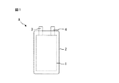
まず、上記の集電体を利用したリチウムイオン電池の構成について説明する。図1はリチウムイオン電池の構成例を示す正面図である。リチウムイオン電池Aは、充放電可能な二次電池であり、二次電池の本体である電池素子1と、電池素子1の正極側の端子である正極タブ3と、電池素子1の負極側の端子である負極タブ4と、電池素子1を格納する容器2とを備えている。容器2としては、金属容器やラミネートフィルムが例示される。金属容器としては例えばステンレス容器が挙げられる。ラミネートフィルムとしては例えばアルミラミネートフィルムが挙げられる。図1の例では容器2はステンレス容器であり、正極タブ3及び負極タブ4の一部は外部へ延在している。
First, a configuration of a lithium ion battery using the above current collector will be described. FIG. 1 is a front view showing a configuration example of a lithium ion battery. The lithium ion battery A is a rechargeable secondary battery. The
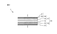
図2は、電池素子1の構成例を示す部分断面図である。電池素子1は、複数の単セル10が積層された構成を有している。単セル10は、充放電可能な単体の電池であり、正極層11と、負極層12と、正極層11と負極層12との間に配置されたセパレータ層13と、正極層11、負極層12及びセパレータ層13を浸漬する電解液(図示せず)とを備えている。正極層11は、正極活物質を含む正極活物質層14と、正極活物質層14の集電を行う正極集電体16とを備えている。正極集電体16の延長部分(図示せず)は、正極タブ3に接続される。正極集電体16は、金属箔22と、金属箔22の一方の面に接合された樹脂フィルム21とを備えている。樹脂フィルム21は、融点が200℃以上であり、収縮開始温度が100℃以上、融点未満である。負極層12は、負極活物質を含む負極活物質層15と、負極活物質層15の集電を行う負極集電体17とを備えている。負極集電体17の延長部分(図示せず)は、負極タブ4接続される。隣り合う単セル10は、例えば別のセパレータ層を挟んで積層される。なお、図1および図2の例では、リチウムイオン電池Aは積層型であるが、本実施の形態はその例に限定されるものではなく、リチウムイオン電池Aは巻回型であってもよい。なお、電解質として、電解液ではなく、電解液を含んだポリマーゲル電解質を用いてもよく、その場合、ポリマーゲル電解質は正極層11と負極層12との間に介在する。
FIG. 2 is a partial cross-sectional view showing a configuration example of the
次に、上記の集電体を利用したリチウムイオン電池に釘が刺さったときの作用について説明する。図3及び図4は、金属異物として釘30が刺さったときの電池素子1の状態を示す部分断面図である。釘30が単セル10の一方の側から他方の側まで、すなわち正極層11から負極層12まで貫通すると、正極集電体16と負極集電体17とが電気の良導体である釘30を介して接続されて、内部短絡が発生する。すなわち正極集電体16から負極集電体17へ向かって短絡電流Iが釘30内に集中的に流れる。このとき、短絡電流Iの流れる釘30及びその周辺の温度がジュール熱で高くなり、釘30の周辺の樹脂フィルム21の温度が高くなる。その結果、図4に示すように、釘30の周辺から離れるように、釘30の周囲の樹脂フィルム21が熱収縮する。ここで、金属箔22は樹脂フィルム21に接合されているので、樹脂フィルム21の収縮に追随して、金属箔22も釘30の周辺から離れる。その結果、金属箔22と釘30との間に隙間25が形成され、金属箔22と釘30が接触しなくなるため、短絡電流Iを遮断することができる。
Next, an operation when a nail is pierced into the lithium ion battery using the current collector will be described. 3 and 4 are partial cross-sectional views showing the state of the
なお、図2〜図4に示す例では電池素子1の正極集電体16が金属箔22と樹脂フィルム21とから構成されている。しかし、本実施の形態はこの例に限定されるものではなく、正極集電体16の代わりに、又は、正極集電体16と共に、負極集電体17が金属箔とその金属箔の一方の面に接合された樹脂フィルムとから構成されていてもよい。
In the example shown in FIGS. 2 to 4, the positive electrode
次に、上記の電池素子1の材料について説明する。
Next, the material of the
正極層11の正極活物質層14の材料としては、リチウムイオン電池の正極活物質として使用可能な従来知られた材料を用いることができ、例えばLiNi1/3Co1/3Mn1/3O2のような層状岩塩型化合物、LiMn2O4のようなスピネル型化合物、LiFePO4のようなオリビン型化合物が挙げられる。
As a material of the positive electrode
正極活物質層14は他の成分、例えば導電助剤及びバインダーを更に含んでもよい。導電助剤としてはVGCF(Vapor Grown Carbon Fiber)、カーボンブラックなどの炭素材が例示される。バインダーとしてはポリテトラフロオロエチレン、ポリブタジエンゴムなどが例示される。
The positive electrode
正極層11の正極集電体16の金属箔22の材料としては、リチウムイオン電池の正極集電体として使用可能な従来知られた材料であれば特に制限はなく、例えばアルミニウムが挙げられる。正極集電体16が接続される正極タブ3の材料としては金属箔22と同じ材料を用いることができる。
The material of the
正極集電体16の樹脂フィルム21の材料としては、融点が200℃以上であり、100℃以上、融点未満の温度域で収縮する樹脂であれば特に制限はなく、例えばポリエチレンテレフテラート(PET)が挙げられる。
The material of the
負極層12の負極活物質層15の材料としては、リチウムイオン電池の負極活物質として使用可能な従来知られた材料を用いることができ、例えばLiを含む金属や合金、天然又は人造黒鉛、ソフトカーボン、ハードカーボンなどの炭素材料が挙げられる。
As a material of the negative electrode
負極活物質層15は他の成分、例えば導電助剤及びバインダーを更に含んでもよい。導電助剤及びバインダーについては上述の正極活物質層14の場合と同じ材料を用いることができる。
The negative electrode
負極層12の負極集電体17の材料としては、リチウムイオン電池の負極集電体として使用可能な従来知られた材料であれば特に制限はなく、例えば銅、銅を含む合金のような金属材料が挙げられる。負極集電体17の形状としては箔状、板状、メッシュ状等が例示される。負極集電体17が接続される負極タブ4の材料としては負極集電体17と同じ材料を用いることができる。
The material of the negative electrode
セパレータ層13の材料としては、絶縁性を有する多孔膜であれば特に制限はないが、ポリプロピレン(PP)、ポリエチレン(PE)のようなポリオレフィンの単層又は複数層の微多孔膜、または、それらと無機多孔膜との積層膜が例示される。セパレータ層13は、単層構造であっても良く、複層構造であっても良い。単セル10間に配置される別のセパレータ層の材料も同様の材料を用いることができる。
The material of the
電池素子1の電解液(図示せず)は、リチウム塩と溶剤とを含み、リチウムイオン電池の電解液として使用可能な従来知られた材料を用いることができる。リチウム塩としては、例えば六フッ化リン酸リチウム(LiPF6)、四フッ化リン酸リチウム(LiBF4)が挙げられ、溶剤としては、例えば環状エステル類(エチレンカーボネート(EC)など)、鎖状エステル類(ジメチルカーボネート(DMC)など)が挙げられる。また、溶剤は、イオン液体であってもよい。上記電解液を含んだポリマーゲル電解質を用いてもよい。
As the electrolytic solution (not shown) of the
なお、本実施の形態に係る電池素子1は、上述されたリチウムイオン電池ではなく、他の二次電池、例えば全固体電池であってもよい。その場合、電解質としては、電解液ではなく固体電解質を用いる。固体電解質の材料としては、全固体電池の電解質として使用可能な従来知られた材料であれば特に制限はなく、例えば結晶、非結晶又はガラスセラミックの硫化物や酸化物のような無機固体電解質が挙げられ、LiIを含むLi2S−P2S5などの硫化物系固体電解質やLi2O−B2O3−P2O5などの酸化物系固体電解質が例示される。また、正極活物質層及び負極活物質層には上記固体電解質が更に混合される。
Note that the
以下、本発明の実施例を示す。以下の実施例は単に説明するためのものであり、本発明を限定するものではない。 Examples of the present invention will be described below. The following examples are for illustrative purposes only and are not intended to limit the invention.
(1)評価用の単セルの作製
実施例及び比較例1、2の単セルを作製した。ただし電解液には浸漬していない。
(1) Production of single cell for evaluation Single cells of Examples and Comparative Examples 1 and 2 were produced. However, it is not immersed in the electrolyte.
実施例1の単セルは図2に示す単セル10の構成を有する。ただし、正極集電体16の樹脂フィルム21の材料としてはPETが用いられ、金属箔22の材料としては厚み6μmのアルミニウム箔が用いられた。樹脂フィルム21と金属箔22とは接着剤で接合された。この樹脂フィルム21(PET)は、融点が200℃以上あり、図5に示すように115℃にて1%の収縮率であり、すなわち収縮開始温度が100〜200℃であり、160℃にて15.7%の収縮率であった。
The single cell of Example 1 has the configuration of the
比較例1の単セルは図2に示す単セル10において正極集電体16の樹脂フィルム21を備えず金属箔22のみを備える構成を有する。ただし、金属箔22の材料としては厚み6μmのアルミニウム箔が用いられた。その他の材料は実施例と同じである。
The single cell of Comparative Example 1 has a configuration in which the
比較例2の単セルは図2に示す単セル10の構成を有する。ただし、正極集電体16の樹脂フィルム21の材料としてはポリプロピレン(PP)が用いられ、金属箔22の材料としては厚み6μmのアルミニウム箔が用いられた。樹脂フィルム21と金属箔22とは実施例1と同じ接着剤で接合された。この樹脂フィルム21(PP)は、融点が160℃であり、図5に示すように融点以下では収縮挙動はほとんど確認されず(<1%)、融点に達すると収縮挙動が見られた(図示せず)。その他の材料は実施例と同じである。
The single cell of Comparative Example 2 has the configuration of the
(2)単セルの評価
図6は釘刺し試験器を示す側面図である。釘刺し試験器40は、単セルCに釘を刺して内部短絡の状態を模擬的に試験する装置である。釘刺し試験器40は、円形の貫通孔46を中央に有し、単セルCを上下から挟持する二つの治具41と、二つの治具41の貫通孔46に挿入される釘42とを備えている。釘42の先端の内部には加熱ヒーター43が内蔵されており、釘42を加熱することができる。釘刺し試験器40は、更に、釘42と単セルCの正極集電体Eとの間の接触抵抗Rを計測する抵抗計44と、加熱ヒーター43の温度を計測する温度センサ45とを備えている。
(2) Evaluation of single cell FIG. 6 is a side view showing a nail penetration tester. The
釘刺し試験では、単セルCの正極集電体Eとして実施例、比較例1、2の単セルの正極集電体をそれぞれ評価した。すなわち、二つの治具41で単セルCを上下から挟持し、貫通孔46内に露出した単セルCを釘42で刺し、加熱ヒーター43で釘42を加熱することで釘42が貫通した単セルCを加熱する。加熱温度は室温〜約200℃である。これにより、釘が単セルに刺さり、単セルに内部短絡が発生して、ジュール熱により単セルが発熱する、という状態を模擬した。この状態で、釘42と単セルCの正極集電体Eとの間の接触抵抗Rを計測することにより、釘42と正極集電体Eとの接触度合い、すなわち内部短絡の度合いを評価した。
In the nail penetration test, each of the positive electrode current collectors of the single cells of Examples and Comparative Examples 1 and 2 was evaluated as the positive electrode current collector E of the single cell C. That is, the single cell C is sandwiched from above and below by the two
図7は釘42と正極集電体Eとの接触抵抗Rを示すグラフである。縦軸は抵抗計44で計測される接触抵抗Rを示し、横軸は温度センサ45で計測されるヒーター温度を示す。ヒーター温度は、釘42近傍の正極集電体Eの温度を概ね示し、すなわち内部短絡が発生したときの正極集電体Eの温度を概ね示している。
FIG. 7 is a graph showing the contact resistance R between the
図7に示すように、実施例では、約150℃以上においてヒーター温度の上昇と共に接触抵抗Rが大きく増加した。温度上昇により樹脂フィルムが収縮して(図5)釘42から離れると共に、アルミニウム箔を釘42から引き離したためである。
As shown in FIG. 7, in the example, the contact resistance R greatly increased as the heater temperature increased at about 150 ° C. or higher. This is because the resin film contracts due to the temperature rise (FIG. 5) and leaves the
一方、比較例1では、ヒーター温度の上昇によっても、接触抵抗Rはほとんど変化しなかった。温度上昇によってもアルミニウム箔が収縮せず釘42から離れなかったためである。
On the other hand, in Comparative Example 1, the contact resistance R hardly changed even when the heater temperature increased. This is because the aluminum foil did not shrink and did not leave the
また、比較例2では、ヒーター温度の上昇によっても、接触抵抗Rはほとんど変化しなかった。温度上昇により樹脂フィルムがほとんど収縮せずに(図5)溶融したため、樹脂フィルムはアルミニウム箔から剥離してしまい、アルミニウム箔を釘42から引き離せなかったためである。
In Comparative Example 2, the contact resistance R hardly changed even when the heater temperature increased. This is because the resin film melted with almost no shrinkage due to the temperature rise (FIG. 5), and the resin film was peeled off from the aluminum foil, and the aluminum foil could not be pulled away from the
本発明では、樹脂フィルムが収縮する力により、良好な電気伝導体である集電用の金属箔を釘から物理的に離して、金属箔と釘との間に急激な接触抵抗の上昇を発生させることができる。すなわち、金属箔と樹脂フィルムとを貼り合わせた集電体を用いることで、樹脂フィルムの収縮挙動により、集電体と釘のような金属異物との接触を解消することができる。それにより、内部短絡が発生しても、早期に内部短絡を解消でき、二次電池の安全性を向上させることができる。 In the present invention, due to the shrinking force of the resin film, the metal foil for current collection, which is a good electrical conductor, is physically separated from the nail, and a sudden increase in contact resistance occurs between the metal foil and the nail. Can be made. That is, by using a current collector obtained by bonding a metal foil and a resin film, contact between the current collector and a metal foreign object such as a nail can be eliminated by the shrinkage behavior of the resin film. Thereby, even if an internal short circuit occurs, the internal short circuit can be eliminated at an early stage, and the safety of the secondary battery can be improved.
A リチウムイオン電池
1 電池素子
2 容器
3 正極タブ
4 負極タブ
10 単セル
11 正極層
12 負極層
13 セパレータ層
14 正極活物質層
15 負極活物質層
16 正極集電体
17 負極集電体
18 正極タブ
21 樹脂フィルム
22 金属箔
30 釘
A
Claims (1)
金属箔と、
前記金属箔の一方の面に接合された樹脂フィルムと、
を備え、
前記樹脂フィルムは、
融点が200℃以上であり、
収縮開始温度が100℃以上、前記融点未満である、
二次電池用の集電体。 A current collector for a secondary battery,
Metal foil,
A resin film bonded to one surface of the metal foil;
With
The resin film is
The melting point is 200 ° C. or higher,
The shrinkage start temperature is 100 ° C. or higher and lower than the melting point.
Current collector for secondary battery.
Priority Applications (1)
| Application Number | Priority Date | Filing Date | Title |
|---|---|---|---|
| JP2015130180A JP2017016787A (en) | 2015-06-29 | 2015-06-29 | Current collector for secondary battery |
Applications Claiming Priority (1)
| Application Number | Priority Date | Filing Date | Title |
|---|---|---|---|
| JP2015130180A JP2017016787A (en) | 2015-06-29 | 2015-06-29 | Current collector for secondary battery |
Publications (1)
| Publication Number | Publication Date |
|---|---|
| JP2017016787A true JP2017016787A (en) | 2017-01-19 |
Family
ID=57828281
Family Applications (1)
| Application Number | Title | Priority Date | Filing Date |
|---|---|---|---|
| JP2015130180A Pending JP2017016787A (en) | 2015-06-29 | 2015-06-29 | Current collector for secondary battery |
Country Status (1)
| Country | Link |
|---|---|
| JP (1) | JP2017016787A (en) |
Cited By (7)
| Publication number | Priority date | Publication date | Assignee | Title |
|---|---|---|---|---|
| JP2018181796A (en) * | 2017-04-21 | 2018-11-15 | トヨタ自動車株式会社 | Current collecting laminate |
| WO2019051123A1 (en) | 2017-09-09 | 2019-03-14 | Soteria Battery Innovation Group Inc. | Lithium energy storage device with internal fuse |
| KR20190046688A (en) * | 2017-10-25 | 2019-05-07 | 주식회사 엘지화학 | Electrode for secondary battery with improved curing and method of manufacturing the same |
| DE102019105119A1 (en) * | 2019-02-28 | 2020-09-03 | Bayerische Motoren Werke Aktiengesellschaft | Metal-polymer current arrester for a battery cell of a motor vehicle |
| CN113383461A (en) * | 2019-01-30 | 2021-09-10 | U&S能源公司 | Collector for electrode |
| US20220102768A1 (en) * | 2020-09-30 | 2022-03-31 | Espec Corp. | Test jig, test device, and test method for secondary battery |
| WO2023071045A1 (en) * | 2021-10-28 | 2023-05-04 | 宁德时代新能源科技股份有限公司 | Current collector, electrode plate, electrode assembly, battery cell, battery, and electrical device |
Citations (3)
| Publication number | Priority date | Publication date | Assignee | Title |
|---|---|---|---|---|
| JPH10112322A (en) * | 1996-10-07 | 1998-04-28 | Japan Storage Battery Co Ltd | Battery |
| JP2006054152A (en) * | 2004-08-16 | 2006-02-23 | Toshiba Corp | Nonaqueous electrolyte battery and ic tag loading nonaqueous electrolyte battery |
| JP2011138693A (en) * | 2009-12-28 | 2011-07-14 | Sharp Corp | Nonaqueous electrolyte secondary battery and electrode for nonaqueous electrolyte secondary battery |
-
2015
- 2015-06-29 JP JP2015130180A patent/JP2017016787A/en active Pending
Patent Citations (3)
| Publication number | Priority date | Publication date | Assignee | Title |
|---|---|---|---|---|
| JPH10112322A (en) * | 1996-10-07 | 1998-04-28 | Japan Storage Battery Co Ltd | Battery |
| JP2006054152A (en) * | 2004-08-16 | 2006-02-23 | Toshiba Corp | Nonaqueous electrolyte battery and ic tag loading nonaqueous electrolyte battery |
| JP2011138693A (en) * | 2009-12-28 | 2011-07-14 | Sharp Corp | Nonaqueous electrolyte secondary battery and electrode for nonaqueous electrolyte secondary battery |
Cited By (14)
| Publication number | Priority date | Publication date | Assignee | Title |
|---|---|---|---|---|
| JP2018181796A (en) * | 2017-04-21 | 2018-11-15 | トヨタ自動車株式会社 | Current collecting laminate |
| WO2019051123A1 (en) | 2017-09-09 | 2019-03-14 | Soteria Battery Innovation Group Inc. | Lithium energy storage device with internal fuse |
| CN111133618A (en) * | 2017-09-09 | 2020-05-08 | 索特利亚电池创新集团公司 | Lithium energy storage device with internal fuse |
| KR102203798B1 (en) | 2017-10-25 | 2021-01-15 | 주식회사 엘지화학 | Electrode for secondary battery with improved curing and method of manufacturing the same |
| KR20190046688A (en) * | 2017-10-25 | 2019-05-07 | 주식회사 엘지화학 | Electrode for secondary battery with improved curing and method of manufacturing the same |
| CN113383461A (en) * | 2019-01-30 | 2021-09-10 | U&S能源公司 | Collector for electrode |
| JP2022520166A (en) * | 2019-01-30 | 2022-03-29 | ユーアンドエス エナジー インコーポレイテッド | Current collector for electrodes |
| EP3920269A4 (en) * | 2019-01-30 | 2022-12-07 | U&S Energy, Inc. | Current collector for electrode |
| JP7213597B2 (en) | 2019-01-30 | 2023-01-27 | ユーアンドエス エナジー インコーポレイテッド | Electrode current collector |
| US11777102B2 (en) | 2019-01-30 | 2023-10-03 | U&S Energy, Inc. | Current collector for electrode |
| CN113383461B (en) * | 2019-01-30 | 2024-01-16 | U&S能源公司 | Current collector for electrode |
| DE102019105119A1 (en) * | 2019-02-28 | 2020-09-03 | Bayerische Motoren Werke Aktiengesellschaft | Metal-polymer current arrester for a battery cell of a motor vehicle |
| US20220102768A1 (en) * | 2020-09-30 | 2022-03-31 | Espec Corp. | Test jig, test device, and test method for secondary battery |
| WO2023071045A1 (en) * | 2021-10-28 | 2023-05-04 | 宁德时代新能源科技股份有限公司 | Current collector, electrode plate, electrode assembly, battery cell, battery, and electrical device |
Similar Documents
| Publication | Publication Date | Title |
|---|---|---|
| JP2017016787A (en) | Current collector for secondary battery | |
| CN101312244B (en) | Electrode assembly and secondary battery using the electrode assembly | |
| JP5784928B2 (en) | Non-aqueous secondary battery | |
| WO2016051639A1 (en) | Laminated battery | |
| JP5207256B2 (en) | Galvanic element | |
| JP2013008564A (en) | Nonaqueous secondary battery, and method of manufacturing the same | |
| JP2012049135A (en) | Secondary battery with improved safety | |
| JPWO2016174811A1 (en) | Cylindrical battery, current collecting member used therefor, and manufacturing method thereof | |
| JP2008171583A (en) | Enclosed battery | |
| JP2017182976A (en) | Short circuit evaluation method of secondary battery | |
| JP4382557B2 (en) | Non-aqueous secondary battery | |
| KR20100101626A (en) | Battery | |
| JP2015128019A (en) | Bipolar secondary battery | |
| JP2015156323A (en) | bipolar secondary battery | |
| JP2012151036A (en) | Laminated battery | |
| JP2015072835A (en) | Bipolar secondary battery | |
| JP2010097785A (en) | Sealed battery | |
| JP4366775B2 (en) | Solid electrolyte battery | |
| JP2019110092A (en) | All-solid battery and its manufacturing method | |
| JP5880621B2 (en) | Cylindrical non-aqueous electrolyte battery | |
| KR100580918B1 (en) | The secondary battery with an improved safty | |
| KR100601583B1 (en) | The secondary battery with an improved safty | |
| JP2012195122A (en) | Nonaqueous electrolyte secondary battery | |
| JP6959015B2 (en) | Non-aqueous electrolyte secondary battery | |
| JP2015099723A (en) | Flat type secondary battery |
Legal Events
| Date | Code | Title | Description |
|---|---|---|---|
| A621 | Written request for application examination |
Free format text: JAPANESE INTERMEDIATE CODE: A621 Effective date: 20171221 |
|
| A977 | Report on retrieval |
Free format text: JAPANESE INTERMEDIATE CODE: A971007 Effective date: 20181226 |
|
| A131 | Notification of reasons for refusal |
Free format text: JAPANESE INTERMEDIATE CODE: A131 Effective date: 20190108 |
|
| A02 | Decision of refusal |
Free format text: JAPANESE INTERMEDIATE CODE: A02 Effective date: 20190702 |