JP2017015547A - Speedometer and article manufacturing method - Google Patents
Speedometer and article manufacturing method Download PDFInfo
- Publication number
- JP2017015547A JP2017015547A JP2015132151A JP2015132151A JP2017015547A JP 2017015547 A JP2017015547 A JP 2017015547A JP 2015132151 A JP2015132151 A JP 2015132151A JP 2015132151 A JP2015132151 A JP 2015132151A JP 2017015547 A JP2017015547 A JP 2017015547A
- Authority
- JP
- Japan
- Prior art keywords
- speedometer
- processing unit
- speed
- value
- signal
- Prior art date
- Legal status (The legal status is an assumption and is not a legal conclusion. Google has not performed a legal analysis and makes no representation as to the accuracy of the status listed.)
- Pending
Links
- 238000004519 manufacturing process Methods 0.000 title claims description 8
- 238000012545 processing Methods 0.000 claims abstract description 63
- 238000005259 measurement Methods 0.000 claims abstract description 35
- 238000001514 detection method Methods 0.000 claims abstract description 11
- 230000000694 effects Effects 0.000 claims abstract description 8
- 238000000034 method Methods 0.000 claims description 9
- 230000007423 decrease Effects 0.000 claims description 2
- 230000003287 optical effect Effects 0.000 claims description 2
- 238000010586 diagram Methods 0.000 description 27
- 238000004364 calculation method Methods 0.000 description 8
- 238000001914 filtration Methods 0.000 description 8
- 230000000630 rising effect Effects 0.000 description 7
- 238000012937 correction Methods 0.000 description 4
- 230000000875 corresponding effect Effects 0.000 description 4
- 230000000737 periodic effect Effects 0.000 description 4
- 238000004599 local-density approximation Methods 0.000 description 3
- 239000002245 particle Substances 0.000 description 3
- 230000001133 acceleration Effects 0.000 description 2
- 239000013078 crystal Substances 0.000 description 2
- 238000009826 distribution Methods 0.000 description 2
- 238000001125 extrusion Methods 0.000 description 2
- 238000000465 moulding Methods 0.000 description 2
- 229910013641 LiNbO 3 Inorganic materials 0.000 description 1
- 238000013459 approach Methods 0.000 description 1
- 238000006243 chemical reaction Methods 0.000 description 1
- 238000007796 conventional method Methods 0.000 description 1
- 230000002596 correlated effect Effects 0.000 description 1
- 238000005336 cracking Methods 0.000 description 1
- 238000005520 cutting process Methods 0.000 description 1
- 238000007689 inspection Methods 0.000 description 1
- 230000001678 irradiating effect Effects 0.000 description 1
- 230000003746 surface roughness Effects 0.000 description 1
- 230000009466 transformation Effects 0.000 description 1
Images


Classifications
-
- G—PHYSICS
- G01—MEASURING; TESTING
- G01P—MEASURING LINEAR OR ANGULAR SPEED, ACCELERATION, DECELERATION, OR SHOCK; INDICATING PRESENCE, ABSENCE, OR DIRECTION, OF MOVEMENT
- G01P3/00—Measuring linear or angular speed; Measuring differences of linear or angular speeds
- G01P3/36—Devices characterised by the use of optical means, e.g. using infrared, visible, or ultraviolet light
-
- G—PHYSICS
- G01—MEASURING; TESTING
- G01P—MEASURING LINEAR OR ANGULAR SPEED, ACCELERATION, DECELERATION, OR SHOCK; INDICATING PRESENCE, ABSENCE, OR DIRECTION, OF MOVEMENT
- G01P3/00—Measuring linear or angular speed; Measuring differences of linear or angular speeds
- G01P3/64—Devices characterised by the determination of the time taken to traverse a fixed distance
- G01P3/68—Devices characterised by the determination of the time taken to traverse a fixed distance using optical means, i.e. using infrared, visible, or ultraviolet light
-
- G—PHYSICS
- G01—MEASURING; TESTING
- G01P—MEASURING LINEAR OR ANGULAR SPEED, ACCELERATION, DECELERATION, OR SHOCK; INDICATING PRESENCE, ABSENCE, OR DIRECTION, OF MOVEMENT
- G01P3/00—Measuring linear or angular speed; Measuring differences of linear or angular speeds
- G01P3/36—Devices characterised by the use of optical means, e.g. using infrared, visible, or ultraviolet light
- G01P3/366—Devices characterised by the use of optical means, e.g. using infrared, visible, or ultraviolet light by using diffraction of light
-
- G—PHYSICS
- G01—MEASURING; TESTING
- G01S—RADIO DIRECTION-FINDING; RADIO NAVIGATION; DETERMINING DISTANCE OR VELOCITY BY USE OF RADIO WAVES; LOCATING OR PRESENCE-DETECTING BY USE OF THE REFLECTION OR RERADIATION OF RADIO WAVES; ANALOGOUS ARRANGEMENTS USING OTHER WAVES
- G01S11/00—Systems for determining distance or velocity not using reflection or reradiation
- G01S11/02—Systems for determining distance or velocity not using reflection or reradiation using radio waves
- G01S11/10—Systems for determining distance or velocity not using reflection or reradiation using radio waves using Doppler effect
-
- G—PHYSICS
- G01—MEASURING; TESTING
- G01S—RADIO DIRECTION-FINDING; RADIO NAVIGATION; DETERMINING DISTANCE OR VELOCITY BY USE OF RADIO WAVES; LOCATING OR PRESENCE-DETECTING BY USE OF THE REFLECTION OR RERADIATION OF RADIO WAVES; ANALOGOUS ARRANGEMENTS USING OTHER WAVES
- G01S17/00—Systems using the reflection or reradiation of electromagnetic waves other than radio waves, e.g. lidar systems
- G01S17/02—Systems using the reflection of electromagnetic waves other than radio waves
- G01S17/50—Systems of measurement based on relative movement of target
- G01S17/58—Velocity or trajectory determination systems; Sense-of-movement determination systems
-
- G—PHYSICS
- G01—MEASURING; TESTING
- G01S—RADIO DIRECTION-FINDING; RADIO NAVIGATION; DETERMINING DISTANCE OR VELOCITY BY USE OF RADIO WAVES; LOCATING OR PRESENCE-DETECTING BY USE OF THE REFLECTION OR RERADIATION OF RADIO WAVES; ANALOGOUS ARRANGEMENTS USING OTHER WAVES
- G01S7/00—Details of systems according to groups G01S13/00, G01S15/00, G01S17/00
- G01S7/48—Details of systems according to groups G01S13/00, G01S15/00, G01S17/00 of systems according to group G01S17/00
- G01S7/4808—Evaluating distance, position or velocity data
-
- G—PHYSICS
- G01—MEASURING; TESTING
- G01S—RADIO DIRECTION-FINDING; RADIO NAVIGATION; DETERMINING DISTANCE OR VELOCITY BY USE OF RADIO WAVES; LOCATING OR PRESENCE-DETECTING BY USE OF THE REFLECTION OR RERADIATION OF RADIO WAVES; ANALOGOUS ARRANGEMENTS USING OTHER WAVES
- G01S7/00—Details of systems according to groups G01S13/00, G01S15/00, G01S17/00
- G01S7/48—Details of systems according to groups G01S13/00, G01S15/00, G01S17/00 of systems according to group G01S17/00
- G01S7/491—Details of non-pulse systems
- G01S7/4912—Receivers
- G01S7/4913—Circuits for detection, sampling, integration or read-out
-
- H—ELECTRICITY
- H01—ELECTRIC ELEMENTS
- H01S—DEVICES USING THE PROCESS OF LIGHT AMPLIFICATION BY STIMULATED EMISSION OF RADIATION [LASER] TO AMPLIFY OR GENERATE LIGHT; DEVICES USING STIMULATED EMISSION OF ELECTROMAGNETIC RADIATION IN WAVE RANGES OTHER THAN OPTICAL
- H01S3/00—Lasers, i.e. devices using stimulated emission of electromagnetic radiation in the infrared, visible or ultraviolet wave range
- H01S3/10—Controlling the intensity, frequency, phase, polarisation or direction of the emitted radiation, e.g. switching, gating, modulating or demodulating
- H01S3/11—Mode locking; Q-switching; Other giant-pulse techniques, e.g. cavity dumping
- H01S3/1123—Q-switching
- H01S3/1124—Q-switching using magneto-optical devices
-
- H—ELECTRICITY
- H01—ELECTRIC ELEMENTS
- H01S—DEVICES USING THE PROCESS OF LIGHT AMPLIFICATION BY STIMULATED EMISSION OF RADIATION [LASER] TO AMPLIFY OR GENERATE LIGHT; DEVICES USING STIMULATED EMISSION OF ELECTROMAGNETIC RADIATION IN WAVE RANGES OTHER THAN OPTICAL
- H01S3/00—Lasers, i.e. devices using stimulated emission of electromagnetic radiation in the infrared, visible or ultraviolet wave range
- H01S3/10—Controlling the intensity, frequency, phase, polarisation or direction of the emitted radiation, e.g. switching, gating, modulating or demodulating
- H01S3/11—Mode locking; Q-switching; Other giant-pulse techniques, e.g. cavity dumping
- H01S3/1123—Q-switching
- H01S3/115—Q-switching using intracavity electro-optic devices
Abstract
Description
本発明は、移動する物体によりドップラ効果で変調された光を検出して当該物体の速度を計測する速度計、および物品製造方法に関する。 The present invention relates to a speedometer that detects light modulated by the Doppler effect by a moving object and measures the speed of the object, and an article manufacturing method.
従来、移動物体の速度を計測する装置としてドップラ速度計(以下単に「速度計」ともいう)が用いられている。レーザードップラ速度計(LDV(Laser Doppler Velocimeter))は、レーザー光を物体に照射し、ドップラ効果を利用して物体の速度を計測する。ここで、ドップラ効果は、物体からの散乱光の周波数(波長)が物体の移動速度に比例して偏移(シフト)する効果である。一般に、LDVで得られる信号は、S/N比が低いことが知られている。計測精度に影響を与える要因として、高周波ノイズの混入と、ドップラ信号レベルが低下する所謂ドロップアウトとが知られている。 Conventionally, a Doppler velocimeter (hereinafter also simply referred to as “velocimeter”) is used as a device for measuring the speed of a moving object. A laser Doppler velocimeter (LDV (Laser Doppler Velocimetry)) irradiates an object with laser light and measures the speed of the object using the Doppler effect. Here, the Doppler effect is an effect in which the frequency (wavelength) of scattered light from an object shifts in proportion to the moving speed of the object. In general, it is known that a signal obtained by LDV has a low S / N ratio. As factors affecting measurement accuracy, mixing of high-frequency noise and so-called dropout in which the Doppler signal level decreases are known.
特許文献1では、光検出手段で得られてバンドパスフィルタでノイズを除去されたドップラ信号が基準レベルと比較され、レベル検出信号が出力される。また、当該ドップラ信号を二値化することにより周期エラーを検出して、周期エラー信号が出力される。そして、レベル検出信号および周期エラー信号に基づいて、エラー信号検出がなされる。
In
しかしながら、特許文献1のエラー信号検出方法は、周波数変動の激しい信号に対処するために、レベルエラーと周期エラーとが両方発生した場合にのみエラーとし、その一方のみが発生した場合にはエラーとしない方法である。よって、ドロップアウトが発生していない場合のノイズの混入によって計測精度が低下しうる。本発明は、計測精度の点で有利な速度計を提供することを例示的目的とする。
However, the error signal detection method of
本発明の一つの側面は、移動する物体によりドップラ効果で変調された光を検出して前記物体の速度を計測する速度計であって、
前記光を検出する検出部と、
前記検出部により得られた信号を2値化し、該2値化により得られた信号における所定数のパルス間隔にわたる期間を計って前記速度の計測値を得る処理部と、を有し、
前記処理部は、前記期間に関する指標の変化に基づいて前記計測値を誤りとすることを特徴とする速度計である。
One aspect of the present invention is a speedometer that detects light modulated by the Doppler effect by a moving object and measures the speed of the object,
A detector for detecting the light;
A processor that binarizes the signal obtained by the detector and obtains a measured value of the speed by measuring a period over a predetermined number of pulse intervals in the signal obtained by the binarization,
The said processing part is a speedometer characterized by making the said measured value into an error based on the change of the parameter | index regarding the said period.
本発明は、例えば、計測精度の点で有利な速度計を提供することができる。 The present invention can provide, for example, a speedometer that is advantageous in terms of measurement accuracy.
以下、添付図面を参照して本発明の実施形態を説明する。なお、実施形態を説明するための全図を通して、原則として(断りのない限り)、同一の部材等には同一の符号を付し、その繰り返しの説明は省略する。 Embodiments of the present invention will be described below with reference to the accompanying drawings. Note that, throughout the drawings for explaining the embodiments, in principle (unless otherwise noted), the same members and the like are denoted by the same reference numerals, and repeated description thereof is omitted.
〔実施形態1〕
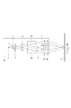
図1は、速度計のヘッド部の構成例を示す図である。ここで、検出部としてのヘッド部100は、物体(計測対象物)10に光を照射し、物体10からの光を受光するための光学系を含み、レーザードップラ速度計のヘッド部を構成している。レーザーダイオードを含みうる光源1から出射した光束9は、コリメータレンズ2によりコリメートされ、回折格子(回折素子)3に入射する。回折格子3に入射した光束9は、±1次回折光(回折角はθ)に分岐され、それぞれがレンズ4により集光光束となり、EO素子5a、5bを透過する。透過した2つの光束は、レンズ6a、6bによりコリメートされ、上記回折角θと略等しい角度で互いに異なる照射方向から物体10を照射する。照射された光束は、物体10の表面(一般に粗面)で拡散反射される。拡散反射された光束は、レンズ6a、6b、集光レンズ7を介して集光され、フォトダイオードを含みうる受光素子8に入射する。受光素子8での光電変換により得られた信号は、物体10の速度Vに応じた周波数Fを有し強度変調されたアナログ信号として、後述の処理部に入力される。ここで、当該周波数Fは、ドップラ周波数と呼ばれ、次式(1)で表される。
F=2V/P+F_EO ・・・(1)
FIG. 1 is a diagram illustrating a configuration example of a head portion of a speedometer. Here, the
F = 2V / P + F_EO (1)
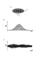
ここで、Pは、回折格子3の格子ピッチ、F_EOは、EO素子5a、5bの駆動周波数を示す。ドップラ効果を利用したレーザードップラ速度計の動作原理を説明するモデルとして、フリンジ(干渉縞)モデルが知られている。図2は、フリンジモデルを説明するための模式図である。物体10を照射する2つの光束が物体10の表面上で交差することで、図2の(a)に示すようなフリンジ11が形成される。このフリンジ11のフリンジピッチ以下のサイズの粒子12が速度Vでフリンジ11(の明部および暗部)を通過することで、図2の(b)に示すような周波数Fを有し強度変調された拡散光が発生する。この場合の周波数Fは、次式(2)のように表わされる。
F=V/P_i ・・・(2)
Here, P represents the grating pitch of the diffraction grating 3, and F_EO represents the drive frequency of the
F = V / P_i (2)
ここで、P_iは、フリンジピッチを示す。回折角θは、光源1から出射される光束9の波長をλとして、関係式sinθ=λ/Pから導かれる。また、物体10上での光束の入射角を回折角θと等しくなるように構成した場合、フリンジピッチP_iは、P_i=λ/2sin(θ)=P/2と表せる。この関係式と式(2)とより、式(1)の右辺第1項が導出される。また、図2の(b)の低周波成分(包絡線の成分)は、光源1から出射する光束9の強度分布を反映しており、典型的には、ガウシアン分布を反映したものとなりうる。物体10の表面は、ランダムな表面粗さを持っており、複数のランダムな特性をもった粒子12の集合とみなしうる。そこで、複数のランダムな位相、振幅を持もった図2の(b)のような信号の総和をとると、図2の(c)のような信号が得られる。ここで、図6は、後述の処理部101に入力されるアナログ信号を例示する図である。フリンジモデルにしたがって得られた図2の(c)の信号が図6の実際の信号に類似していることから、レーザードップラ速度計の動作原理をフリンジモデルが説明できることが分かる。
Here, P_i indicates a fringe pitch. The diffraction angle θ is derived from the relational expression sin θ = λ / P, where λ is the wavelength of the light beam 9 emitted from the
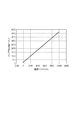
次に、式(1)の右辺第2項について説明する。図2の(c)の信号は、物体の速度を反映した高周波成分と、物体10の表面の特性を反映した低周波成分とを有するため、速度Vが0に近づくと、信号から速度を得ることが困難になる。また、速度Vの方向を検出することができない。そこで、図1においてEO素子が構成されている。ここで、EO素子5a、5bは、例えば、電気光学結晶(例えばLiNbO3結晶を含む)を含んで構成され電気光学的位相変調素子としうる。このような素子を含むことにより、物体の停止状態でもその速度が得られ、また、速度の方向が得られる。EO素子5a、5bは、印加電圧により、それを透過する光束の位相を変化させることができる。EO素子5a、5bで、それらをそれぞれ透過する2つの光束を、一定の周波数F_EOで互いに逆方向に位相が変化するように変調すると、フリンジ11がその1ピッチずつ周波数F_EOで移動することになる。例えば、EO素子5a、5bへの印加電圧を鋸歯状に変化させることにより、見かけ上の位相変化を一定にしうる。このように、フリンジ11が周波数F_EOで移動している中に静止した粒子12が置かれたとすると、周波数F_EOで強度変調される拡散反射光が発生する。つまり、ある方向に速度がオフセットされた場合と等価となる。したがって、このようにEO素子5a、5bを含んでレーザードップラ速度計を構成することにより、静止状態(速度ゼロ)および速度の方向の検出が可能となる。例えば、回折格子3の格子ピッチP=5[μm]、F_EO=200[kHz]とした場合の速度Vとドップラ周波数Fとの関係を図3に示した。ここで、図3は、物体の速度とドップラ周波数との関係を例示する図である。後述の処理部で信号処理できる信号の周波数の下限を100[kHz]、上限を4.2[MHz]とすると、測定可能な速度範囲は、−250[mm/s]ないし10[m/s]の範囲となる。なお、格子ピッチP、位相変調周波数F_EOの値は、レーザードップラ速度計の仕様に応じて、適宜選択することができる。また、ここでは、EO素子で位相変調を行う例を示したが、音響光学素子のような他の素子で位相変調を行うようにしてもよい。
Next, the second term on the right side of Equation (1) will be described. The signal shown in FIG. 2C has a high-frequency component reflecting the speed of the object and a low-frequency component reflecting the surface characteristics of the
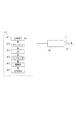
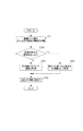
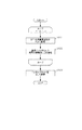
図4は、速度計の構成例を示す図である。上記のようにヘッド部100で得られた周波数Fを有する強度変調信号は、処理部101に入力される。入力端子401を介して処理部に入力されたアナログ信号は、ゲインアンプ402で増幅された後、バンドパスフィルタ(BPF)403でフィルタリング(濾波)され、コンパレータ404で2値化される。2値化により得られた信号に基づいて、演算部405で速度(の情報)が得られ、得られた速度(の情報)が出力端子406から出力される。
FIG. 4 is a diagram illustrating a configuration example of the speedometer. The intensity modulation signal having the frequency F obtained by the
図5は、信号処理内容を例示する図である。図5は、物体10の速度V=9500[mm/s]、ドップラ周波数F=4[MHz]の場合において、(a)は、入力信号を示し、(b)は、コンパレータでの2値化により得られる信号を示している。図5の(c)は、処理部101における(基準)クロック信号を示した図である。当該クロック信号を与える不図示の基準クロックは、処理部の内外のいずれにあってもよい。ここでは、基準クロック周波数を40[MHz]としている。本実施形態は、二値化により得られた信号における連続したN個分の立ち上がり間隔を基準クロックで計時(計数)する。ここで、1個分の立ち上がり間隔は、互いに隣接する2つのパルスにおける2つの立ち上がり時刻の間の時間間隔である。そして、計時により得られた時間(期間D)に基づいて、ドップラ周波数Fを得、式(1)に基づいて物体10の速度V(の情報)を取得する。ここでは、N=4としている。図5の(b)および(c)の場合、2値化により得られた信号における4個分の立ち上がり間隔の計数値は40(カウント)である。なお、基準クロックの周波数は既知であるため、計数値(計時値)からドップラ周波数Fを得ることができる。また、速度Vは、式(1)に基づく計算によって得てもよいし、計数値(計時値)と速度との関係を示す予め準備したテーブルの参照によって得てもよい。基準クロックの周波数は、ここでは40MHzとしたが、必要なドップラ周波数に応じて適宜選択しうる。
FIG. 5 is a diagram illustrating the contents of signal processing. FIG. 5A shows an input signal and FIG. 5B shows binarization by a comparator when the velocity of the
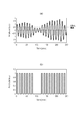
図6は、上述したように、処理部101に入力されるアナログ信号を例示する図である。図6の(b)は、図6の(a)の一部を拡大して表示している。上述したように、ヘッド部100から出力される信号は、ドップラ信号に原理的に生じる振幅の変化が大きい信号である。また、電気回路に生ずるノイズ(例えば、電源のスイッチングノイズ、EO素子の駆動に伴うノイズ)が光源1を駆動する電流に重畳することから、ヘッド部100から出力される信号には、ドップラ信号以外に、低周波、高周波のノイズが混入している。図6の(b)において矢印で指し示される信号の状態は、低周波成分の振幅が小さい状態である。ここで、コンパレータによる2値化の閾値を下回る状態(部分)では、当該2値化により得られる信号はゼロとなる(欠落する)。このような状態は、ドロップアウトとも呼ばれている。また、高周波ノイズ成分により当該閾値を上回るような状態(部分)では、2値化により得られる信号にドップラ信号とは異なる信号が含まれうる。
FIG. 6 is a diagram illustrating an analog signal input to the
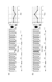
図7は、処理部における演算部での処理の流れを例示する図である。図4の処理部101において、コンパレータでの2値化により得られた信号は、演算部405に入力される。まず、ステップS701において、演算部405は、2値化により得られた信号における連続した(一連の)N個の立ち上がり間隔(パルス間隔)の時間(所定数のパルスにわたる期間)を図5に示したように基準クロックにより計時(計数)する。つづくステップS702において、当該期間(計時値)に関する指標の変化が閾値を超えるかを判定する。ここで、当該指標は、上記の期間Dでもよく、該期間Dに対応するドップラ周波数Fでもよく、該ドップラ周波数Fに対応する物体10の速度Vでもよく、またはそれらに相関のある他の値でもよい。ここで、図8は、ドロップアウトが発生した場合の信号を例示する図である。図8の(a)のように、時刻100μsecのあたりでドップラ信号を含むアナログ信号にドロップアウトが発生した場合、図8の(b)のように、2値化により得られた信号においてパルスが抜ける。また、図9は、ノイズが混入した場合の信号を例示する図である。図9の(a)のように、時刻3μsecのあたりでドップラ信号を含むアナログ信号にノイズが混入した場合、図9の(b)のように、2値化により得られた信号においてパルスが割れる。
FIG. 7 is a diagram illustrating a flow of processing in the calculation unit in the processing unit. In the
図10は、誤りとされる計測値を例示する図である。同図の(a)は、図8に示したようなドロップアウトがある場合に得られる速度(計測値)を例示している。N=4個毎の立ち上がり間隔を計時していくと、ドロップアウトに起因するパルス抜けが生じた結果、基準クロックの計数値が50カウントとなる場合が生じている。これらの計時値に基づいて速度を得ると、同図(a)右側のグラフのようになる。なお、ドロップアウトによるパルス抜けの数が増大すると計測値の誤差も増大する。次に、図10の(b)は、図9に示したようなノイズが混入した場合に得られる速度(計測値)を例示している。この場合も、N=4個毎の立ち上がり間隔を計時していくと、ノイズ混入に起因するパルス割れが生じた結果、基準クロックの計数値が30カウントとなる場合が生じている。これらの計時値に基づいて速度を得ると、同図(b)右図のグラフのようになる。なお、ノイズ混入によるパルス割れの数が増大すると計測値の誤差も増大する。 FIG. 10 is a diagram illustrating an example of a measurement value that is regarded as an error. (A) of the figure illustrates the speed (measured value) obtained when there is a dropout as shown in FIG. When the rising intervals of every N = 4 are counted, there is a case where the count value of the reference clock becomes 50 counts as a result of missing pulses due to dropout. When the speed is obtained based on these measured values, the graph on the right side of FIG. Note that the error in the measured value increases as the number of missing pulses due to dropout increases. Next, FIG. 10B illustrates the speed (measured value) obtained when noise as shown in FIG. 9 is mixed. In this case as well, when the rising intervals of every N = 4 are counted, there is a case where the count value of the reference clock becomes 30 counts as a result of the occurrence of pulse cracking due to noise mixing. When the speed is obtained based on these timekeeping values, the graph shown in the right figure of FIG. As the number of pulse cracks due to noise increases, the error in the measured value also increases.
時系列に連続して取得される計数値の変化は、所定時間内での物体10の速度変化を考慮すれば、所定の範囲内にあると考えうる。例えば、物体10の速度Vが、現在9.5[m/s]であって、10[m/s^2]の加速度で変化する場合、N=4個毎の期間Dにおける速度変化は10[μm/s]に過ぎない。この速度変化の速度に対する割合は、速度に反比例するが、V=0.1[m/s]の場合であっても、速度変化は0.17[mm/s]程度であって十分小さいといえる(割合は0.17%程度)。以上のことから、上記指標の変化が、(前もって得られている)指標のL[%]を超える場合、ドロップアウトまたはノイズ混入が生じたと判定しうる。Lは、次式(3)で表される。
L=((N+1)/N−1)×100 ・・・(3)
The change in the count value acquired continuously in time series can be considered to be within a predetermined range in consideration of the speed change of the
L = ((N + 1) / N−1) × 100 (3)
よって、図7のステップS702における閾値は、(前もって得られている)指標のL[%]として得ることができる。そして、指標の変化が閾値(指標のL[%])以下である場合は、ステップS703で、計時値に基づいて速度(計測値)を得る。一方、指標の変化が閾値(指標のL[%])を超える場合は、ステップS704で、それに対応する速度は誤りであるとして前もって得られた速度を計測値とする。つづくステップS705において、処理部101は、速度の情報を必要とする他の装置に速度(計測値)を出力する。なお、閾値は、指標のa×L[%](係数aは0<a<1を満たす実数)としてもよい。
Therefore, the threshold value in step S702 in FIG. 7 can be obtained as L [%] of an index (obtained in advance). If the change in the index is equal to or less than the threshold value (L [%] of the index), the speed (measured value) is obtained based on the time measured value in step S703. On the other hand, if the change in the index exceeds the threshold value (L [%] of the index), in step S704, the speed obtained in advance as the speed corresponding to the error is set as the measurement value. In step S705, the
図11は、補正前の計測値と補正後の計測値とを例示する図である。図11において、物体10が速度V≒9.5[m/s]で移動した場合の速度の計測結果を示している。図11の(a)は、本実施形態に係る補正(ステップS702ないしS704)を行わなかった場合の計測結果、同図の(b)は、当該補正を行った場合の計測結果を示している。図11を参照するに、本実施形態によれば、同図の(b)におけるように高精度(高再現性)の計測結果を得られることが分かる。
FIG. 11 is a diagram illustrating a measurement value before correction and a measurement value after correction. FIG. 11 shows a measurement result of the speed when the
以上説明したように、本実施形態によれば、ドロップアウトのみならずノイズの混入に対してロバストな計測を行うことができ、もって、例えば、計測精度の点で有利な速度計を提供することができる。 As described above, according to this embodiment, it is possible to perform robust measurement not only with respect to dropout but also with noise, and thus provide a speedometer that is advantageous in terms of measurement accuracy, for example. Can do.
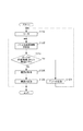
つづいて、処理部101の別の側面について説明する。図4に示した処理部101のバンドパスフィルタ(BPF)403は、ドップラ周波数以外の周波数を有するノイズを低減するために用意されている。ここで、BPF403のQ値は、それには限定されないが、6程度に設定している。ドップラ周波数は、広帯域にわたるため、BPFは、共振周波数(中心周波数)を可変にしたBPFを採用している。当該BPFは、例えば、RLCフィルタのR、L、Cのうちの少なくとも1つを可変にして実現しうる。図12は、信号処理の流れを例示する図である。まず、ステップS1201において、後述のサーチによりBPFの共振周波数を決定する。つづくステップS1202で、BPFの共振周波数を設定する。ステップS1203において、処理部101に入力されたアナログ信号がBPFによりフィルタリング(濾波)されてコンパレータに入力される。ここで、濾波により得られた信号に対してレベルの判定を行う。図6に示したようなアナログ信号であれば、BPFでのフィルタリングにより信号処理が可能である。しかし、物体10の表面状態によっては、図13に示すアナログ信号となって、長期間にわたってドロップアウトが発生しうる。ここで、図13は、処理部に入力されるアナログ信号の別の例を示す図である。このような信号では、正確な速度計測を実施することは困難である。そこで、ステップS1203においては、BPFでフィルタリングされて得られた信号の振幅に対して、ピークホールド処理を行い、ホールドされたピークが予め設定した時間にわたり予め設定した閾値以下かを判定する。そうなる場合(Yesの場合)、エラーと判定して出力し(ステップS1204)、ステップS1201(サーチ)に処理を戻す。一方、そうはならない場合(Noの場合)、BPFでのフィルタリングにより得られた信号は、コンパレータ404で2値化され、さらに演算部405で処理される。ステップS1205において、演算部405は、物体10の速度を得る。つづくステップS1205で、処理部101は、出力端子406から速度(情報)を別の装置に出力する。
Next, another aspect of the
図12におけるステップS1201(サーチ)は、信号処理部101に入力するアナログ信号におけるドップラ周波数に応じてBPFの共振周波数を決定するステップである。ここで、図14は、S1201(サーチ)における処理の流れの例を示す図である。i=1、2、・・・、qに関して、ステップS1401およびステップS1402を繰り返す(ループする)。ステップS1401では、BPFの共振周波数F(i)を設定する。つづくステップS1402では、濾波により得られた信号の振幅値A(i)を取得する。ループを抜けたステップS1403では、A(i)が最大となるi=i_maxを得る。つづくステップS1404では、F(i_max)をBPFの共振周波数として決定する。ここで、図17は、S1201(サーチ)およびS1601(キャリブレーション)における信号処理内容に係る例を示す図である。キャリブレーションについては後述する。この例では、濾波により得られた信号の振幅が約700[kHz]で最大になっている。このため、ドップラ周波数は約700[kHz]であることを示していると考えうる。この考えのもとで、S1201(サーチ)では、BPFの共振周波数を決定しうる。
Step S1201 (search) in FIG. 12 is a step of determining the resonance frequency of the BPF in accordance with the Doppler frequency in the analog signal input to the
しかし、ドップラ信号のS/N比が低い場合、S1201(サーチ)において、ドップラ周波数とは掛け離れた周波数をBPFの共振周波数として決定してしまいうる。図18は、S1201(サーチ)およびS1601(キャリブレーション)における信号処理内容に係る第2例を示す図である。図18の(a)は、ドップラ信号のS/N比が低い場合に濾波により得られた信号の振幅値A(i)を示している。この例では、ドップラ周波数が約150[kHz]であるが、ヘッド部100の生成するノイズの影響で、約3[MHz]で振幅が最大になっている。ヘッド部100の有するノイズ成分は、個々のヘッド部に固有のものであり、ドップラ周波数によらない。したがって、このノイズの情報を予め取得することにより速度計のキャリブレーションが可能である。
However, when the S / N ratio of the Doppler signal is low, a frequency far from the Doppler frequency may be determined as the BPF resonance frequency in S1201 (search). FIG. 18 is a diagram illustrating a second example of signal processing contents in S1201 (search) and S1601 (calibration). FIG. 18A shows the amplitude value A (i) of the signal obtained by filtering when the S / N ratio of the Doppler signal is low. In this example, the Doppler frequency is about 150 [kHz], but the amplitude is maximum at about 3 [MHz] due to the influence of noise generated by the
図15は、図16におけるS1601(キャリブレーション)における処理の流れを例示する図である。S1601(キャリブレーション)は、ヘッド部固有のノイズ成分の情報を予め取得する工程であって、物体10を設置せずに実施される。i=1、2、・・・、qに関して、ステップS1501およびステップS1502を繰り返す(ループする)。まず、ステップS1501では、BPFの共振周波数F(i)を設定する。つづくステップS1502では、濾波により得られた信号の振幅値C(i)を取得する。ループを抜けたステップS1503では、C(i)をオフセット値(キャリブレーション値)として、例えば処理部101内の、メモリに記憶させる。ここで、図17の(b)および図18の(b)は、物体10を設置しないで取得され記憶されているオフセット値C(i)の例である。
FIG. 15 is a diagram illustrating a processing flow in S1601 (calibration) in FIG. S1601 (calibration) is a step of acquiring information about noise components unique to the head portion in advance, and is performed without installing the
図16は、S1201(サーチ)における処理の流れの第2例を示す図である。図14の処理の流れにおける処理とは同様の処理は、同一または類似の符号を付して説明を省略する。まず、ステップS1601(キャリブレーション)は、図15を参照して説明した処理である。ステップS1602においては、物体10を設置した状態で取得したF(i)での振幅値A(i)からステップS1601で得られたオフセット値C(i)を差し引いて、ヘッド部100に固有のノイズ成分の影響を低減した振幅値A´(i)を取得する。ここで、図17の(c)および図18の(c)は、振幅値A´(i)の例である。図16に係る処理を実行することにより、ドップラ信号のS/N比が低い場合でも、BPFの共振周波数をより的確に決定することができる。また、図12に係る処理におけるステップS1203(ピーク判定)でエラーと判定された場合に再びステップS1201(サーチ)の処理を実施すれば、図13におけるような信号から図6におけるような信号に変化した場合に直ちに計測を再開できる。
FIG. 16 is a diagram showing a second example of the processing flow in S1201 (search). Processes similar to those in the process flow of FIG. 14 are denoted by the same or similar reference numerals, and description thereof is omitted. First, step S1601 (calibration) is the process described with reference to FIG. In step S1602, the noise inherent in the
以上のように、図12ないし図18を参照して説明したような処理を実施すれば、速度計において速度を取得するロバストな処理が可能となる。なお、バンドパスフィルタ(BPF)403の共振周波数の設定は、例えば、速度計が速度計測を開始する場合(開始の直前等)や、速度計測に誤りがあった(所定の条件を満たして誤りが継続した)場合等において実行しうる。また、速度計測を実行している間は、速度の計測値に基づいて共振周波数を設定(変更)しうる。 As described above, if processing such as that described with reference to FIGS. 12 to 18 is performed, robust processing for acquiring the speed in the speedometer becomes possible. Note that the resonance frequency of the bandpass filter (BPF) 403 is set, for example, when the speedometer starts speed measurement (immediately before the start), or there is an error in speed measurement (an error that satisfies a predetermined condition). Can be executed in the case where the Further, while the speed measurement is being performed, the resonance frequency can be set (changed) based on the speed measurement value.
〔実施形態2〕
実施形態1では、演算部405(ステップS702)において、指標の変化が閾値を超えるかの判定は、直前に(前もって)得られた指標に基づく閾値に基づいて実施した。しかしながら、当該閾値は、直前に(前もって)得られたM個の指標(例えば、それらの平均値)に基づく閾値としてもよい。また、当該平均値は、単純な平均値ではなく、加重平均値、相乗平均値またはその他の平均値としうる。また、実施形態1では、ステップS704で、得られた速度が誤りであるとして前もって得られた速度を計測値とするものとしたが、これに替えて、前もって得られた複数の計測値(例えば、それらの平均値)に基づく速度を計測値としてもよい。また、当該平均値は、単純な平均値ではなく、加重平均値、相乗平均値またはその他の平均値としうる。例えば、物体10の速度変動が小さいことが予め分かっていれば、Mの値を大きくすることにより安定した計測が可能となる。また、速度変動の大きさが概ね予め分かっている場合、当該大きさに基づいてMの値を可能な限り小さくすることにより、エラー判定に係る閾値の追従性(妥当性)を改善することができる。発明者らの検討によれば、物体10の加速度が1[G]程度の場合、M=16以下にすることにより追従性が改善することが分かっている。
[Embodiment 2]
In the first embodiment, the calculation unit 405 (step S702) determines whether the change in the index exceeds the threshold based on the threshold based on the index obtained immediately before (in advance). However, the threshold value may be a threshold value based on M indexes (for example, average values thereof) obtained immediately before (in advance). In addition, the average value is not a simple average value but can be a weighted average value, a geometric average value, or another average value. Further, in the first embodiment, in step S704, it is assumed that the speed obtained in advance as the measured speed is an error, but instead of this, a plurality of measurement values obtained in advance (for example, A speed based on the average value thereof may be a measured value. In addition, the average value is not a simple average value but can be a weighted average value, a geometric average value, or another average value. For example, if it is known in advance that the speed fluctuation of the
〔物品製造方法に係る実施形態〕
以上に説明した実施形態に係る速度計は、物品製造方法に使用しうる。当該物品製造方法は、当該速度計を用いて物体の速度を計測する工程と、当該工程で速度を計測された物体を処理する工程と、を含みうる。当該処理は、例えば、加工、切断、検査、組付、および選別のうちの少なくともいずれか一つを含みうる。より具体的には、例えば、押出成形機による成形物の押出速度を計測して当該成形物の押出速度を制御しうる。また、搬送系により搬送される(長尺)物体の速度を計測し、当該計測により得られた速度を積分して物体の測長を行い、当該測長に基づいて、目標とする長さを有するように物体を切断し(切り出し)うる。本実施形態の物品製造方法は、速度計により非接触で高精度に物体の速度を計測できるため、従来の方法に比べて、物品の性能・品質・生産性・生産コストのうちの少なくとも1つにおいて有利である。
[Embodiment related to article manufacturing method]
The speedometer according to the embodiment described above can be used in an article manufacturing method. The article manufacturing method may include a step of measuring the speed of an object using the speedometer and a step of processing the object whose speed is measured in the step. The process can include, for example, at least one of processing, cutting, inspection, assembly, and selection. More specifically, for example, the extrusion speed of the molding can be controlled by measuring the extrusion speed of the molding with an extruder. Also, the speed of the (long) object transported by the transport system is measured, the speed obtained by the measurement is integrated, the object is measured, and the target length is determined based on the measured length. The object can be cut (cut out) to have. Since the article manufacturing method of the present embodiment can measure the speed of an object with high accuracy in a non-contact manner using a speedometer, at least one of the performance, quality, productivity, and production cost of the article compared to the conventional method Is advantageous.
以上、本発明の好ましい実施形態について説明したが、本発明はこれらの実施形態に限定されないことはいうまでもなく、その要旨の範囲内で種々の変形および変更が可能である。 As mentioned above, although preferred embodiment of this invention was described, it cannot be overemphasized that this invention is not limited to these embodiment, A various deformation | transformation and change are possible within the range of the summary.
100 検出部(ヘッド部)
101 処理部
100 Detection part (head part)
101 processing unit
Claims (15)
前記光を検出する検出部と、
前記検出部により得られた信号を2値化し、該2値化により得られた信号における所定数のパルス間隔にわたる期間を計って前記速度の計測値を得る処理部と、を有し、
前記処理部は、前記期間に関する指標の変化に基づいて前記計測値を誤りとすることを特徴とする速度計。 A speedometer that detects light modulated by the Doppler effect by a moving object and measures the speed of the object,
A detector for detecting the light;
A processor that binarizes the signal obtained by the detector and obtains a measured value of the speed by measuring a period over a predetermined number of pulse intervals in the signal obtained by the binarization,
The said processing part makes the said measured value an error based on the change of the parameter | index regarding the said period, The speedometer characterized by the above-mentioned.
前記2つの光は、前記物体で反射されて前記検出部により検出されることを特徴とする請求項1ないし請求項3のうちいずれか1項に記載の速度計。 An optical system that irradiates the object with two light beams having different irradiation directions and phases opposite to each other;
The speedometer according to any one of claims 1 to 3, wherein the two lights are reflected by the object and detected by the detection unit.
前記工程で前記速度を計測された前記物体の処理を行う工程と、
を含むことを特徴とする物品製造方法。 A step of measuring the speed of an object using the speedometer according to any one of claims 1 to 14,
Processing the object whose speed has been measured in the step;
An article manufacturing method comprising:
Priority Applications (5)
| Application Number | Priority Date | Filing Date | Title |
|---|---|---|---|
| JP2015132151A JP2017015547A (en) | 2015-06-30 | 2015-06-30 | Speedometer and article manufacturing method |
| US15/197,021 US10408853B2 (en) | 2015-06-30 | 2016-06-29 | Velocimeter and method of manufacturing article |
| KR1020160081294A KR102052433B1 (en) | 2015-06-30 | 2016-06-29 | Velocimeter and method of manufacturing article |
| CN201610509486.0A CN106324274A (en) | 2015-06-30 | 2016-06-30 | Velocimeter and method of manufacturing an article |
| EP16177077.1A EP3112903B1 (en) | 2015-06-30 | 2016-06-30 | Velocimeter and method of manufacturing an article |
Applications Claiming Priority (1)
| Application Number | Priority Date | Filing Date | Title |
|---|---|---|---|
| JP2015132151A JP2017015547A (en) | 2015-06-30 | 2015-06-30 | Speedometer and article manufacturing method |
Related Child Applications (1)
| Application Number | Title | Priority Date | Filing Date |
|---|---|---|---|
| JP2020009841A Division JP6808859B2 (en) | 2020-01-24 | 2020-01-24 | Speedometer and article manufacturing method |
Publications (1)
| Publication Number | Publication Date |
|---|---|
| JP2017015547A true JP2017015547A (en) | 2017-01-19 |
Family
ID=56296635
Family Applications (1)
| Application Number | Title | Priority Date | Filing Date |
|---|---|---|---|
| JP2015132151A Pending JP2017015547A (en) | 2015-06-30 | 2015-06-30 | Speedometer and article manufacturing method |
Country Status (5)
| Country | Link |
|---|---|
| US (1) | US10408853B2 (en) |
| EP (1) | EP3112903B1 (en) |
| JP (1) | JP2017015547A (en) |
| KR (1) | KR102052433B1 (en) |
| CN (1) | CN106324274A (en) |
Families Citing this family (2)
| Publication number | Priority date | Publication date | Assignee | Title |
|---|---|---|---|---|
| CN116134340A (en) | 2020-08-05 | 2023-05-16 | 三菱电机株式会社 | Distance measuring device, distance measuring method and radar device |
| CN114758802B (en) * | 2022-04-01 | 2023-05-16 | 华能核能技术研究院有限公司 | Doppler heating point power determination method, device and storage medium |
Citations (8)
| Publication number | Priority date | Publication date | Assignee | Title |
|---|---|---|---|---|
| JPS6276915A (en) * | 1985-09-30 | 1987-04-09 | Nippon Kishiyou Kyokai Hokkaido Honbu | Automatic tuning band pass filter device |
| JPH01182784A (en) * | 1988-01-13 | 1989-07-20 | Japan Aviation Electron Ind Ltd | Laser doppler speedometer |
| JPH04218776A (en) * | 1990-10-30 | 1992-08-10 | Toshiba Corp | Current meter |
| JPH07128349A (en) * | 1993-10-28 | 1995-05-19 | Komatsu Ltd | Speed detector |
| JPH0815436A (en) * | 1994-06-28 | 1996-01-19 | Canon Inc | Error signal detector and doppler speedometer using the detector |
| JPH08304543A (en) * | 1995-05-09 | 1996-11-22 | Canon Inc | Frequency shifter and optical displacement measuring equipment using the same |
| US6437855B1 (en) * | 2000-07-13 | 2002-08-20 | Honeywell International Inc. | Laser doppler velocimeter with high immunity to phase noise |
| WO2015052839A1 (en) * | 2013-10-11 | 2015-04-16 | 三菱電機株式会社 | Wind measurement lidar device |
Family Cites Families (6)
| Publication number | Priority date | Publication date | Assignee | Title |
|---|---|---|---|---|
| US5187538A (en) * | 1990-10-30 | 1993-02-16 | Kabushiki Kaisha Toshiba | Laser doppler velocimeter |
| JPH06197015A (en) | 1992-12-24 | 1994-07-15 | Canon Inc | Frequency oscillator, period error detector, filter, signal deciding device and doppler velocity meter using them |
| JPH07270436A (en) * | 1994-03-31 | 1995-10-20 | Nkk Corp | Length measuring apparatus for moving object |
| US6272071B1 (en) * | 1997-11-26 | 2001-08-07 | Ricoh Microelectronics Co., Ltd. | Speed measuring apparatus |
| JP2016014616A (en) | 2014-07-03 | 2016-01-28 | アズビル株式会社 | Velocity transition measuring device and velocity transition measuring method |
| JP6614827B2 (en) * | 2015-06-30 | 2019-12-04 | キヤノン株式会社 | Length measuring device and article manufacturing method |
-
2015
- 2015-06-30 JP JP2015132151A patent/JP2017015547A/en active Pending
-
2016
- 2016-06-29 US US15/197,021 patent/US10408853B2/en active Active
- 2016-06-29 KR KR1020160081294A patent/KR102052433B1/en active IP Right Grant
- 2016-06-30 CN CN201610509486.0A patent/CN106324274A/en active Pending
- 2016-06-30 EP EP16177077.1A patent/EP3112903B1/en active Active
Patent Citations (8)
| Publication number | Priority date | Publication date | Assignee | Title |
|---|---|---|---|---|
| JPS6276915A (en) * | 1985-09-30 | 1987-04-09 | Nippon Kishiyou Kyokai Hokkaido Honbu | Automatic tuning band pass filter device |
| JPH01182784A (en) * | 1988-01-13 | 1989-07-20 | Japan Aviation Electron Ind Ltd | Laser doppler speedometer |
| JPH04218776A (en) * | 1990-10-30 | 1992-08-10 | Toshiba Corp | Current meter |
| JPH07128349A (en) * | 1993-10-28 | 1995-05-19 | Komatsu Ltd | Speed detector |
| JPH0815436A (en) * | 1994-06-28 | 1996-01-19 | Canon Inc | Error signal detector and doppler speedometer using the detector |
| JPH08304543A (en) * | 1995-05-09 | 1996-11-22 | Canon Inc | Frequency shifter and optical displacement measuring equipment using the same |
| US6437855B1 (en) * | 2000-07-13 | 2002-08-20 | Honeywell International Inc. | Laser doppler velocimeter with high immunity to phase noise |
| WO2015052839A1 (en) * | 2013-10-11 | 2015-04-16 | 三菱電機株式会社 | Wind measurement lidar device |
Non-Patent Citations (1)
| Title |
|---|
| 三品 博達: ""技術ノート(時系列信号のスペクトル解析) バースト信号の周期解析"", 応用物理 第52巻 第5号, vol. 第52巻, 第5号, JPN6019014275, 10 May 1983 (1983-05-10), pages 424 - 52, ISSN: 0004021116 * |
Also Published As
| Publication number | Publication date |
|---|---|
| EP3112903B1 (en) | 2020-04-29 |
| CN106324274A (en) | 2017-01-11 |
| KR20170003445A (en) | 2017-01-09 |
| US10408853B2 (en) | 2019-09-10 |
| EP3112903A1 (en) | 2017-01-04 |
| KR102052433B1 (en) | 2019-12-05 |
| US20170003312A1 (en) | 2017-01-05 |
Similar Documents
| Publication | Publication Date | Title |
|---|---|---|
| JP6614827B2 (en) | Length measuring device and article manufacturing method | |
| US10054529B2 (en) | Particle counter | |
| US4334779A (en) | Non-contact optical apparatus for measuring the length or speed of a relatively moving surface | |
| JP2005227077A (en) | Optical moving information detector, moving information detecting system, electronic equipment, and encoder | |
| US10416069B2 (en) | Particle counter | |
| KR102166583B1 (en) | Particle counter | |
| KR102052433B1 (en) | Velocimeter and method of manufacturing article | |
| JPH06197015A (en) | Frequency oscillator, period error detector, filter, signal deciding device and doppler velocity meter using them | |
| JP6808859B2 (en) | Speedometer and article manufacturing method | |
| US4115005A (en) | Method for optically measuring a roughness profile of surface | |
| US6844537B2 (en) | Method and device for measuring the velocity of a moving surface | |
| JP2006322912A (en) | Device and method for measuring laser length | |
| JPS60243583A (en) | Laser doppler speedometer | |
| JP3491975B2 (en) | Error signal detecting device and Doppler velocimeter using the same | |
| Sidorov et al. | Distance sensing using dynamic speckles formed by micro-electro-mechanical-systems deflector | |
| RU83138U1 (en) | Sperm Fertility Analyzer | |
| GB2468177A (en) | Optical surface measuring apparatus and method | |
| JPH0821849A (en) | Measuring method for high-temperature body by laser doppler system | |
| SU354346A1 (en) | METHOD OF MEASURING THE SPEED OF MOTION OF AN EXTENDED OBJECT | |
| JP3491988B2 (en) | Laser doppler speedometer | |
| KR20220159688A (en) | Particulates measuring method and particulates measuring device | |
| RU43066U1 (en) | OPTOELECTRONIC DEVICE FOR MEASURING LINEAR MOVEMENTS OF OBJECT | |
| JPS60224001A (en) | Microsize measuring instrument | |
| JPH07301673A (en) | Speedometer, speed detecting method and displacement information detecting device | |
| Nippolainen et al. | Detection of surface defects by means of dynamic speckles |
Legal Events
| Date | Code | Title | Description |
|---|---|---|---|
| A621 | Written request for application examination |
Free format text: JAPANESE INTERMEDIATE CODE: A621 Effective date: 20180601 |
|
| A977 | Report on retrieval |
Free format text: JAPANESE INTERMEDIATE CODE: A971007 Effective date: 20190405 |
|
| A131 | Notification of reasons for refusal |
Free format text: JAPANESE INTERMEDIATE CODE: A131 Effective date: 20190423 |
|
| A521 | Request for written amendment filed |
Free format text: JAPANESE INTERMEDIATE CODE: A523 Effective date: 20190621 |
|
| A131 | Notification of reasons for refusal |
Free format text: JAPANESE INTERMEDIATE CODE: A131 Effective date: 20191126 |
|
| A02 | Decision of refusal |
Free format text: JAPANESE INTERMEDIATE CODE: A02 Effective date: 20200707 |