JP2017015409A - Road surface detection device, mobile body, road surface detection method, and road surface detection program - Google Patents
Road surface detection device, mobile body, road surface detection method, and road surface detection program Download PDFInfo
- Publication number
- JP2017015409A JP2017015409A JP2015129097A JP2015129097A JP2017015409A JP 2017015409 A JP2017015409 A JP 2017015409A JP 2015129097 A JP2015129097 A JP 2015129097A JP 2015129097 A JP2015129097 A JP 2015129097A JP 2017015409 A JP2017015409 A JP 2017015409A
- Authority
- JP
- Japan
- Prior art keywords
- road surface
- detection
- surface information
- distance
- obstacle
- Prior art date
- Legal status (The legal status is an assumption and is not a legal conclusion. Google has not performed a legal analysis and makes no representation as to the accuracy of the status listed.)
- Pending
Links
- 238000001514 detection method Methods 0.000 title claims abstract description 167
- 238000005259 measurement Methods 0.000 claims abstract description 109
- 238000012937 correction Methods 0.000 claims abstract description 40
- 230000007704 transition Effects 0.000 claims description 3
- 238000000605 extraction Methods 0.000 description 19
- 238000010586 diagram Methods 0.000 description 12
- 238000000034 method Methods 0.000 description 7
- 238000012545 processing Methods 0.000 description 7
- 101150081243 STA1 gene Proteins 0.000 description 4
- 230000007613 environmental effect Effects 0.000 description 3
- 101100366889 Caenorhabditis elegans sta-2 gene Proteins 0.000 description 2
- 239000000470 constituent Substances 0.000 description 2
- HBBGRARXTFLTSG-UHFFFAOYSA-N Lithium ion Chemical compound [Li+] HBBGRARXTFLTSG-UHFFFAOYSA-N 0.000 description 1
- 229910003307 Ni-Cd Inorganic materials 0.000 description 1
- 238000004364 calculation method Methods 0.000 description 1
- 238000004891 communication Methods 0.000 description 1
- 230000007547 defect Effects 0.000 description 1
- 239000000284 extract Substances 0.000 description 1
- 239000000446 fuel Substances 0.000 description 1
- 238000012417 linear regression Methods 0.000 description 1
- 229910001416 lithium ion Inorganic materials 0.000 description 1
- 239000011159 matrix material Substances 0.000 description 1
- 229910052987 metal hydride Inorganic materials 0.000 description 1
- 239000000203 mixture Substances 0.000 description 1
- 229910052759 nickel Inorganic materials 0.000 description 1
- PXHVJJICTQNCMI-UHFFFAOYSA-N nickel Substances [Ni] PXHVJJICTQNCMI-UHFFFAOYSA-N 0.000 description 1
- -1 nickel metal hydride Chemical class 0.000 description 1
- 230000003287 optical effect Effects 0.000 description 1
- 230000000007 visual effect Effects 0.000 description 1
Images


Abstract
Description
本発明は、路面までの距離を測定する測距センサを備えた路面検知装置および移動体、並びに、その路面検知方法および路面検知プログラムに関する。 The present invention relates to a road surface detection device and a moving body that include a distance measuring sensor that measures a distance to a road surface, and a road surface detection method and a road surface detection program thereof.
従来、路面を自律走行する移動体では、センサなどで障害物を検知して、動作を制御していた。このような移動体では、障害物に加えて路面も検知しており、走行可能な領域かどうかを判断していた。例えば、移動体に環境地図生成制御装置を設けることが提案されており、環境地図生成制御装置では、路面状態を判定して、移動可能または移動不可能な領域が登録された環境地図を生成している(例えば、特許文献1参照。)。 Conventionally, in a moving body that autonomously travels on a road surface, an obstacle is detected by a sensor or the like to control the operation. In such a moving body, a road surface is detected in addition to an obstacle, and it is determined whether or not the vehicle is in a travelable area. For example, it has been proposed to provide an environment map generation control device on a moving body, and the environment map generation control device determines a road surface state and generates an environment map in which a movable or non-movable region is registered. (For example, refer to Patent Document 1).
特許文献1に記載の移動体の環境地図生成制御装置は、測距手段によって平坦路に向けてパルスレーザを照射しており、受光したパルス幅と算出した平坦路の視野幅とを比較し、路面状態を判定して環境地図を生成している。このように、特許文献1では、環境地図を生成することで、平坦路を障害物であるとの誤認を防止している。ところで、パルス幅に基づいて、環境地図を生成する場合には、上り坂や障害物などを混同することが懸念されるため、異なる方法で路面を検知することが求められている。
The environmental map generation control device for a moving body described in
本発明は、上記の課題を解決するためになされたものであり、路面の傾斜を推定することで、路面の勾配を把握することができる路面検知装置、移動体、路面検知方法、および路面検知プログラムを提供することを目的とする。 The present invention has been made to solve the above-described problems, and a road surface detection device, a moving body, a road surface detection method, and road surface detection capable of grasping the road surface gradient by estimating the road surface inclination. The purpose is to provide a program.
本発明に係る路面検知装置は、被検知物に対する検知波を送波し、該被検知物からの反射波を受波して、該被検知物までの検知距離を測定する測距センサと、前記測距センサの測距結果に基づいて、前記検知波が送波された検知範囲における路面の状態を示す路面情報を生成する路面情報生成部と、前記路面情報に基づいて、前記路面の傾斜を推定し、該路面情報を補正する路面情報補正部と、前記検知範囲内に障害物があるか否かの障害物判定をする障害物判定部と、前記路面情報に基づいて、前記検知範囲内で前記障害物判定が無効とされる無効領域を設定する無効領域設定部とを備えていることを特徴とする。 A road surface detection device according to the present invention transmits a detection wave to a detected object, receives a reflected wave from the detected object, and measures a detection distance to the detected object; and A road surface information generating unit that generates road surface information indicating a state of a road surface in a detection range where the detection wave is transmitted based on a distance measurement result of the distance measuring sensor, and an inclination of the road surface based on the road surface information Based on the road surface information, a road surface information correction unit that corrects the road surface information, an obstacle determination unit that determines whether there is an obstacle in the detection range, and the road surface information. And an invalid area setting unit for setting an invalid area where the obstacle determination is invalid.
本発明に係る路面検知装置では、前記路面情報は、予め決められた走査方向に沿って並んだ複数の測定点が設定され、前記測距センサは、前記測定点毎に、該測距センサを基準とした検知高度を出力する構成とされ、前記路面情報補正部は、前記走査方向に沿った前記検知高度の推移から、前記路面の傾斜を推定することを特徴とする。 In the road surface detection device according to the present invention, the road surface information is set with a plurality of measurement points arranged along a predetermined scanning direction, and the distance measurement sensor detects the distance measurement sensor for each measurement point. The road surface information correction unit is configured to output a reference detection altitude, and the road surface information correction unit estimates the inclination of the road surface from the transition of the detection altitude along the scanning direction.
本発明に係る路面検知装置では、前記測距センサは、上面視において、該測距センサが設けられた位置から離間した路面に向かって前記検知波を照射しており、前記走査方向は、上面視において、前記検知波の照射方向と一致している構成としてもよい。 In the road surface detection device according to the present invention, the distance measurement sensor irradiates the detection wave toward a road surface separated from a position where the distance measurement sensor is provided in a top view, and the scanning direction is the upper surface. It is good also as a structure which corresponds with the irradiation direction of the said detection wave in view.
本発明に係る路面検知装置では、前記測距センサは、上面視において、該測距センサが設けられた位置から離間した路面に向かって前記検知波を照射しており、前記走査方向は、上面視において、前記検知波の照射方向と直交している構成としてもよい。 In the road surface detection device according to the present invention, the distance measurement sensor irradiates the detection wave toward a road surface separated from a position where the distance measurement sensor is provided in a top view, and the scanning direction is the upper surface. It is good also as a structure orthogonal to the irradiation direction of the said detection wave in view.
本発明に係る路面検知装置では、前記路面情報は、2つの走査方向に沿ってそれぞれ並んだ複数の測定点が設定され、前記2つの走査方向のうち、一方は、上面視において、前記検知波の照射方向と一致しており、他方は、上面視において、前記検知波の照射方向と直交している構成としてもよい。 In the road surface detection apparatus according to the present invention, the road surface information includes a plurality of measurement points arranged along two scanning directions, and one of the two scanning directions is the detection wave in top view. The other may be configured to be orthogonal to the irradiation direction of the detection wave in a top view.
本発明に係る路面検知装置では、前記路面情報補正部は、前記走査方向での位置が同じ測定点が複数存在する場合、前記検知高度が最も低い測定点を前記路面情報の補正に用いる構成としてもよい。 In the road surface detection device according to the present invention, the road surface information correction unit uses the measurement point with the lowest detected altitude for correcting the road surface information when there are a plurality of measurement points having the same position in the scanning direction. Also good.
本発明に係る路面検知装置では、前記路面情報補正部は、前記測定点毎の検知距離および検知高度に基づいて、傾斜直線を算出し、前記傾斜直線を用いて、該測定点毎に高度を補正する構成としてもよい。 In the road surface detection device according to the present invention, the road surface information correction unit calculates an inclination straight line based on a detection distance and a detection height for each measurement point, and uses the inclination straight line to calculate an altitude for each measurement point. It is good also as composition which corrects.
本発明に係る移動体は、本発明に係る路面検知装置を備え、路面を走行することを特徴とする。 A moving body according to the present invention includes the road surface detection device according to the present invention and travels on a road surface.
本発明に係る路面検知方法は、被検知物に対する検知波を送波し、該被検知物からの反射波を受波して、該被検知物までの検知距離を測定する測距センサを備えた路面検知装置における路面検知方法であって、路面情報生成部に、前記測距センサの測距結果に基づいて、前記検知波が送波された検知範囲における路面の状態を示す路面情報を生成させる路面情報生成ステップと、路面情報補正部に、前記路面情報に基づいて、前記路面の傾斜を推定し、該路面情報を補正させる路面情報補正ステップと、障害物判定部に、前記検知範囲内で障害物があるか否かの障害物判定をさせる障害物判定ステップと、無効領域設定部に、前記路面情報に基づいて、前記検知範囲内で前記障害物判定が無効とされる無効領域を設定させる無効領域設定ステップとを含むことを特徴とする。 A road surface detection method according to the present invention includes a distance measuring sensor that transmits a detection wave to a detected object, receives a reflected wave from the detected object, and measures a detection distance to the detected object. A road surface detection method in the road surface detection device, wherein the road surface information generation unit generates road surface information indicating a road surface state in a detection range where the detection wave is transmitted based on a distance measurement result of the distance measurement sensor. A road surface information generation step for causing the road surface information correction unit to estimate the inclination of the road surface based on the road surface information and correcting the road surface information; and an obstacle determination unit for detecting the road surface information within the detection range. An obstacle determination step for making an obstacle determination as to whether there is an obstacle and an invalid area setting unit, based on the road surface information, an invalid area in which the obstacle determination is invalidated within the detection range Invalid area setting step to be set Characterized in that it comprises a flop.
本発明に係る路面検知プログラムは、本発明に係る路面検知方法の各ステップをコンピュータに実行させることを特徴とする。 A road surface detection program according to the present invention causes a computer to execute each step of the road surface detection method according to the present invention.
本発明によると、路面の傾斜を推定することで、検知範囲内での路面の勾配を把握することができる。また、路面情報を補正することで、勾配のある路面を平面のようにみなすことができる。それによって、傾いた路面を障害物であると誤検知したり、路面上の広い範囲を無効領域として障害物を見落としたりすることを防止できる。 According to the present invention, by estimating the slope of the road surface, the slope of the road surface within the detection range can be grasped. Further, by correcting the road surface information, a road surface with a gradient can be regarded as a flat surface. Accordingly, it is possible to prevent erroneously detecting an inclined road surface as an obstacle or overlooking an obstacle with a wide range on the road surface as an invalid area.
(第1実施形態)
以下、本発明の第1実施形態に係る路面検知装置および移動体について、図面を参照して説明する。
(First embodiment)
Hereinafter, a road surface detection device and a moving body according to a first embodiment of the present invention will be described with reference to the drawings.
図1は、本発明の第1実施形態に係る移動体の概略側面図であって、図2は、図1に示す移動体の概略上面図であって、図3は、図1に示す移動体の構成図である。 1 is a schematic side view of a moving body according to a first embodiment of the present invention, FIG. 2 is a schematic top view of the moving body shown in FIG. 1, and FIG. 3 is a movement shown in FIG. It is a block diagram of a body.
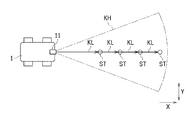
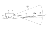
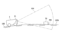
本発明の第1実施形態に係る移動体1は、路面100(被検知物)に対する検知波KLを送波し、路面100からの反射波を受波して、路面100までの検知距離を測定する測距センサ11が設けられた路面検知装置10を備え、路面100を走行する。具体的に、移動体1は、予め設定された経路に沿って移動する四輪の車両であって、測距センサ11、駆動部20、およびCPU30を備えた構成とされている。また、移動体1は、各機能要素に対して電力を供給する部分として充電池などを備えていてもよい。充電池は、例えば、リチウムイオン電池、ニッケル水素電池、Ni−Cd電池、鉛電池、燃料電池、空気電池であって、主として、走行機能、距離検出機能、路面判定機能、通信機能を行うための電力を供給する。
The
駆動部20は、4つの車輪とモータ等の駆動源とによって構成されている。なお、駆動部20は、これに限定されず、車輪の数を変更したり、ベルト等を用いたりしてもよく、移動体1を走行させ、適宜走行する速度を調整できる構成とされていればよい。駆動部20は、走行制御部30eによって、走行する速度や方向が制御される。なお、以下では説明の簡略化のため、移動体1の進行方向Xにおける前方(図1および図2では、右方)を前方と省略することがある。また、上面視において、移動体1の進行方向Xに対して垂直な方向を幅方向Yと呼ぶことがある。
The
測距センサ11は、LIDAR(Light Detection and Ranging)を用いた光学センサであって、検知波KLであるレーザ光を広範囲に照射し、物体からの反射光(反射波)を受光している。それによって、測距センサ11は、路面100および障害物50(後述する図4参照)の位置や距離などを検知している。なお、測距センサ11は、レーザ光に限定されず、赤外線、可視光、超音波、電磁波などを放射して、検知を行ってもよい。
The
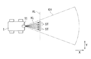
検知波KLは、測距センサ11から進行方向Xの前方に向かって、扇状に広がるように出射されている。つまり、検知波KLが照射された検知範囲KHは、測距センサ11から離れるに従って、高さ方向Zへ広がると伴に、幅方向Yへ広がっている。そして、検知波KLのうち、前方下方へ向かう検知波KLが路面100に照射される。ここで、移動体1は、路面100を障害物50であると誤検知しないように、検知範囲KHに無効領域MRが設定されている。無効領域MR内では、物体の検知結果に拘わらず、障害物50が存在していると判定されない。図1では、検知範囲KH内に一点鎖線を示しており、一点鎖線より下方の領域が無効領域MRに相当する。なお、以下では、無効領域MRと区別するため、無効領域MR以外の検知範囲KHを有効領域と呼ぶことがある。
The detection wave KL is emitted from the
図2に示すように、検知波KLは、送波された方向に対応して測定点STが設定されており、測定点ST毎に、測距センサ11を基準とした検知距離と検知高度とが出力される。具体的に、検知距離は、進行方向Xおよび幅方向Yでの測定点STの位置を示しており、検知高度は、高さ方向Zでの測定点STの位置を示している。図2では、路面100に対応した4つの測定点STが示されているが、これに限定されず、測定点STの数や位置などは、適宜設定すればよい。なお、測定点STは、物体が存在しない位置についても設定されており、この場合、反射波が受波できずに、検知距離として大きな値が出力されるので、物体が無いと判断される。
As shown in FIG. 2, in the detection wave KL, measurement points ST are set corresponding to the transmitted direction. For each measurement point ST, a detection distance and a detection altitude based on the
CPU30は、路面情報生成部30a、路面情報補正部30b、障害物判定部30c、無効領域設定部30d、および走行制御部30eを予め組み込まれたプログラムとして記憶しており、記憶したプログラムを実行することにより、後述する処理を実行する。なお、CPU30は、移動体1と路面検知装置10とで共通に用いられている。また、図3では、省略されているが、移動体1には、測距センサ11の検知結果や、走行速度等の各種設定を記憶させるための記憶装置が設けられていてもよい。
The
路面情報生成部30aは、測距センサ11の測距結果に基づいて、検知波KLが送波された検知範囲KHにおける路面100の状態を示す路面情報を生成する。路面情報補正部30bは、路面情報に基づいて、路面100の傾斜を推定し、路面情報を補正する。障害物判定部30cは、検知範囲KH内に障害物50があるか否かの障害物判定をする。無効領域設定部30dは、路面情報に基づいて、検知範囲KH内で障害物判定が無効とされる無効領域MRを設定する。なお、測距センサ11の測距結果に関する路面情報については、後述する図6ないし図7を参照して、詳細に説明する。
The road surface
図1では、平坦な路面100を検知している状態を示したが、移動体1においては、多様な路面100に対応できることが求められている。以下では、図1と異なる路面の状態について、図面を参照して説明する。
Although FIG. 1 shows a state in which the
図4は、路面上に障害物が存在している状態を示す概略側面図である。 FIG. 4 is a schematic side view showing a state where an obstacle exists on the road surface.
図4は、平坦な路面100上に障害物50が存在している状態を示している。障害物50は、検知範囲KH内(特に、有効領域)に位置しているため、障害物50が有ると判定される。また、路面100については、無効領域MR内に位置しているため、障害物判定が無効とされる。その結果、路面100を誤検知することなく、障害物50までの正確な距離を把握することができる。
FIG. 4 shows a state in which an
図5Aは、路面が上り坂である状態を示す概略側面図である。 FIG. 5A is a schematic side view showing a state where the road surface is an uphill.
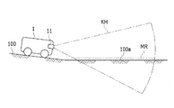
図5Aに示すように、移動体1が平坦な路面100上に位置しているのに対して、移動体1の前方では、路面100が上り坂100aとなっている。ここで、平坦な路面100である場合(例えば、図1)と同様にして、無効領域MRが設定されていると、上り坂100aが無効領域MRよりも上方(有効領域)に位置しているため、路面100(上り坂100a)が障害物50であると誤検知されてしまう。なお、この場合の対処については、後述する図8Aを参照して、詳細に説明する。
As shown in FIG. 5A, the moving
図5Bは、路面が下り坂である状態を示す概略側面図である。 FIG. 5B is a schematic side view showing a state where the road surface is a downhill.
図5Bに示すように、移動体1が平坦な路面100上に位置しているのに対して、移動体1の前方では、路面100が下り坂100bとなっている。また、下り坂100b上には、障害物50が存在している。ここで、平坦な路面100である場合と同様にして、無効領域MRが設定されていると、下り坂100bは、無効領域MRに位置しているため、誤検知されることはない。しかしながら、下り坂100bの上方では、図1と比較すると、広い範囲が無効領域MRとされているため、障害物50も無効領域MR内に含まれ、障害物50の存在が無視されてしまう。なお、この場合の対処については、後述する図8Bを参照して、詳細に説明する。
As shown in FIG. 5B, the moving
上述したように、路面100に傾斜が存在していると、障害物50の検知に不具合が生じることがある。そこで、移動体1では、路面100の傾斜に基づく補正をして、障害物判定をすることで、このような課題を解決している。次に、移動体1での補正方法について、詳細に説明する。
As described above, when the
図6は、本発明の第1実施形態に係る路面検知装置での測定点の配列を示す説明図である。 FIG. 6 is an explanatory diagram showing an array of measurement points in the road surface detection device according to the first embodiment of the present invention.
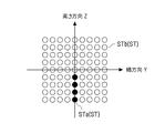
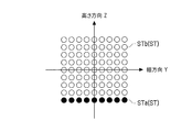
路面検知装置10では、測距センサ11の測距結果に基づいて、検知範囲KHにおける障害物50の有無を示す検知画像を生成しており、検知範囲KHにおける障害物50の有無と、障害物50の位置とを関連付けている。本実施の形態において、検知画像は、移動体1の進行方向Xに対し直交する平面に対応しており、矩形状とされている。つまり、検知画像では、それぞれの座標(画素)に対応する測定点STがマトリクス条に配列されている。図6では、横軸が幅方向Yに対応し、縦軸が高さ方向Zに対応している。横軸と縦軸とが交差する原点は、移動体1の正面に対応している。原点に対し、横軸の負の方向へ進むに従って、移動体1の左方に位置しており、横軸の正の方向へ進むに従って、移動体1の右方に位置している。また、原点に対し、縦軸の負の方向へ進むに従って、移動体1の下方に位置しており、縦軸の正の方向へ進むに従って、移動体1の上方に位置している。
The road
路面情報生成部30aは、図6に示す検知画像に基づいて、測定点ST毎の検知高度が配列された路面情報を生成する。ここで、路面情報生成部30aは、予め決められた走査方向に沿って、検知画像から路面情報を生成するための測定点STを抽出する。つまり、測定点STは、路面情報生成部30aに抽出された抽出測定点STaと、それ以外の未抽出測定点STbとに分けられる。本実施の形態において、走査方向は、進行方向Xと一致しており、縦軸に沿って、原点から下方の測定点STが抽出測定点STaとされている。具体的に、抽出測定点STaは、図2に示すように、上面視において、進行方向Xに沿って並んでいる。つまり、移動体1に対し、進行方向Xで異なる距離の測定点STにおける検知高度を比較することで、移動体1の前方における路面100の傾斜を検知している。
The road surface
図7は、路面情報の一例を示す説明図である。 FIG. 7 is an explanatory diagram illustrating an example of road surface information.
図7は、路面情報生成部30aに生成された路面情報の一例を示しており、図5Aのように、移動体1の前方で路面100が上り坂100aとなっている場合に対応している。図7では、横軸は、移動体1からの距離を示しており、縦軸は、移動体1に対する高度を示している。なお、高度については、移動体1を基準として予め設定された位置を原点とすればよく、路面100と原点とを一致させる必要はない。また、図7に示す一点鎖線は、無効領域MRを示しており、無効領域MR以下の値については、障害物判定を無効とする。
FIG. 7 shows an example of the road surface information generated by the road surface
図7では、4つの抽出測定点STaが、それぞれの検知距離DLおよび検知高度DHに対応する座標に位置している。図7に示す4つの抽出測定点STaは、距離が大きくなるに従って、高度が大きくなるように並んでいる。路面情報補正部30bは、抽出測定点STaの検知距離DLおよび検知高度DHに基づいて、傾斜直線SLを算出する。具体的に、傾斜直線SLは、抽出測定点STaに基づいて算出された近似直線であって、本実施の形態では、最小二乗法を用いている。なお、図面の見易さを考慮して、抽出測定点STaを4つとしているが、これに限定されず、抽出測定点STaの数を増やすことで、傾斜直線SLを精度よく算出することができる。また、傾斜直線SLの算出方法は、最小二乗法に限定されず、他の直線回帰方法を用いてもよい。さらに、検知距離DLまたは検知高度DHが極端に異なった外れ値については、外れ値を除去して傾斜直線SLを算出するようにしてもよい。
In FIG. 7, four extraction measurement points STa are located at coordinates corresponding to the detection distance DL and the detection height DH. The four extraction measurement points STa shown in FIG. 7 are arranged so that the altitude increases as the distance increases. The road surface
路面情報補正部30bは、傾斜直線SLを算出した後、傾斜直線SLを補正直線HLのように平坦にする。補正直線HLは、横軸に対して平行とされている。つまり、抽出測定点STaは、補正直線HLに応じた高度とされ、補正直線HLに沿った補正測定点HTに補正される。補正された補正測定点HTは、無効領域MRより低い値となっている。上述したように、路面情報補正部30bは、抽出測定点STaに基づく路面情報を、補正測定点HTに基づく路面情報へ補正する。
After calculating the inclined straight line SL, the road surface
図8Aは、図5Aの補正後の検知範囲を示す説明図である。 FIG. 8A is an explanatory diagram illustrating the detection range after correction in FIG. 5A.
図8Aは、図5Aに対し、路面情報補正部30bによって路面情報を補正した状態である。無効領域設定部30dは、補正後の路面情報に基づき、上り坂100aの傾斜に沿って無効領域MRを設定している。なお、図8Aは、図5A全体を回転させた状態であって、路面100の傾斜や移動体1の位置は変化していない。つまり、移動体1は、自身の向きに拘わらず、見かけ上、前方の上り坂100aが平坦になるように補正する。その結果、上り坂100aは、無効領域MR内に収まり、誤検知を防止することができる。
FIG. 8A shows a state in which the road surface information is corrected by the road surface
図8Bは、図5Bの補正後の検知範囲を示す説明図である。 FIG. 8B is an explanatory diagram illustrating the detection range after correction in FIG. 5B.
図8Bは、図5Bに対し、路面情報補正部30bによって路面情報を補正した状態である。無効領域設定部30dは、補正後の路面情報に基づき、下り坂100bの傾斜に沿って無効領域MRを設定している。なお、図8Bは、図5B全体を回転させた状態であって、路面100の傾斜や移動体1の位置は変化していない。つまり、図8Aと同様に、移動体1は、自身の向きに拘わらず、見かけ上、前方の下り坂100bが平坦になるように補正する。その結果、下り坂100bに沿って無効領域MRが設定され、障害物50の見落としを防ぐことができる。
FIG. 8B is a state in which the road surface information is corrected by the road surface
本実施の形態は、移動体1が傾斜のある路面100に位置している場合でも適用することができる。例えば、図8Aに示す場合では、移動体1が下り坂に位置しており、前方が平坦な路面であるとみなすことができる。この場合、測距センサ11が下方に向いており、測距センサ11の向きに沿って無効領域MRを設定すると、誤検知を生じる虞があるため、路面情報を補正することで、適切な無効領域MRを設定することができる。また、図8Bに示す場合では、移動体1が上り坂に位置しており、前方が平坦な路面であるとみなすことができる。この場合でも、同様にして、路面情報を補正する。
The present embodiment can be applied even when the moving
次に、路面検知装置10(移動体1)における路面検知方法の処理フローについて、図面を参照して説明する。 Next, a processing flow of the road surface detection method in the road surface detection device 10 (moving body 1) will be described with reference to the drawings.
図9は、本発明の第1実施形態に係る路面検知装置の路面検知方法の処理フローを示すフロー図である。 FIG. 9 is a flowchart showing a processing flow of the road surface detection method of the road surface detection device according to the first embodiment of the present invention.
ステップS01では、路面情報生成部30aによって、路面情報を生成する。つまり、測距センサ11が出力した検知距離DLおよび検知高度DHから路面情報を生成する。
In step S01, road surface information is generated by the road surface
ステップS02では、路面情報補正部30bによって、傾斜直線SLを算出する(例えば、図7参照)。
In step S02, the road surface
ステップS03では、路面情報補正部30bによって、路面情報を補正する。なお、傾斜直線SLが平坦である場合には、補正しなくてもよい。
In step S03, the road surface information is corrected by the road surface
ステップS04では、無効領域設定部30dによって、無効領域MRを設定する。無効領域MRは、例えば、補正直線HLと平行に設定すればよい。
In step S04, the invalid area MR is set by the invalid
ステップS05では、障害物判定部30cによって、障害物判定をした後、処理を終了する。つまり、有効領域に障害物50(測定点ST)があるか否かによって、障害物50の有無を判定する。
In step S05, the
移動体1は、上述した処理フローを繰り返しており、例えば、時間の経過や移動した距離に応じて、随時、ステップS01ないしステップS05に示す処理を行う。
The moving
本発明に係る路面検知方法は、路面100に対する検知波KLを送波し、路面100からの反射波を受波して、路面100までの検知距離DLを測定する測距センサ11を備えた路面検知装置10における路面検知方法であって、路面情報生成部30aに、測距センサ11の測距結果に基づいて、検知波KLが送波された検知範囲KHにおける路面100の状態を示す路面情報を生成させる路面情報生成ステップと、路面情報補正部30bに、路面情報に基づいて、路面100の傾斜を推定し、路面情報を補正させる路面情報補正ステップと、障害物判定部30cに、検知範囲KH内に障害物50があるか否かの障害物判定をさせる障害物判定ステップと、無効領域設定部30dに、路面情報に基づいて、検知範囲KH内で障害物判定が無効とされる無効領域MRを設定させる無効領域設定ステップとを含んでいる。
The road surface detection method according to the present invention includes a
従って、路面100の傾斜を推定することで、検知範囲KH内での路面100の傾斜を把握することができる。また、路面情報を補正することで、傾斜のある路面100を平面のようにみなすことができる。それによって、傾いた路面100を障害物50であると誤検知したり、路面100上の広い範囲を無効領域MRとして障害物50を見落としたりすることを防止できる。
Therefore, by estimating the inclination of the
路面情報は、予め決められた走査方向に沿って並んだ複数の測定点STが設定されている。測距センサ11は、測定点ST毎に、測距センサ11を基準とした検知高度DHを出力する構成とされている。路面情報補正ステップは、走査方向に沿った検知高度DHの推移から、路面100の傾斜を推定する。
In the road surface information, a plurality of measurement points ST arranged along a predetermined scanning direction are set. The
測距センサ11は、上面視(例えば、図2参照)において、測距センサ11が設けられた位置から離間した路面100に向かって検知波KLを照射している。走査方向は、上面視において、検知波KLの照射方向(進行方向X)と一致している。従って、測距センサ11から離間した位置での、照射方向に沿った路面100の傾斜を推定することができる。つまり、移動体1の進行方向Xに沿った路面100の傾斜を補正することができる。
The
路面情報補正部30bは、測定点ST毎の検知距離DLおよび検知高度DHに基づいて、傾斜直線SLを算出し、傾斜直線SLを用いて、測定点ST毎に高度を補正する。従って、傾斜直線SLを算出することで、測距の際の小さな誤差を緩和し、広い範囲での路面100の傾斜を把握することができる。
The road surface
(第2実施形態)
次に、本発明の第2実施形態に係る路面検知装置および移動体について、図面を参照して説明する。なお、第2実施形態は、第1実施形態に対して、略同様の形状とされているので、外観図や構成図を省略し、第1実施形態と機能が実質的に等しい構成要素については、同一の符号を付して説明を省略する。
(Second Embodiment)
Next, a road surface detection apparatus and a moving body according to a second embodiment of the present invention will be described with reference to the drawings. Since the second embodiment has substantially the same shape as the first embodiment, the external view and the configuration diagram are omitted, and the components having substantially the same functions as those of the first embodiment are omitted. The same reference numerals are given and the description is omitted.
図10は、移動体が傾斜した路面に位置している状態を示す概略正面図である。 FIG. 10 is a schematic front view showing a state where the moving body is located on an inclined road surface.
図10は、移動体1を前方から見た状態を示しており、移動体1は、幅方向Yに対して傾斜した勾配面100cに位置しており、移動体1の前方の路面は、水平な水平面100dである。第1実施形態は、進行方向Xに沿った傾斜を推定していたのに対して、第2実施形態は、幅方向Yに沿った傾斜を推定している。図10に示す状態では、勾配面100cに位置している測距センサ11が幅方向Yで、水平面100dに対して傾斜しているため、水平面100dは、左方と右方とで異なる検知高度DHが出力される。そこで、幅方向Yでの補正方法を以下に説明する。
FIG. 10 shows a state in which the moving
図11は、図10に示す移動体の概略上面図であって、図12は、本発明の第2実施形態に係る路面検知装置での測定点の配列を示す説明図である。 FIG. 11 is a schematic top view of the moving body shown in FIG. 10, and FIG. 12 is an explanatory diagram showing an array of measurement points in the road surface detection device according to the second embodiment of the present invention.
第2実施形態では、図11のように、幅方向Yに平行な補助線ALに沿って、複数の測定点STが設定され、これらを抽出測定点STaとしている。つまり、図12に示す検知画像では、高さ方向Zで最も下方の測定点STが抽出測定点STaとされている。なお、抽出する測定点STは、これに限定されず、高さ方向Zでの座標を一定として、幅方向Yに沿った測定点STを複数抽出すればよい。 In the second embodiment, as shown in FIG. 11, a plurality of measurement points ST are set along the auxiliary line AL parallel to the width direction Y, and these are set as the extraction measurement points STa. That is, in the detection image shown in FIG. 12, the lowest measurement point ST in the height direction Z is set as the extraction measurement point STa. Note that the measurement points ST to be extracted are not limited to this, and a plurality of measurement points ST along the width direction Y may be extracted with the coordinates in the height direction Z being constant.
図13は、路面情報の一例を示す説明図である。 FIG. 13 is an explanatory diagram illustrating an example of road surface information.
図13は、路面情報生成部30aに生成された路面情報の一例を示しており、移動体1の前方の路面100が幅方向Yに対して傾斜している場合を示している。図13では、横軸は、移動体1の正面を原点として、幅方向Yでの距離を示しており、縦軸は、移動体1に対する高度を示している。つまり、原点に対し、横軸の負の方向へ進むに従って、移動体1の左方に位置しており、横軸の正の方向へ進むに従って、移動体1の右方に位置している。
FIG. 13 shows an example of the road surface information generated by the road surface
図13に示す5つの抽出測定点STaは、幅方向Yで正の方向に向かうに従って、高度が大きくなるように並んでおり、移動体1の右方の抽出測定点STaは、検知高度DHが無効領域MRより大きい値となっている。
The five extraction measurement points STa shown in FIG. 13 are arranged such that the height increases in the width direction Y in the positive direction. The extraction measurement point STa on the right side of the
本実施形態では、上述した図7のように、抽出測定点STaの検知距離DLおよび検知高度DHに基づいて、傾斜直線SLを算出する。そして、路面情報補正部30bは、傾斜直線SLを算出した後、傾斜直線SLを補正直線HLのように平坦にすることで、抽出測定点STaに基づく路面情報を、補正測定点HTに基づく路面情報へ補正する。これによって、移動体1の幅方向Yに沿った路面100の傾斜を補正することができる。
In the present embodiment, as shown in FIG. 7 described above, the inclined straight line SL is calculated based on the detection distance DL and the detection height DH of the extraction measurement point STa. Then, the road surface
第2実施形態では、第1実施形態と同様の処理フローを実施すればよく、幅方向Yでの傾斜直線SL(図13参照)に基づいて補正すればよい。 In the second embodiment, the same processing flow as in the first embodiment may be performed, and correction may be performed based on the inclined straight line SL (see FIG. 13) in the width direction Y.
(第3実施形態)
次に、本発明の第3実施形態に係る路面検知装置および移動体について説明する。なお、第3実施形態は、第1実施形態および第2実施形態に対して、略同様の形状とされているので、図面を省略し、第1実施形態および第2実施形態と機能が実質的に等しい構成要素については、同一の符号を付して説明を省略する。
(Third embodiment)
Next, a road surface detection apparatus and a moving body according to a third embodiment of the present invention will be described. Since the third embodiment has substantially the same shape as the first embodiment and the second embodiment, the drawings are omitted, and the functions are substantially the same as those of the first embodiment and the second embodiment. Constituent elements equal to are denoted by the same reference numerals and description thereof is omitted.
第1実施形態および第2実施形態では、進行方向Xまたは幅方向Yのうち、一方に沿った傾斜を補正していたのに対して、第3実施形態では、進行方向Xおよび幅方向Yの両方に沿った傾斜を補正している。具体的に、路面情報は、2つの走査方向に沿ってそれぞれ並んだ複数の測定点STが設定されている。2つの走査方向のうち、一方は、上面視において、検知波KLの照射方向と一致(進行方向X)しており、他方は、上面視において、検知波KLの照射方向と直交(幅方向Y)している。すなわち、本実施の形態では、進行方向Xに沿った傾斜直線SL(図7参照)と、幅方向Yに沿った傾斜直線SL(図13参照)とを算出しており、2つの傾斜直線SLを用いて、測定点STの高度を補正している。従って、2つの走査方向に沿った測定点STを設定することで、様々な方向に傾いた路面100に対応することができる。
In the first and second embodiments, the inclination along one of the traveling direction X and the width direction Y is corrected, whereas in the third embodiment, the traveling direction X and the width direction Y are corrected. The inclination along both is corrected. Specifically, as the road surface information, a plurality of measurement points ST arranged in two scanning directions are set. One of the two scanning directions coincides with the irradiation direction of the detection wave KL when viewed from above (traveling direction X), and the other is perpendicular to the irradiation direction of the detection wave KL when viewed from above (width direction Y). )doing. That is, in the present embodiment, an inclined straight line SL (see FIG. 7) along the traveling direction X and an inclined straight line SL (see FIG. 13) along the width direction Y are calculated, and two inclined straight lines SL are calculated. Is used to correct the altitude of the measurement point ST. Therefore, by setting the measurement points ST along the two scanning directions, it is possible to deal with the
(第4実施形態)
次に、本発明の第4実施形態に係る路面検知装置および移動体について、図面を参照して説明する。なお、第4実施形態は、第1実施形態ないし第3実施形態に対して、略同様の形状とされているので、外観図や構成図を省略し、第1実施形態ないし第3実施形態と機能が実質的に等しい構成要素については、同一の符号を付して説明を省略する。
(Fourth embodiment)
Next, a road surface detection apparatus and a moving body according to a fourth embodiment of the present invention will be described with reference to the drawings. Since the fourth embodiment has substantially the same shape as the first to third embodiments, the external view and the configuration diagram are omitted, and the fourth embodiment is the same as the first to third embodiments. Constituent elements having substantially the same functions are denoted by the same reference numerals and description thereof is omitted.
図14は、路面が上り坂であって、障害物が存在している状態を示す概略側面図であって、図15Aは、路面情報から算出された仮想傾斜直線を示す説明図である。 FIG. 14 is a schematic side view showing a state where the road surface is uphill and an obstacle is present, and FIG. 15A is an explanatory diagram showing a virtual inclination straight line calculated from road surface information.
図14では、移動体1の前方が上り坂100aであって、上り坂100aには、障害物50が存在している。以下では説明のため、移動体1から障害物50までの距離を障害物距離DLaと呼ぶことがある。
In FIG. 14, the front side of the moving
抽出測定点STaは、前方が上り坂100aであるため、検知距離DLが大きくなるに従って、検知高度DHが大きくなるように並んでいる。ところで、図14に示すように、検知波KLは、障害物距離DLaにおいて、障害物50に反射されるため、横軸の座標が障害物距離DLaであって、高度(縦軸の座標)の異なる抽出測定点STaが複数出力される。障害物距離DLaまでの抽出測定点STaと、横軸の座標が同じで高度の異なる抽出測定点STaとを併せて算出された仮想傾斜直線KSLは、障害物距離DLaまでの傾斜よりも上方へ傾いた直線となる。つまり、全ての抽出測定点STaを採用すると、障害物50も含めて傾斜が算出されるため、実際の路面100とは異なる傾斜であると推定されてしまう。そこで、第4実施形態は、検知範囲KH内に障害物50が存在する場合などに、測定点STを選別して、傾斜直線SLの算出方法を異ならせている。
Since the extraction measurement points STa are uphill 100a ahead, they are arranged such that the detection height DH increases as the detection distance DL increases. By the way, as shown in FIG. 14, since the detection wave KL is reflected by the
図15Bは、路面情報から算出された傾斜直線を示す説明図である。 FIG. 15B is an explanatory diagram illustrating an inclined straight line calculated from road surface information.
路面情報補正部30bは、走査方向での位置が同じ測定点STが複数存在する場合、検知高度DHが最も低い測定点STを路面情報の補正に用いる。具体的には、障害物距離DLaに位置する抽出測定点STaのうち、検知高度DHが最も低い抽出測定点STaを採用測定点STa1とし、残りを非採用測定点STa2とする。その結果、障害物距離DLaまでの抽出測定点STaと、採用測定点STa1とに基づいて、傾斜直線SLが算出される。つまり、傾斜直線SLを算出する際には、採用測定点STa1が用いられ、非採用測定点STa2が無視される。従って、検知範囲KH内に障害物50が存在する場合などで、路面100の高度とのズレが生じるため、適切な測定点STだけを採用することで、正確に路面100の傾斜を推定することができる。
When there are a plurality of measurement points ST having the same position in the scanning direction, the road surface
本実施の形態では、進行方向Xに沿った傾斜について説明したが、これに限定されず、幅方向Yでの傾斜を算出する際にも、測定点STを選別してもよい。つまり、幅方向Yでの位置が同じで、検知高度DHが異なる抽出測定点STaが複数存在する場合も同様に、検知高度DHが最も低い抽出測定点STaを採用測定点STa1とすればよい。 In the present embodiment, the inclination along the traveling direction X has been described. However, the present invention is not limited to this, and the measurement point ST may be selected when calculating the inclination in the width direction Y. That is, when there are a plurality of extraction measurement points STa having the same position in the width direction Y but different in detection height DH, similarly, the extraction measurement point STa having the lowest detection height DH may be set as the adopted measurement point STa1.
なお、今回開示した実施の形態は全ての点で例示であって、限定的な解釈の根拠となるものではない。従って、本発明の技術的範囲は、上記した実施の形態のみによって解釈されるものではなく、特許請求の範囲の記載に基づいて画定される。また、特許請求の範囲と均等の意味および範囲内での全ての変更が含まれる。 It should be noted that the embodiment disclosed herein is illustrative in all respects and does not serve as a basis for limited interpretation. Therefore, the technical scope of the present invention is not interpreted only by the above-described embodiment, but is defined based on the description of the scope of claims. Moreover, all the changes within the meaning and range equivalent to a claim are included.
1 移動体
10 路面検知装置
11 測距センサ
20 駆動部
30 CPU
30a 路面情報生成部
30b 路面情報補正部
30c 障害物判定部
30d 無効領域設定部
30e 走行制御部
50 障害物
100 路面
KH 検知範囲
X 進行方向
Y 幅方向
Z 高さ方向
DESCRIPTION OF
30a Road surface
Claims (10)
前記測距センサの測距結果に基づいて、前記検知波が送波された検知範囲における路面の状態を示す路面情報を生成する路面情報生成部と、
前記路面情報に基づいて、前記路面の傾斜を推定し、該路面情報を補正する路面情報補正部と、
前記検知範囲内に障害物があるか否かの障害物判定をする障害物判定部と、
前記路面情報に基づいて、前記検知範囲内で前記障害物判定が無効とされる無効領域を設定する無効領域設定部とを備えていること
を特徴とする路面検知装置。 A ranging sensor that transmits a detection wave to the object to be detected, receives a reflected wave from the object to be detected, and measures a detection distance to the object to be detected;
A road surface information generating unit that generates road surface information indicating a road surface state in a detection range in which the detection wave is transmitted based on a distance measurement result of the distance sensor;
Based on the road surface information, a road surface information correction unit that estimates the slope of the road surface and corrects the road surface information;
An obstacle determination unit for determining whether there is an obstacle within the detection range; and
A road surface detection device comprising: an invalid area setting unit configured to set an invalid area in which the obstacle determination is invalid within the detection range based on the road surface information.
前記路面情報は、予め決められた走査方向に沿って並んだ複数の測定点が設定され、
前記測距センサは、前記測定点毎に、該測距センサを基準とした検知高度を出力する構成とされ、
前記路面情報補正部は、前記走査方向に沿った前記検知高度の推移から、前記路面の傾斜を推定すること
を特徴とする路面検知装置。 The road surface detection device according to claim 1,
In the road surface information, a plurality of measurement points arranged along a predetermined scanning direction are set.
The distance measuring sensor is configured to output a detection altitude based on the distance measuring sensor for each measurement point,
The road surface information correction unit estimates the inclination of the road surface from the transition of the detected height along the scanning direction.
前記測距センサは、上面視において、該測距センサが設けられた位置から離間した路面に向かって前記検知波を照射しており、
前記走査方向は、上面視において、前記検知波の照射方向と一致していること
を特徴とする路面検知装置。 The road surface detection device according to claim 2,
The distance measuring sensor irradiates the detection wave toward a road surface separated from a position where the distance measuring sensor is provided in a top view;
The road surface detection device characterized in that the scanning direction coincides with the irradiation direction of the detection wave in a top view.
前記測距センサは、上面視において、該測距センサが設けられた位置から離間した路面に向かって前記検知波を照射しており、
前記走査方向は、上面視において、前記検知波の照射方向と直交していること
を特徴とする路面検知装置。 The road surface detection device according to claim 2,
The distance measuring sensor irradiates the detection wave toward a road surface separated from a position where the distance measuring sensor is provided in a top view;
The scanning direction is orthogonal to the irradiation direction of the detection wave in a top view.
前記路面情報は、2つの走査方向に沿ってそれぞれ並んだ複数の測定点が設定され、
前記2つの走査方向のうち、一方は、上面視において、前記検知波の照射方向と一致しており、他方は、上面視において、前記検知波の照射方向と直交していること
を特徴とする路面検知装置。 The road surface detection device according to claim 3 or 4,
The road surface information is set with a plurality of measurement points arranged along two scanning directions,
One of the two scanning directions is coincident with the irradiation direction of the detection wave in a top view, and the other is orthogonal to the irradiation direction of the detection wave in a top view. Road surface detection device.
前記路面情報補正部は、前記走査方向での位置が同じ測定点が複数存在する場合、前記検知高度が最も低い測定点を前記路面情報の補正に用いること
を特徴とする路面検知装置。 The road surface detection device according to any one of claims 2 to 5,
The road surface information correcting unit, when there are a plurality of measurement points having the same position in the scanning direction, uses the measurement point with the lowest detected altitude for correcting the road surface information.
前記路面情報補正部は、前記測定点毎の検知距離および検知高度に基づいて、傾斜直線を算出し、前記傾斜直線を用いて、該測定点毎に高度を補正すること
を特徴とする路面検知装置。 The road surface detection device according to any one of claims 2 to 6,
The road surface information correction unit calculates an inclined straight line based on a detection distance and a detected altitude for each measurement point, and uses the inclined straight line to correct the altitude for each measurement point. apparatus.
路面情報生成部に、前記測距センサの測距結果に基づいて、前記検知波が送波された検知範囲における路面の状態を示す路面情報を生成させる路面情報生成ステップと、
路面情報補正部に、前記路面情報に基づいて、前記路面の傾斜を推定し、該路面情報を補正させる路面情報補正ステップと、
障害物判定部に、前記検知範囲内に障害物があるか否かの障害物判定をさせる障害物判定ステップと、
無効領域設定部に、前記路面情報に基づいて、前記検知範囲内で前記障害物判定が無効とされる無効領域を設定させる無効領域設定ステップとを含むこと
を特徴とする路面検知方法。 A road surface detection method in a road surface detection device including a distance measuring sensor that transmits a detection wave to a detection object, receives a reflected wave from the detection object, and measures a detection distance to the detection object. There,
A road surface information generation step for generating road surface information indicating a road surface state in a detection range where the detection wave is transmitted based on a distance measurement result of the distance sensor,
A road surface information correcting step for estimating an inclination of the road surface based on the road surface information and correcting the road surface information;
An obstacle determination step for causing the obstacle determination unit to determine whether there is an obstacle within the detection range; and
An invalid area setting step of causing an invalid area setting unit to set an invalid area in which the obstacle determination is invalid within the detection range based on the road surface information.
Priority Applications (1)
| Application Number | Priority Date | Filing Date | Title |
|---|---|---|---|
| JP2015129097A JP2017015409A (en) | 2015-06-26 | 2015-06-26 | Road surface detection device, mobile body, road surface detection method, and road surface detection program |
Applications Claiming Priority (1)
| Application Number | Priority Date | Filing Date | Title |
|---|---|---|---|
| JP2015129097A JP2017015409A (en) | 2015-06-26 | 2015-06-26 | Road surface detection device, mobile body, road surface detection method, and road surface detection program |
Publications (1)
| Publication Number | Publication Date |
|---|---|
| JP2017015409A true JP2017015409A (en) | 2017-01-19 |
Family
ID=57827727
Family Applications (1)
| Application Number | Title | Priority Date | Filing Date |
|---|---|---|---|
| JP2015129097A Pending JP2017015409A (en) | 2015-06-26 | 2015-06-26 | Road surface detection device, mobile body, road surface detection method, and road surface detection program |
Country Status (1)
| Country | Link |
|---|---|
| JP (1) | JP2017015409A (en) |
Cited By (12)
| Publication number | Priority date | Publication date | Assignee | Title |
|---|---|---|---|---|
| JP2018132376A (en) * | 2017-02-14 | 2018-08-23 | 日立建機株式会社 | Delivery vehicle and road surface estimation method |
| WO2018164203A1 (en) * | 2017-03-10 | 2018-09-13 | 日立建機株式会社 | Scanner, working machine, and wheel stopper detecting device |
| WO2019163005A1 (en) * | 2018-02-20 | 2019-08-29 | 三菱電機株式会社 | Measurement monitoring apparatus and measurement monitoring program |
| JP2019168290A (en) * | 2018-03-22 | 2019-10-03 | パナソニックIpマネジメント株式会社 | Radar device, position estimation device, and position estimation method |
| WO2019188015A1 (en) * | 2018-03-30 | 2019-10-03 | 日立建機株式会社 | Working machine reversing support device |
| JP6625267B1 (en) * | 2018-06-22 | 2019-12-25 | 三菱電機株式会社 | Sensor control device, vehicle, sensing method, and sensor control program |
| JP2020051971A (en) * | 2018-09-28 | 2020-04-02 | 三菱電機株式会社 | Laser distance measuring device |
| JP2020068897A (en) * | 2018-10-29 | 2020-05-07 | 大成建設株式会社 | Cleaning robot |
| JPWO2018180104A1 (en) * | 2017-03-31 | 2020-05-14 | パイオニア株式会社 | Judgment device, judgment method, judgment program, and data structure |
| WO2020170745A1 (en) * | 2019-02-21 | 2020-08-27 | 日立オートモティブシステムズ株式会社 | Traveling road recognition device |
| WO2022190324A1 (en) * | 2021-03-11 | 2022-09-15 | 株式会社Fuji | Moving system and management device |
| WO2023127557A1 (en) * | 2021-12-27 | 2023-07-06 | 株式会社クボタ | Agricultural machine, sensing system used in agricultural machine, and sensing method |
-
2015
- 2015-06-26 JP JP2015129097A patent/JP2017015409A/en active Pending
Cited By (21)
| Publication number | Priority date | Publication date | Assignee | Title |
|---|---|---|---|---|
| JP2018132376A (en) * | 2017-02-14 | 2018-08-23 | 日立建機株式会社 | Delivery vehicle and road surface estimation method |
| WO2018164203A1 (en) * | 2017-03-10 | 2018-09-13 | 日立建機株式会社 | Scanner, working machine, and wheel stopper detecting device |
| JPWO2018180104A1 (en) * | 2017-03-31 | 2020-05-14 | パイオニア株式会社 | Judgment device, judgment method, judgment program, and data structure |
| JP7174131B2 (en) | 2017-03-31 | 2022-11-17 | パイオニア株式会社 | Determination device, determination method and determination program |
| JP2022009231A (en) * | 2017-03-31 | 2022-01-14 | パイオニア株式会社 | Determination device, determination method, and determination program |
| WO2019163005A1 (en) * | 2018-02-20 | 2019-08-29 | 三菱電機株式会社 | Measurement monitoring apparatus and measurement monitoring program |
| JPWO2019163005A1 (en) * | 2018-02-20 | 2020-10-22 | 三菱電機株式会社 | Measurement monitoring device and measurement monitoring program |
| JP2019168290A (en) * | 2018-03-22 | 2019-10-03 | パナソニックIpマネジメント株式会社 | Radar device, position estimation device, and position estimation method |
| JP2019178972A (en) * | 2018-03-30 | 2019-10-17 | 日立建機株式会社 | Retreat support device of operating machine |
| WO2019188015A1 (en) * | 2018-03-30 | 2019-10-03 | 日立建機株式会社 | Working machine reversing support device |
| JP6625267B1 (en) * | 2018-06-22 | 2019-12-25 | 三菱電機株式会社 | Sensor control device, vehicle, sensing method, and sensor control program |
| JP2020051971A (en) * | 2018-09-28 | 2020-04-02 | 三菱電機株式会社 | Laser distance measuring device |
| US10935662B2 (en) | 2018-09-28 | 2021-03-02 | Mitsubishi Electric Cornoration | Laser distance measuring apparatus |
| JP2020068897A (en) * | 2018-10-29 | 2020-05-07 | 大成建設株式会社 | Cleaning robot |
| WO2020170745A1 (en) * | 2019-02-21 | 2020-08-27 | 日立オートモティブシステムズ株式会社 | Traveling road recognition device |
| JP2020134367A (en) * | 2019-02-21 | 2020-08-31 | 日立オートモティブシステムズ株式会社 | Travel road recognition device |
| CN113424240A (en) * | 2019-02-21 | 2021-09-21 | 日立安斯泰莫株式会社 | Travel road recognition device |
| JP7257814B2 (en) | 2019-02-21 | 2023-04-14 | 日立Astemo株式会社 | Driving path recognition device |
| CN113424240B (en) * | 2019-02-21 | 2023-11-17 | 日立安斯泰莫株式会社 | Road identification device |
| WO2022190324A1 (en) * | 2021-03-11 | 2022-09-15 | 株式会社Fuji | Moving system and management device |
| WO2023127557A1 (en) * | 2021-12-27 | 2023-07-06 | 株式会社クボタ | Agricultural machine, sensing system used in agricultural machine, and sensing method |
Similar Documents
| Publication | Publication Date | Title |
|---|---|---|
| JP2017015409A (en) | Road surface detection device, mobile body, road surface detection method, and road surface detection program | |
| JP2017015601A (en) | Road surface detection device, mobile body, road surface detection method, and road surface detection program | |
| KR101900228B1 (en) | Method and apparatus for parking assistance | |
| JP6756124B2 (en) | Object detection device and object detection program | |
| US10260889B2 (en) | Position estimation device and position estimation method | |
| US9348017B2 (en) | Method and device for ascertaining a misalignment of a radar sensor of a vehicle | |
| US10692229B2 (en) | Recess detection device, transport device, and recess detecting method | |
| US20180370566A1 (en) | Parking Support Method and Device | |
| WO2021189468A1 (en) | Attitude correction method, apparatus and system for laser radar | |
| US20120099798A1 (en) | Information processing apparatus, information processing method, and program | |
| WO2012133457A1 (en) | Object recognition device | |
| JP2017506382A (en) | Method and control device for detecting relative yaw angle changes in a vehicle stereo / video system | |
| CN109444916A (en) | The unmanned travelable area determining device of one kind and method | |
| JP2011196699A (en) | Device for detecting road edge | |
| JP2023115057A (en) | Measurement device, method for measurement, and program | |
| JP2020135619A (en) | Unmanned conveyance system and self-position estimation method for unmanned conveyance vehicle | |
| JP5851715B2 (en) | Autonomous traveling device, autonomous traveling method, and program thereof | |
| CN108292441A (en) | The method of vision system and control vision system for motor vehicles | |
| JP2020148470A (en) | Road surface detector | |
| JP2010250743A (en) | Automatic running vehicle and road shape recognition system | |
| CN106682584B (en) | Unmanned aerial vehicle obstacle detection method and device | |
| CN110109146B (en) | Road surface detection method and device based on multi-line laser radar | |
| JP2008298741A (en) | Distance measuring apparatus and distance measuring method | |
| CN110109145B (en) | Driving area detection method and device based on multi-line laser radar | |
| JP2015007639A (en) | Information processing apparatus, information processing method and program |