JP2017013231A - drill - Google Patents
drill Download PDFInfo
- Publication number
- JP2017013231A JP2017013231A JP2016203828A JP2016203828A JP2017013231A JP 2017013231 A JP2017013231 A JP 2017013231A JP 2016203828 A JP2016203828 A JP 2016203828A JP 2016203828 A JP2016203828 A JP 2016203828A JP 2017013231 A JP2017013231 A JP 2017013231A
- Authority
- JP
- Japan
- Prior art keywords
- drill
- margin
- rotation axis
- thinning
- boundary
- Prior art date
- Legal status (The legal status is an assumption and is not a legal conclusion. Google has not performed a legal analysis and makes no representation as to the accuracy of the status listed.)
- Granted
Links
Images


Classifications
-
- B—PERFORMING OPERATIONS; TRANSPORTING
- B23—MACHINE TOOLS; METAL-WORKING NOT OTHERWISE PROVIDED FOR
- B23B—TURNING; BORING
- B23B51/00—Tools for drilling machines
- B23B51/02—Twist drills
-
- B—PERFORMING OPERATIONS; TRANSPORTING
- B23—MACHINE TOOLS; METAL-WORKING NOT OTHERWISE PROVIDED FOR
- B23B—TURNING; BORING
- B23B51/00—Tools for drilling machines
- B23B51/06—Drills with lubricating or cooling equipment
-
- B—PERFORMING OPERATIONS; TRANSPORTING
- B23—MACHINE TOOLS; METAL-WORKING NOT OTHERWISE PROVIDED FOR
- B23B—TURNING; BORING
- B23B2251/00—Details of tools for drilling machines
- B23B2251/04—Angles, e.g. cutting angles
-
- B—PERFORMING OPERATIONS; TRANSPORTING
- B23—MACHINE TOOLS; METAL-WORKING NOT OTHERWISE PROVIDED FOR
- B23B—TURNING; BORING
- B23B2251/00—Details of tools for drilling machines
- B23B2251/08—Side or plan views of cutting edges
- B23B2251/082—Curved cutting edges
-
- B—PERFORMING OPERATIONS; TRANSPORTING
- B23—MACHINE TOOLS; METAL-WORKING NOT OTHERWISE PROVIDED FOR
- B23B—TURNING; BORING
- B23B2251/00—Details of tools for drilling machines
- B23B2251/12—Cross sectional views of the cutting edges
- B23B2251/125—Rounded cutting edges
-
- B—PERFORMING OPERATIONS; TRANSPORTING
- B23—MACHINE TOOLS; METAL-WORKING NOT OTHERWISE PROVIDED FOR
- B23B—TURNING; BORING
- B23B2251/00—Details of tools for drilling machines
- B23B2251/12—Cross sectional views of the cutting edges
- B23B2251/127—Sharp cutting edges
-
- B—PERFORMING OPERATIONS; TRANSPORTING
- B23—MACHINE TOOLS; METAL-WORKING NOT OTHERWISE PROVIDED FOR
- B23B—TURNING; BORING
- B23B2251/00—Details of tools for drilling machines
- B23B2251/14—Configuration of the cutting part, i.e. the main cutting edges
-
- B—PERFORMING OPERATIONS; TRANSPORTING
- B23—MACHINE TOOLS; METAL-WORKING NOT OTHERWISE PROVIDED FOR
- B23B—TURNING; BORING
- B23B2251/00—Details of tools for drilling machines
- B23B2251/40—Flutes, i.e. chip conveying grooves
-
- B—PERFORMING OPERATIONS; TRANSPORTING
- B23—MACHINE TOOLS; METAL-WORKING NOT OTHERWISE PROVIDED FOR
- B23B—TURNING; BORING
- B23B2251/00—Details of tools for drilling machines
- B23B2251/40—Flutes, i.e. chip conveying grooves
- B23B2251/408—Spiral grooves
-
- B—PERFORMING OPERATIONS; TRANSPORTING
- B23—MACHINE TOOLS; METAL-WORKING NOT OTHERWISE PROVIDED FOR
- B23B—TURNING; BORING
- B23B2251/00—Details of tools for drilling machines
- B23B2251/44—Margins, i.e. the narrow portion of the land which is not cut away to provide clearance on the circumferential surface
- B23B2251/443—Double margin drills
-
- Y—GENERAL TAGGING OF NEW TECHNOLOGICAL DEVELOPMENTS; GENERAL TAGGING OF CROSS-SECTIONAL TECHNOLOGIES SPANNING OVER SEVERAL SECTIONS OF THE IPC; TECHNICAL SUBJECTS COVERED BY FORMER USPC CROSS-REFERENCE ART COLLECTIONS [XRACs] AND DIGESTS
- Y10—TECHNICAL SUBJECTS COVERED BY FORMER USPC
- Y10T—TECHNICAL SUBJECTS COVERED BY FORMER US CLASSIFICATION
- Y10T408/00—Cutting by use of rotating axially moving tool
- Y10T408/89—Tool or Tool with support
- Y10T408/909—Having peripherally spaced cutting edges
- Y10T408/9095—Having peripherally spaced cutting edges with axially extending relief channel
- Y10T408/9097—Spiral channel
Abstract
Description
本発明は、高品位な加工面を得られるドリルに関する。
本願は、2015年3月30日に、日本に出願された特願2015−069419号に基づき優先権を主張し、その内容をここに援用する。
The present invention relates to a drill capable of obtaining a high-quality processed surface.
This application claims priority on March 30, 2015 based on Japanese Patent Application No. 2015-069419 for which it applied to Japan, and uses the content for it here.
金型加工や部品加工において穴あけに用いられるドリルには良好な穴加工精度が求められる。良好な加工面品位、加工精度を得るために様々な検討がなされている。 Good drilling accuracy is required for drills used for drilling in die processing and part processing. Various studies have been made to obtain good surface finish and processing accuracy.
従来より、切れ刃をドリルの先端方向に向かって凸状にすることにより、切削抵抗を分散させて高い加工面品位を得るようにしたドリルが知られている。特許文献1には、切れ刃が切削角部を起点として、軸方向先端に向かって連続した凸状になっており、二段の逃げ面を有するドリルが開示されている。
2. Description of the Related Art Conventionally, there has been known a drill in which a cutting edge is convex toward the tip of a drill to disperse cutting resistance and obtain a high work surface quality.
また加工物への食い付きやスラスト荷重を低減するために、ドリルの先端には様々なシンニングが施されている。特許文献2には、工具中心を超える位置まで切り込み(シンニング)を入れてシンニング切れ刃を形成することで、高精度な穴あけを可能とするドリルが開示されている。
In addition, various thinnings are applied to the tip of the drill in order to reduce biting and thrust load on the workpiece.
特許文献3には、主マージンと副マージンとを有し、切れ刃の径方向内端から径方向外端に至る全領域にシンニング面を形成することにより切れ刃の耐欠損性を高めたドリルが開示されている。 Patent Document 3 discloses a drill that has a main margin and a sub margin, and has improved chipping resistance of the cutting edge by forming a thinning surface in the entire region from the radially inner end to the radially outer end of the cutting edge. Is disclosed.
しかし、特許文献1〜3に記載の各ドリルはいずれも、送り速度を速くした際に切り屑詰まりが発生しやすく、切れ刃が被削材に接触する時間が長くなることに起因して切削抵抗が増大するため、改善の余地がある。
However, all of the drills described in
上記の課題を解決するために、本発明の目的は、穴あけ加工時の切り屑詰まり及びびびり振動が抑制されて安定して高品位な加工面を得られるドリルを提供することにある。 In order to solve the above-described problems, an object of the present invention is to provide a drill capable of stably obtaining a high-quality processed surface by suppressing chip clogging and chatter vibration during drilling.
上記目的を達成するために、本発明のドリルは、ドリル本体の先端側に前記ドリル本体の外周から回転軸近傍のチゼルエッジまで形成された複数の凸円弧状切れ刃と、前記凸円弧状切れ刃間に形成されたシンニングと、前記シンニングの回転軸方向後端から前記ドリル本体の後端側に向かって形成された溝と、前記溝の回転方向後方に前記ドリル本体の外周端に沿って形成された第一マージンと、前記溝の回転方向前方に前記外周端に沿って形成された第二マージンとを有するドリルであって、前記凸円弧状切れ刃に沿って前記凸円弧状切れ刃の回転方向後方に形成された略帯状の二番面と、前記二番面の回転方向後方に連続して形成された三番面と、前記三番面の回転方向後方に連続して形成された四番面とを有し、前記凸円弧状切れ刃のすくい面の回転軸方向後端が前記第一マージンの回転軸方向先端よりも前記ドリル本体の回転軸方向後端側に位置することを特徴とする。
前記の特徴を有することで、従来に比べて切削加工時に刃先にかかる負荷を低減できるとともに、切り屑排出領域も広くなり、高品質な加工面品位を得られる。また、前記凸円弧状切れ刃のすくい面の回転軸方向後端が前記第一マージンの回転軸方向先端よりも前記ドリル本体の回転軸方向後端側に位置することにより、高品位な穴加工面を得ることが可能となる。
To achieve the above object, the drill of the present invention comprises a plurality of convex arcuate cutting edges formed on the tip side of the drill body from the outer periphery of the drill body to a chisel edge near the rotation axis, and the convex arcuate cutting edge. Thinning formed therebetween, a groove formed from the rear end in the rotational axis direction of the thinning toward the rear end side of the drill body, and a rearward direction in the rotation direction of the groove along the outer peripheral edge of the drill body A drill having a first margin formed and a second margin formed along the outer peripheral end in front of the groove in the rotation direction, the drill including the convex arcuate cutting edge along the convex arcuate cutting edge. A substantially strip-shaped second surface formed at the rear of the rotation direction, a third surface formed continuously at the rear of the second surface in the rotation direction, and formed continuously at the rear of the third surface in the rotation direction. And a convex surface of the convex arcuate cutting edge. Than the rotation axis direction leading end of the rotary shaft rearward end of the pile surface first margin and being located in the rotation axis direction rear end side of the drill body.
By having the above-mentioned features, it is possible to reduce the load applied to the cutting edge during cutting as compared to the conventional case, and the chip discharge area is widened, so that a high-quality processed surface quality can be obtained. Further, since the rear end in the rotation axis direction of the rake face of the convex arcuate cutting edge is located closer to the rear end side in the rotation axis direction of the drill body than the front end of the first margin in the rotation axis direction, high-quality drilling is performed. A surface can be obtained.
本発明のドリルにおいて、前記略帯状の二番面の最大幅は0.02D〜0.1D(Dはドリルの直径)の範囲内であることが望ましい。この構成により、従来よりも切り屑排出領域が広くなり、切り屑排出性が顕著に向上する。 In the drill according to the present invention, it is desirable that the maximum width of the substantially strip-shaped second surface is in a range of 0.02D to 0.1D (D is a diameter of the drill). With this configuration, the chip discharge area becomes wider than before, and the chip discharge performance is significantly improved.
本発明のドリルにおいて、二番角αが10〜30°であり、三番角βが25〜45°であり、四番角γが50〜70°であることが望ましい。この構成により、本発明のドリルの切削抵抗が低減され、高剛性になる。 In the drill of the present invention, it is desirable that the second angle α is 10 to 30 °, the third angle β is 25 to 45 °, and the fourth angle γ is 50 to 70 °. With this configuration, the cutting resistance of the drill of the present invention is reduced and the rigidity becomes high.
本発明のドリルを前記ドリル本体の先端側から見たとき、前記シンニングと前記三番面との境界が直線状に形成されていることが望ましい。この構成により、切れ刃から生成される切り屑を分断させる効果が高くなり、より高能率の穴あけ加工ができる。 When the drill of the present invention is viewed from the distal end side of the drill body, it is desirable that the boundary between the thinning and the third surface is formed in a straight line. With this configuration, the effect of dividing the chips generated from the cutting edge is increased, and a more efficient drilling process can be performed.
本発明のドリルをドリル本体の先端側から見たとき、前記シンニングと前記溝との境界に内接する円の直径が、前記ドリルの直径の30〜50%であることが望ましい。この構成により、ドリルの折損を防ぎ、安定した加工が可能となる。 When the drill of the present invention is viewed from the tip side of the drill body, it is desirable that the diameter of a circle inscribed in the boundary between the thinning and the groove is 30 to 50% of the diameter of the drill. With this configuration, drill breakage can be prevented and stable machining can be performed.
本発明のドリルにおいて、前記シンニングはその先端側において前記三番面の回転方向後方に連続し、前記シンニングはその後端側において前記四番面の回転方向後方に連続し、前記ドリル本体の先端側から見たとき、前記シンニングと前記三番面との境界と、当該シンニングと前記四番面との境界とのなす角度が35〜55°であることが望ましい。この構成により、切屑排出性及び第二マージンの剛性を確保できる。 In the drill of the present invention, the thinning is continued rearward in the rotational direction of the third surface on the distal end side, and the thinning is continued rearward in the rotational direction of the fourth surface on the rear end side, and the distal end side of the drill body When viewed from the above, it is desirable that an angle formed between a boundary between the thinning and the third surface and a boundary between the thinning and the fourth surface is 35 to 55 °. With this configuration, it is possible to ensure the chip discharge performance and the rigidity of the second margin.
本発明のドリルにおいて、前記シンニングは前記四番面の回転方向後方に連続し、前記ドリル本体の先端側から見たとき、前記シンニングと前記四番面との境界上の径方向最外方に位置する点と前記回転軸との距離が0.2D〜0.45D(Dは当該ドリルの直径)であることが望ましい。この構成により、第二マージンの強度を向上させつつ、シンニングを広くすることができるので、切屑排出性を向上できる。 In the drill of the present invention, the thinning is continued rearward in the rotational direction of the fourth surface, and when viewed from the tip side of the drill body, the thinning is radially outward on the boundary between the thinning and the fourth surface. It is desirable that the distance between the position point and the rotation axis is 0.2D to 0.45D (D is the diameter of the drill). With this configuration, since the thinning can be widened while improving the strength of the second margin, the chip discharging property can be improved.
本発明のドリルをドリル本体の先端側から見たとき、前記すくい面の回転軸方向後端と前記第一マージンの回転軸方向先端との距離が0.03D〜0.3D(Dは当該ドリルの直径)であることが望ましい。 When the drill of the present invention is viewed from the front end side of the drill body, the distance between the rear end in the rotation axis direction of the rake face and the front end in the rotation axis direction of the first margin is 0.03D to 0.3D (D is the diameter of the drill) ) Is desirable.
本発明のドリルにおいて、前記第一マージンは前記三番面の回転軸方向後端に連続しており、前記第一マージンの回転軸方向先端から、前記第一マージンと前記三番面との境界の回転軸方向後端まで、前記第一マージンの幅が漸増していることが望ましい。この構成により、切削加工時の負荷を低減することができる。 In the drill of the present invention, the first margin is continuous with the rear end in the rotation axis direction of the third surface, and the boundary between the first margin and the third surface from the front end in the rotation axis direction of the first margin. It is desirable that the width of the first margin gradually increases to the rear end in the rotation axis direction. With this configuration, the load during cutting can be reduced.
本発明のドリルにおいて、前記第一マージンは前記二番面及び前記三番面の回転軸方向後端に連続しており、前記第一マージンと前記二番面との境界、及び前記第一マージンと前記三番面との境界が、回転方向前方に凸となる円弧であることが望ましい。この構成により、さらに切削加工時の付加を低減することができる。 In the drill according to the present invention, the first margin is continuous with the rear end in the rotation axis direction of the second surface and the third surface, the boundary between the first margin and the second surface, and the first margin It is desirable that the boundary between the third surface and the third surface is an arc that is convex forward in the rotational direction. With this configuration, the addition during cutting can be further reduced.
本発明のドリルにおいて、前記ドリル本体の先端から前記回転軸方向に0.03D〜0.35D(Dは当該ドリルの直径)の範囲において、前記凸円弧状切れ刃のすくい角が−5〜0.5°であることが望ましい。この構成により、刃先の剛性を保つことができる。 In the drill of the present invention, the rake angle of the convex arcuate cutting edge is −5 to 0.5 in the range of 0.03D to 0.35D (D is the diameter of the drill) from the tip of the drill body to the rotation axis direction. It is desirable to be °. With this configuration, the rigidity of the cutting edge can be maintained.
本発明のドリルは、凸円弧状切れ刃に沿って回転方向後方に形成された略帯状の二番面、及びこの二番面の回転方向後方に連続して形成された三番面、四番面を設けている。そのため、刃先の剛性を確保しつつ、凸円弧状切れ刃に沿って回転方向後方に形成された略帯状の二番面、及びこの二番面の回転方向後方に連続して形成された三番面と四番面とを設けていない従来のドリルに比べて、高い切屑排出性が得られる。その結果、高品位な加工面を得られる。 The drill of the present invention includes a substantially strip-shaped second surface formed rearward in the rotational direction along the convex arcuate cutting edge, and a third surface, fourth formed continuously in the rotational direction rearward of the second surface. A surface is provided. Therefore, while ensuring the rigidity of the cutting edge, the substantially strip-shaped second surface formed rearward in the rotation direction along the convex arcuate cutting blade, and the third formed continuously in the rearward rotation direction of this second surface Compared with the conventional drill which does not provide a surface and a 4th surface, high chip discharge | emission property is acquired. As a result, a high-quality processed surface can be obtained.
以下、2枚刃ドリルを例にとって本発明の一実施形態(以下、本実施形態という)を、図1〜図6を参照して説明する。ここで、本明細書において、「回転軸」とはドリル又はドリル本体の回転軸を意味し、「先端側」は回転軸方向においてドリル本体の切れ刃が形成された側を意味し、「後端側」は回転軸方向において先端側と反対側を意味する。「回転方向」とはドリル又はドリル本体の回転方向を意味し、「径方向」は回転軸を通り回転軸に垂直な方向を意味する。「外周」とは径方向外方を意味する。 Hereinafter, an embodiment of the present invention (hereinafter referred to as the present embodiment) will be described with reference to FIGS. In this specification, “rotary axis” means the rotary axis of the drill or the drill body, “tip side” means the side on which the cutting edge of the drill body is formed in the direction of the rotary axis, "End side" means the side opposite to the tip side in the direction of the rotation axis. “Rotational direction” means the rotational direction of the drill or drill body, and “radial direction” means the direction perpendicular to the rotational axis through the rotational axis. “Outer periphery” means radially outward.
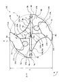
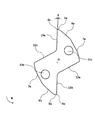
本実施形態のドリル100は、ドリル本体1の先端部2にドリル本体1の外周から回転軸O近傍のチゼルエッジ14まで形成された複数の凸円弧状切れ刃4a、4bと、凸円弧状切れ刃4a、4b間に形成されたシンニング12a、12bと、シンニング12a、12bの回転軸O方向後端からドリル本体1の後端側に向かって形成された溝15a、15bと、溝15a、15bの回転方向R後方にドリル本体1の外周端Wに沿って形成された第一マージン8a、8bと、溝15a、15bの回転方向R前方に外周端Wに沿って形成された第二マージン9a、9bとを有するドリル100であって、凸円弧状切れ刃4a、4bに沿って凸円弧状切れ刃4a、4bの回転方向R後方に形成された略帯状の二番面5a、5bと、この二番面5a、5bの回転方向R後方に連続して形成された三番面6a、6bと、この三番面6a、6bの回転方向R後方に連続して形成された四番面7a、7bとを有する。
The
本実施形態のドリル100の切れ刃は、より高い加工面品位を得るために、ドリル本体1の先端部2の外周から回転軸O近傍(ドリル本体1と回転軸Oとの先端側交点であるドリル本体1の先端50の近傍)のチゼルエッジ14まで凸円弧状に形成された凸円弧状切れ刃4a、4bである。切れ刃の枚数は2〜4枚が望ましい。切れ刃の枚数が2枚未満の場合は加工能率が低下し、切れ刃の枚数が4枚超の場合は切り屑排出領域が狭くなり、穴加工時に切り屑詰まりが発生しやすくなる虞がある。
The cutting edge of the
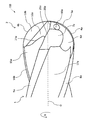
図1、図2に示すように、本発明のドリル100は、ドリル本体1を備える。ドリル本体1は、ドリル100の回転軸Oに対し互いに180°回転対称な形状を有する。ドリル本体1の先端側(図2の右側)に位置する先端部2には、回転軸Oに沿って2つの凸円弧状切れ刃4a、4bが形成されている。2つの切れ刃4a、4bは、凸円弧状に先端部2の外周からチゼルエッジ14まで、回転軸Oに平行な仮想平面上に延在している。ドリル本体1は、先端部2の後端側(図2の左側)に形成された円柱状のシャンク部(図示省略)を有する。
As shown in FIGS. 1 and 2, a
切れ刃4a、4bに対しドリル本体1の回転方向R前方には、すくい面13a、13bがそれぞれ形成されている。すくい面13a、13bは、切れ刃4a、4b(切れ刃4a、4bの稜線)と、切れ刃4a、4bの回転軸O方向後端とチゼルエッジ14の端部を結ぶ直線と、で囲まれた平面である。すくい面13a、13bは、図6に示すように、所定のすくい角δを有する。
Rake surfaces 13a and 13b are formed in front of the cutting
切れ刃4a、4bの回転方向R後方にはそれぞれ二番面5a、5bが連続して形成されており、二番面5a、5bはチゼルエッジ14を介して互いに接続している。図1において、二番面5a、5bは、ドリル本体1の先端部2の外周から回転軸Oの近傍(ドリル本体1の先端50の近傍)のチゼルエッジ14まで、凸円弧状切れ刃4a、4bに沿って略帯状に形成されている。図3に示すように、二番面5a、5bは、所定の二番角α(回転軸O方向の逃げ角であり、回転軸Oに垂直な面と二番面5a、5bとがなす角)を有する。
二番面5a、5bの回転方向R後方にはそれぞれ三番面6a、6bが連続して形成されている。図2、3に示すように、三番面6a、6bは、二番面5a、5bの回転方向R後方端を画定する線(27a、27b)から回転方向R後方及び回転軸O方向後端側に延在している。三番面6a、6b上には、それぞれオイルホール10a、10bが開口している。オイルホール10a、10bは、ドリル本体1内部において回転軸O方向に延びる貫通孔である。図3に示すように、三番面6a、6bは、所定の三番角β(回転軸O方向の逃げ角であり、回転軸Oに垂直な面と三番面6a、6bとがなす角)を有する。後述するように、三番角βは二番角αより大きい。
三番面6a、6bの回転方向R後方にはそれぞれ四番面7a、7bが連続して形成されている。より詳細には、四番面7a、7bは、三番面6a、6bの回転方向R後方且つ回転軸O方向後端側に接続している。図1、2、4に示すように、四番面7a、7bの回転方向R後方端を画定する線(21a、21b)は三番面6a、6bの回転方向R後方端を画定する線(20a、20b)と連続しており、三番面6a、6bと四番面7a、7bとにより略扇形状領域が形成されている。図3に示すように、四番面7a、7bは、所定の四番角γ(回転軸O方向の逃げ角であり、回転軸Oに垂直な面と四番面7a、7bとがなす角)を有する。後述するように、四番角γは三番角βより大きい。
このように、凸円弧状切れ刃4a、4bの回転方向R後方には、二番面5a、5b、三番面6a、6b、四番面7a、7bとがこの順に連続して形成されており、これらの面が凸円弧状切れ刃4a、4bの逃げ面として機能する。
As described above, the
凸円弧状切れ刃4a、4bの回転方向R前方にはそれぞれシンニング12b、12aが設置されている。詳細には、シンニング12a、12bはすくい面13b、13aの回転方向R前方、且つ三番面6a、6b及び四番面7a、7bの回転方向R後方に連続して形成されている。図1、4、5に示すように、シンニング12a、12bは、チゼルエッジ14近傍において二番面5a、5bと接続し、ドリル本体1の先端側から後端側に向かって回転方向Rにおける幅が大きくなっている。
シンニング12a、12bの後端側に、シンニング12a、12bと連続する溝15a、15bが形成されている。溝15a、15bは所定のねじれ角でドリル本体1の後端側に向かって螺旋状に延設されている。
溝15a、15bの回転方向R後方に外周端Wに沿って第一マージン8b、8aが形成されている。図1に示すように、第一マージン8a、8bは、ドリル100の直径Dを有する仮想円筒面である外周端Wに沿って形成された凸曲面である。より詳細には、第一マージン8a、8bの回転方向R前方端は外周端W上に位置し、第一マージン8a、8bの回転方向R後方端は外周端Wから径方向内方に僅かに離れている。第一マージン8a、8bは、溝15b、15aに沿ってドリル本体1の後端側に向かって螺旋状に延びる。図3に示すように、第一マージン8a、8bはその回転軸O方向先端側において、切れ刃4a、4b、二番面5a、5b、及び三番面6a、6bの後端と連続している。
溝15a、15bの回転方向R前方に外周端Wに沿って第二マージン9a、9bが形成されている。より詳細には、図1に示すように、第二マージン9a、9bの回転方向R後方端は外周端W上に位置し、第二マージン9a、9bの回転方向R前方端は外周端Wから径方向内方に僅かに離れている。第二マージン9a、9bは、溝15a、15bに沿ってドリル本体1の後端側に向かって螺旋状に延びる凸曲面である。図2、4に示すように、第二マージン9a、9bはその回転軸O方向先端において、四番面7a、7bの後端と連続している。
第一マージン8a、8bと第二マージン9a、9bとの間には、切削加工時の抵抗を減らすために二番取り面17a、17bが形成されている。より詳細には、二番取り面17a、17bは、第一マージン8a、8bの回転方向R後方かつ第二マージン9a、9bの回転方向R前方に連続して形成されている。二番取り面17a、17bは、第一マージン8a、8bと第二マージン9a、9bよりも径方向内方に位置し、第一マージン8a、8bと第二マージン9a、9bとに沿ってこれらの間をドリル本体1の後端側に向かって螺旋状に延びる凸曲面である。
Between the
図2、5に示すように、第一マージン8a、8bと溝15b、15aとの間には、第一マージン8a、8bの強度を高めるために、径方向に対する角度が負角の面であるネガランド16a、16b(16aは図2、5から見えない。)が、第一マージン8a、8b及び溝15b、15aに沿って形成されている。図1に示すように、第二マージン9a、9bと溝15a、15bとの間には、ヒール11a、11bが、第二マージン9a、9b及び溝15b、15aに沿って形成されている。ヒール11a、11bは、その径方向内端が外端よりも回転方向R後方に位置するように径方向に対し傾斜した面である。
As shown in FIGS. 2 and 5, between the
このように、溝15aの回転方向R前方には、ヒール11a、第二マージン9a、二番取り面17a、第一マージン8a、及びネガランド16aがこの順に連続して設けられている。溝15bの回転方向R前方には、ヒール11b、第二マージン9b、二番取り面17b、第一マージン8b、及びネガランド16bが順に連続して設けられている。
Thus, in front of the rotation direction R of the
本実施形態の溝15a、15bのねじれ角は、被削材や加工条件に合わせて0°〜40°の範囲から適宜選択することができる(本実施形態のねじれ角は20°である。)。硬い材料に深穴加工を行う際には、剛性確保のために小さいねじれ角を有する溝15a、15bを形成し、軟らかい材料には切り屑排出性を向上させるために大きいねじれ角を有する溝15a、15bを形成することが望ましい。
The twist angles of the
略帯状に形成されている二番面5a、5bの最大幅Gは0.02D〜0.1D(Dはドリル100の直径)の範囲内に形成されることが望ましく、0.03D〜0.07Dの範囲内に形成されることがより望ましい。最大幅Gを0.02D〜0.1Dの範囲内で形成することにより、図3のように二番面5a、5bよりも大きい角度でドリル本体1の後端側に傾斜している三番面6a、6b及び四番面7a、7bの形成領域(即ち、二番面5a、5bとシンニング12a、12bとの間の領域)を従来のドリルよりも大きくすることができる。このため、従来よりも切り屑排出領域を広くすることができる。最大幅Gが、0.02D未満の場合は刃先の剛性が低下する虞があり、0.1D超では切り屑排出領域が狭くなり、切り屑詰まりが多発する虞がある。ここで「略帯状」とは切れ刃4a、4bと、二番面5a、5bと三番面6a、6bとの境界27a、27bとがほぼ平行(二番面5a、5bの最大幅と最小幅との差が0.08D以内)になるように二番面5a、5bが形成されていることを意味する。このとき二番面5a、5bと三番面6a、6bとの境界27a、27bは直線、曲線または直線と曲線との組合せの中から選択することができる。また、二番面5a、5bの幅とは、回転方向Rにおける二番面5a、5bの幅を意味する。
The maximum width G of the
図1、図3に示すように、二番面5a、5bの回転方向R後方には、二番角αよりも大きい三番角βでドリル本体1の後端側に傾斜している三番面6a、6bが形成されている。三番面6a、6bの回転方向R後方には、三番角βよりも大きい四番角γでドリル本体1の後端側に傾斜している四番面7a、7bが形成されている。本実施形態のドリル100は、これらの二番面5a、5b、三番面6a、6b、及び四番面7a、7bを有することにより、ドリルの先端部2の切れ刃4a、4bの厚みを従来よりも増加させることができるので、切れ刃4a、4bの剛性を向上させつつ、傾斜角が大きい四番角γにより広い切り屑排出領域を確保することができる。
As shown in FIG. 1 and FIG. 3, the third surface which is inclined to the rear end side of the
ここで二番面5a、5b、三番面6a、6b、四番面7a、7bは平面、曲面または平面と曲面とが組み合わさった面を選択してもよいが、曲面を選択した際は径方向外方に凸である曲面を用いることが望ましい。凹曲面を使用した場合、ドリルの剛性が低下し、折損が発生する可能性が高まる。
Here, the
また、二番角αの角度は10〜30°、三番角βの角度は25〜45°、四番角γの角度は50〜70°(但し、α<β<γ)であることが望ましい。角度α、β、γが上記数値範囲の下限を下回った場合、切削時の抵抗が増大する傾向にあり、上記数値範囲の上限を上回った場合、ドリルの剛性が低下する場合がある。二番角αの角度は12〜20°、三番角βの角度は27〜40°、四番角γの角度は55〜65°(但し、α<β<γ)であることがより望ましい。 The angle of the second angle α is 10 to 30 °, the angle of the third angle β is 25 to 45 °, and the angle of the fourth angle γ is 50 to 70 ° (where α <β <γ). desirable. When the angles α, β, and γ are below the lower limit of the numerical range, the resistance during cutting tends to increase. When the angles α, β, and γ are higher than the upper limit of the numerical range, the rigidity of the drill may be reduced. More preferably, the angle of the second angle α is 12 to 20 °, the angle of the third angle β is 27 to 40 °, and the angle of the fourth angle γ is 55 to 65 ° (where α <β <γ). .
本実施形態のドリルの先端部2に設けられている凹曲面状のシンニング12aについて、切り屑排出性を向上させるために、図1に示すように、ドリル本体1の先端側から見たとき、シンニング12aと三番面6aとの境界20aと切れ刃4bとのなす角度θは、80〜110°であることが望ましく、85〜100°であることがより望ましい。シンニング12bと三番面6bとの境界20bと切れ刃4aとのなす角度θも同様である。角度θが85°未満の場合はシンニング12a、12bの領域が狭くなるので切り屑排出性が低下する場合がある。角度θが110°超の場合は二番面5a、5b、三番面6a、6bが小さくなって剛性が低下する虞があると共に、第一、第二マージン8a、8b、9a、9bを形成する領域も狭くなり、ガイド性の低下により穴壁にびびりを生じやすくなる虞がある。
For the concave curved thinning 12a provided at the
図1に示すように、ドリル本体1の先端側から見たとき、シンニング12aと三番面6aとの境界20aは直線状に形成されていることが望ましい。境界20aが直線状に形成されることにより、切り屑が境界20aで分断されやすくなり、切り屑排出性能がさらに向上する。境界20aが曲線状でも切り屑分断効果を発揮するが、直線状のものより切り屑排出性能が劣る傾向にある。同様にシンニング12bと三番面6bとの境界20bは直線状に形成されていることが望ましい。なお、境界20a、20bが曲線状の場合は、境界20a、20bと境界21a、21との交点と境界20a、20bと境界27a、27bとの交点とを結ぶ直線と、切れ刃4b、4aとのなす角度を境界20a、20bと切れ刃4b、4aとのなす角度θと見なす。
As shown in FIG. 1, it is desirable that the
図1に示すように、ドリル本体1の先端側から見たとき、シンニング12a、12bと溝15a、15bとの境界23a、23bに内接する円(心厚円)Uを描いたとき、内接円の直径(心厚)Dwは、ドリル100の直径Dの30〜50%であることが望ましく、35〜45%であることがより望ましい。本実施形態のドリル100の切れ刃4a、4bは凸円弧状であるため、先端形状が略三角形となる従来のドリルよりも切削加工時の抵抗が増大する傾向にある。そのため上記のように比較的大きい心厚を有することにより、ドリル100の折損を防ぎ、安定した加工が可能となる。内接円の直径Dwがドリル100の直径Dの30%未満の場合、切削加工時に折損する可能性が高まる。内接円の直径Dwがドリル100の直径Dの50%超の場合、切り屑排出性が低下する虞がある。
As shown in FIG. 1, when viewed from the front end side of the
図1に示すように、ドリル本体1の先端側から見たとき、シンニング12aと四番面7aとの境界21aとシンニング12aと三番面6aとの境界20aとがなす角度εは、35〜55°であることが望ましい。同様に、シンニング12bと四番面7bとの境界21bとシンニング12bと三番面6bとの境界20bとがなす角度εは35〜55°であることが望ましい。角度εが35°未満の場合、第二マージン9a、9bの回転軸O方向の厚みが薄くなり、第二マージン9a、9bの剛性が低下する虞がある。角度εが55°超の場合、シンニング12a、12bの領域が狭くなり、切り屑排出性が低下する虞がある。なお、境界20a、20bが曲線状の場合は、境界20a、20bと境界21a、21との交点と境界20a、20bと境界27a、27bとの交点とを結ぶ直線と、境界21a、21bとのなす角度を境界20a、20bと境界21a、21bとのなす角度εと見なす。
As shown in FIG. 1, when viewed from the tip side of the
図1に示すように、ドリル本体1の先端側から見たとき、シンニング12aと四番面7aとの境界点Pは回転軸Oからの距離が0.2D〜0.45Dの範囲内で形成されることが望ましい。境界点Pは、シンニング12aと四番面7aとの境界21a上の径方向最外方に位置する点であり、言い換えると、シンニング12aと溝15aとの境界23aと四番面7aとの交点である。境界点Pが上記の位置に現れるようにシンニング12aを形成することにより、第二マージン9aの強度を向上させつつ、シンニング12aを広くすることができる。境界点Pと回転軸Oとの距離が0.2D未満の場合、シンニング12aの領域が狭くなり、切り屑排出性能が低下する虞がある。境界点Pと回転軸Oとの距離が0.45D超の場合、シンニング12aの領域が過大となり、四番面7aが狭くなり、剛性が低下する傾向にある。同様に、シンニング12bと四番面7bとの境界点Pは回転軸Oからの距離が0.2D〜0.45Dの範囲内で形成されることが望ましい。境界点Pと回転軸Oとの距離は、0.30D〜0.40Dであることがより好ましい。
As shown in FIG. 1, when viewed from the distal end side of the
図1に示すように、ドリル本体1の先端側から見たとき、シンニング12a、12bと切れ刃4b、4aとの境界点Qは回転軸Oからの距離が0.25D〜0.5Dの範囲内で形成されることが望ましい。境界点Qは、シンニング12a、12bと切れ刃4a、4bとの境界上の径方向最外方に位置する点であり、言い換えると、シンニング12a、12bと溝15a、15bとの境界23a、23bと切れ刃4a、4bとの交点である。境界点Qが上記の位置に現れるようにシンニング12a、12bを形成することで、シンニング12a、12bを広くすることができる。境界点Qと回転軸Oとの距離が0.25D未満の場合、シンニング12a、12bの領域が狭くなり、切り屑排出性能が低下する虞がある。境界点Qと回転軸Oとの距離は、0.30D〜0.40Dであることがより好ましい。
As shown in FIG. 1, when viewed from the front end side of the
本実施形態のドリル100の第二マージン9a、9bは、四番面7a、7bの回転軸O方向後端に連続して形成されていることが望ましい。この構成により、図2に示すように、第二マージン9a、9bの始端(回転軸O方向先端)側にシンニング12a、12bが干渉しないので、第二マージン9a、9bの幅を広くすることができる。その結果、切削加工時の安定性が向上する。この第二マージン9a、9bが三番面6a、6bまで形成された場合、第二マージン9a、9bの幅が広くなりすぎ、切削抵抗が増大する虞がある。
The
図5に示すように、本実施形態のドリル100のすくい面13bの回転軸O方向後端Tは、第一マージン8bの回転軸O方向先端Sよりもドリル本体1の後端側に位置していることが望ましい。上記の条件を満たすことで、TS間において切れ刃4bの回転方向R後方に第一マージン8bが、切れ刃4bの回転方向R前方にすくい面13bが配置される。言い換えると、切れ刃4bを境に、すくい面13bの終端が第一マージン8bの始端よりも回転方向R後方に位置する。このTS間に切れ刃4bが形成されたドリル100を用いて切削加工を行うと、被削面に第一マージン8bが擦れるように接触するので、バニシング作用により高品位な穴加工面を得ることが可能である。ここで、ドリル本体1の先端側から見たとき、第一マージン8bの回転軸O方向先端Sとすくい面13bの回転軸O方向後端Tとの距離は、0.03D〜0.3Dの範囲内で形成されることが望ましい。上記の距離が0.03D未満の場合、TS間の切れ刃4bが微小にしか形成できないため、より高品質な加工面品位を得ることができない。0.3D超の場合、二番面5bの形成領域が小さくなり、切削抵抗が増加する虞がある。当該距離は、より好ましくは0.05D〜0.15Dである。なお、すくい面13aと第一マージン8aについても同様である。
As shown in FIG. 5, the rear end T of the
図3において、第一マージン8aの回転軸O方向先端Sから三番面6aの回転軸O方向後端(第一マージン8aと三番面6aとの境界26の回転軸O方向後端)Xまで第一マージン8aの幅(回転方向Rの幅)が漸増していることが望ましい。このように第一マージン8aの幅を構成することにより、切削加工時の負荷を低減することができる。また、図3に示すように、第一マージン8aと二番面5aとの境界25、及び第一マージン8aと三番面6aとの境界26は回転方向R前方に向かって凸円弧状とすることにより、さらに切削負荷を低減させることができる。なお、第一マージン8bの幅、及び第一マージン8bと二番面5b及び三番面6bとの境界についても同様である。
In FIG. 3, the rear end of the
図6はドリル100の先端50からドリル本体1の回転軸O方向後端方向に0.15D離れた位置における、回転軸Oに直交する断面図(図3のI-I断面図)である。本実施形態のドリル100において、先端50から0.03D〜0.35Dの範囲内における径方向すくい角δは、刃先の剛性を保つために−5〜−0.5°であることが望ましい。径方向すくい角δを−0.5°よりも大きく設定した場合、刃先の剛性不足によりチッピングが発生する虞がある。径方向すくい角δを−5°よりも負角に設定した場合、切削抵抗が増加する傾向にある。径方向すくい角δは、-4〜-1°がより好ましい。
6 is a cross-sectional view (II cross-sectional view of FIG. 3) perpendicular to the rotation axis O at a position 0.15D away from the
以上、本発明の実施形態であるドリルについて説明したが、本発明はこれに限定されることはなく、その発明の技術的思想を逸脱しない範囲で適宜変更可能である。上記実施形態では2つの切れ刃を備えるドリルについて説明したが、これに限定されない。切れ刃の数が3または4の場合にも、上述の構成とすることにより、本発明の効果を奏することができる。なお、この場合は、ドリル本体の形状を回転軸に対し120°または90°の回転対称とすれば良い。 As mentioned above, although the drill which is embodiment of this invention was demonstrated, this invention is not limited to this, It can change suitably in the range which does not deviate from the technical idea of the invention. Although the said embodiment demonstrated the drill provided with two cutting edges, it is not limited to this. Even when the number of cutting blades is 3 or 4, the effects of the present invention can be achieved by adopting the above-described configuration. In this case, the shape of the drill body may be 120 ° or 90 ° rotationally symmetric with respect to the rotation axis.
本発明のドリルによれば、刃先の剛性を確保しつつ、高い切屑排出性が得られるので、穴あけ加工において高品位な加工面を得られる。 According to the drill of the present invention, high chip discharge is obtained while ensuring the rigidity of the cutting edge, so that a high-quality processed surface can be obtained in drilling.
100 ドリル
1 ドリル本体
2 ドリル本体の先端部
4a、4b:凸円弧状切れ刃
5a、5b:二番面
6a、6b:三番面
7a、7b:四番面
8a、8b:第一マージン(溝15a、15bの回転方向R後方の外周端)
9a、9b:第二マージン(溝15a、15bの回転方向R前方の外周端)
10a、10b:オイルホール
11a、11b:ヒール
12a、12b:シンニング
13a、13b:すくい面
14:チゼルエッジ
15a、15b:溝
16a、16b:ネガランド
17a、17b:二番取り面
20a、20b:シンニングと三番面との境界
21a、21b:シンニングと四番面との境界
23a、23b:シンニングと溝との境界
25:二番面と第一マージンとの境界
26:三番面と第一マージンとの境界
27a、27b:二番面と三番面との境界
50:ドリル本体の先端
100:ドリル
D:ドリルの直径
Dw:心厚
G:二番面の幅
O:回転軸
P:シンニングと四番面との境界点
Q:シンニングと切れ刃との境界点
R:回転方向
S:第一マージンの始端(回転軸方向先端)
T:すくい面の終端(回転軸方向後端)
U:心厚円
X:三番面の終端(回転軸方向後端)
W:外周端
α:二番角
β:三番角
γ:四番角
δ:すくい角
ε:シンニングと三番面との境界と、シンニングと四番面との境界とのなす角
θ:シンニングと三番面との境界と切れ刃のなす角
100 drill
1 Drill body
2 Drill body tip
4a, 4b: Convex arcuate cutting edge
5a, 5b: Second side
6a, 6b: Third face
7a, 7b: No. 4
8a, 8b: First margin (outer peripheral edge behind the rotation direction R of the
9a, 9b: Second margin (outer peripheral edge in front of rotation direction R of
10a, 10b: Oil hole
11a, 11b: Heel
12a, 12b: Thinning
13a, 13b: Rake face
14: Chisel edge
15a, 15b: Groove
16a, 16b: Negative Land
17a, 17b: Second face
20a, 20b: The boundary between thinning and third surface
21a, 21b: The boundary between thinning and the fourth surface
23a, 23b: Thinning and groove boundary
25: The boundary between the second side and the first margin
26: The boundary between the third face and the first margin
27a, 27b: Boundary between the second and third surfaces
50: Tip of drill body
100: Drill
D: Diameter of drill
Dw: Heart thickness
G: Width of the second side
O: Rotation axis
P: Boundary point between thinning and fourth surface
Q: Boundary point between thinning and cutting edge
R: Direction of rotation
S: Start of the first margin (tip in the rotation axis direction)
T: End of rake face (rear end in rotation axis direction)
U: Heart thick circle
X: End of the third surface (rear end in the rotation axis direction)
W: Outer edge α: Second angle β: Third angle γ: Fourth angle δ: Rake angle ε: Angle between the boundary between thinning and third surface and the boundary between thinning and fourth surface θ: Thinning The angle between the boundary between the surface and the third surface and the cutting edge
Claims (11)
前記凸円弧状切れ刃に沿って前記凸円弧状切れ刃の回転方向後方に形成された略帯状の二番面と、前記二番面の回転方向後方に連続して形成された三番面と、前記三番面の回転方向後方に連続して形成された四番面とを有し、
前記凸円弧状切れ刃のすくい面の回転軸方向後端が前記第一マージンの回転軸方向先端よりも前記ドリル本体の回転軸方向後端側に位置することを特徴とするドリル。 A plurality of convex arcuate cutting edges formed on the distal end side of the drill body from the outer periphery of the drill body to a chisel edge near the rotation axis, a thinning formed between the convex arcuate cutting edges, and a rotation axis direction of the thinning A groove formed from the rear end toward the rear end side of the drill body, a first margin formed along the outer peripheral edge of the drill body at the rear in the rotation direction of the groove, and at the front in the rotation direction of the groove A drill having a second margin formed along the outer peripheral edge,
A substantially strip-shaped second surface formed behind the convex arc-shaped cutting edge in the rotational direction of the convex arc-shaped cutting blade, and a third surface formed continuously behind the second surface in the rotational direction. , And the fourth surface formed continuously in the rotational direction rear of the third surface,
A drill, characterized in that the rear end in the rotation axis direction of the rake face of the convex arcuate cutting edge is located closer to the rear end in the rotation axis direction of the drill body than the front end in the rotation axis direction of the first margin.
前記ドリル本体の先端側から見たとき、前記シンニングと前記三番面との境界が直線状に形成されていることを特徴とするドリル。 The drill according to any one of claims 1 to 3,
When viewed from the front end side of the drill body, the boundary between the thinning and the third surface is formed in a straight line.
前記シンニングはその先端側において前記三番面の回転方向後方に連続し、
前記シンニングはその後端側において前記四番面の回転方向後方に連続し、
前記ドリル本体の先端側から見たとき、前記シンニングと前記三番面との境界と、当該シンニングと前記四番面との境界とのなす角度が35〜55°であることを特徴とするドリル。 The drill according to any one of claims 1 to 5,
The thinning continues to the rear side in the rotational direction of the third surface on the tip side,
The thinning continues on the rear end side behind the fourth surface in the rotational direction,
When viewed from the front end side of the drill body, an angle formed by a boundary between the thinning and the third surface and a boundary between the thinning and the fourth surface is 35 to 55 °. .
前記シンニングは前記四番面の回転方向後方に連続し、
前記ドリル本体の先端側から見たとき、前記シンニングと前記四番面との境界上の径方向最外方に位置する点と前記回転軸との距離が0.2D〜0.45D(Dは当該ドリルの直径)であることを特徴とするドリル。 The drill according to any one of claims 1 to 6,
The thinning continues to the rear of the fourth surface in the rotational direction,
When viewed from the front end side of the drill body, the distance between the outermost point on the boundary between the thinning and the fourth surface and the rotational axis is 0.2D to 0.45D (D is the drill The diameter of the drill.
前記第一マージンは前記三番面の回転軸方向後端に連続しており、
前記第一マージンの回転軸方向先端から、前記第一マージンと前記三番面との境界の回転軸方向後端まで、前記第一マージンの幅が漸増していることを特徴とするドリル。 The drill according to any one of claims 1 to 8,
The first margin is continuous with the rear end in the rotation axis direction of the third surface,
The drill according to claim 1, wherein the width of the first margin gradually increases from the front end of the first margin in the rotational axis direction to the rear end in the rotational axis direction of the boundary between the first margin and the third surface.
前記第一マージンは前記二番面及び前記三番面の回転軸方向後端に連続しており、
前記第一マージンと前記二番面との境界、及び前記第一マージンと前記三番面との境界が、回転方向前方に凸となる円弧であることを特徴とするドリル。 The drill according to any one of claims 1 to 9,
The first margin is continuous with the rear end in the rotation axis direction of the second surface and the third surface,
The drill characterized by the boundary between said 1st margin and said 2nd surface, and the boundary between said 1st margin and said 3rd surface being the circular arc which protrudes ahead in the rotation direction.
前記ドリル本体の先端から前記回転軸方向に0.03D〜0.35D(Dは当該ドリルの直径)の範囲において、前記凸円弧状切れ刃のすくい角が−5〜0.5°であることを特徴とするドリル。 The drill according to any one of claims 1 to 10,
In the range of 0.03D to 0.35D (D is the diameter of the drill) from the tip of the drill body in the direction of the rotation axis, the rake angle of the convex arcuate cutting edge is −5 to 0.5 °. And drill.
Applications Claiming Priority (2)
| Application Number | Priority Date | Filing Date | Title |
|---|---|---|---|
| JP2015069419 | 2015-03-30 | ||
| JP2015069419 | 2015-03-30 |
Related Parent Applications (1)
| Application Number | Title | Priority Date | Filing Date |
|---|---|---|---|
| JP2016548201A Division JP6057038B1 (en) | 2015-03-30 | 2016-03-17 | drill |
Publications (2)
| Publication Number | Publication Date |
|---|---|
| JP2017013231A true JP2017013231A (en) | 2017-01-19 |
| JP6086174B2 JP6086174B2 (en) | 2017-03-01 |
Family
ID=57004238
Family Applications (6)
| Application Number | Title | Priority Date | Filing Date |
|---|---|---|---|
| JP2016548201A Active JP6057038B1 (en) | 2015-03-30 | 2016-03-17 | drill |
| JP2016203826A Active JP6086172B2 (en) | 2015-03-30 | 2016-10-17 | drill |
| JP2016203827A Active JP6086173B2 (en) | 2015-03-30 | 2016-10-17 | drill |
| JP2016203828A Active JP6086174B2 (en) | 2015-03-30 | 2016-10-17 | drill |
| JP2016203825A Active JP6086171B2 (en) | 2015-03-30 | 2016-10-17 | drill |
| JP2016203824A Active JP6086170B2 (en) | 2015-03-30 | 2016-10-17 | drill |
Family Applications Before (3)
| Application Number | Title | Priority Date | Filing Date |
|---|---|---|---|
| JP2016548201A Active JP6057038B1 (en) | 2015-03-30 | 2016-03-17 | drill |
| JP2016203826A Active JP6086172B2 (en) | 2015-03-30 | 2016-10-17 | drill |
| JP2016203827A Active JP6086173B2 (en) | 2015-03-30 | 2016-10-17 | drill |
Family Applications After (2)
| Application Number | Title | Priority Date | Filing Date |
|---|---|---|---|
| JP2016203825A Active JP6086171B2 (en) | 2015-03-30 | 2016-10-17 | drill |
| JP2016203824A Active JP6086170B2 (en) | 2015-03-30 | 2016-10-17 | drill |
Country Status (6)
| Country | Link |
|---|---|
| US (1) | US10279398B2 (en) |
| EP (1) | EP3278911B1 (en) |
| JP (6) | JP6057038B1 (en) |
| KR (1) | KR101983487B1 (en) |
| CN (1) | CN107427935B (en) |
| WO (1) | WO2016158463A1 (en) |
Families Citing this family (13)
| Publication number | Priority date | Publication date | Assignee | Title |
|---|---|---|---|---|
| JP6589462B2 (en) * | 2015-08-27 | 2019-10-16 | 三菱マテリアル株式会社 | Drill |
| CN109862981B (en) * | 2016-10-26 | 2020-06-12 | 京瓷株式会社 | Cutting tool and method for manufacturing cut product |
| US11370039B2 (en) * | 2017-09-07 | 2022-06-28 | Osg Corporation | Drill |
| JP7185127B2 (en) * | 2018-04-25 | 2022-12-07 | 株式会社Moldino | Drill |
| US11229959B2 (en) * | 2018-08-07 | 2022-01-25 | Sumitomo Electric Hardmetal Corp. | Drill |
| DE102019202165B4 (en) * | 2019-02-19 | 2022-10-27 | Kennametal Inc. | Drill and method of machining a workpiece |
| CN110076375A (en) * | 2019-05-05 | 2019-08-02 | 厦门金鹭特种合金有限公司 | A kind of monoblock type fluted drill |
| DE102019211827B4 (en) * | 2019-08-07 | 2023-10-19 | Kennametal Inc. | Drill and method of making a drill |
| DE102019129767A1 (en) * | 2019-11-05 | 2021-05-06 | Audi Ag | Twist drill |
| US20230031453A1 (en) * | 2019-12-11 | 2023-02-02 | Kyocera Corporation | Drill and method for manufacturing machined product |
| KR20210076527A (en) | 2019-12-16 | 2021-06-24 | 유림툴스주식회사 | Drill |
| US11951553B2 (en) * | 2021-03-29 | 2024-04-09 | Iscar, Ltd. | Rotatable cutting head having tip portion with three radially extending cutting edges forming a rectilinear rotational profile |
| JP7422442B1 (en) | 2023-06-23 | 2024-01-26 | 株式会社メドメタレックス | Drill |
Citations (4)
| Publication number | Priority date | Publication date | Assignee | Title |
|---|---|---|---|---|
| JPH09136206A (en) * | 1995-11-14 | 1997-05-27 | Unisia Jecs Corp | Twist drill provided with oil holes |
| JP2005199418A (en) * | 2003-12-17 | 2005-07-28 | Mitsubishi Materials Corp | Drill |
| JP2006525127A (en) * | 2003-05-09 | 2006-11-09 | ギューリング,イェルク | Drill tool for cutting cast material |
| WO2013065201A1 (en) * | 2011-11-04 | 2013-05-10 | オーエスジー株式会社 | Drill |
Family Cites Families (39)
| Publication number | Priority date | Publication date | Assignee | Title |
|---|---|---|---|---|
| US3443459A (en) * | 1968-02-14 | 1969-05-13 | Bruce Alexander Mackey | Drill |
| US4116580A (en) * | 1977-04-08 | 1978-09-26 | Mcdonnell Douglas Corporation | All cutting edge drill |
| JPS5531535A (en) * | 1978-08-21 | 1980-03-05 | Toshiaki Hosoi | Twist drill |
| JPS5531536A (en) * | 1978-08-21 | 1980-03-05 | Toshiaki Hosoi | Twist drill |
| JPS5771714A (en) * | 1980-10-23 | 1982-05-04 | Toshiba Corp | Drill for hard to cutting material |
| JPS6056809A (en) | 1983-09-08 | 1985-04-02 | Nachi Fujikoshi Corp | Drill |
| JP2508524B2 (en) * | 1987-03-27 | 1996-06-19 | 三菱マテリアル株式会社 | Drill |
| JPS63216610A (en) * | 1987-03-04 | 1988-09-08 | Mitsubishi Metal Corp | Drill |
| JPS63237807A (en) * | 1987-03-25 | 1988-10-04 | Mitsubishi Metal Corp | Drill |
| JPH078447B2 (en) * | 1987-08-06 | 1995-02-01 | 株式会社神戸製鋼所 | Drill for thin plate processing |
| JP2516412B2 (en) * | 1988-10-17 | 1996-07-24 | 東芝タンガロイ株式会社 | Straight drill with oil hole |
| JP2905555B2 (en) * | 1990-05-16 | 1999-06-14 | 東芝タンガロイ株式会社 | Twist drill |
| JPH0615512A (en) * | 1992-07-03 | 1994-01-25 | Toshiaki Hosoi | Drill and formation of cutting blade of drill |
| JP2599549B2 (en) * | 1993-05-14 | 1997-04-09 | 俊明 細井 | Drill |
| DE4417166B4 (en) * | 1993-07-27 | 2006-02-16 | Mitsubishi Materials Corp. | drill |
| KR950031335A (en) * | 1994-05-13 | 1995-12-18 | 아키모토 유우미 | drill |
| JPH0938816A (en) * | 1995-08-01 | 1997-02-10 | Mitsubishi Materials Corp | Drill |
| DE19602566A1 (en) * | 1996-01-25 | 1997-07-31 | Andre Woitschach Gmbh | Pointed drill for use with hard metal |
| GB9606370D0 (en) * | 1996-03-26 | 1996-06-05 | Dormer Tools Sheffield Ltd | Improvements in or relating to twist drills |
| JP3170203B2 (en) * | 1996-08-19 | 2001-05-28 | オーエスジー株式会社 | Drill grinding method and drill |
| IL123858A (en) * | 1998-03-27 | 2003-05-29 | Iscar Ltd | Drilling head |
| JP2001079707A (en) * | 1999-09-13 | 2001-03-27 | Toshiba Tungaloy Co Ltd | Twist drill |
| EP1275458A1 (en) * | 2001-07-10 | 2003-01-15 | Mitsubishi Materials Corporation | Drill |
| US6676342B2 (en) * | 2002-01-09 | 2004-01-13 | Allied Machine & Engineering Corp. | Drill with specialized drill point geometry |
| DE10346217A1 (en) * | 2003-09-24 | 2005-04-28 | Mapal Fab Praezision | drill |
| EP1577904B1 (en) * | 2004-03-15 | 2012-02-22 | ABB Research Ltd. | High voltage bushing with element for electric-field control |
| JP3874774B2 (en) * | 2004-08-19 | 2007-01-31 | オーエスジー株式会社 | Cast hole drill |
| JP2006055965A (en) * | 2004-08-23 | 2006-03-02 | Osg Corp | Cemented carbide drill causing low work hardening |
| US7575401B1 (en) * | 2004-11-18 | 2009-08-18 | Precorp, Inc. | PCD drill for composite materials |
| KR100649431B1 (en) * | 2006-01-23 | 2006-11-28 | 남궁규성 | Drill provided with fluid guide means |
| JP2008149412A (en) * | 2006-12-18 | 2008-07-03 | Mitsubishi Materials Corp | Drill |
| DE102008004564B4 (en) * | 2008-01-15 | 2013-04-11 | EMUGE-Werk Richard Glimpel GmbH & Co. KG Fabrik für Präzisionswerkzeuge | Burr tool with point |
| KR101526642B1 (en) * | 2008-06-28 | 2015-06-05 | 귀링 카게 | Multiple edge drill |
| JP2011073129A (en) * | 2009-10-01 | 2011-04-14 | Hitachi Tool Engineering Ltd | Boring drill |
| SE536296C2 (en) * | 2011-02-08 | 2013-08-06 | Sandvik Intellectual Property | Drill with chip channels designed for improved chip evacuation |
| US8929236B2 (en) * | 2012-07-30 | 2015-01-06 | Hewlett-Packard Development Company, L.P. | Network flow analysis |
| JP5975340B2 (en) | 2012-10-25 | 2016-08-23 | 住友電工ハードメタル株式会社 | drill |
| CN202861476U (en) * | 2012-11-12 | 2013-04-10 | 江西杰浩硬质合金工具有限公司 | High-efficiency high-precision deep hole drill |
| US20150043983A1 (en) * | 2013-08-06 | 2015-02-12 | Performance Carbide, Inc. | Spade drill |
-
2016
- 2016-03-17 US US15/554,503 patent/US10279398B2/en active Active
- 2016-03-17 CN CN201680013296.8A patent/CN107427935B/en active Active
- 2016-03-17 JP JP2016548201A patent/JP6057038B1/en active Active
- 2016-03-17 EP EP16772346.9A patent/EP3278911B1/en active Active
- 2016-03-17 KR KR1020177024921A patent/KR101983487B1/en active IP Right Grant
- 2016-03-17 WO PCT/JP2016/058549 patent/WO2016158463A1/en active Application Filing
- 2016-10-17 JP JP2016203826A patent/JP6086172B2/en active Active
- 2016-10-17 JP JP2016203827A patent/JP6086173B2/en active Active
- 2016-10-17 JP JP2016203828A patent/JP6086174B2/en active Active
- 2016-10-17 JP JP2016203825A patent/JP6086171B2/en active Active
- 2016-10-17 JP JP2016203824A patent/JP6086170B2/en active Active
Patent Citations (4)
| Publication number | Priority date | Publication date | Assignee | Title |
|---|---|---|---|---|
| JPH09136206A (en) * | 1995-11-14 | 1997-05-27 | Unisia Jecs Corp | Twist drill provided with oil holes |
| JP2006525127A (en) * | 2003-05-09 | 2006-11-09 | ギューリング,イェルク | Drill tool for cutting cast material |
| JP2005199418A (en) * | 2003-12-17 | 2005-07-28 | Mitsubishi Materials Corp | Drill |
| WO2013065201A1 (en) * | 2011-11-04 | 2013-05-10 | オーエスジー株式会社 | Drill |
Also Published As
| Publication number | Publication date |
|---|---|
| CN107427935A (en) | 2017-12-01 |
| EP3278911A4 (en) | 2018-11-21 |
| JP2017007090A (en) | 2017-01-12 |
| JP6086173B2 (en) | 2017-03-01 |
| JP6086170B2 (en) | 2017-03-01 |
| WO2016158463A1 (en) | 2016-10-06 |
| JP6086172B2 (en) | 2017-03-01 |
| JP2017013230A (en) | 2017-01-19 |
| KR20170110706A (en) | 2017-10-11 |
| US20180043441A1 (en) | 2018-02-15 |
| JP2017013229A (en) | 2017-01-19 |
| JPWO2016158463A1 (en) | 2017-04-27 |
| EP3278911A1 (en) | 2018-02-07 |
| US10279398B2 (en) | 2019-05-07 |
| CN107427935B (en) | 2019-04-19 |
| JP6086174B2 (en) | 2017-03-01 |
| JP6057038B1 (en) | 2017-01-11 |
| EP3278911B1 (en) | 2020-04-15 |
| KR101983487B1 (en) | 2019-05-28 |
| JP2017007089A (en) | 2017-01-12 |
| JP6086171B2 (en) | 2017-03-01 |
Similar Documents
| Publication | Publication Date | Title |
|---|---|---|
| JP6086170B2 (en) | drill | |
| JP5013435B2 (en) | Ball end mill | |
| JP2006239829A (en) | Drill | |
| JP5368384B2 (en) | Deep hole drill | |
| JP2018176360A (en) | Rotary cutting type drilling tool | |
| JP2016064477A (en) | drill | |
| JP2010162645A (en) | Drill | |
| JP2010162643A (en) | Drill and grinding method of the drill | |
| JP2003275913A (en) | Drill | |
| JP2002205212A (en) | Drill | |
| JP6902284B2 (en) | Cutting tools | |
| JP2015131384A (en) | drill | |
| JP3686022B2 (en) | Drilling tool with coolant hole | |
| JP7138927B2 (en) | Drill | |
| JP2005177891A (en) | Drill | |
| JP5439821B2 (en) | Drill and grinding method of the drill | |
| JP2019115939A (en) | Rotary tool and manufacturing method of cutting workpiece | |
| JP4235001B2 (en) | Twist drill | |
| JPH0890323A (en) | Drill | |
| CN113795347A (en) | Cutting tool | |
| JP2006272532A (en) | Reamer | |
| JP2002301613A (en) | Drill with diamond sintered material | |
| JP2004195561A (en) | Drill | |
| JP2005059208A (en) | Drilling tool with coolant hole | |
| JP2009154231A (en) | Solid reamer |
Legal Events
| Date | Code | Title | Description |
|---|---|---|---|
| A621 | Written request for application examination |
Free format text: JAPANESE INTERMEDIATE CODE: A621 Effective date: 20161017 |
|
| A871 | Explanation of circumstances concerning accelerated examination |
Free format text: JAPANESE INTERMEDIATE CODE: A871 Effective date: 20161017 |
|
| A975 | Report on accelerated examination |
Free format text: JAPANESE INTERMEDIATE CODE: A971005 Effective date: 20161202 |
|
| TRDD | Decision of grant or rejection written | ||
| A01 | Written decision to grant a patent or to grant a registration (utility model) |
Free format text: JAPANESE INTERMEDIATE CODE: A01 Effective date: 20170104 |
|
| A61 | First payment of annual fees (during grant procedure) |
Free format text: JAPANESE INTERMEDIATE CODE: A61 Effective date: 20170117 |
|
| R150 | Certificate of patent or registration of utility model |
Ref document number: 6086174 Country of ref document: JP Free format text: JAPANESE INTERMEDIATE CODE: R150 |
|
| S533 | Written request for registration of change of name |
Free format text: JAPANESE INTERMEDIATE CODE: R313533 |
|
| R350 | Written notification of registration of transfer |
Free format text: JAPANESE INTERMEDIATE CODE: R350 |