JP2017013029A - Flocculation tank and flocculation treatment method - Google Patents
Flocculation tank and flocculation treatment method Download PDFInfo
- Publication number
- JP2017013029A JP2017013029A JP2015135335A JP2015135335A JP2017013029A JP 2017013029 A JP2017013029 A JP 2017013029A JP 2015135335 A JP2015135335 A JP 2015135335A JP 2015135335 A JP2015135335 A JP 2015135335A JP 2017013029 A JP2017013029 A JP 2017013029A
- Authority
- JP
- Japan
- Prior art keywords
- tank
- stirring chamber
- water
- chamber
- slow stirring
- Prior art date
- Legal status (The legal status is an assumption and is not a legal conclusion. Google has not performed a legal analysis and makes no representation as to the accuracy of the status listed.)
- Pending
Links
Images


Landscapes
- Separation Of Suspended Particles By Flocculating Agents (AREA)
Abstract
Description
本発明は、水処理工程に用いられる凝集槽に関するものであり、詳しくは凝集室と沈澱室とを1つの槽内に設けた凝集槽に関する。また、本発明は、この凝集槽を用いた凝集処理方法に関する。 The present invention relates to a coagulation tank used in a water treatment process, and more particularly to a coagulation tank in which a coagulation chamber and a precipitation chamber are provided in one tank. The present invention also relates to a coagulation treatment method using this coagulation tank.
従来の水処理装置として、連続的に供給される汚水と凝集剤を混合する混和容器と、それにより混和された汚水を水流により撹拌する撹拌容器と、撹拌された汚水を凝集形成する凝集形成容器と、凝集形成容器を内蔵し、凝集形成容器から排出される一次処理水を凝集沈殿する凝集沈殿槽を有するものがある(特許文献1)。しかしながら、複数の槽を設置することから、設置面積が大きいという課題がある。 As a conventional water treatment apparatus, a mixing vessel for mixing continuously supplied wastewater and a flocculant, a stirring vessel for stirring the mixed wastewater by a water flow, and a coagulation forming vessel for agglomerating the stirred wastewater And a coagulation sedimentation tank containing a coagulation formation container and coagulating and precipitating primary treated water discharged from the aggregation formation container (Patent Document 1). However, since a plurality of tanks are installed, there is a problem that the installation area is large.
筒状容器内の内側を急速撹拌、外側を緩速撹拌とし、底部に汚泥排出手段が設けられている凝集槽が公知である(特許文献2)。しかし、急速撹拌槽と緩速撹拌槽が内側と外側の位置関係にあることから、設置面積が大きくなるという課題がある。また、内外の槽ともに撹拌翼を設置しており、沈澱室が設けられていない。また、撹拌によるエネルギーが過度に加わり、成長したフロックが破壊されてしまう可能性がある。 A coagulation tank is known in which the inside of a cylindrical container is rapidly stirred and the outside is slowly stirred, and a sludge discharging means is provided at the bottom (Patent Document 2). However, since the rapid stirring tank and the slow stirring tank are in a positional relationship between the inside and the outside, there is a problem that the installation area becomes large. In addition, both the inner and outer tanks are equipped with stirring blades, and there is no settling chamber. Moreover, the energy by stirring may be applied excessively, and the grown flocs may be destroyed.
なお、1つの槽内に上下多段に撹拌室を設けることは特許文献3〜6に記載されているが、沈澱室を設けることは記載されていない。 In addition, although providing the stirring chamber in the upper and lower multistage in one tank is described in patent documents 3-6, providing a sedimentation chamber is not described.
特許文献7には、混和槽と凝集槽と沈殿槽が横方向に一体に形成され、凝集槽から沈殿槽へ供給される際に、沈殿槽で旋回流となって沈殿処理がされる固液分離装置が記載されているが、濁質分に砂等の比較的重い成分が含まれると沈殿槽に送液される前に凝集槽で堆積してしまう可能性がある。また、凝集槽と沈澱槽とを横方向に一体としているため、設置面積が大きいという課題がある。 In Patent Document 7, a mixing tank, a coagulation tank, and a settling tank are integrally formed in a lateral direction, and when the coagulation tank is supplied from the coagulation tank to the settling tank, a solid liquid is subjected to a precipitation process as a swirling flow. Although a separation apparatus is described, if a relatively heavy component such as sand is contained in the turbid component, there is a possibility that it is deposited in the coagulation tank before being sent to the precipitation tank. Moreover, since the coagulation tank and the precipitation tank are integrated in the lateral direction, there is a problem that the installation area is large.
上記従来の凝集沈殿装置には以下の解決すべき課題がある。第一に、凝集槽と沈殿槽が横方向に分けて設けられており、設置スペースが大きく、省スペース化が必要である。第二に、原水中に濁度成分が含まれている場合は、濁質成分を前段で除去する必要がある。第三に、砂等の比重の大きい物質が入ってきた場合、混和槽が閉塞してしまう可能性がある。第四に、急速撹拌の水流が緩速撹拌槽へ伝わらず、緩速撹拌流を起こすための構造物が必要である。 The conventional coagulation sedimentation apparatus has the following problems to be solved. First, the agglomeration tank and the sedimentation tank are provided separately in the horizontal direction, so that the installation space is large and space saving is necessary. Secondly, when the turbidity component is contained in the raw water, it is necessary to remove the turbid component in the previous stage. Third, when a substance with a large specific gravity such as sand enters, the mixing tank may be blocked. Fourthly, a structure for causing a slow stirring flow without the rapid stirring water flow to the slow stirring tank is required.
本発明は上記従来の課題を解決し、沈砂池と凝集槽を上下に組み合わせることにより設置面積の大幅な省スペース化が可能となり、また、上部の急速撹拌室の水流を利用することにより、下部の緩速攪拌室に緩速撹拌水流を生み出すことができる凝集槽及び凝集処理方法を提供することを目的とする。 The present invention solves the above-mentioned conventional problems, and enables a significant space saving of the installation area by combining the sand basin and the agglomeration tank up and down, and by utilizing the water flow in the upper rapid stirring chamber, An object of the present invention is to provide a coagulation tank and a coagulation treatment method capable of generating a slow stirring water flow in the slow stirring chamber.
本発明の凝集槽は、槽内が仕切板によって少なくとも上下2室に区画され、原水が上側の室に供給され、移流手段によって該上側の室から下側の室に移流する凝集槽であって、上側の室は、撹拌機を備えた急速撹拌室であり、下側の室は、該急速撹拌室からの移流によって旋回流が生じる緩速撹拌室であり、該緩速撹拌室の上部に処理水取出用集水部材が設けられており、該緩速撹拌室の底部に排泥口が設けられていることを特徴とするものである。 The flocculation tank of the present invention is a flocculation tank in which the inside of the tank is partitioned into at least two upper and lower chambers by a partition plate, raw water is supplied to the upper chamber, and the advancing means transfers the upper chamber to the lower chamber. The upper chamber is a rapid stirring chamber equipped with a stirrer, and the lower chamber is a slow stirring chamber in which a swirling flow is generated by advection from the rapid stirring chamber, and is placed above the slow stirring chamber. A water collecting member for removing treated water is provided, and a mud discharge port is provided at the bottom of the slow stirring chamber.
本発明の一態様では、前記移流手段は、前記仕切板の中央部に連なり、下方に延在しているフィードウェルを有する。該フィードウェルの下端に対面してバッフルが設けられてもよい。 In one aspect of the present invention, the advection means includes a feed well that is continuous with the central portion of the partition plate and extends downward. A baffle may be provided facing the lower end of the feed well.
本発明の別の一態様では、前記移流手段は、前記仕切板の周縁部に連なり、下方に延在したフィードウェルを備えており、該フィードウェルの下端部に、槽の内周面に沿って水を流出させる流出部が設けられている。 In another aspect of the present invention, the advection means includes a feed well that is continuous with the peripheral edge of the partition plate and extends downward, and is provided at the lower end of the feed well along the inner peripheral surface of the tank. An outflow part is provided for draining water.
本発明のさらに別の一態様では、前記移流手段は、前記仕切板の周縁部に、周方向に間隔をおいて設けられた複数個の流出孔と、該流出孔を通って緩速撹拌室に流入する水を旋回方向に導くためのスロープ板とを有する。 In still another aspect of the present invention, the advection means includes a plurality of outflow holes provided at peripheral edges of the partition plate at intervals in the circumferential direction, and a slow stirring chamber passing through the outflow holes. And a slope plate for guiding water flowing into the swirl direction.
本発明では、緩速撹拌室内に浮上濾材層を設け、浮上濾材層内に集水部材を位置させてもよい。 In the present invention, a floating filter medium layer may be provided in the slow stirring chamber, and the water collecting member may be positioned in the floating filter medium layer.
本発明の凝集処理方法は、本発明に記載の凝集槽を用いた凝集処理方法であって、前記急速撹拌室に原水及び凝集剤を供給して急速撹拌機によって撹拌し、該急速撹拌室から緩速撹拌室を経て前記集水部材に到った水を処理水として取り出すことを特徴とするものである。 The flocculation treatment method of the present invention is a flocculation treatment method using the flocculation tank according to the present invention, wherein raw water and a flocculant are supplied to the rapid stirring chamber and stirred by a rapid stirrer. Water that reaches the water collecting member through the slow stirring chamber is taken out as treated water.
凝集槽がフィードウェルを有する場合、フィードウェルの下端を緩速撹拌室底部のブランケット層内に位置させることが好ましい。 When the coagulation tank has a feed well, the lower end of the feed well is preferably positioned in the blanket layer at the bottom of the slow stirring chamber.
本発明の凝集槽は、槽上部に位置する急速撹拌室と下部の緩速撹拌室の縦型二段構造で構成されている。上部の室内は撹拌機により撹拌され、下部の室では、上側の室からの送液により生じる水流によって緩速撹拌される。 The agglomeration tank of the present invention is composed of a vertical two-stage structure of a rapid stirring chamber located in the upper part of the tank and a slow stirring room in the lower part. The upper chamber is agitated by a stirrer, and the lower chamber is gently agitated by the water flow generated by liquid feeding from the upper chamber.
本発明の凝集槽は、急速撹拌室と緩速撹拌室を縦型二段構造で設置したものであり、省スペース化が可能である。 The agglomeration tank of the present invention comprises a rapid stirring chamber and a slow stirring chamber installed in a vertical two-stage structure, and can save space.
上部の急速攪拌室においては、水流ではなく、攪拌機により攪拌しているため、砂等の比重の大きい濁質が入ってきても、流路が閉塞することはない。また、上部の急速攪拌の回転数を制御することで、従来法の螺旋板等の構造物や撹拌翼を用いずに、下部槽に水流を生み出し、緩速攪拌の機能を持たせることが可能である。 In the upper rapid stirring chamber, the flow path is not clogged even when turbid matter having a large specific gravity such as sand enters because it is not stirred by a water flow but by a stirrer. In addition, by controlling the rotational speed of the rapid stirring at the upper part, it is possible to create a water flow in the lower tank and have a slow stirring function without using a structure such as a conventional spiral plate or a stirring blade. It is.
下部の緩速撹拌室においては、砂利や粒径の大きな砂及び凝集フロックを沈殿分離することが可能である。 In the lower slow stirring chamber, it is possible to precipitate and separate gravel, sand having a large particle size and agglomerated floc.
このようなことから、本発明の凝集槽にあっては、沈砂池と凝集槽を組み合わせた設置面積の大幅な省スペース化が可能となり、また、上部攪拌室の水流を利用することで、下部の緩速攪拌室に緩速撹拌水流を生み出すことができる。 For this reason, in the flocculation tank of the present invention, it is possible to greatly reduce the installation area by combining the sand basin and the flocculation tank, and by using the water flow in the upper stirring chamber, A slow stirring water stream can be generated in the slow stirring chamber.
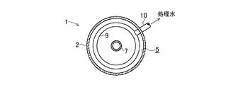
以下、図面を参照して実施の形態について説明する。図1,2は第1の実施の形態に係る凝集槽を示している。この凝集槽1は、円筒形の槽体(以下、単に槽という。)2と、該槽2の上下方向の途中に設けられた水平な仕切板3とを有し、該仕切板3の上側に急速撹拌室4が設けられ、仕切板3の下側に緩速撹拌室5が設けられている。
Hereinafter, embodiments will be described with reference to the drawings. 1 and 2 show a flocculation tank according to the first embodiment. The
急速撹拌室4内に撹拌機6が設置されている。この撹拌機6は、急速撹拌室4の軸心位置に上下方向に延設された回転軸6aと、該回転軸6aに設けられたパドル6bと、回転軸6aの上端に連結されたモータ6cとを有する。
A
仕切板3の中央部に開口3aが設けられ、この開口3aと同軸状の円筒状管部材よりなるフィードウェル7の上端が仕切板3に連結されている。フィードウェル7は緩速撹拌室5内の下部にまで延在している。フィードウェル7の下端に対面して、水平な円板状のバッフル8が設置されている。バッフル8は、複数本の細棒状の連結部材(図示略)によってフィードウェル7の下端に支持されているが、槽2に支持されてもよい。フィードウェル7の下端及びバッフル8は、緩速撹拌室5内の底部に溜ったブランケット層B内に位置する。
An
なお、バッフル8は水平な板状に限定されるものではなく、陣笠形状などのテーパ形であってもよく、それを上下逆にした形状などであってもよい。
In addition, the
緩速撹拌室5内の上部に集水管9が設けられている。この集水管9は、槽2の内周に沿って緩速撹拌室5を周回するリング状であり、その下面に多数の集水孔9aが所定間隔をおいて穿設されている。なお、集水孔9aの代りに、周方向に延在するスリットを設けてもよい。
A
集水管9に処理水取出管10の先端が接続されている。処理水取出管10は、槽2を貫通して槽2外に延出している。
The tip of the treated
槽2の底部2aは、中央側に向って下り勾配となるテーパ形である。槽2の底部2aの排泥口2bに排泥管11の上端が接続されている。排泥管11は、下部が側方に湾曲している。排泥管11は排泥バルブ(図示略)によって開閉可能とされている。
The bottom 2a of the
このように構成された凝集槽1において、原水を、原水流入管12より、槽2内の表面積負荷として好ましくは2〜30m/hで流入させる。原水としては、溶存有機物や土や砂等の濁質成分を含んでいる河川水、湖沼水、工業用水、工場からの排水等が例示されるが、これらに限定されない。
In the
原水の濁度は、通常200〜500度、特に250〜350度程度であるが、これに限定されない。 The turbidity of the raw water is usually 200 to 500 degrees, particularly about 250 to 350 degrees, but is not limited thereto.
また、原水水質に応じて、無機凝集剤好ましくはポリ塩化アルミニウム(PAC)を好ましくは200mg/L以下例えば10〜200mg/Lの濃度で薬注管13により急速撹拌室4に注入する。原水と無機凝集剤は撹拌機6によって急速に混合される。この時の撹拌強度は60〜200s−1が好ましい。滞留時間は槽2の大きさや流量を変化させることで変動可能である。凝集が不十分な場合はポリマー凝集剤を急速撹拌室4に添加する場合もある。
Further, according to the raw water quality, an inorganic flocculant, preferably polyaluminum chloride (PAC), is preferably injected into the
急速撹拌室4内にて凝集剤と十分に混合された原水は、仕切板3の開口3aからフィードウェル7を通じて、下部の緩速撹拌室5に送液される。
The raw water sufficiently mixed with the flocculant in the
フィードウェル7から下方に流出した流出水は、バッフル8と当たり、流れ方向が反転し、上昇流が生じる。
The effluent that has flowed downward from the feed well 7 hits the
急速撹拌室4内で原水が旋回しているので、フィードウェル7を下降する原水も螺旋状に旋回しながら下降する。そのため、フィードウェル7から流出し、バッフル8に当った原水は、上昇すると共に、緩速撹拌室5内にゆっくりとした旋回流を生じさせる。これにより、槽2の壁面との剪断力により、凝集が促進される。また、槽底部には粒径の大きな砂利や砂が堆積していく。また、凝集効果により生成した粗大なフロックが堆積し、ブランケット層Bが形成される。フィードウェル7から排出された原水中のフロックがこのブランケット層Bを通過する際に、フロック同士が衝突し、凝集反応が促進される。また、ブランケット層B内のフロック間の微小な隙間を処理水が通過するため、整流効果及びろ過効果も得られる。砂利、砂、凝集フロック等が分離された処理水は、集水管9から取出管10を介して取り出される。
Since the raw water swirls within the
緩速撹拌室5内の底部に砂利、砂又はブランケット層Bが過度に溜まった場合、排泥バルブを開くことにより、これらを排出し、ブランケット層Bのレベルを所定範囲に維持する。
When gravel, sand, or the blanket layer B is excessively accumulated at the bottom of the
なお、バッフル8は省略されてもよい。バッフル8が無い場合でも、粗大フロックが沈降しようとするため、ブランケット層Bが形成され、凝集促進及び濾過機能が発揮される。ただし、バッフル8を設けた場合には、バッフル8が無い場合と比較して、吐出部の面積が小さくなるため、圧力損失が生じ、撹拌エネルギーが増す。撹拌エネルギーが加わることで、凝集が促進される。また、バッフル8があることで、横方向への流れが生み出され、より強い旋回流が生み出され、緩速撹拌機能が強化される。
The
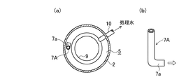
図3,4を参照して第2の実施の形態に係る凝集槽1Aについて説明する。
A
この凝集槽1Aでは、仕切板3Aの開口3a及びフィードウェル7Aが槽2の内周面近傍に位置している。フィードウェル7Aは、槽2の内周面に沿って下方に延在しており、その下端部は湾曲し、該内周面に沿って延出した流出部7aとなっている。該流出部7aはブランケット層B内に位置している。その他の構成は凝集槽1と同一であり、同一符号は同一部分を示している。
In the
この凝集槽1Aにおいても、急速撹拌室4内で凝集剤と撹拌された原水が、フィードウェル7Aを通って流出部7aから緩速撹拌室5内に槽2の内周面に沿う方向に流出する。この原水は、緩速撹拌室5内をゆっくりと旋回しながら徐々に上昇し、この間に砂利、砂、フロック等が沈殿し、処理水が集水管9及び取出管10から取り出される。
Also in the
なお、流出部7aからの流出方向は、図4(b)に示される略水平方向に限定されるものではなく、斜め上方向や斜め下方向であってもよい。また、図4(a)では、流出部7aの延在方向が槽2の内周面と略平行方向となっているが、これに限定されるものではなく、流出部7aの末端側(流出側)ほど槽2の内周面に接近するように延在してもよく、これとは逆方向に延在してもよい。
In addition, the outflow direction from the
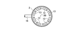
図5〜8を参照して第3の実施の形態に係る凝集槽1Bについて説明する。
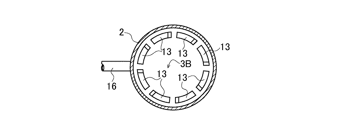
With reference to FIGS. 5-8, the
この凝集槽1Bでは、急速撹拌室4と緩速撹拌室5とを区画する仕切板3Bは、外周縁近傍に、周方向に間隔をおいて設けられた複数のスリット状の流出孔13と、各流出孔13の下側に設けられたスロープ板14とを有する。流出孔13は、槽2の内周面に沿って円弧状に延在している。
In this
流出孔13の数は、この実施の形態では8個であるが、4〜12個程度であればよい。スロープ板14は、仕切板3Bの平面図において流出孔13と重なるように周方向に延在している。スロープ板14の長手方向の一端側は、流出孔13の長手方向の一端側に接続されている。スロープ板14は、この一端側から他端側に向って下り勾配となっている。スロープ板14の長さ(槽2の周方向の長さ)は、流出孔13の長さと略同等か、又はそれよりも若干短い程度が好ましい。
Although the number of outflow holes 13 is eight in this embodiment, it may be about 4-12. The
各スロープ板14の下り勾配方向は、仕切板3Bの軸心回り方向において同一方向となっている。この実施の形態では、各スロープ板14の下り勾配方向は、仕切板3Bの軸心に対し、時計回り方向となっている。
The downward gradient direction of each
この実施の形態では、フィードウェルは設けられていない。 In this embodiment, no feed well is provided.
緩速撹拌室5内の上部の中央部には、下面が開放した集水ボックス15が設置されており、該集水ボックス15に処理水取出管16が接続されている。
A
この凝集槽1Bのその他の構成は、凝集槽1,1Aと同一であり、同一符号は同一部分を示している。
The other structure of this
この凝集槽1Bにおいては、急速撹拌室4で凝集剤が撹拌混合された原水は、各流出孔13を通り、スロープ板14に案内されて緩速撹拌室5内に旋回方向に流入し、槽2の内周面に沿って旋回しながら緩速撹拌室5内をゆっくりと下降する。緩速撹拌室5の底部に到った水は、緩速撹拌室5の中央側に集まって上昇する。この間に、砂利、砂、フロックが沈降分離され、処理水が集水ボックス15から取出管16を介して取り出される。沈殿物は、適宜排泥管11から取り出される。
In this
この凝集槽1Bでは、フィードウェル方式と異なり、ブランケット層は形成されない。この凝集槽1Bでは、上部の急速撹拌室4からの水流がスロープ板14に沿って流れることにより、高い撹拌強度を持った旋回流が生み出され、その撹拌力により凝集フロックの成長が促進される。
In this
上記実施の形態は、いずれも本発明の一例であり、本発明は図示以外の形態とされてもよい。例えば、図3,4の凝集槽1Aにおいて、フィードウェル7Aを複数本設け、各フィードウェル7Aから同一周方向(例えば、平面図において時計方向)に原水を流出させるようにしてもよい。
Each of the above embodiments is an example of the present invention, and the present invention may be configured other than illustrated. For example, in the
本発明では、緩速撹拌室5内の上部に浮上濾材を配置し、集水管9又は集水ボックス15を浮上濾材層内に位置させ、緩速撹拌室5内の水が浮上濾材で濾過された後、集水管9又は集水ボックス15に流入するようにしてもよい。
In the present invention, the floating filter medium is disposed in the upper part of the
本発明装置の後段に加圧浮上装置、砂ろ過装置、膜処理などを組み合わせて、さらに処理することも可能である。 Further processing can be performed by combining a pressure flotation device, a sand filtration device, a membrane treatment and the like in the subsequent stage of the device of the present invention.
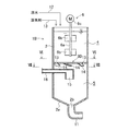
[実施例1]
図1に示す凝集槽を円筒半径150mmのカラムにより構成した。急速撹拌室4の高さを1250mm、緩速撹拌室5の高さを1250mmとし、急速撹拌室4には縦50mm、横100mmの長方形の撹拌翼が2枚付いた撹拌機6を設置した。このカラムを満水にした状態において、カラム上部より、水道水をポンプで流量256L/hとなるように送水した。この水道水に対して、ポリ塩化アルミニウム(PAC)の濃度が120mg/LとなるようにPACを添加した。この時、撹拌機の回転数を100rpmとした。
[Example 1]
The agglomeration tank shown in FIG. 1 was constituted by a column having a cylindrical radius of 150 mm. The height of the
この急速撹拌室4に対し、赤玉土の濃度が300mg/Lとなるように、赤玉土懸濁溶液を添加した。以後、30秒ごとに、流入した水道水量に対し、赤玉土濃度300mg/Lとなるように、赤玉土懸濁液を添加した。
To this
上記の試験条件の場合、上部撹拌槽の滞留時間が5分、下部撹拌槽の滞留時間が5分となるので、水が入れ替わる時間の2倍の時間として試験開始20分後の処理水を採取し、濁度を測定した。結果を表1に示す。 In the case of the above test conditions, the residence time in the upper agitation tank is 5 minutes and the residence time in the lower agitation tank is 5 minutes, so that the treated water 20 minutes after the start of the test is collected as twice the time that the water is replaced. The turbidity was measured. The results are shown in Table 1.
赤球土以外に、鹿沼土、黒土を添加し、同試験条件での処理を行った。なお、黒土添加時は原水SSを600mg/Lとした。結果を表1に示す。 In addition to red ball soil, Kanuma soil and black soil were added, and the treatment was performed under the same test conditions. In addition, the raw water SS was 600 mg / L at the time of black soil addition. The results are shown in Table 1.
上記処理の結果、いずれの土を添加した場合も、300mg/L以上の濁質成分(SS)を含む原水が、6度程度の濁度となって排出されることが認められた。 As a result of the above treatment, it was confirmed that when any soil was added, the raw water containing 300 mg / L or more of the turbid component (SS) was discharged with a turbidity of about 6 degrees.
1,1A,1B 凝集槽
2 槽
3,3A,3B 仕切板
4 急速撹拌室
5 緩速撹拌室
6 撹拌機
7,7A フィードウェル
8 バッフル
9 集水管
13 流出孔
14 スロープ板
15 集水ボックス
1, 1A,
Claims (8)
上側の室は、撹拌機を備えた急速撹拌室であり、
下側の室は、該急速撹拌室からの移流によって旋回流が生じる緩速撹拌室であり、
該緩速撹拌室の上部に処理水取出用集水部材が設けられており、
該緩速撹拌室の底部に排泥口が設けられていることを特徴とする凝集槽。 The inside of the tank is divided into at least two upper and lower chambers by a partition plate, raw water is supplied to the upper chamber, and is a coagulation tank that is transferred from the upper chamber to the lower chamber by the advection means,
The upper chamber is a rapid stirring chamber with a stirrer,
The lower chamber is a slow stirring chamber in which a swirling flow is generated by advection from the rapid stirring chamber,
A water collecting member for removing treated water is provided at the upper part of the slow stirring chamber,
A coagulation tank characterized in that a drainage port is provided at the bottom of the slow stirring chamber.
前記仕切板の周縁部に連なり、下方に延在したフィードウェルを備えており、
該フィードウェルの下端部に、槽の内周面に沿って水を流出させる流出部が設けられていることを特徴とする凝集槽。 The advection means according to claim 1,
Continuing to the peripheral edge of the partition plate, comprising a feed well extending downward,
An agglomeration tank characterized in that an outflow part for allowing water to flow out along the inner peripheral surface of the tank is provided at the lower end of the feed well.
前記仕切板の周縁部に、周方向に間隔をおいて設けられた複数個の流出孔と、
該流出孔を通って緩速撹拌室に流入する水を旋回方向に導くためのスロープ板と
を有することを特徴とする凝集槽。 The advection means according to claim 1,
A plurality of outflow holes provided at intervals in the circumferential direction on the peripheral edge of the partition plate;
And a slope plate for guiding water flowing into the slow stirring chamber through the outflow hole in a swirling direction.
前記急速撹拌室に原水及び凝集剤を供給して急速撹拌機によって撹拌し、
該急速撹拌室から緩速撹拌室を経て前記集水部材に到った水を処理水として取り出すことを特徴とする凝集処理方法。 A flocculation treatment method using the flocculation tank according to any one of claims 1 to 6,
Supply the raw water and flocculant to the rapid stirring chamber and stir with a rapid stirrer,
A coagulation treatment method characterized in that water reaching the water collecting member is taken out as treated water from the rapid stirring chamber through a slow stirring chamber.
前記緩速撹拌室内の底部にブランケット層が形成されており、
前記急速撹拌室に原水及び凝集剤を供給して急速撹拌機によって撹拌し、
該急速撹拌室内の水をフィードウェルによって緩速撹拌室内の底部のブランケット層内に導き、
該ブランケット層を通過し緩速撹拌室内を上昇して前記集水部材に到った水を処理水として取り出すことを特徴とする凝集処理方法。 A flocculation treatment method using the flocculation tank according to any one of claims 2 to 4,
A blanket layer is formed at the bottom of the slow stirring chamber,
Supply the raw water and flocculant to the rapid stirring chamber and stir with a rapid stirrer,
Water in the rapid stirring chamber is guided by a feed well into a blanket layer at the bottom of the slow stirring chamber;
A coagulation treatment method characterized in that water that passes through the blanket layer and rises in the slow stirring chamber and reaches the water collecting member is taken out as treated water.
Priority Applications (1)
| Application Number | Priority Date | Filing Date | Title |
|---|---|---|---|
| JP2015135335A JP2017013029A (en) | 2015-07-06 | 2015-07-06 | Flocculation tank and flocculation treatment method |
Applications Claiming Priority (1)
| Application Number | Priority Date | Filing Date | Title |
|---|---|---|---|
| JP2015135335A JP2017013029A (en) | 2015-07-06 | 2015-07-06 | Flocculation tank and flocculation treatment method |
Publications (1)
| Publication Number | Publication Date |
|---|---|
| JP2017013029A true JP2017013029A (en) | 2017-01-19 |
Family
ID=57828670
Family Applications (1)
| Application Number | Title | Priority Date | Filing Date |
|---|---|---|---|
| JP2015135335A Pending JP2017013029A (en) | 2015-07-06 | 2015-07-06 | Flocculation tank and flocculation treatment method |
Country Status (1)
| Country | Link |
|---|---|
| JP (1) | JP2017013029A (en) |
Cited By (3)
| Publication number | Priority date | Publication date | Assignee | Title |
|---|---|---|---|---|
| CN108046397A (en) * | 2017-12-27 | 2018-05-18 | 山东佳星环保科技有限公司 | Continuous separated sewage disposal subsider |
| KR101877918B1 (en) * | 2018-04-11 | 2018-07-12 | 주식회사 장산이엔지 | advanced water treating apparatus |
| JP2021186745A (en) * | 2020-05-29 | 2021-12-13 | 水ing株式会社 | Coagulation membrane filtration system and coagulation membrane filtration method |
-
2015
- 2015-07-06 JP JP2015135335A patent/JP2017013029A/en active Pending
Cited By (5)
| Publication number | Priority date | Publication date | Assignee | Title |
|---|---|---|---|---|
| CN108046397A (en) * | 2017-12-27 | 2018-05-18 | 山东佳星环保科技有限公司 | Continuous separated sewage disposal subsider |
| CN108046397B (en) * | 2017-12-27 | 2023-06-16 | 山东佳星环保科技有限公司 | Continuous separation sedimentation tank for sewage treatment |
| KR101877918B1 (en) * | 2018-04-11 | 2018-07-12 | 주식회사 장산이엔지 | advanced water treating apparatus |
| JP2021186745A (en) * | 2020-05-29 | 2021-12-13 | 水ing株式会社 | Coagulation membrane filtration system and coagulation membrane filtration method |
| JP7403387B2 (en) | 2020-05-29 | 2023-12-22 | 水ing株式会社 | Coagulation membrane filtration system and coagulation membrane filtration method |
Similar Documents
| Publication | Publication Date | Title |
|---|---|---|
| CA2767093C (en) | Method and apparatus for treating well flow-back and produced water or other wastewater | |
| KR100810334B1 (en) | Coagulating and separating apparatus | |
| CN109368875B (en) | Sewage filtering treatment device for removing suspended matters in water body and treatment method thereof | |
| KR101673668B1 (en) | A Circular sludge collector | |
| KR101820864B1 (en) | dissolved air flotation type pretreatment device built-in fiber ball and water treatment methods using the same | |
| KR101961299B1 (en) | A Multistage hydro-cyclone for rapid collection of weighted coagulation additives from mixed sludge | |
| CN109364575B (en) | Multistage filtering system for sewage treatment and sewage filtering method | |
| KR101278958B1 (en) | Waste water treatment system | |
| CN105936531A (en) | Induced crystallization and deposition water treatment equipment | |
| JP6067268B2 (en) | Water treatment system | |
| KR101999229B1 (en) | The intregrated direct filtration process with coagulation and flocculation for phosphorus removal | |
| EP3221269A1 (en) | Improved ballasted clarification system | |
| JPH11169609A (en) | Flocculating and settling apparatus | |
| JP2017013029A (en) | Flocculation tank and flocculation treatment method | |
| KR101658044B1 (en) | Advanced treatment apparatus | |
| EP3090793B1 (en) | Media filter comprising a coagulation/flocculation multi-step | |
| US3481868A (en) | Water clarifier and water clarification method | |
| JP2006043626A (en) | Water treatment apparatus | |
| JP2004008909A (en) | Flocculating and settling method and apparatus | |
| JP2002239306A (en) | Floc forming device, solid-liquid separation apparatus and wastewater treatment method | |
| KR101077248B1 (en) | Solid and liquid separator using micro bubble | |
| JP2000117005A (en) | Flocculating and settling method and device | |
| KR101694919B1 (en) | Powerless mixing flocculation tank and dissolved air flotation device using the same | |
| JP2017159213A (en) | Flocculation treatment method and apparatus | |
| JPH08961Y2 (en) | Solid-liquid separator for raw water such as sludge water equipped with line mixer |