JP2017007633A - Steering device and switching method of traveling mode of vehicle - Google Patents
Steering device and switching method of traveling mode of vehicle Download PDFInfo
- Publication number
- JP2017007633A JP2017007633A JP2015145034A JP2015145034A JP2017007633A JP 2017007633 A JP2017007633 A JP 2017007633A JP 2015145034 A JP2015145034 A JP 2015145034A JP 2015145034 A JP2015145034 A JP 2015145034A JP 2017007633 A JP2017007633 A JP 2017007633A
- Authority
- JP
- Japan
- Prior art keywords
- wheel
- knuckle
- vehicle
- steering
- kingpin
- Prior art date
- Legal status (The legal status is an assumption and is not a legal conclusion. Google has not performed a legal analysis and makes no representation as to the accuracy of the status listed.)
- Pending
Links
Images


Landscapes
- Steering-Linkage Mechanisms And Four-Wheel Steering (AREA)
Abstract
Description
この発明は、通常走行モードとその場回転等の特殊走行モードとの間で走行モードを切り替え可能としたステアリング装置、及び、車両の走行モードの切り替え方法に関する。 The present invention relates to a steering device capable of switching a traveling mode between a normal traveling mode and a special traveling mode such as on-site rotation, and a method for switching a traveling mode of a vehicle.
左右の車輪(以下、タイヤ、ホイール、ハブ、インホイールモータ等を含めて総合的に「車輪」と称する。)を結ぶステアリングリンク機構を用いて車輪を転舵するものに、アッカーマン・ジャントウ式と呼ばれるステアリング装置がある。このステアリング装置は、タイロッドとナックルアームを有し、車両の回転時に、左右の車輪が同一回転中心をもつように作用する。 Ackerman-Jantou type is used to steer the wheels using a steering link mechanism that connects the left and right wheels (hereinafter collectively referred to as "wheels" including tires, wheels, hubs, in-wheel motors, etc.) There is a steering device called. This steering device has a tie rod and a knuckle arm, and acts so that the left and right wheels have the same center of rotation when the vehicle rotates.
このステアリング装置として、例えば、特許文献1に示す構成のものがある。このステアリング装置は、タイロッドとナックルアームを用いる左右車輪のステアリングリンク機構を前輪側または後輪側の少なくとも一方に備え、タイロッド長さ、左右のタイロッド間距離、又は各車輪とナックルアームのなす角度のいずれかを変化させるアクチュエータを設けることで、通常走行、平行移動、小回りのすべての走行をスムーズに行うとともに、優れた応答性を確保している。
As this steering apparatus, there exists a thing of the structure shown in
特許文献2に示すステアリング装置は、前後輪の左右車輪間に配置され、軸心周りに回転可能なステアリングシャフトと、このステアリングシャフトを左右2分割した間に、分割されたステアリングシャフトの回転方向を正逆方向で切り替える正逆切り替え手段を備えている。この切り替え手段によって、舵角90度、横方向移動等を可能としている。 The steering device shown in Patent Document 2 is arranged between the left and right wheels of the front and rear wheels, and can rotate around the axis, and the rotation direction of the divided steering shaft can be divided between the left and right divided steering shafts. Forward / reverse switching means for switching in the forward / reverse direction is provided. This switching means enables a steering angle of 90 degrees, lateral movement, and the like.
特許文献3には、前輪の転舵に応じてアクチュエータが作動して、後輪を転舵するようにした4輪転舵車両の技術について示されている。また、特許文献4には、左右車輪間を結ぶラックハウジングを前後方向に移動させることで、左右車輪のトー調整を行い、走行安定性を高めたステアリング装置の技術について示されている。
Patent Document 3 discloses a technique of a four-wheel steered vehicle in which an actuator is operated in accordance with the steering of the front wheels to steer the rear wheels. Further,
一般的なアッカーマン・ジャントウ式のステアリングリンク機構によれば、通常走行時には、各車輪の回転ライン(車輪の幅方向中心線)から平面視垂直に延びた線が、車両の回転中心に集まるので、スムーズな走行ができる。しかし、車両の横方向移動(車両が前後方向を向いた状態での横方向への平行移動)を求める場合、車輪を前後方向に対して90度の方向に操舵することは、ステアリングリンクの長さや他部材との干渉から困難である。また、仮に、左右の車輪のうち一方の車輪を90度に操舵した場合でも、他方の車輪は一方の車輪と完全に平行にはならず、スムーズな走行が困難である。 According to a general Ackermann-Jantou type steering link mechanism, during normal driving, lines extending vertically from the rotation line of each wheel (the center line in the width direction of the wheel) gather in the center of rotation of the vehicle. Smooth running is possible. However, when the lateral movement of the vehicle (transverse movement in the lateral direction with the vehicle facing in the front-rear direction) is obtained, steering the wheel in a direction of 90 degrees with respect to the front-rear direction is a problem with the length of the steering link. It is difficult to interfere with other members. Further, even if one of the left and right wheels is steered at 90 degrees, the other wheel is not completely parallel to the one wheel, and smooth running is difficult.
また、この種の車両では、通常、主転舵車輪である前輪を車両の所定の進行方向に転舵し、従転舵車輪である後輪は、車両の前後方向と平行を保つように設計されている。このため、この車両の前輪を転舵し回転させたときに、前輪と後輪の回転中心が同一位置とならない。このため、低車速時には内輪差により後輪が回転円の内側に入る姿勢で車両が回転し、高車速時には遠心力により前輪が回転円の内側に入る姿勢で車両が回転することになる。すなわち、前輪を車両の進行方向である回転方向に転舵しても、車両の姿勢を回転方向に一致させ操向することができないという問題がある。そこで、前輪のみならず後輪をも転舵することにより、走行性を向上させる4輪ステアリング装置を有する車両がある。 Also, in this type of vehicle, the front wheels, which are the main steered wheels, are usually steered in a predetermined traveling direction of the vehicle, and the rear wheels, which are the follower steered wheels, are designed to be parallel to the longitudinal direction of the vehicle. Has been. For this reason, when the front wheel of this vehicle is steered and rotated, the rotation center of the front wheel and the rear wheel is not at the same position. For this reason, at low vehicle speeds, the vehicle rotates in a posture in which the rear wheels enter the inside of the rotation circle due to the inner wheel difference, and at high vehicle speeds, the vehicles rotate in a posture in which the front wheels enter the inside of the rotation circle by centrifugal force. That is, there is a problem that even if the front wheels are steered in the rotational direction that is the traveling direction of the vehicle, it is not possible to steer the vehicle so that the posture of the vehicle coincides with the rotational direction. Therefore, there is a vehicle having a four-wheel steering device that improves traveling performance by turning not only front wheels but also rear wheels.
4輪ステアリング装置を有する車両(所謂4WS車)として、例えば、特許文献1に記載の技術では、車両の横方向移動、小回り等が可能である。しかし、タイロッドの長さ、左右タイロッド間の距離、あるいは、車輪とナックルアームのなす角を変化させるために多くのアクチュエータを備え、各アクチュエータの複雑な制御が必要となる。また、特許文献2に記載の技術は、その機構上、構造が複雑であって、ラックバーの回転で車輪を転舵するために、多数の歯車を使用している。このため、各歯車間にガタが発生しやすく、円滑に車輪の転舵をすることが困難である。
As a vehicle having a four-wheel steering device (a so-called 4WS vehicle), for example, the technique described in
また、特許文献3の技術は、従来の4輪ステアリング装置の一例であって後輪転舵を可能としているが、この機構だけでは横方向移動は困難である。さらに、特許文献4の技術は、トー調整が可能である反面、車両の横方向移動、小回り等には対応できないという問題がある。
Moreover, although the technique of patent document 3 is an example of the conventional four-wheel steering apparatus and enables rear-wheel steering, lateral movement is difficult only with this mechanism. Furthermore, the technique of
特許文献1から4に記載のステアリング装置の諸問題を解決すべく、本願の発明者は、特許文献5に示すように、左右反対方向に移動可能な2つのラックバーを持ち、前記ラックバーのそれぞれを左右いずれかの車輪にタイロッドを介して接続し、同期ギアボックスに保持される同期ギアにより、同期ギアボックスに対して、前記ラックバーを反対方向に移動可能としたステアリング装置を発明した。この2つのラックバーには、このラックバーに噛み合うピニオンギアがそれぞれ設けられ、両ピニオンギアの間には、両ピニオンギアの回転軸を結合又は分離可能とする連結機構が設けられている。この連結機構を結合すると、両ラックバーを一体として同方向に同距離移動する、すなわち、左右の車輪を同方向に転舵することができる。その一方で、この連結機構を分離すると、両ラックバーを反対方向に同距離移動する、すなわち、左右の車輪を逆方向に転舵することができる。
In order to solve the problems of the steering devices described in
ここで、左右の車輪を同方向に転舵することは、一般の車両における通常の転舵に相当する。また、左右の車輪を逆方向に転舵することは、通常走行モードからその場回転、横方向移動等の特殊走行モードへの走行モードの切り替えに相当する。この通常の転舵、及び走行モードの切り替えは、いずれもタイロッドを介して、各車輪に設けられたナックルの一本のキングピン軸周りの回動として車輪側に伝達される。このステアリング装置を車両に搭載すれば、その場回転や横方向移動等の特殊走行モードを行うことができるとともに、通常走行モードから特殊走行モードへの変更もスムーズに行うことができる。 Here, turning the left and right wheels in the same direction corresponds to normal turning in a general vehicle. Further, turning the left and right wheels in the reverse direction corresponds to switching the travel mode from the normal travel mode to a special travel mode such as spot rotation or lateral movement. Both the normal turning and the switching of the traveling mode are transmitted to the wheel side through a tie rod as a rotation around one kingpin axis of a knuckle provided on each wheel. If this steering device is mounted on a vehicle, a special travel mode such as in-situ rotation and lateral movement can be performed, and a change from the normal travel mode to the special travel mode can be performed smoothly.
特許文献5に係るステアリング装置は、左右の車輪を左右同方向及び逆方向のいずれの方向にも転舵可能としたものであって、複雑なギア機構を備えている。このため、ステアリング装置が大重量となるとともに製造コストが増大する等の、解決すべき幾つかの問題を抱えていた。 The steering device according to Patent Document 5 enables the left and right wheels to be steered in both the left and right directions and the reverse direction, and includes a complicated gear mechanism. For this reason, the steering device has several problems to be solved such as an increase in weight and an increase in manufacturing cost.
そこで、この発明は、簡便な装置構成で、通常走行モードから特殊走行モードへの切り替えを行うことを課題とする。 Accordingly, an object of the present invention is to switch from the normal travel mode to the special travel mode with a simple device configuration.
この課題を解決するために、この発明においては、懸架装置を介してシャーシに設けられたナックルと、前記懸架装置に対し、前記ナックルを転舵方向に回動する第一のキングピン軸と、前記ナックルに対し、車輪を車両の各走行モードに対応する角度に回動する第二のキングピン軸と、前記第一のキングピン軸周りに前記車輪を左右同方向に転舵可能な転舵装置と、前記第二のキングピン軸周りの前記車輪の回動を、前記各走行モードに対応する位置でロック可能なロック機構と、を備えたステアリング装置を構成した。 In order to solve this problem, in the present invention, a knuckle provided in a chassis via a suspension device, a first kingpin shaft for rotating the knuckle in a steering direction with respect to the suspension device, With respect to the knuckle, a second kingpin shaft that rotates the wheel to an angle corresponding to each driving mode of the vehicle, and a steering device that can steer the wheel in the same direction left and right around the first kingpin shaft, A steering device is provided that includes a lock mechanism that can lock the rotation of the wheel around the second kingpin axis at a position corresponding to each travel mode.
このように、キングピン軸を第一のキングピン軸と第二のキングピン軸に分けて構成することにより、第一のキングピン軸を通常の転舵に関与させる一方で、第二のキングピン軸を走行モードの切り替えに関与させることができる。この場合、ステアリング装置のタイロッドを第一のキングピン軸側に連結して、ステアリング装置に通常の転舵のみを担わせればよいので、このステアリング装置の転舵装置として、一般的に用いられる構成が簡便なラックアンドピニオン式のものを採用することができる。このため、ステアリング装置の重量低減や製造コスト削減を図ることができるとともに、車両への搭載性も向上することができる。なお、第一のキングピン軸及び第二のキングピン軸は、実際に軸体を備えた構成、又は実際に軸体を有さず所定の回転軸周りに回動する構成のいずれの構成であってもよい。 In this way, by dividing the kingpin axis into the first kingpin axis and the second kingpin axis, the first kingpin axis is involved in normal steering while the second kingpin axis is in the travel mode. Can be involved in switching. In this case, since the tie rod of the steering device is connected to the first kingpin shaft side and the steering device only has to perform normal steering, the configuration generally used as the steering device of this steering device is A simple rack and pinion type can be employed. For this reason, while being able to aim at the weight reduction and manufacturing cost reduction of a steering apparatus, the mounting property to a vehicle can also be improved. The first kingpin shaft and the second kingpin shaft are either of a configuration that actually includes a shaft body or a configuration that does not actually have a shaft body and rotates around a predetermined rotation axis. Also good.
また、ロック機構を設け、第二のキングピン軸周りの回転をロック状態とした上で、ステアリング操作を行うことにより、各走行モードにおける左右の車輪の転舵角の調節を行うことができる。さらに、第二のキングピン軸周りの回転をロック解除状態とした上でステアリング操作を行うことにより、車輪を路面との間の摩擦によって転舵できない状態としたままナックルを第二のキングピン軸周りに回転して、走行モードの切り替えを行うことができる。 Further, by providing a lock mechanism and setting the rotation around the second kingpin axis in a locked state, the steering angle can be adjusted to adjust the turning angle of the left and right wheels in each travel mode. Furthermore, by turning the rotation around the second kingpin axis and performing the steering operation, the knuckle is moved around the second kingpin axis while the wheel cannot be steered by friction with the road surface. It can rotate and can switch a driving mode.
前記構成においては、前記第二のキングピン軸周りに前記車輪を転舵させる駆動源を前後の前記車輪の少なくとも一方にさらに備えた構成とするのが好ましい。このように、駆動源を設けることにより、走行モードの切り替えに駆動源による駆動力を併用することができ、一層スムーズに走行モードの切り替えを行うことができる。 In the above configuration, it is preferable that a drive source for turning the wheel around the second kingpin axis is further provided in at least one of the front and rear wheels. Thus, by providing the drive source, the driving force by the drive source can be used in combination with the switching of the travel mode, and the travel mode can be switched more smoothly.
前記各構成においては、前記第二のキングピン軸のスクラブ半径が、前記第一のキングピン軸のスクラブ半径よりも大きくなるように、前記第一のキングピン軸及び前記第二のキングピン軸を配置した構成とするのが好ましい。 In each of the above configurations, the first kingpin shaft and the second kingpin shaft are arranged so that the scrub radius of the second kingpin shaft is larger than the scrub radius of the first kingpin shaft. Is preferable.
スクラブ半径は、キングピン軸が地面と交わる点と、タイヤの接地面中心との間の距離であり、キングピン軸の位置や傾きとともに、このスクラブ半径の大きさが車両の走行特性や転舵特性に大きな影響を与える。具体的には、スクラブ半径を大きくすると、走行モードの切り替え特性は向上する一方で、車両の走行特性が悪化することがある。上記のように、キングピン軸を第一のキングピン軸と第二のキングピン軸で別々に構成し、第一のキングピン軸を車輪の転舵操作用、第二のキングピン軸を走行モードの切り替え用としてそれぞれ機能させることにより、走行特性の確保と、走行モードの切り替え特性の確保の両立を図ることができる。 The scrub radius is the distance between the point at which the kingpin axis intersects the ground and the center of the tire's ground contact surface. The scrub radius, along with the position and inclination of the kingpin axis, affects the vehicle's running characteristics and turning characteristics. It has a big impact. Specifically, when the scrub radius is increased, the driving mode switching characteristics are improved, while the vehicle driving characteristics may be deteriorated. As described above, the kingpin shaft is composed of the first kingpin shaft and the second kingpin shaft separately, the first kingpin shaft is used for the wheel steering operation, and the second kingpin shaft is used for switching the traveling mode. By making each function function, it is possible to achieve both ensuring of traveling characteristics and ensuring of switching characteristics of traveling modes.
前記各構成においては、前記駆動源が、前記車輪に設けられたインホイールモータ、油圧シリンダ、空圧シリンダ、電動シリンダ、又は、モータと減速機の組み合わせのいずれかとすることができる。 In each said structure, the said drive source can be either an in-wheel motor provided in the said wheel, a hydraulic cylinder, a pneumatic cylinder, an electric cylinder, or the combination of a motor and a reduction gear.
また、この発明においては、懸架装置を介してシャーシに設けられたナックルに、前記懸架装置に対し、前記ナックルを転舵方向に回動させる第一のキングピン軸と、前記ナックルに対し、車輪を車両の走行モードに対応する方向に回動させる第二のキングピン軸を設けるとともに、前記第二のキングピン軸周りの前記車輪の回動を、前記車両が採り得る各走行モードに対応する位置でロック可能なロック機構を設け、前記ロック機構をロック状態とした上で、前記ナックルに連結された左右の前記車輪を左右同方向に転舵可能な転舵装置を駆動し、前記ナックルを前記第一のキングピン軸周りに回動して車輪を転舵する車輪転舵ステップと、前記ロック機構をロック解除状態とした上で、前記ナックルに連結された前記転舵装置を駆動し、前記車輪と路面との間の摩擦によってこの車輪の転舵を防止しつつ、前記ナックルを前記第一のキングピン軸周り及び前記第二のキングピン軸周りに回動して走行モードを切り替える、第一走行モード切替ステップと、を交互に又はいずれか一方を行うことにより車両の走行モードを切り替える車両の走行モードの切り替え方法を構成した。 In the present invention, a knuckle provided on the chassis via the suspension device is provided with a first kingpin shaft for rotating the knuckle in a steering direction with respect to the suspension device, and a wheel with respect to the knuckle. A second kingpin shaft that rotates in a direction corresponding to the travel mode of the vehicle is provided, and the rotation of the wheel around the second kingpin shaft is locked at a position corresponding to each travel mode that the vehicle can take. A lock mechanism capable of turning the left and right wheels connected to the knuckle in the same direction, and driving the steering device to the first knuckle. A wheel turning step for turning the wheel by turning around the kingpin axis, and driving the turning device connected to the knuckle after the lock mechanism is in an unlocked state, The first knuckle is rotated around the first kingpin axis and the second kingpin axis to prevent the wheel from being turned by friction between the wheel and the road surface, and the driving mode is switched. A vehicle driving mode switching method for switching the vehicle driving mode by alternately or any one of the driving mode switching step is configured.
この走行モードの切り替え方法によると、左右の車輪を左右同方向に転舵する一般的な転舵装置を用いて、車両の走行モードを通常走行モードから横方向移動モード等の特殊走行モードに容易に切り替えることができ、上述したように、ステアリング装置の重量低減や製造コスト削減を図ることができるとともに、車両への搭載性も向上することができる。 According to this travel mode switching method, the vehicle travel mode can be easily changed from the normal travel mode to the special travel mode such as the lateral travel mode using a general steering device that steers the left and right wheels in the same direction. As described above, the weight of the steering device and the manufacturing cost can be reduced, and the mounting property on the vehicle can be improved.
前記ロック機構をロック解除状態とした上で、前記転舵装置を固定状態とし、前記車輪を駆動源で駆動することによって、前記ナックルを前記第二のキングピン軸周りに回動して、走行モードを切り替える、第二走行モード切替ステップをさらに備えた構成とするのが好ましい。このように、走行モードの切り替えに駆動源による駆動力を併用することにより、走行モードの切り替えを一層スムーズに行うことができる。 The lock mechanism is in an unlocked state, the steered device is in a fixed state, and the wheels are driven by a drive source to rotate the knuckle around the second kingpin axis, thereby driving mode It is preferable to further include a second traveling mode switching step. As described above, the driving mode can be switched more smoothly by using the driving force of the driving source together with the switching of the driving mode.
前記切り替え方法においても、前記駆動源が、前記車輪に設けられたインホイールモータ、油圧シリンダ、空圧シリンダ、電動シリンダ、又は、モータと減速機の組み合わせのいずれかとすることができる。 Also in the switching method, the drive source can be any of an in-wheel motor, a hydraulic cylinder, a pneumatic cylinder, an electric cylinder, or a combination of a motor and a speed reducer provided on the wheel.
この発明においては、懸架装置を介してシャーシに設けられたナックルと、前記懸架装置に対し、前記ナックルを転舵方向に回動する第一のキングピン軸と、前記ナックルに対し、車輪を車両の各走行モードに対応する角度に回動する第二のキングピン軸と、前記第一のキングピン軸周りに前記車輪を左右同方向に転舵可能な転舵装置と、前記第二のキングピン軸周りの前記車輪の回動を、前記各走行モードに対応する位置でロック可能なロック機構と、を備えたステアリング装置を構成した。 In the present invention, a knuckle provided on the chassis via a suspension device, a first kingpin shaft for rotating the knuckle in a steering direction with respect to the suspension device, and a wheel for the knuckle A second kingpin shaft that rotates at an angle corresponding to each travel mode, a steering device that can steer the wheels in the same direction left and right around the first kingpin shaft, and a second kingpin shaft A steering device is provided that includes a lock mechanism that can lock the rotation of the wheel at a position corresponding to each travel mode.
このように、キングピン軸を第一のキングピン軸と第二のキングピン軸に分けて構成することにより、第一のキングピン軸を通常の転舵に関与させる一方で、第二のキングピン軸を走行モードの切り替えに関与させることができる。この場合、ステアリング装置のタイロッドを第一のキングピン軸側に連結して、ステアリング装置に通常の転舵のみを担わせればよいので、このステアリング装置の転舵装置として、構成が簡便であって一般的に用いられるラックアンドピニオン式のものを採用することができる。このため、その構成を簡便化して、装置重量や製造コストの増大等の問題を回避できるとともに、車両への搭載性も向上することができる。 In this way, by dividing the kingpin axis into the first kingpin axis and the second kingpin axis, the first kingpin axis is involved in normal steering while the second kingpin axis is in the travel mode. Can be involved in switching. In this case, it is only necessary to connect the tie rod of the steering device to the first kingpin shaft side so that the steering device bears only normal steering. A rack-and-pinion type that is commonly used can be employed. For this reason, the structure can be simplified, problems such as an increase in apparatus weight and manufacturing cost can be avoided, and mounting on a vehicle can be improved.
さらに、ロック機構を設け、第二のキングピン軸周りの回転をロック状態とした上でステアリング操作を行うことにより、各走行モードにおける左右の車輪の転舵角の調節を行うことができる。また、第二のキングピン軸周りの回転をロック解除状態とした上でステアリング操作を行うことにより、車輪を路面との間の摩擦によって転舵できない状態としたままナックルを第二のキングピン軸周りに回転して、走行モードの切り替えを行うことができる。 Further, by providing a lock mechanism and performing the steering operation after setting the rotation around the second kingpin axis to the locked state, the turning angle of the left and right wheels in each travel mode can be adjusted. In addition, by turning the rotation around the second kingpin axis and performing the steering operation, the knuckle is moved around the second kingpin axis while the wheel cannot be steered by friction with the road surface. It can rotate and can switch a driving mode.
この発明に係るステアリング装置の構成、このステアリング装置を搭載した車両C(図4参照)の走行モードの切り替え方法、及びこの車両Cの各走行モードについて順に説明する。 The configuration of the steering device according to the present invention, the method for switching the traveling mode of the vehicle C (see FIG. 4) on which the steering device is mounted, and each traveling mode of the vehicle C will be described in order.
(1)ステアリング装置の構成について
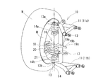
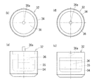
この発明に係るステアリング装置の第一実施形態を図1及び図2に、第二実施形態を図3に示す。図1(a)は正面図、(b)は側面図、図2は斜視図、図3(a)は正面図、(b)は平面図、(c)は側面図、(d)は斜視図である。第一実施形態に係るステアリング装置10は、車輪w内に駆動源(本実施形態ではインホイールモータM)を備えた駆動輪側に採用され、第二実施形態に係るステアリング装置30は、駆動源を備えていない従動輪側に採用される。以下においては、第一実施形態に係るステアリング装置10を駆動輪用ステアリング装置(以下において、符号10を付する)と、第二実施形態に係るステアリング装置30を従動輪用ステアリング装置(以下において、符号30を付する)とそれぞれ称する。
(1) Configuration of Steering Device FIG. 1 and FIG. 2 show a first embodiment of a steering device according to the present invention, and FIG. 3 shows a second embodiment. 1 (a) is a front view, (b) is a side view, FIG. 2 is a perspective view, FIG. 3 (a) is a front view, (b) is a plan view, (c) is a side view, and (d) is a perspective view. FIG. The
これらのステアリング装置10、30は、例えば、図4に示す車両Cに採用される。この車両Cは、2人乗車(横並び二人乗り)の超小型モビリティである。なお、この発明に係るステアリング装置10、30の用途は、この超小型モビリティに限定されるものではなく、通常の車両にも適用することができる。この車両Cの後輪RR、RLはインホイールモータMが設けられた駆動輪であり、前輪FR、FLはインホイールモータMが設けられていない従動輪である。
These
すなわち、図5に示すように、後輪RR、RL側には駆動輪用ステアリング装置10が設けられ、前輪FR、FL側には従動輪用ステアリング装置30が設けられている。駆動輪用ステアリング装置10は、運転者の走行モードの切り替え等の操作に基づいて転舵を行うステアバイワイヤ方式が採用される一方で、従動輪用ステアリング装置30は、運転者のステアリング1の操作に基づいて転舵を行う、通常のラックアンドピニオン方式が採用されている。
That is, as shown in FIG. 5, a driving
駆動輪用ステアリング装置10は、図1及び図2に示すように、懸架装置11(アッパーアーム11a、ロワアーム11b)を介して、例えば、図4に示す車両Cのシャーシ(図示せず)に設けられたナックル12と、懸架装置11に対し、ナックル12を転舵方向に回動させる第一のキングピン軸13と、ナックル12に対し、車輪wを車両Cの各走行モードに対応する方向に回動させる第二のキングピン軸14と、第一のキングピン軸13周りに車輪wを左右同方向に転舵可能な転舵装置15(図5参照)と、第二のキングピン軸14周りの車輪wの回動を、前記各走行モードに対応する位置でロック可能なロック機構16と、をその基本構成とする。なお、車両Cの各種走行モードに対応する車輪wの転舵方向については、項目(3)で詳しく説明する。
As shown in FIGS. 1 and 2, the drive
ナックル12は、このナックル12の上下端部に回動軸13a、13bを有する第一のキングピン軸13の周りに回動可能にタイロッド17に接続されている。このタイロッド17は、車輪wを転舵する転舵装置15(図5等参照)に接続されている。転舵装置15を駆動してタイロッド17を移動させることにより、ナックル12を第一のキングピン軸13周りに回動して、車輪wを転舵することができる。なお、ナックル12のタイロッド17との接続部分の形状は、このナックル12を取り付ける車輪wが駆動輪又は従動輪のいずれか、あるいは、周辺部材と干渉しないかどうか等を考慮した上で、適宜決定することができる。
The
この転舵装置15として、図5に示すように、例えば、運転者のステアリング操作によって、左右の車輪wとタイロッド17を介して接続されたラック15aを左右に移動させて、この左右の車輪wを左右同方向に転舵するラックアンドピニオン方式のものを採用することができる。また、この転舵装置15として、ステアリング1と転舵装置15が機械的に直接連結された方式、又は、ステアリング1と転舵装置15が直接連結されておらず、ステアリング操作に基づいてアクチュエータ等の駆動力で、転舵装置15のラック15a等を駆動するステアバイワイヤ方式のいずれの方式のものも採用することができる。この駆動輪用ステアリング装置10が後輪RR、RL側に設けられているときは、転舵装置15はアクチュエータ(図示せず)の駆動力によって駆動される。
As this
駆動輪用ステアリング装置10を設ける車輪wには、インホイールモータMが組み込まれている。このインホイールモータMを駆動することにより、車輪wを回転させて車両Cを走行させることができるとともに、項目(2)で詳しく説明するように、従動輪側に設けた従動輪用ステアリング装置30の走行モードの切り替えをアシストすることができる。
An in-wheel motor M is incorporated in the wheel w on which the drive
第二のキングピン軸14は、第一のキングピン軸13よりもナックル12の中央寄りに回動軸14a、14bを有しており、この第二のキングピン軸14に、車輪wが回動可能に設けられている。各キングピン軸13、14が地面に交わる点と、タイヤの接地面中心との間の距離(以下、スクラブ半径という。)は、第二のキングピン軸14のスクラブ半径r2の方が、第一のキングピン軸13のスクラブ半径r1よりも大きくなるように、各キングピン軸13、14が配置されている。
The
一般的に、キングピン軸の位置や傾き、及びスクラブ半径の大きさは、車両Cの走行特性や転舵特性に大きな影響を与える。具体的には、スクラブ半径を大きくすると、走行モードの切り替え特性は向上する一方で、車両Cの走行特性が悪化することがある。上記のように、キングピン軸を第一のキングピン軸13と第二のキングピン軸14で別々に構成し、第一のキングピン軸13を車輪wの転舵操作用、第二のキングピン軸14を走行モードの切り替え用として機能させ、さらに、第二のキングピン軸14のスクラブ半径r2の方が、第一のキングピン軸13のスクラブ半径r1よりも大きくなるように構成することにより、走行特性の確保と走行モードの切り替え特性の確保の両立を図ることができる。
In general, the position and inclination of the kingpin shaft and the size of the scrub radius greatly affect the running characteristics and turning characteristics of the vehicle C. Specifically, when the scrub radius is increased, the traveling characteristics of the vehicle C may be deteriorated while the switching characteristics of the traveling mode are improved. As described above, the kingpin shaft is composed of the
ナックル12には、第二のキングピン軸14周りの車輪wの回動を固定するロック機構16が設けられている。このロック機構16は、挿通孔が形成されるとともにナックル12に固定されたロック部本体18と、前記挿通孔に挿し込まれる複数の係合凹部19a、19b、19cが形成され、車輪w側に設けられたロックバー20と、ロック部本体18を作動させるソレノイド動作部21とを有している。ロック部本体18内には、係合凹部19a、19b、19cと嵌合可能な係合突部(図示せず)が設けられている。
The
前記挿通孔にロックバー20を挿し込み、ロック部本体18内に係合凹部19a、19b、19cのうちいずれかが位置している状態で、ソレノイド動作部21を作動させることによって、係合凹部19a、19b、19cと係合突部の係合又は解除(ロック又はロック解除)を自在に行うことができる。ここで、係合凹部19aはその場回転モードに、係合凹部19bは小回りモードに、係合凹部19cは横方向移動モードにそれぞれ対応している。なお、図1に示すステアリング装置10は、通常の走行モードの状態を示しており、本図中には現れていないが、ロック部本体18内に、通常の走行モードに対応する係合凹部が形成されており、この係合凹部と係合突部が係合した状態となっている。
By inserting the
ソレノイド動作部21を作動させてロック部本体18をロック解除状態(係合凹部19a、19b、19cと係合突部の係合が解除された状態)とし、ナックル12に連結された転舵装置15(例えば、図5に示す構成においてはラック15a)を駆動し、車輪wと路面との間の摩擦によってこの車輪wの転舵を防止しつつ、ナックル12を第一のキングピン軸13周り及び第二のキングピン軸14周りに回動して走行モードを切り替えることができる(第一走行モード切替ステップ)。
A steering device connected to the
また、ロック解除状態とした上で、転舵装置15を固定状態(ラック15aが移動不可の状態)とし、車輪wをインホイールモータM(駆動源)で駆動することによって、ナックル12を第二のキングピン軸14周りに回動して、走行モードを切り替えることもできる(第二走行モード切替ステップ)。
Moreover, after setting to the unlocked state, the
ロック部本体18内に係合凹部19a、19b、19cのうちいずれかが位置したタイミングで、転舵装置15又はインホイールモータMの駆動を停止する。この停止後にソレノイド動作部21を再び作動させて、係合凹部19a、19b、19cのいずれかと、ロック部本体18内の係合突部とを係合させる。これにより、各係合凹部19a、19b、19cの位置に対応した走行モードへの切り替えが完了する。この係合凹部19a、19b、19cの数は、車両Cに採用する走行モードの数に応じて適宜変更される。
The driving of the
この実施形態においては、ロック機構16をロック部本体18、ロックバー20、及びソレノイド動作部21で構成したが、例えば、回転円盤と、この回転円盤の回転を固定する固定ピン等、他の固定構造を採用することもできる。また、ロックの確実性を高めるために、二つ以上の固定構造を併用することもできる。また、上記駆動源として、インホイールモータMの代わりに、油圧シリンダ、空圧シリンダ、電動シリンダ、又は、モータと減速機の組み合わせのいずれかを採用することもできる。
In this embodiment, the
従動輪用ステアリング装置30は、駆動輪用ステアリング装置10と同様に、図3に示すように、懸架装置11(アッパーアーム11a、ロワアーム11b)を介して、例えば、車両C(図4参照)のシャーシ(図示せず)に設けられたナックル12と、懸架装置11に対し、ナックル12を転舵方向に回動させる第一のキングピン軸13と、ナックル12に対し、車輪wを車両Cの各走行モードに対応する方向に回動させる第二のキングピン軸14と、第一のキングピン軸13周りに車輪wを左右同方向に転舵可能な転舵装置15(図5参照)と、第二のキングピン軸14周りの車輪wの回動を、前記各走行モードに対応する位置でロック可能なロック機構16と、をその基本構成とする。
As shown in FIG. 3, the driven-
ナックル12は、このナックル12の上下端部に回動軸13a、13bを有する第一のキングピン軸13の周りに回動可能にタイロッド17に接続されている。このタイロッド17は、車輪wを転舵する転舵装置15(図5等参照)に接続されている。転舵装置15を駆動してタイロッド17を移動させることにより、ナックル12を第一のキングピン軸13周りに回動して、車輪wを転舵することができる。車輪には、軸支部材31が固定されており、この軸支部材31によって、ナックル12が、第一のキングピン軸13周りに回動可能に保持されている。
The
この転舵装置15として、駆動輪用ステアリング装置10と同様に、運転者のステアリング操作によって、左右の車輪wとタイロッド17を介して接続されたラック15aを左右に移動させて、この左右の車輪wを左右同方向に転舵するラックアンドピニオン方式のものを採用することができる。また、この転舵装置15として、ステアリング1と転舵装置15が機械的に直接連結された方式、又は、ステアリング1と前記転舵装置15が直接連結されておらず、ステアリング操作に基づいてアクチュエータ等の駆動力で、転舵装置15のラック15a等を駆動するステアバイワイヤ方式のいずれの方式のものも採用することができる。
As the
ナックル12には、第二のキングピン軸14と同軸に、第二のキングピン軸14周りの車輪w(軸支部材31)の回動を固定するロック機構16が設けられている。このロック機構16は、ナックル12に対する車輪wの角度を、通常走行モード、その場回転モード、横方向移動モード、小回りモードに対応するいずれかの位置でロック又はロック解除を自在に行うことができるようになっている。
The
第二のキングピン軸14は、第一のキングピン軸13よりもナックル12の中央寄りに回動軸14a、14b(図1(a)等参照)を有しており、この第二のキングピン軸14に、車輪w(軸支部材31)が回動可能に設けられている。また、駆動輪用ステアリング装置10と同様に、第二のキングピン軸14のスクラブ半径r2の方が、第一のキングピン軸13のスクラブ半径r1よりも大きくなるように、各キングピン軸13、14が配置されている。
The
ロック機構16をロック解除状態とし、ナックル12に連結された転舵装置15(例えば、図5に示す構成においてはラック15a)を駆動し、車輪wと路面との間の摩擦によってこの車輪wの転舵を防止しつつ、ナックル12を第一のキングピン軸13周り及び第二のキングピン軸14周りに回動して走行モードを切り替えることができる(第一走行モード切替ステップ)。
The
(2)車両の走行モードの切り替え方法について
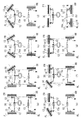
車両Cの走行モードの切り替え方法の一連の手順について、図6及び図7を用いて説明する。この説明に係る車両Cは、前輪FR、FLにインホイールモータMを備えていない従動輪、後輪RR、RLにインホイールモータMを備えた駆動輪を有しており、前輪FR、FL側に従動輪用ステアリング装置30が、後輪RR、RL側に駆動輪用ステアリング装置10がそれぞれ設けられている。従動輪用ステアリング装置30は、運転者のステアリング1の操作に基づいて駆動される一方で、駆動輪用ステアリング装置10は、アクチュエータ(図示せず)によって駆動される。
(2) About the switching method of the driving mode of a vehicle A series of procedures of the switching method of the driving mode of the vehicle C are demonstrated using FIG.6 and FIG.7. The vehicle C according to this description includes a driven wheel that does not include the in-wheel motor M on the front wheels FR and FL, and a drive wheel that includes the in-wheel motor M on the rear wheels RR and RL. A driven
(a)通常走行モードから横方向移動モードへの切り替え(図6)
通常走行モード(本図(a))から横方向移動モード(本図(h))への切り替えについて説明する。通常走行モードにおいては、駆動輪用ステアリング装置10及び従動輪用ステアリング装置30に設けられたロック機構16(図3及び図8参照)が、いずれも通常走行モードに対応するロック位置でロックされた状態となっている(本図(a))。
(A) Switching from the normal travel mode to the lateral movement mode (FIG. 6)
Switching from the normal travel mode (this figure (a)) to the lateral movement mode (this figure (h)) will be described. In the normal travel mode, the lock mechanisms 16 (see FIGS. 3 and 8) provided in the drive
まず、左前輪FLのロック機構16を解除した上で、ステアリング1を左向きに操作する。すると、転舵装置15のラックバー15aが右向きに移動して右前輪FRが左向きに転舵する。左前輪FLは、そのロック機構16が解除されていることから、左前輪FLのナックル12は、第一のキングピン軸13及び第二のキングピン軸14のいずれの軸周りにも自在に回動し得るようになっている。ところが、路面との間の摩擦によって転舵することができないため、左前輪FLに対してナックル12のみが、両キングピン軸13、14周りに回動する。このため、ナックル12の位置が、通常走行モードに対応するロック位置からずれた状態となる(本図(b))。
First, after releasing the
次に、右前輪FRが左向きにある程度の舵角だけ転舵したら、この右前輪FRのロック機構16を解除した上で、ステアリング1を右向きに操作する。このとき、左右前輪FL、FRのいずれのロック機構16も解除されているため、左右前輪FL、FRのいずれも転舵することなく、それらのナックル12、12のみが両キングピン軸13、14周りに回動する。そして、左前輪FLのナックル12が、通常走行モードに対応する位置となったときに、この左前輪FLのロック機構16をロック状態とする。引き続き、ステアリング1を右向きに操作すると、左前輪FLは右向きに転舵する一方で、右前輪FRは転舵することなくそのナックル12のみが両キングピン軸13、14周りに回動し、左右前輪FL、FRが、ハの字形を形成する(本図(c))。
Next, when the right front wheel FR is steered to a left by a certain steering angle, the
さらに、左右前輪FL、FRのロック機構16を解除した上で、ステアリング1の位置(右向きに操作した状態となっている)を固定したまま、左右後輪RL、RRにそれぞれ設けたインホイールモータMを後退方向に駆動する。このとき、ステアリング1の位置が固定されていることから、左右前輪FL、FRのナックル12は第一のキングピン軸13周りに回動することができず、左右前輪FL、FRは第二のキングピン軸14周りに左右方向(左右前輪FL、FRの転舵角度が大きくなる方向)に回動する。
Further, the in-wheel motors provided on the left and right rear wheels RL and RR, respectively, with the position of the steering wheel 1 (operated to the right) being fixed after releasing the
そして、右前輪FRのナックル12が、横方向移動モードに対応する位置となったときに、この右前輪FRのロック機構16のみをロック状態とする(本図(d))。この右前輪FRのロック機構16をロックさせるのと同時に、インホイールモータMの駆動を停止する。
When the
さらに、ステアリング1を左向きに操作すると、ロック状態を解除したままの左前輪FLのナックル12が、両キングピン軸13、14周りに回動する一方で、ロック状態とした右前輪FRは左向きに転舵する。そして、右前輪FRの転舵角が車両の前後方向に対して90度となったとき(ステアリング1が中立状態となったとき)に右前輪FRのロック状態16を解除する(本図(e))。この状態からさらにステアリング1を左向きに操作し、左前輪FLのナックル12が、横方向移動モードに対応する位置になったときに、この左前輪FLのロック機構16をロック状態とする。このとき、右前輪FRは、転舵することなくそのナックル12のみが両キングピン軸13、14周りに回動する(本図(f))。
Further, when the
さらに、ステアリング1を右向きに操作すると、左前輪FLが右向きに転舵し、左前輪FLの転舵角が車両の前後方向に対して90度となったとき(ステアリング1が中立状態となったとき)に、右前輪FRのロック機構16をロック状態とする。これにより、左右前輪FL、FRが、横方向移動モードに対応する向きに転舵される(本図(g))。
Further, when the
最後に、駆動用ステアリング装置10の中立状態を保ったまま、左右後輪RL、RRのロック機構16を解除し、インホイールモータMを後退方向に駆動する。このとき、左右前輪FL、FRは、横向きに転舵されているため車両は後退することができず、しかも、左右後輪RL、RRのナックル12は、第一のキングピン軸13周りに回動することができないため、インホイールモータMの駆動に伴って、左右後輪RL、RRは第二のキングピン軸14周りに左右方向(左右後輪RL、RRの転舵角度が大きくなる方向)に転舵する。左右後輪RL、RRの転舵角が、車両の前後方向に対して90度となったときに、左右後輪RL、RRのロック機構16をロック状態とするとともに、インホイールモータMの駆動を停止する。これにより、左右前後の全ての車輪FL、FR、RL、RRが横方向に90度転舵された、横方向移動モードとすることができる(本図(h))。
Finally, while maintaining the neutral state of the driving
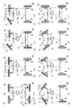
(b)横方向移動モードから通常走行モードへの切り替え(図7)
横方向移動モード(本図(a))から通常走行モード(本図(h))への切り替えについて説明する。横方向移動モードにおいては、駆動輪用ステアリング装置10及び従動輪用ステアリング装置30に設けられたロック機構16(図3及び図8参照)が、いずれも横方向移動モードに対応するロック位置でロックされた状態となっている(本図(a))。
(B) Switching from the lateral movement mode to the normal travel mode (FIG. 7)
Switching from the lateral movement mode (this figure (a)) to the normal travel mode (this figure (h)) will be described. In the lateral movement mode, the lock mechanism 16 (see FIGS. 3 and 8) provided in the driving
まず、駆動用ステアリング装置10の中立状態を保ったまま、左右後輪RL、RRのロック機構16を解除し、インホイールモータMを前進方向に駆動する。このとき、左右前輪FL、FRは、横向きに転舵されているため車両は前進することができず、しかも、左右後輪RL、RRのナックル12は、第一のキングピン軸13周りに回動することができないため、インホイールモータMの駆動に伴って、左右後輪RL、RRは第二のキングピン軸14周りに前後方向(左右後輪RL、RRが互いに平行になる方向)に転舵する。左右後輪RL、RRが車両の前後方向に対して0度となったときに、左右後輪RL、RRのロック機構16をロック状態とするとともに、インホイールモータMの駆動を停止する(本図(b))。
First, while maintaining the neutral state of the
次に、右前輪FRのロック機構16を解除した上で、ステアリング1を左向きに操作すると、ロック状態としたままの左前輪FLは左向きに転舵する。右前輪FRは、そのロック機構16が解除されていることから、右前輪FRのナックル12は、第一のキングピン軸13及び第二のキングピン軸14のいずれの軸周りにも自在に回動し得るようになっている。ところが、路面との間の摩擦によって転舵することができないため、右前輪FRに対してナックル12のみが両キングピン軸13、14周りに回動する。このため、ナックル12の位置が、横方向移動モードに対応するロック位置からずれた状態となる(本図(c))。
Next, when the
左前輪FLが左向きにある程度転舵したら、この左前輪FLのロック機構16を解除した上で、ステアリング1を右向きに操作する。このとき、左右前輪FL、FRのいずれのロック機構16も解除されているため、左右前輪FL、FRのいずれも転舵することなく、それらのナックル12のみが両キングピン軸13、14周りに回動する。そして、右前輪FRのナックル12が、横方向移動モードに対応する位置となったとき(ステアリング1が中立状態となったとき)に、この右前輪FRのロック機構16をロック状態とする(本図(d))。
When the left front wheel FL is steered to the left to some extent, the
引き続き、ステアリング1を右向きに操作すると、左前輪FLは転舵することなくそのナックル12のみが両キングピン軸13、14周りに回動する一方で、右前輪FRは右向きに転舵する(本図(e))。この状態で、右前輪FRのロック機構16を解除し、ステアリング1の位置(右向きに転舵した状態となっている)を固定したまま、左右後輪RL、RRにそれぞれ設けたインホイールモータMを前進方向に駆動する。このとき、ステアリング1の位置が固定されていることから、左右前輪FL、FRのナックル12は第一のキングピン軸13周りに回動することができず、左右前輪FL、FRは第二のキングピン軸14周りに前後方向(左右前輪FL、FRが平行に近付く方向)に回動する。
Subsequently, when the
そして、左前輪FLのナックル12が、通常走行モードに対応する位置となったときに、この左前輪FLのロック機構16のみをロックした状態とする(本図(f))。この左前輪FLのロック機構16をロックさせるのと同時に、インホイールモータMの駆動を停止する。
When the
さらに、ステアリング1を左向きに操作すると、ロック状態とした左前輪FLは左向きに転舵する一方で、ロック状態を解除したままの右前輪FRのナックル12が、両キングピン軸13、14周りに回動する。そして、右前輪FRのナックル12が、通常走行モードに対応する位置になったときに、左右前輪FL、FRのロック機構16をロック状態とすることにより、左右前後の全ての車輪FL、FR、RL、RRを通常走行モードとすることができる(本図(g))。このロック状態で、ステアリング1を右向きに操作して中立状態とすると、左右前輪FL、FRを直進状態とすることができる(本図(h))。
Further, when the
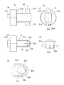
車両C(図4参照)に採用される第二のキングピン軸14周りのロック機構16について、図8から図12を用いて説明する。このロック機構16は、軸支部材31、ナックル12、及びロック装置32を主要な構成要素としている。図8はロック機構16の要部(ロック装置32の近傍)を、図9は軸支部材31を、図10はナックル12を、図11はロック装置32を、図12はロック装置16の作用をそれぞれ示している。
The
軸支部材31は、車輪wの回転軸方向に延設された本体部31aを有し、この本体部31aには、上下方向に延びる軸部31bが突設されている(図9(a)(b)参照)。この軸部31bは後述するナックル12に形成された貫通孔12dに挿し込まれ、第二のキングピン軸14周りに回転自在となっている。この軸部31bの下端外周面には、車両Cが備える各走行モードにおける車輪wの転舵角度に対応する位置に、断面が半円弧状のロック溝33(33a、33b、33c)が形成されている(図9(b)(c)参照)。この実施形態においては、ロック溝33aが通常走行モードに、ロック溝33bがその場回転モードに、ロック溝33cが横方向移動モードにそれぞれ対応している。
The
三種類の走行モードを備える車両Cの場合、三カ所にロック溝33a、33b、33cが形成されるが、このロック溝33a、33b、33cの数は、その車両Cが備える走行モードの種類に対応して適宜増減される。本体部31aの端部には、嵌合突起31cが形成されており(図9(a)(b)参照)、この嵌合突起31cがホイールに嵌め込まれることによって、軸支部材31が車輪wに固定される(図3参照)。
In the case of the vehicle C having three types of travel modes,
ナックル12は、側面視コの字形の本体部12aを有し、この本体部12aには、上下方向に、第一のキングピン軸13周りに回転自在な軸部12bが突設されている(図10(a)(c)参照)。軸部12bの先端に形成された球状の部分に、アッパーアーム11a及びロワアーム11b(図3参照)がそれぞれ接続される。本体部12aの中ほどには、延設部12cが延設されており、この延設部12cの先端に、タイロッド17(図3参照)が接続される。
The
ナックル12の本体部12aには、軸支部材31に突設した軸部31bを挿し込む一対の貫通孔12d、12dが形成されている。一対の貫通孔12d、12dのうち下側の貫通孔12dの内周面には、断面が半円弧状のロック溝12eが一カ所形成されている(図10(e)(f)参照)。貫通孔12dに挿し込まれた軸支部材31の軸部31bを第二のキングピン軸14周りに回転して、この軸部31bの外周面に形成されたロック溝33a、33b、33cのいずれかと、貫通孔12dの内周面に形成されたロック溝12e(図10(b)(e)参照)の位置を合わせると、一つの円形のロック穴が形成される。
A pair of through
ロック装置32は、有底筒状のハウジング34を有し、このハウジング34の内部に、ソレノイドコイル35と、ロックプランジャ36が設けられている。このロックプランジャ36の先端には、ロックピン36aが形成されている。ロックプランジャ36とハウジング34との間には、付勢部材(図示せず)が介在して設けられている。
The
ソレノイドコイル35の非作動時は、前記付勢部材の付勢力によって、ロックピン36aがハウジング34から突出し(図11(a)参照)、このロックピン36aが、軸部31bと貫通孔12dの内周面との間に形成された円形のロック穴に挿し込まれる(図8(a)参照)。ロック穴にロックピン36aが挿し込まれることによって、ナックル12が第二のキングピン軸14周りに回転できない状態(ロック状態)となる。
When the
その一方で、ソレノイドコイル35の作動時は、このソレノイドコイル35の磁力によってロックプランジャ36がハウジング34の内側に引き付けられて(図11(c)参照)、ロック穴からロックピン36aが退去する(図8(b)参照)。これにより、ナックル12が第二のキングピン軸14周りに回転自在の状態(ロック解除状態)となる。
On the other hand, when the
図12に示すように、通常走行モードにおいては、軸部31bに形成されたロック溝33aと、貫通孔12dの内周面に形成されたロック溝12eとによって形成されるロック穴に(本図(b)参照)、その場回転モードにおいては、軸部31bに形成されたロック溝33bと、貫通孔12dの内周面に形成されたロック溝12eとによって形成されるロック穴に(本図(d)参照)、横方向移動モードにおいては、軸部31bに形成されたロック溝33cと、貫通孔12dの内周面に形成されたロック溝12eとによって形成されるロック穴に(本図(f)参照)、ロックピン36a(図8(a)参照)がそれぞれ挿し込まれ、各走行モードに対応する車輪wの転舵角度においてナックル12がロックされる。なお、図12の各図においては、ロック装置32(ロックピン36a以外)の図示を省略している。
As shown in FIG. 12, in the normal travel mode, the lock hole formed by the
なお、図6及び図7に示した走行モードの切り替え手順は、あくまでも例示に過ぎない。この手順と同様の手順で、例えば、通常走行モードとその場回転モードとの間で、走行モードの切り替えを行うこともできる。また、通常走行モードと横方向移動モードとの間で走行モードの切り替えを行うときに、両モードの間で直接切り替えを行うのではなく、例えば、モード切り替えの途中で、その場回転モード等の他の走行モードを介在させてもよい。車輪wの転舵角度差が大きい走行モード(例えば、通常走行モードと横方向移動モード)の間に、両走行モードの中間の転舵角度の走行モード(例えば、その場回転モード)を介在させることにより、走行モードの切り替えを一層スムーズに行うことができるためである。 The travel mode switching procedures shown in FIGS. 6 and 7 are merely examples. In the same procedure as this procedure, for example, the driving mode can be switched between the normal driving mode and the spot rotation mode. In addition, when switching the driving mode between the normal driving mode and the lateral movement mode, instead of switching directly between the two modes, for example, in the middle of the mode switching, Other driving modes may be interposed. Between the driving modes (for example, the normal driving mode and the lateral movement mode) having a large difference in the turning angle of the wheels w, the driving mode (for example, the in-situ rotation mode) having an intermediate steering angle between the two driving modes is interposed. This is because the driving mode can be switched more smoothly.
また、図6及び図7に示した走行モードの切り替え手順においては、従動輪の走行モードの切り替えのアシストとして、駆動輪に設けたインホイールモータMの駆動力を利用したが、従動輪用ステアリング装置30で車輪wを左右に転舵しつつ、ロック機構16によるロック及びロック解除を適宜行うことにより、インホイールモータMの駆動力によるアシストを受けることなく、従動輪の走行モードの切り替えを行うことができる場合もある。また、駆動輪の走行モードの切り替えを従動輪の走行モードの切り替えと同様に、インホイールモータMの駆動力を用いることなく行うことができる場合もある。
In the travel mode switching procedure shown in FIGS. 6 and 7, the driving force of the in-wheel motor M provided on the driving wheel is used as an assist for switching the traveling mode of the driven wheel. The driving mode of the driven wheels is switched without receiving assistance from the driving force of the in-wheel motor M by appropriately performing locking and unlocking by the
(3)各走行モードについて
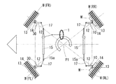
車両C(図4参照)の走行モードを図13から図16に示す平面図を用いて説明する。各図中に記載の白三角形は車両Cの前方を示し、白抜きの矢印は各走行モード(又は転舵状態)における車両Cの進行方向を表す。なお、これらの各図は、各走行モード時における車輪wの転舵方向に注目するために、駆動輪用ステアリング装置10と従動輪用ステアリング装置30との間の制御系及び駆動系の詳細については記載を省略している。また、ここで示す車両Cにおいては、左右後輪RL、RRのみにインホイールモータMが設けられているが、左右前輪FL、FRのみ又は全ての車輪FL、FR、RL、RRにインホイールモータMを設けた構成とすることもできる。
(3) About each driving mode The driving mode of the vehicle C (refer FIG. 4) is demonstrated using the top view shown to FIGS. The white triangle described in each figure indicates the front of the vehicle C, and the white arrow indicates the traveling direction of the vehicle C in each travel mode (or steered state). Each of these drawings shows details of the control system and the drive system between the drive
(a)通常走行モード(図13)
通常走行モードは、一般的な車両と同様に、通常の走行時において前輪FL、FRを左右同方向に転舵するモードである。通常走行モードにおいては、駆動輪用ステアリング装置10及び従動輪用ステアリング装置30のロック機構16(本図及び後で説明する図14から図16では記載を省略している。図1及び図3を参照)は、通常走行モードに対応する位置においてロックされている。このロックによって、ナックル12は第二のキングピン軸14周りに回動不能となる。この状態でステアリング1を操作すると、前輪FL、FRを左右に転舵することができる。例えば、図13に示すように前輪FL、FRを右に転舵した状態で、後輪RL、RRに設けたインホイールモータMを駆動すると、本図中に白抜きの矢印で示すように、車両Cを右折することができる。
(A) Normal driving mode (Fig. 13)
The normal travel mode is a mode in which the front wheels FL and FR are steered in the same direction in the left and right during normal travel, as in a general vehicle. In the normal travel mode, the
(b)その場回転モード(図14)
その場回転モードは、同一の位置で車両Cの向きを変更するモードである。その場回転モードは、図6で説明した横方向移動モードの場合と、各車輪w(FL、FR、RL、RR)の転舵角度が異なるが、通常の走行モードからその場回転モードへの切り替えは、同様の手順で行うことができる。その場回転モードにおいては、駆動輪用ステアリング装置10及び従動輪用ステアリング装置30のロック機構16は、その場回転モードに対応する位置においてロックされている。この状態で後輪RL、RRに設けたインホイールモータMのうち少なくとも一つを駆動すると、車両Cは回転中心P1を中心として回転し、この車両Cの向きを変更することができる。なお、その場回転モードにおいてもステアリング1を操作することができ、このステアリング操作によって、車両Cの回転中心P1の位置をずらすことも可能である。
(B) In-situ rotation mode (FIG. 14)
The spot rotation mode is a mode in which the direction of the vehicle C is changed at the same position. The in-situ rotation mode differs from the case of the lateral movement mode described in FIG. 6 in that the steering angle of each wheel w (FL, FR, RL, RR) is different, but from the normal traveling mode to the in-situ rotation mode. Switching can be performed in the same procedure. In the spot rotation mode, the
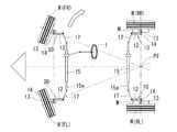
(c)横方向移動モード(図15)
横方向移動モードは、車両Cが前方を向いた状態のまま、この車両1の直進方向に対して90度直交する方向に移動させるモードである。図6において説明したように、横方向移動モードにおいては、駆動輪用ステアリング装置10及び従動輪用ステアリング装置30のロック機構16は、横方向移動モードに対応する位置においてロックされている。この状態で後輪RL、RRに設けたインホイールモータMのうち少なくとも一つを駆動すると、通常の走行方向に対して車両Cを真横に移動することができる。なお、この横方向移動モードにおいてもステアリング1を操作することができ、このステアリング操作によって、車両Cの移動方向を真横から少し前後いずれかに偏った方向に調節することも可能である。
(C) Lateral movement mode (FIG. 15)
The lateral movement mode is a mode in which the vehicle C is moved in a direction orthogonal to the straight traveling direction of the
(d)小回りモード(図16)
小回りモードは、ほぼ同一の位置で車両Cの向きを変更するモードである。小回りモードは、図6で説明した横方向移動モードの場合と前輪FL、FRの転舵角度と、後輪RL、RRを転舵しない点が異なるが、通常の走行モードから小回りモードへの切り替えは、ほぼ同様の手順で行うことができる。小回りモードにおいては、駆動輪用ステアリング装置10及び従動輪用ステアリング装置30のロック機構16は、小回りモードに対応する位置においてロックされている。この状態で前輪FL、FRに設けたインホイールモータMのうち少なくとも一つを駆動すると、車両Cは回転中心P2を中心として回転し、この車両Cの向きを変更することができる。なお、この小回りモードにおいてもステアリング1を操作することができ、このステアリング操作によって、車両Cの回転中心P2の位置をずらすことも可能である。
(D) Small turning mode (FIG. 16)
The small turn mode is a mode in which the direction of the vehicle C is changed at substantially the same position. The small turning mode is different from the case of the lateral movement mode described in FIG. 6 in that the turning angle of the front wheels FL and FR and the rear wheels RL and RR are not steered. Can be performed in substantially the same procedure. In the small turning mode, the
上記実施形態に係るステアリング装置10、30、及び車両Cの走行モードの切り替え方法はあくまでも一例であって、簡便な装置構成で、通常走行モードから特殊走行モードへの切り替えを行う、という本願発明の課題を解決し得る限りにおいて、各ステアリング装置10、30の構成の一部を変更したり、走行モードの切り替え方法のステップに他のステップを追加したりすることも許容される。
The
1 ステアリング
10 (駆動輪用)ステアリング装置
11 懸架装置
11a アッパーアーム
11b ロワアーム
12 ナックル
12a 本体部
12b 軸部
12c 延設部
12d 貫通孔
12e ロック溝
13 第一のキングピン軸
14 第二のキングピン軸
15 転舵装置
16 ロック機構
17 タイロッド
18 ロック部本体
19a、19b、19c 係合凹部
20 ロックバー
21 ソレノイド動作部
30 (従動輪用)ステアリング装置
31 軸支部材
31a 本体部
31b 軸部
31c 嵌合突起
32 ロック装置
33a、33b、33c ロック溝
34 ハウジング
35 ソレノイドコイル
36 ロックプランジャ
36a ロックピン
r1 (第一のキングピン軸の)スクラブ半径
r2 (第二のキングピン軸の)スクラブ半径
C 車両
M 駆動源(インホイールモータ)
w 車輪
FR 右前輪
FL 左前輪
RR 右後輪
RL 左後輪
DESCRIPTION OF
w Wheel FR Right front wheel FL Left front wheel RR Right rear wheel RL Left rear wheel
Claims (7)
前記懸架装置(11)に対し、前記ナックル(12)を転舵方向に回動する第一のキングピン軸(13)と、
前記ナックル(12)に対し、車輪(w)を車両(C)の各走行モードに対応する角度に回動する第二のキングピン軸(14)と、
前記第一のキングピン軸(13)周りに前記車輪(w)を左右同方向に転舵可能な転舵装置(15)と、
前記第二のキングピン軸(14)周りの前記車輪(w)の回動を、前記各走行モードに対応する位置でロック可能なロック機構(16)と、
を備えたステアリング装置。 A knuckle (12) provided on the chassis via a suspension (11);
A first kingpin shaft (13) for rotating the knuckle (12) in a steering direction with respect to the suspension device (11);
A second kingpin shaft (14) for rotating the wheel (w) to an angle corresponding to each travel mode of the vehicle (C) with respect to the knuckle (12);
A turning device (15) capable of turning the wheel (w) in the same direction left and right around the first kingpin shaft (13);
A lock mechanism (16) capable of locking the rotation of the wheel (w) around the second kingpin shaft (14) at a position corresponding to each of the travel modes;
Steering device with
前記ロック機構(16)をロック状態とした上で、前記ナックル(12)に連結された左右の前記車輪(w)を左右同方向に転舵可能な転舵装置(15)を駆動し、前記ナックル(12)を前記第一のキングピン軸(13)周りに回動して車輪(w)を転舵する車輪転舵ステップと、
前記ロック機構(16)をロック解除状態とした上で、前記ナックル(12)に連結された前記転舵装置(15)を駆動し、前記車輪(w)と路面との間の摩擦によってこの車輪(w)の転舵を防止しつつ、前記ナックル(12)を前記第一のキングピン軸(13)周り及び前記第二のキングピン軸(14)周りに回動して走行モードを切り替える、第一走行モード切替ステップと、
を交互に又はいずれか一方を行うことにより車両(C)の走行モードを切り替える車両の走行モードの切り替え方法。 A first kingpin shaft (13) for rotating the knuckle (12) in a turning direction relative to the suspension device (11) on a knuckle (12) provided on the chassis via the suspension device (11); A second kingpin shaft (14) is provided for rotating the wheel (w) in a direction corresponding to the travel mode of the vehicle (C) with respect to the knuckle (12), and the second kingpin shaft (14). A lock mechanism (16) capable of locking the rotation of the surrounding wheel (w) at a position corresponding to each travel mode that the vehicle (C) can take;
Driving the steering device (15) capable of steering the left and right wheels (w) connected to the knuckle (12) in the same direction in the left and right direction, with the locking mechanism (16) in a locked state, A wheel turning step of turning the knuckle (12) around the first kingpin axis (13) to steer the wheel (w);
After the lock mechanism (16) is unlocked, the steering device (15) connected to the knuckle (12) is driven, and this wheel is caused by friction between the wheel (w) and the road surface. The first knuckle (12) is rotated around the first kingpin shaft (13) and the second kingpin shaft (14) while switching the running mode while preventing the steering of (w). A driving mode switching step;
A method for switching the travel mode of the vehicle that switches the travel mode of the vehicle (C) by alternately or any of the above.
Priority Applications (1)
| Application Number | Priority Date | Filing Date | Title |
|---|---|---|---|
| PCT/JP2015/075406 WO2016039312A1 (en) | 2014-09-11 | 2015-09-08 | Steering device and vehicle running mode switching method |
Applications Claiming Priority (2)
| Application Number | Priority Date | Filing Date | Title |
|---|---|---|---|
| JP2015122851 | 2015-06-18 | ||
| JP2015122851 | 2015-06-18 |
Publications (1)
| Publication Number | Publication Date |
|---|---|
| JP2017007633A true JP2017007633A (en) | 2017-01-12 |
Family
ID=57761192
Family Applications (1)
| Application Number | Title | Priority Date | Filing Date |
|---|---|---|---|
| JP2015145034A Pending JP2017007633A (en) | 2014-09-11 | 2015-07-22 | Steering device and switching method of traveling mode of vehicle |
Country Status (1)
| Country | Link |
|---|---|
| JP (1) | JP2017007633A (en) |
Cited By (3)
| Publication number | Priority date | Publication date | Assignee | Title |
|---|---|---|---|---|
| JP2019214369A (en) * | 2019-07-31 | 2019-12-19 | Ntn株式会社 | Hub bearing with steering shaft and hub unit with steering function |
| CN115289543A (en) * | 2022-07-27 | 2022-11-04 | 青岛海尔空调器有限总公司 | Household electrical appliance |
| US11565548B2 (en) | 2017-11-28 | 2023-01-31 | Ntn Corporation | Hub unit having steering function, and vehicle provided with said hub unit |
-
2015
- 2015-07-22 JP JP2015145034A patent/JP2017007633A/en active Pending
Cited By (3)
| Publication number | Priority date | Publication date | Assignee | Title |
|---|---|---|---|---|
| US11565548B2 (en) | 2017-11-28 | 2023-01-31 | Ntn Corporation | Hub unit having steering function, and vehicle provided with said hub unit |
| JP2019214369A (en) * | 2019-07-31 | 2019-12-19 | Ntn株式会社 | Hub bearing with steering shaft and hub unit with steering function |
| CN115289543A (en) * | 2022-07-27 | 2022-11-04 | 青岛海尔空调器有限总公司 | Household electrical appliance |
Similar Documents
| Publication | Publication Date | Title |
|---|---|---|
| JP6351944B2 (en) | Steering device | |
| EP3028927B1 (en) | Steering device and vehicle with same | |
| JP5447683B2 (en) | Car body tilting device | |
| US9834249B2 (en) | Vehicle with steering devices for front and rear wheels | |
| US9758190B2 (en) | Vehicle | |
| WO2014171389A1 (en) | Steering device, vehicle using same steering device, and vehicle equipped with four-wheel steering mechanism | |
| JP2012121391A (en) | Steering device | |
| JP2017007633A (en) | Steering device and switching method of traveling mode of vehicle | |
| JP6246010B2 (en) | Switching method of vehicle and running mode | |
| JP2016055804A (en) | Steering device and method for changing driving modes of vehicle | |
| WO2016039312A1 (en) | Steering device and vehicle running mode switching method | |
| WO2015050190A1 (en) | Steering device | |
| WO2015076209A1 (en) | Drive/turn module, and vehicle provided with drive/turn module | |
| WO2016121677A1 (en) | Steering device and vehicle equipped with same | |
| WO2016117585A1 (en) | Steering apparatus | |
| JP6437189B2 (en) | Steering device and steering device system | |
| WO2015146803A1 (en) | Driving mode switch control method and vehicle | |
| JP2014210484A (en) | Vehicle with four-wheel steering mechanism | |
| JP2016088410A (en) | Vehicular steering device | |
| JP2016132316A (en) | Steering device and vehicle | |
| JP2006160166A (en) | Wheel steering mechanism | |
| JP2017109546A (en) | Steering device and vehicle |