JP2017007577A - Cab stopper device of vehicle with frame - Google Patents
Cab stopper device of vehicle with frame Download PDFInfo
- Publication number
- JP2017007577A JP2017007577A JP2015126669A JP2015126669A JP2017007577A JP 2017007577 A JP2017007577 A JP 2017007577A JP 2015126669 A JP2015126669 A JP 2015126669A JP 2015126669 A JP2015126669 A JP 2015126669A JP 2017007577 A JP2017007577 A JP 2017007577A
- Authority
- JP
- Japan
- Prior art keywords
- vehicle
- movable
- frame
- deployment member
- deployment
- Prior art date
- Legal status (The legal status is an assumption and is not a legal conclusion. Google has not performed a legal analysis and makes no representation as to the accuracy of the status listed.)
- Pending
Links
Images


Classifications
-
- B—PERFORMING OPERATIONS; TRANSPORTING
- B60—VEHICLES IN GENERAL
- B60R—VEHICLES, VEHICLE FITTINGS, OR VEHICLE PARTS, NOT OTHERWISE PROVIDED FOR
- B60R21/00—Arrangements or fittings on vehicles for protecting or preventing injuries to occupants or pedestrians in case of accidents or other traffic risks
- B60R21/02—Occupant safety arrangements or fittings, e.g. crash pads
-
- B—PERFORMING OPERATIONS; TRANSPORTING
- B62—LAND VEHICLES FOR TRAVELLING OTHERWISE THAN ON RAILS
- B62D—MOTOR VEHICLES; TRAILERS
- B62D21/00—Understructures, i.e. chassis frame on which a vehicle body may be mounted
- B62D21/02—Understructures, i.e. chassis frame on which a vehicle body may be mounted comprising longitudinally or transversely arranged frame members
-
- B—PERFORMING OPERATIONS; TRANSPORTING
- B62—LAND VEHICLES FOR TRAVELLING OTHERWISE THAN ON RAILS
- B62D—MOTOR VEHICLES; TRAILERS
- B62D27/00—Connections between superstructure or understructure sub-units
- B62D27/04—Connections between superstructure or understructure sub-units resilient
Abstract
Description
本発明は、フレーム付車両のキャブストッパ装置に関する。 The present invention relates to a cab stopper device for a vehicle with a frame.
特許文献1には、フレームに支持ブラケットを固定し、支持ブラケットにストッパ装置を装備し、ストッパ装置に対向する突出部を車体の下面に設けたフレーム付車両の車体構造が記載されている。ストッパ装置は第1及び第2のストッパ部材を備え、第1のストッパ部材は突出部に対して間隔を有する位置に配設される。車体は、フレームに対してゴム部材等の弾性部材を介して搭載され、通常の走行状態にあっても、車体はフレームに対して水平方向にある程度の距離内で移動する。間隔は、通常の車体とフレームとの間の相対移動よりも大きな寸法に設定される。車両が前面衝突を起こすと、フレームに大きな負の加速度が作用し、車体は慣性力の作用により前方へ移動し、突起部が第1のストッパ部材に衝突する。第1のストッパ部材が車体の慣性力により変形して第2のストッパ部材に当接すると、第2のストッパ部材によって車体の前方への移動が規制される。
特許文献1の構造では、フレームに固定される第1のストッパ部材(第1ストッパ部)と車体(ボディ)に固定される突出部(第2ストッパ部)との間に間隔(可動空間)が設けられているので、前面衝突の際、第2ストッパ部が可動空間を移動して第1ストッパ部に衝突するまでの間はボディがフレームに対して前方へ移動する。ボディが前方へ移動すると、キャブの前部が衝突によって変形し、乗員の生存空間を狭めてしまう可能性がある。
In the structure of
なお、このような不都合は、第1ストッパ部と第2ストッパ部との間に可動空間を設けずに、両者を通常時から近接又は接触させることによって抑制することが可能である。しかし、可動空間を無くしてしまうと、通常時の車両の走行中に第1ストッパ部と第2ストッパ部とが干渉し、ボディの弾性支持が損なわれてしまう。 Such inconvenience can be suppressed by providing a movable space between the first stopper portion and the second stopper portion without bringing a movable space between the first stopper portion and the second stopper portion. However, if the movable space is eliminated, the first stopper portion and the second stopper portion interfere with each other during traveling of the vehicle at normal times, and the elastic support of the body is impaired.
そこで、本発明は、車両の通常走行時のボディの弾性支持を損なうことなく、車両の前面衝突時の乗員の生存空間を十分に確保することが可能なフレーム付車両のストッパ装置の提供を目的とする。 Accordingly, the present invention has an object to provide a stopper device for a vehicle with a frame that can sufficiently secure a living space for an occupant during a frontal collision of the vehicle without impairing the elastic support of the body during normal traveling of the vehicle. And
上記目的を達成すべく、本発明の第1の態様は、フレームによってボディが弾性支持されるフレーム付車両のキャブストッパ装置であって、第1ストッパ部と、第2ストッパ部と、可動部材と、衝突検知手段と、作動手段と、を備える。 In order to achieve the above object, a first aspect of the present invention is a cab stopper device for a vehicle with a frame whose body is elastically supported by a frame, the first stopper portion, the second stopper portion, a movable member, A collision detection means and an actuation means.
第1ストッパ部は、フレームに対して固定される。第2ストッパ部は、第1ストッパ部の後方に対向配置され、第1ストッパ部との間に所定の可動空間を区画し、ボディに対して固定される。可動部材は、フレーム又はボディに支持され、可動空間外の格納位置から可動空間内の作動位置へ突出可能である。衝突検知手段は、車両の前面衝突を検知する。作動手段は、衝突検知手段が車両の前面衝突を検知したとき、可動部材を格納位置から作動位置へ突出させる。 The first stopper portion is fixed to the frame. The second stopper portion is disposed opposite to the rear of the first stopper portion, divides a predetermined movable space with the first stopper portion, and is fixed to the body. The movable member is supported by the frame or the body, and can project from a storage position outside the movable space to an operating position within the movable space. The collision detection means detects a frontal collision of the vehicle. The operating means causes the movable member to protrude from the retracted position to the operating position when the collision detecting means detects a frontal collision of the vehicle.
可動空間は、可動部材が格納位置に保持された格納状態で、第1ストッパ部に対する第2ストッパ部の前方への移動を許容する。作動位置へ突出した作動状態の可動部材は、第1ストッパ部に対する第2ストッパ部の前方への移動を規制する。 The movable space allows the second stopper portion to move forward relative to the first stopper portion in a retracted state in which the movable member is held at the retracted position. The movable member in the activated state protruding to the activated position restricts the forward movement of the second stopper portion relative to the first stopper portion.
上記構成では、衝突検知手段が前面衝突を検知しない車両の通常走行時では、可動部材が格納位置に保持されて可動空間から外れているので、第1ストッパ部に対する第2ストッパ部の前方への移動が可動空間によって許容される。このため、弾性支持されたボディがフレームに対して前方へ移動した場合であっても、第1ストッパ部と第2ストッパ部とが干渉せず、フレームによるボディの弾性支持が損なわれることがない。 In the above configuration, when the vehicle does not detect a frontal collision, the movable member is held at the retracted position and deviated from the movable space, so that the second stopper portion is moved forward of the second stopper portion with respect to the first stopper portion. Movement is allowed by the movable space. Therefore, even when the elastically supported body moves forward relative to the frame, the first stopper portion and the second stopper portion do not interfere with each other, and the elastic support of the body by the frame is not impaired. .
車両が前面衝突し、衝突検知手段がこれを検知すると、作動手段は可動部材を格納位置から作動位置へ突出させる。作動位置の可動部材は、可動空間を埋めるように可動空間内に突出し、第1ストッパ部に対する第2ストッパ部の前方への移動を規制するので、フレームに対するボディの前方への移動は可動部材によって迅速に規制される。このため、衝突によるキャブの前部の変形を抑制することができ、乗員の生存空間を十分に確保することができる。 When the vehicle collides with the front and the collision detection means detects this, the operating means causes the movable member to protrude from the retracted position to the operating position. The movable member at the operating position protrudes into the movable space so as to fill the movable space, and restricts the forward movement of the second stopper portion relative to the first stopper portion. Therefore, the forward movement of the body relative to the frame is performed by the movable member. Be regulated quickly. For this reason, the deformation | transformation of the front part of the cab by a collision can be suppressed, and a passenger | crew's survival space can fully be ensured.
また、前面衝突時のフレームに対するボディの前方への移動が可動部材によって迅速に規制され、係る規制によってボディの減速度が上昇するので、ボディの減速度の上昇に応じてシートベルトによる乗員の拘束やエアバッグの展開が開始される車両の場合、シートベルトによる乗員の拘束やエアバックの展開の開始時を早めることができる。 In addition, the forward movement of the body with respect to the frame at the time of a frontal collision is quickly regulated by the movable member, and the deceleration of the body is increased by such regulation, so that the restraint of the occupant by the seat belt according to the increase in the deceleration of the body Further, in the case of a vehicle in which the deployment of the airbag is started, it is possible to speed up the start of the restraint of the occupant by the seat belt and the deployment of the airbag.
本発明の第2の態様は、第1の態様のキャブストッパ装置であって、可動部材は、第1展開部材と第2展開部材とを有する。第1展開部材は、第1回転軸を中心としてフレーム又はボディに回転自在に支持される。第2展開部材は、第2回転軸を中心として第1展開部材に回転自在に連結される。格納状態では、第1展開部材と第2展開部材とが可動空間の近傍で直線状に重なる。作動状態では、第1展開部材が第1回転軸を中心として格納位置から傾動するとともに、第2展開部材が第2回転軸を中心として第1展開部材に対して傾動して、第1展開部材と第2展開部材とが可動空間内でX状に交叉して展開する。作動手段は、付勢手段とロック手段とロック解除手段とを有する。付勢手段は、格納位置の第1展開部材及び第2展開部材を作動位置へ付勢する。ロック手段は、第1展開部材及び第2展開部材を付勢手段の付勢力に抗して格納位置に保持する。ロック解除手段は、衝突検知手段が車両の前面衝突を検知したとき、ロック手段による格納状態の保持を解除する。 The 2nd mode of the present invention is the cab stopper device of the 1st mode, and a movable member has the 1st deployment member and the 2nd deployment member. The first deployment member is rotatably supported by the frame or the body around the first rotation axis. The second deployment member is rotatably coupled to the first deployment member about the second rotation axis. In the retracted state, the first deployment member and the second deployment member overlap linearly in the vicinity of the movable space. In the operating state, the first deployment member tilts from the retracted position about the first rotation axis, and the second deployment member tilts relative to the first deployment member about the second rotation axis. And the second expansion member expand in an X shape within the movable space. The actuating means has an urging means, a lock means, and a lock release means. The biasing means biases the first deployment member and the second deployment member at the storage position to the operating position. The locking means holds the first deployment member and the second deployment member in the retracted position against the urging force of the urging means. The lock release means releases the hold of the stored state by the lock means when the collision detection means detects a frontal collision of the vehicle.
上記構成では、格納状態では第1展開部材と第2展開部材とが直線状に重なるので、格納状態の第1展開部材及び第2展開部材を狭いスペースに配置することができ、省スペース化に寄与する。 In the above configuration, since the first deployment member and the second deployment member overlap in a straight line in the retracted state, the first deploying member and the second deployable member in the retracted state can be arranged in a narrow space, thereby saving space. Contribute.
また、衝突検知手段が車両の前面衝突を検知すると、ロック手段による格納状態の保持をロック解除手段が解除する。ロック手段による格納状態の保持が解除されると、付勢手段の付勢力によって、第1展開部材が第1回転軸を中心として格納位置から傾動するとともに、第2展開部材が第2回転軸を中心として第1展開部材に対して傾動して、第1展開部材と第2展開部材とがX状に展開する。付勢手段の付勢力によって第1展開部材と第2展開部材とが展開するので、駆動源を別途設けることなく、簡易な構造によって可動部材を瞬時に展開させることができる。 Further, when the collision detection means detects a frontal collision of the vehicle, the lock release means releases the stored state held by the lock means. When holding of the stored state by the locking means is released, the first deploying member tilts from the retracted position about the first rotating shaft by the biasing force of the biasing means, and the second deploying member moves the second rotating shaft. By tilting with respect to the first deployment member as a center, the first deployment member and the second deployment member are deployed in an X shape. Since the first deployment member and the second deployment member are deployed by the urging force of the urging means, the movable member can be deployed instantaneously with a simple structure without providing a separate drive source.
本発明のフレーム付車両のキャブストッパ装置によれば、車両の通常走行時のボディの弾性支持を損なうことなく、車両の前面衝突時の乗員の生存空間を十分に確保することができる。 According to the cab stopper device for a vehicle with a frame of the present invention, it is possible to sufficiently ensure the occupant's living space at the time of a frontal collision of the vehicle without impairing the elastic support of the body during normal traveling of the vehicle.
以下、本発明の第1実施形態に係るフレーム付車両(以下、単に車両と称する)1のキャブストッパ装置について、図1〜図6を参照して説明する。なお、以下の説明において、左右方向は、車両1の前方を向いた状態での左右方向を意味する。また、図中のFRは車両前方を、図中UPは車両上方を、図中INは車幅方向内側をそれぞれ示している。
Hereinafter, a cab stopper device of a vehicle with a frame (hereinafter simply referred to as a vehicle) 1 according to a first embodiment of the present invention will be described with reference to FIGS. In the following description, the left-right direction means the left-right direction with the
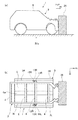
図1に示すように、車両1のフレーム2は、左右1対のサイドメンバ3L,3Rと複数のクロスメンバ4とを有するはしご形フレーム(ラダーフレーム)である。左右のサイドメンバ3L,3Rは、車幅方向の両側で前後方向に延びる。複数のクロスメンバ4は前後方向に相互に離間して車幅方向に延び、左右のサイドメンバ3L,3Rを連結する。車両1のボディ5は、フロアパネル6と左右1対のサイドシル7L,7Rを有する。フロアパネル6は、フレーム2の上方に配置されてキャブ8の底面を形成し、フロアパネル6の車幅方向の中央には、円弧状に上方へ膨出するトンネル部6aが折曲形成されている。左右のサイドシル7L,7Rは、フロアパネル6の車幅方向両側に固定され、左右のサイドメンバ3L,3Rの車幅方向外側で前後方向に延びる。左右のサイドメンバ3L,3Rの前端は、フロアパネル6及び左右のサイドシル7L,7Rの前端よりも前方へ延びる。左右のサイドシル7L,7Rは、ラバー等のマウント機構9(9L,9R)を介してフレーム2に弾性支持され、フロアパネル6には、乗員が着座する座席10が支持される。
As shown in FIG. 1, the
左右のサイドメンバ3L,3Rには、左右の第1ストッパ部11L,11Rがそれぞれ固定され、左右のサイドシル7L,7Rには、左右の第2ストッパ部12L,12Rがそれぞれ固定される。左右の第1ストッパ部11L,11Rは、左右のサイドメンバ3L,3Rから車幅方向外側に突出する。左右の第2ストッパ部12L,12Rは、左右の第1ストッパ部11L,11Rの後方で左右のサイドシル7L,7Rから車幅方向内側に突出して左右の第1ストッパ部11L,11Rの後面と対向し、第1ストッパ部11L,11Rとの間に所定の可動空間40を区画する。
The left and right
左右のサイドメンバ3L,3Rには、左右の可動部材13L,13Rがそれぞれ支持される。左右の可動部材13L,13Rは、可動空間40外の格納位置(図5(a)参照)から可動空間40内の作動位置(図5(b)参照)へ突出可能である。可動部材13L,13Rが格納位置に保持された格納状態で、可動空間40は、第1ストッパ部11L,11Rに対する第2ストッパ部12L,12Rの前方への移動を許容する。また、作動位置へ突出した作動状態の可動部材13L,13Rは、可動空間40を埋めるように第1ストッパ部11L,11Rと第2ストッパ部12L、12Rとの間に介在し、第2ストッパ部12L,12Rの前方への移動開始直後に第1ストッパ部11L,11Rと第2ストッパ部12L,12Rとに挟まれて、第1ストッパ部11L,11Rに対する第2ストッパ部12L,12Rの前方への移動を規制する。なお、左右の可動部材13L,13Rを、サイドメンバ3L,3Rではなく、ボディ5によって支持してもよい。
Left and right
次に、第1ストッパ部11L,11R及び第2ストッパ部12L,12Rとともに本実施形態のキャブストッパ装置を構成する上記左右の可動部材13L、13Rと、加速度センサ17と、ECU(Electric Control Unit)18と、左右のアクチュエータ19(右側のみ図示)とについて詳細に説明する。なお、可動部材13L,13R及びアクチュエータ19は左右で略同一に構成され、加速度センサ17及びECU18は左右で共用されるため、以下ではその一方(右側)について主に説明し、他方(左側)の説明を適宜省略する。
Next, the left and right
図2及び図3に示すように、可動部材13Rは、第1展開部材41と第2展開部材42とから構成される。第1展開部材41と第2展開部材42とは、相互に重ねられ組み合わされた状態で矩形板状となり(図2(a)参照)、両展開部材41,42の中央部同士を貫通して連結する回転軸(第2回転軸)16を中心として相対回転してX状に展開可能であり、且つ相対回転角度が所定の限界角度に達した際に両展開部材41,42同士が当接して展開方向への回転を規制する形状(図3(b)参照)に形成される。
As shown in FIGS. 2 and 3, the movable member 13 </ b> R includes a
可動部材13Rは、第2回転軸16が前後方向に沿って延びる姿勢で、第1ストッパ11Rと第2ストッパ12Rとの間でサイドメンバ3Rの車幅方向外側に配置される。第1展開部材41の一端部(車幅方向外端部)は、蝶番43を介してサイドメンバ3Rの車幅方向外側の側面44に連結され、蝶番43の回転軸(前後方向に沿って延びる第1回転軸)15を中心として回転自在にサイドメンバ3Rに支持される。第2展開部材42は、第2回転軸16を中心として回転自在に第1展開部材に支持される。
The
図3及び図5に示すように、格納状態では、サイドメンバ3Rの側面44上で第1展開部材41と第2展開部材42とが可動空間40の車幅方向内側近傍で直線状に重なり合う(図3(a)、図5(a)参照)。作動状態では、第1展開部材41が第1回転軸15を中心として格納位置から車幅方向外側へ傾動するとともに、第2展開部材42が第2回転軸16を中心として第1展開部材41に対して傾動して、第1展開部材41と第2展開部材42とが可動空間40内でX状に交叉して展開する(図3(b)、図5(b)参照)。
As shown in FIGS. 3 and 5, in the retracted state, the
格納状態の可動部材13Rの高さ(重なり合った第1展開部材41及び第2展開部材42の全体の高さ)Hは、可動空間40に突出しない(第2ストッパ部12Rと前後方向に重ならない)高さに設定され、格納状態の可動部材13Rの幅(重なり合った第1展開部材41及び第2展開部材42の全体の幅)Wは、可動空間40の前後長さ(第1ストッパ11Rの後面と第2ストッパ12Rの前面との間の距離)Lよりも短く設定される(図5(a)参照)。
The height H of the
第1回転軸15の外周には、サイドメンバ3Rと第1展開部材41との間に介在し、第1展開部材41を作動位置へ付勢するコイルバネ(第1バネ)45が第1回転軸15と同軸に設けられる。同様に、第2回転軸16の外周には、第1展開部材41と第2展開部材42との間に介在し、第1展開部材41に対して第2展開部材42を作動位置へ付勢するコイルバネ(第2バネ)46が第2回転軸16と同軸に設けられる。第1バネ45及び第2バネ46により、第1展開部材41及び第2展開部材42は格納位置から作動位置へ付勢される。すなわち、第1バネ45及び第2バネ46は、格納位置の第1展開部材41及び第2展開部材42を作動位置へ付勢する付勢手段として機能する。なお、第1バネ45及び第2バネ46として、コイルバネ以外のバネ(例えばL状の板バネ等)を用いてもよい。
A coil spring (first spring) 45 that is interposed between the
加速度センサ17は、フレーム2に対して固定され、車両1の前後方向の加速度(減速度)を逐次検出し、検出した減速度をECU18へ出力する。なお、加速度センサ17をボディ5に対して固定してもよいが、車両1の前面衝突をより迅速に検知するためには、フレーム2に対して固定する方が好適である。
The
ECU18のCPUは、加速度センサ17が検出した減速度に基づいて車両1の前面衝突が発生したか否かを判定する衝突判定部20として機能する。衝突判定部20は、加速度センサ17が検出した減速度の絶対値と所定の閾値とを比較し、減速度の絶対値が閾値を超えた場合に前面衝突が発生したと判定する。すなわち、加速度センサ17及び衝突判定部20は、車両1の前面衝突を検知する衝突検知手段として機能する。また、ECU18は、前面衝突が発生したと衝突判定部20が判定したとき、点火信号をガス発生器48へ出力する。
The CPU of the
アクチュエータ19は、ケース47とスライダ21とコイルバネ22とガス発生器48とから概略構成される。スライダ21とコイルバネ22とガス発生器48とは、ケース47内に収容される。
The
ケース47は、可動部材13Rの上方に配置され、サイドメンバ3Rの側面44上に固定される。ケース47の内部にはガス発生室24が形成され、ガス発生室24にガス発生器48が収容される。
The
スライダ21は、ガス発生室24の一端面(上端面)を区画するとともにガス発生室24を密閉するピストン部25と、ピストン部25の車幅方向外側から下方へ延びる係止板部23とを一体的に有し、ケース47によって所定の初期位置を下限として上方へスライド移動自在に支持される。コイルバネ22は、ピストン部25とケース47の内面との間に設けられ、ピストン部25を初期位置へ付勢する。係止板部23の下端部は、ピストン部25が初期位置に保持された状態で、ケース47から下方へ突出する。ケース47から下方へ突出した係止板部23の下端部は、格納状態の可動部材13R(第2展開部材42)の上端部に車幅方向外側から当接し、第1バネ45及び第2バネ46の付勢力に抗して可動部材13Rを格納状態に保持する(図3(a)参照)。すなわち、スライダ21は、第1展開部材41及び第2展開部材42を第1バネ45及び第2バネ46の付勢力に抗して格納位置に保持するロック手段として機能する。なお、コイルバネ22に代えて、L状の板バネ等の他のバネを用いてもよい。
The
ガス発生器48は、点火信号の受信に応じて点火してガスを発生する。ガス発生器48が点火してガスが発生すると、ガス発生室24内のガス圧が急激に上昇し、コイルバネ22の付勢力に抗してピストン部25が初期位置から上方へ移動し、係止板部23の下端部が可動部材13Rの車幅方向外側から外れ、第1バネ45及び第2バネ46の付勢力によって可動部材13R(第1展開部材41及び第2展開部材42)が展開する。すなわち、ガス発生器48は、衝突判定部20が車両1の前面衝突を検知したとき、ガスを発生させてスライダ21による格納状態の保持を解除するロック解除手段として機能する。また、アクチュエータ19は、衝突判定部20が車両1の前面衝突を検知したとき、可動部材13Rを格納位置から作動位置へ突出させる作動手段として機能する。なお、左右の可動部材13L,13Rをボディ5によって支持する場合は、これに合わせてアクチュエータ19もボディ5側に固定すればよい。また、ガス発生室24の内圧が所定圧を超えたときにガス発生室24を大気に開放して減圧させるリリーフ弁を設けてもよい。
The
車両1の前面衝突が発生していない通常走行時は、加速度センサ17が検出する減速度の絶対値が閾値以下を維持し、衝突判定部20は車両1の前面衝突を検知せず、ECU18は点火信号を出力しない。このため、コイルバネ22の付勢力によってピストン部25が初期位置に保持され、係止板部23の下端部がケース47から下方へ突出する。ケース47から突出した係止板部23の下端部は、格納状態の可動部材13L,13Rの上端部に車幅方向外側から当接し、第1バネ45及び第2バネ46の付勢力に抗して可動部材13L,13Rを格納状態に保持する。
During normal travel in which no frontal collision of the
格納位置に保持された可動部材13L,13Rは、可動空間40から外れて位置するので、第1ストッパ部11L,11Rに対する第2ストッパ部12L,12Rの前方への移動が可動空間40によって許容される。このため、マウント機構9によって弾性支持されたボディ5がフレーム2に対して前方へ移動した場合であっても、第1ストッパ部11L,11Rと第2ストッパ部12L,12Rとが干渉せず、フレーム2によるボディ5の弾性支持が損なわれることがない。
Since the
また、第1展開部材41と第2展開部材42とが直線状に重なるので、格納状態の第1展開部材41及び第2展開部材42を狭いスペースに配置することができ省スペース化に寄与する。
Moreover, since the 1st expansion |
図4に示すように、車両1が前方の障害物26に前面衝突し、加速度センサ17が検出する減速度の絶対値が閾値を超えると、衝突判定部20が車両1の前面衝突を検知し、ECU18からガス発生器48へ点火信号が出力される。ガス発生器48は、点火信号の受信に応じて点火してガスを発生し、ガス発生室24内のガス圧が急激に上昇し、コイルバネ22の付勢力に抗してピストン部25が初期位置から上方へ移動し、係止板部23の下端部が可動部材13L,13Rの車幅方向外側から外れ、第1バネ45及び第2バネ46の付勢力によって可動部材13Rが展開する。展開した可動部材13Rは、可動空間40を埋めるように可動空間40内に突出し、第1ストッパ部11Rに対する第2ストッパ部12Rの前方への移動を規制するので、フレーム2に対するボディ5の前方への移動は可動部材12Rによって迅速に規制される。このため、衝突によるキャブ8の前部の変形を抑制することができ、乗員の生存空間を十分に確保することができる。
As shown in FIG. 4, when the
また、衝突判定部20が車両1の前面衝突を検知すると、係止板部23による格納状態の保持をガス発生器48から発生したガスのガス圧が解除する。係止板部23による格納状態の保持が解除されると、第1バネ45及び第2バネ46の付勢力によって、第1展開部材41が第1回転軸15を中心として格納位置から傾動するとともに、第2展開部材42が第2回転軸16を中心として第1展開部材41に対して傾動して、第1展開部材41と第2展開部材42とがX状に展開する。第1バネ45及び第2バネ46の付勢力によって第1展開部材41と第2展開部材42とが展開するので、駆動源を別途設けることなく、簡易な構造によって可動部材13L,13Rを瞬時に展開させることができる。
Further, when the
また、アクチュエータ19は、点火によるガスの発生を駆動源として可動部材13L,13Rを格納位置から解放するので、エアシリンダ等の他の駆動源を用いる場合に比べて、前面衝突の検知から可動部材13L,13Rの解放までに要する時間を顕著に短縮することができ、前面衝突の発生から瞬時に可動部材13L,13Rを展開させることができる。
Further, since the
さらに、前面衝突時のフレーム2に対するボディ5の前方への移動が可動部材13L,13Rによって迅速に規制され、係る規制によってボディ5の減速度が上昇するので、ボディ5の減速度の上昇に応じてシートベルトによる乗員の拘束やエアバッグの展開が開始される車両の場合、シートベルトによる乗員の拘束やエアバックの展開の開始時を早めることができる。
Furthermore, the forward movement of the
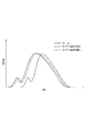
次に、図6を参照して、前面衝突時のフレーム及びキャブ(ボディ)の減速度(負の加速度)について、本実施形態と比較例と対比して説明する。比較例は、本実施形態と同様の第1ストッパ部及び第2ストッパ部を備えるが、可動部材を備えていないフレーム付車両である。図6において、実線は本実施形態及び比較例のフレームの減速度を示し、破線は本実施形態のキャブの減速度を示し、1点鎖線は比較例のキャブの減速度を示す。フレーム側からボディ側に入力する荷重は、ボディに発生する減速度に応じて変化(増減)する。 Next, with reference to FIG. 6, the deceleration (negative acceleration) of the frame and the cab (body) at the time of a frontal collision will be described in comparison with the present embodiment and the comparative example. The comparative example is a vehicle with a frame that includes the first stopper portion and the second stopper portion similar to those of the present embodiment, but does not include a movable member. In FIG. 6, the solid line indicates the deceleration of the frame of the present embodiment and the comparative example, the broken line indicates the deceleration of the cab of the present embodiment, and the one-dot chain line indicates the deceleration of the cab of the comparative example. The load input from the frame side to the body side changes (increases / decreases) according to the deceleration generated in the body.
図6に示すように、車両1の前面衝突時には、先ずフレームの減速度が増大する。すなわち、実施形態及び比較例において、フレームの減速度は、キャブの減速度の増大に先行して同様に増大する。一方、キャブの減速度の増大開始時は、可動部材を備える実施形態と可動部材を備えない比較例とで明確に相違する。すなわち、可動部材を備えない比較例の場合には、第2ストッパ部が可動空間を前方へ移動して第1ストッパ部に当接した後にキャブの減速度が増大するのに対し、可動部材を備えた実施形態の場合には、第2ストッパ部の移動開始直後に可動部材が第2ストッパ部の移動を規制してキャブの減速度が増大する。このため、フレームの減速度の増大開始からキャブの減速度の増大開始までの遅延時間(タイムラグ)を比較すると、実施形態の遅延時間は比較例の遅延時間に比べて顕著に短縮される。
As shown in FIG. 6, at the time of a frontal collision of the
以上説明したように、本実施形態によれば、車両1の通常走行時のボディ5の弾性支持を損なうことなく、車両1の前面衝突時の乗員の生存空間を十分に確保することができる。
As described above, according to the present embodiment, it is possible to sufficiently ensure the occupant's survival space during a frontal collision of the
次に、本発明の第2実施形態に係るキャブストッパ装置について、図7を参照して説明する。本実施形態は、アクチュエータの構成が第1実施形態と相違するものであり、第1実施形態と共通する構成については同一の符号を付してその説明を省略する。 Next, a cab stopper device according to a second embodiment of the present invention will be described with reference to FIG. In this embodiment, the configuration of the actuator is different from that of the first embodiment, and the same reference numerals are given to the configurations common to the first embodiment, and the description thereof is omitted.
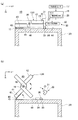
図7に示すように、本実施形態のアクチュエータ30は、ロック部材31とロック解除部32とから概略構成される。ロック部材31は、回転軸33を中心としてサイドメンバ3Rの側面44に回転自在に連結されて車幅方向外側へ延びる基部34と、基部34の先端から下方へ曲折するフック部35とを一体的に有するL状であり、可動部材13Rの上方に配置される。回転軸33の外周には、サイドメンバ3Rとロック部材31との間に介在し、ロック部材31の先端部側を下方へ付勢するコイルバネ36が回転軸33と同軸に設けられる。ロック部材31の基部34には、切欠き状の易破断部37が形成される。
As shown in FIG. 7, the
コイルバネ36に付勢されてサイドメンバ3Rの側面44から起立するロック部材31のフック部35は、格納状態の可動部材13R(第2展開部材42)の上端部に車幅方向外側から当接し、第1バネ45及び第2バネ46の付勢力に抗して可動部材13Rを格納状態に保持する(図7(a)参照)。すなわち、ロック部材31は、第1展開部材41及び第2展開部材42を第1バネ45及び第2バネ46の付勢力に抗して格納位置に保持するロック手段として機能する。
The
ロック解除部32は、ロック部材31の易破断部37に配置される火薬(図示省略)を有する。ロック解除部32は、ECU18の点火信号の受信に応じて火薬に点火して、火薬を爆発させる。火薬の爆発によりロック部材31が易破断部37で破損し、フック部35が可動部材13Rの車幅方向外側から外れ、第1バネ45及び第2バネ46の付勢力によって可動部材13R(第1展開部材41及び第2展開部材42)が展開する。すなわち、ロック解除部32は、衝突判定部20が車両1の前面衝突を検知したとき、火薬を爆発させてロック部材31による格納状態の保持を解除するロック解除手段として機能する。
The unlocking
本実施形態によれば、第1実施形態と同様に、車両1の通常走行時のボディ5の弾性支持を損なうことなく、車両1の前面衝突時の乗員の生存空間を十分に確保することができる。
According to the present embodiment, as in the first embodiment, it is possible to sufficiently ensure the occupant's living space at the time of a frontal collision of the
以上、本発明者によってなされた発明を適用した実施形態について説明したが、この実施形態による本発明の開示の一部をなす論述及び図面により本発明は限定されることはない。すなわち、この実施形態に基づいて当業者等によりなされる他の実施形態、実施例及び運用技術等は全て本発明の範疇に含まれることは勿論である。 As mentioned above, although the embodiment to which the invention made by the present inventor is applied has been described, the present invention is not limited by the discussion and the drawings that form part of the disclosure of the present invention according to this embodiment. That is, it is needless to say that other embodiments, examples, operation techniques, and the like made by those skilled in the art based on this embodiment are all included in the scope of the present invention.
例えば、第1展開部材41と第2展開部材42とから構成される可動部材13R,13Lに代えて、展開せずに単にスライド移動する単体のブロック状の可動部材を左右に設けてもよい。この場合、可動部材を、格納位置と作動位置との間で車幅方向にスライド自在にフレーム2(サイドメンバ3L,3R)又はボディ5によって支持し、格納位置から作動位置に向かってバネ等によって付勢し、通常走行時はロック部材等によって格納位置に保持すればよい。
For example, instead of the
本発明のフレーム付車両のキャブストッパ装置は、様々なフレーム付車両に適用することができる。 The cab stopper device for a vehicle with a frame according to the present invention can be applied to various vehicles with a frame.
1: フレーム付車両
2: フレーム
3L,3R: サイドメンバ
5: ボディ
6: フロアパネル
7L,7R: サイドシル
8:キャブ
9,9L,9R: マウント機構
11L,11R: 第1ストッパ部
12L,12R: 第2ストッパ部
13L,13R: 可動部材
15: 第1回転軸
16: 第2回転軸
17: 加速度センサ(衝突検知手段)
18: ECU(衝突検知手段)
19,30: アクチュエータ(作動手段)
20: 衝突判定部(衝突検知手段)
21: スライダ(ロック手段)
31: ロック部材(ロック手段)
32: ロック解除部(ロック解除手段)
40: 可動空間
41: 第1展開部材
42: 第2展開部材
45: 第1バネ(付勢手段)
46: 第2バネ(付勢手段)
48: ガス発生器(ロック解除手段)
1: Vehicle with frame 2:
18: ECU (collision detection means)
19, 30: Actuator (actuating means)
20: Collision determination unit (collision detection means)
21: Slider (locking means)
31: Lock member (lock means)
32: Unlocking part (unlocking means)
40: movable space 41: first deployment member 42: second deployment member 45: first spring (biasing means)
46: Second spring (biasing means)
48: Gas generator (lock release means)
Claims (2)
前記フレームに対して固定される第1ストッパ部と、
前記第1ストッパ部の後方に対向配置され、前記第1ストッパ部との間に所定の可動空間を区画し、前記ボディに対して固定される第2ストッパ部と、
前記フレーム又は前記ボディに支持され、前記可動空間外の格納位置から前記可動空間内の作動位置へ突出可能な可動部材と、
前記車両の前面衝突を検知する衝突検知手段と、
前記衝突検知手段が前記車両の前面衝突を検知したとき、前記可動部材を前記格納位置から前記作動位置へ突出させる作動手段と、を備え、
前記可動空間は、前記可動部材が前記格納位置に保持された格納状態で、前記第1ストッパ部に対する前記第2ストッパ部の前方への移動を許容し、
前記作動位置へ突出した作動状態の前記可動部材は、前記第1ストッパ部に対する前記第2ストッパ部の前方への移動を規制する
ことを特徴とするフレーム付車両のキャブストッパ装置。 A stopper device for a vehicle with a frame whose body is elastically supported by a frame,
A first stopper portion fixed to the frame;
A second stopper portion that is disposed opposite to the rear of the first stopper portion, defines a predetermined movable space between the first stopper portion and is fixed to the body;
A movable member supported by the frame or the body and capable of protruding from a storage position outside the movable space to an operating position within the movable space;
A collision detection means for detecting a frontal collision of the vehicle;
Operating means for projecting the movable member from the retracted position to the operating position when the collision detecting means detects a frontal collision of the vehicle,
The movable space allows the second stopper portion to move forward relative to the first stopper portion in a retracted state where the movable member is held at the retracted position;
The cab stopper device for a vehicle with a frame, wherein the movable member in the operating state protruding to the operating position restricts the forward movement of the second stopper portion relative to the first stopper portion.
前記可動部材は、第1回転軸を中心として前記フレーム又は前記ボディに回転自在に支持される第1展開部材と、第2回転軸を中心として前記第1展開部材に回転自在に連結される第2展開部材とを有し、
前記格納状態では、前記第1展開部材と前記第2展開部材とが前記可動空間の近傍で直線状に重なり、
前記突出状態では、前記第1展開部材が前記第1回転軸を中心として前記格納位置から傾動するとともに、前記第2展開部材が前記第2回転軸を中心として前記第1展開部材に対して傾動して、前記第1展開部材と前記第2展開部材とが前記可動空間内でX状に交叉して展開し、
前記作動手段は、前記格納位置の前記第1展開部材及び前記第2展開部材を前記作動位置へ付勢する付勢手段と、前記第1展開部材及び前記第2展開部材を前記付勢手段の付勢力に抗して前記格納位置に保持するロック手段と、前記衝突検知手段が前記車両の前面衝突を検知したとき、前記ロック手段による前記格納状態の保持を解除するロック解除手段とを有する
ことを特徴とするフレーム付車両のキャブストッパ装置。 The stopper device according to claim 1,
The movable member includes a first deploying member rotatably supported by the frame or the body about a first rotation axis, and a first unfolding member rotatably coupled to the first deployment member about a second rotation axis. 2 deployment members,
In the retracted state, the first deployment member and the second deployment member overlap linearly in the vicinity of the movable space,
In the protruding state, the first deployment member tilts from the retracted position about the first rotation axis, and the second deployment member tilts relative to the first deployment member about the second rotation axis. Then, the first deployment member and the second deployment member are deployed in an X shape within the movable space,
The actuating means includes a biasing means for biasing the first deployment member and the second deployment member at the retracted position to the actuation position, and the first deployment member and the second deployment member of the biasing means. Locking means for holding the storage position against the urging force, and unlocking means for releasing the storage state held by the locking means when the collision detection means detects a frontal collision of the vehicle. A cab stopper device for a vehicle with a frame.
Priority Applications (2)
| Application Number | Priority Date | Filing Date | Title |
|---|---|---|---|
| JP2015126669A JP2017007577A (en) | 2015-06-24 | 2015-06-24 | Cab stopper device of vehicle with frame |
| PCT/JP2016/067385 WO2016208423A1 (en) | 2015-06-24 | 2016-06-10 | Cab stopper device for frame-equipped vehicle |
Applications Claiming Priority (1)
| Application Number | Priority Date | Filing Date | Title |
|---|---|---|---|
| JP2015126669A JP2017007577A (en) | 2015-06-24 | 2015-06-24 | Cab stopper device of vehicle with frame |
Publications (1)
| Publication Number | Publication Date |
|---|---|
| JP2017007577A true JP2017007577A (en) | 2017-01-12 |
Family
ID=57585577
Family Applications (1)
| Application Number | Title | Priority Date | Filing Date |
|---|---|---|---|
| JP2015126669A Pending JP2017007577A (en) | 2015-06-24 | 2015-06-24 | Cab stopper device of vehicle with frame |
Country Status (2)
| Country | Link |
|---|---|
| JP (1) | JP2017007577A (en) |
| WO (1) | WO2016208423A1 (en) |
Family Cites Families (3)
| Publication number | Priority date | Publication date | Assignee | Title |
|---|---|---|---|---|
| JPH0672786U (en) * | 1993-03-29 | 1994-10-11 | 日産車体株式会社 | Car body structure |
| JP3508317B2 (en) * | 1995-08-29 | 2004-03-22 | いすゞ自動車株式会社 | Vehicle body stopper structure |
| JP3653932B2 (en) * | 1997-06-06 | 2005-06-02 | いすゞ自動車株式会社 | Body structure of vehicle with frame |
-
2015
- 2015-06-24 JP JP2015126669A patent/JP2017007577A/en active Pending
-
2016
- 2016-06-10 WO PCT/JP2016/067385 patent/WO2016208423A1/en active Application Filing
Also Published As
| Publication number | Publication date |
|---|---|
| WO2016208423A1 (en) | 2016-12-29 |
Similar Documents
| Publication | Publication Date | Title |
|---|---|---|
| JP5776648B2 (en) | Crew protection device | |
| JP5743798B2 (en) | Strap holding device and airbag device | |
| JP6364700B2 (en) | Airbag device | |
| JP6350367B2 (en) | Vehicle airbag system | |
| JP5862435B2 (en) | Vehicle control device | |
| JP6314897B2 (en) | Driver's seat airbag device for vehicle | |
| JP4999843B2 (en) | Side airbag unit for automobile | |
| JP5962602B2 (en) | Front seat airbag system | |
| CN111660994B (en) | Airbag device for vehicle, control method for airbag device for vehicle, and storage medium | |
| JP6136871B2 (en) | Control device for pedestrian protection device | |
| JP6424796B2 (en) | Vehicle airbag device | |
| US10391964B2 (en) | Vehicle occupant protection apparatus | |
| JP2007153224A (en) | Method of deploying airbag for automobile | |
| JP2021037923A (en) | Occupant protection device | |
| WO2016208423A1 (en) | Cab stopper device for frame-equipped vehicle | |
| JP6826473B2 (en) | Crew protection device | |
| JP3883982B2 (en) | Automotive safety devices | |
| JP6937144B2 (en) | Crew protection device | |
| JP4822102B2 (en) | Vehicle shock absorption structure | |
| JPH06239195A (en) | Vehicular air bag device | |
| JP6989400B2 (en) | Vehicle shock absorber | |
| JP5223251B2 (en) | Vehicle occupant protection device | |
| JP2016124531A (en) | Seat structure of vehicle | |
| JP6836436B2 (en) | Crew protection device | |
| JP6842330B2 (en) | Crew protection device |