JP2017005354A - Glass antenna for vehicle and rear window glass with antenna for vehicle - Google Patents
Glass antenna for vehicle and rear window glass with antenna for vehicle Download PDFInfo
- Publication number
- JP2017005354A JP2017005354A JP2015114724A JP2015114724A JP2017005354A JP 2017005354 A JP2017005354 A JP 2017005354A JP 2015114724 A JP2015114724 A JP 2015114724A JP 2015114724 A JP2015114724 A JP 2015114724A JP 2017005354 A JP2017005354 A JP 2017005354A
- Authority
- JP
- Japan
- Prior art keywords
- antenna
- glass
- antenna element
- vehicle
- heater
- Prior art date
- Legal status (The legal status is an assumption and is not a legal conclusion. Google has not performed a legal analysis and makes no representation as to the accuracy of the status listed.)
- Withdrawn
Links
Images


Classifications
-
- H—ELECTRICITY
- H01—ELECTRIC ELEMENTS
- H01Q—ANTENNAS, i.e. RADIO AERIALS
- H01Q1/00—Details of, or arrangements associated with, antennas
- H01Q1/27—Adaptation for use in or on movable bodies
- H01Q1/32—Adaptation for use in or on road or rail vehicles
- H01Q1/3208—Adaptation for use in or on road or rail vehicles characterised by the application wherein the antenna is used
-
- B—PERFORMING OPERATIONS; TRANSPORTING
- B60—VEHICLES IN GENERAL
- B60J—WINDOWS, WINDSCREENS, NON-FIXED ROOFS, DOORS, OR SIMILAR DEVICES FOR VEHICLES; REMOVABLE EXTERNAL PROTECTIVE COVERINGS SPECIALLY ADAPTED FOR VEHICLES
- B60J1/00—Windows; Windscreens; Accessories therefor
- B60J1/20—Accessories, e.g. wind deflectors, blinds
-
- H—ELECTRICITY
- H01—ELECTRIC ELEMENTS
- H01Q—ANTENNAS, i.e. RADIO AERIALS
- H01Q1/00—Details of, or arrangements associated with, antennas
- H01Q1/12—Supports; Mounting means
- H01Q1/1271—Supports; Mounting means for mounting on windscreens
- H01Q1/1278—Supports; Mounting means for mounting on windscreens in association with heating wires or layers
-
- H—ELECTRICITY
- H01—ELECTRIC ELEMENTS
- H01Q—ANTENNAS, i.e. RADIO AERIALS
- H01Q1/00—Details of, or arrangements associated with, antennas
- H01Q1/27—Adaptation for use in or on movable bodies
- H01Q1/32—Adaptation for use in or on road or rail vehicles
Abstract
Description
本発明は、垂直偏波を受信する車両用ガラスアンテナ及び車両用アンテナを備えた後部窓ガラスに関する。 The present invention relates to a vehicle glass antenna that receives vertically polarized waves and a rear window glass that includes the vehicle antenna.
近年、デジタルオーディオ放送(Digital Audio Broadcasting:DAB)を受信可能な車両用ガラスアンテナが知られている。DABは、174〜240MHzのband III(バンドIII)と1452〜1492MHzのL−band(Lバンド)の2つの異なる周波数帯から構成されている。 In recent years, glass antennas for vehicles capable of receiving digital audio broadcasting (DAB) have been known. DAB is composed of two different frequency bands, band III (band III) of 174 to 240 MHz and L-band (L band) of 1452 to 1492 MHz.
このDABは垂直方向に偏向しているため、DAB用アンテナは垂直成分が長いパターンで構成されていた。例えば、図1に示した特許文献1の例では、垂直方向に偏向し、周波数の離れた2つの帯域を含むDABを受信するため、垂直パターンで構成された2つのアンテナエレメントを含むガラスアンテナ30がリヤガラス80へ設置されている。
Since this DAB is deflected in the vertical direction, the DAB antenna has a pattern with a long vertical component. For example, in the example of
また、一般的に視界を確保するために電熱線42を用いて結露を取り除くデフォッガ(防曇用加熱線条)4が設けられている。
Further, in general, a defogger (antifogging heating wire) 4 for removing condensation using a
ところが、上記特許文献1の構成のアンテナは、リヤガラス80においてデフォッガ40が占める割合が小さい、取付角度が小さい(例えば、地面に対して10〜50°程度)リヤガラスを備えるセダン等の車に適用されることを前提していた。リヤガラスの取付角度が小さいと、所定の大きさのデフォッガを設けたとしても、窓ガラスに余白があり(図1では上部)、その余白部に縦方向(上下方向)のアンテナエレメントを含むアンテナ30を設けることができた。
However, the antenna having the configuration of
しかし、跳ね上げ式、または横開き式の「バックドア」(背面ドア)を設けた車種であるハッチバックタイプの車では、リヤガラスの取付角度が大きくなる(例えば、40°〜90°)。窓の取付角度が大きくなるに連れ、窓ガラスの縦寸法が小さくなり、防雲による良好な視界を確保するためにデフォッガが、窓全体に対して占める割合が大きくなる。デフォッガがリヤガラスで占める割合が大きくなると、熱線以外の余白部が小さくなるため、リヤガラスにアンテナの設置スペースが確保しづらかった。 However, in a hatchback type vehicle that is a vehicle type provided with a flip-up type or side-opening type “back door” (rear door), the mounting angle of the rear glass becomes large (for example, 40 ° to 90 °). As the window mounting angle increases, the vertical dimension of the window glass decreases, and the ratio of the defogger to the entire window increases in order to ensure a good field of view due to cloud protection. When the proportion of the defogger in the rear glass increases, the blank space other than the heat rays decreases, making it difficult to secure the antenna installation space on the rear glass.
そこで、本発明は上記事情に鑑み、窓ガラスに対してデフォッガが大きな割合を占めていても、垂直偏波であるDABの受信感度を確保することができる、車両用ガラスアンテナの提供を目的とする。 Therefore, in view of the above circumstances, the present invention aims to provide a glass antenna for a vehicle that can secure DAB reception sensitivity that is vertically polarized even if the defogger occupies a large proportion of the window glass. To do.
上記課題を解決するため、本発明は、通電加熱式のデフォッガが車両の後部窓ガラスに設けられ、DABの垂直偏波を受信する車両用ガラスアンテナであって、前記デフォッガは、前記後部窓ガラスの下部側から上部側まで水平方向に沿って延在する複数のヒーター線と、前記後部窓ガラスの左右両端部側において上下方向に延在し、前記複数のヒーター線に給電する複数のバスバーとを有し、前記車両用ガラスアンテナは、前記後部窓ガラスの少なくとも左右何れか一方の端部側で、前記デフォッガよりも上部又は下部に設けられ、前記車両用ガラスアンテナは、給電点と、前記給電点から略水平方向に延在する第1のアンテナエレメントと、を備えており、受信する周波数帯域の中心周波数における空気中の波長をλ、ガラス波長短縮率をk、前記後部窓ガラス上での波長をλg=λ・k、としたとき、前記第1のアンテナエレメントの導体長が(1/6)・λg以下であり、前記第1のアンテナエレメントと、前記ヒーター線のうち最外に設けられ、前記第1のアンテナエレメントと最近接する第1のヒーター線との距離が(1/40)・λg以下である、ことを特徴とする車両用ガラスアンテナを提供するものである。 In order to solve the above-mentioned problem, the present invention provides a glass antenna for a vehicle in which an electrically heated defogger is provided on a rear window glass of a vehicle and receives vertical polarization of DAB, and the defogger includes the rear window glass. A plurality of heater wires extending in the horizontal direction from the lower side to the upper side of the first window, and a plurality of bus bars extending in the vertical direction on the left and right ends of the rear window glass, and supplying power to the plurality of heater wires. The vehicle glass antenna is provided on the upper or lower side of the defogger on at least one of the left and right end sides of the rear window glass, the vehicle glass antenna includes a feeding point, and A first antenna element extending in a substantially horizontal direction from the feeding point, and λ is the wavelength in the air at the center frequency of the receiving frequency band, and the glass wavelength reduction rate k, where the wavelength on the rear window glass is λg = λ · k, the conductor length of the first antenna element is (1/6) · λg or less, and the first antenna element, A glass antenna for a vehicle, characterized in that a distance between the outermost heater wire and the first heater element closest to the first antenna element is (1/40) · λg or less. It is to provide.
一態様によれば、車両用ガラスアンテナは、窓ガラスに対してデフォッガが大きな割合を占めていても、垂直偏波であるDABの受信感度を確保することができる。 According to one aspect, the vehicular glass antenna can ensure the reception sensitivity of DAB that is vertically polarized even if the defogger occupies a large proportion of the window glass.
以下、図面を参照して、本発明を実施するための最良の形態の説明を行う。なお、形態を説明するための図面において、方向について特に記載しない場合には図面上での方向をいうものとする。また、それらの図面は、窓ガラスの面を対向して見たときの図であって、窓ガラスが車両に取り付けられた状態での車内視(又は、車外視)の図であり、図面上での左右方向(横方向)が水平方向に相当し、上下方向が垂直方向に相当する。しかし、車外視の図として参照してもよい。例えば、窓ガラスが車両の後部に取り付けられるリヤガラスである場合、図面上での左右方向が車幅方向に相当する。また、本発明に係る窓ガラスは、主に、車両の後部に取り付けられるリヤガラスである。また、平行、直角などの方向は、本発明の効果を損なわない程度のズレを許容するものである。 The best mode for carrying out the present invention will be described below with reference to the drawings. Note that in the drawings for describing the embodiments, the directions on the drawings are used unless otherwise specified. In addition, these drawings are views when the surfaces of the window glass are viewed to face each other, and are views of the interior of the vehicle (or the exterior of the vehicle) with the window glass attached to the vehicle. The left / right direction (lateral direction) in FIG. 1 corresponds to the horizontal direction, and the up / down direction corresponds to the vertical direction. However, it may be referred to as a vehicle external view. For example, when the window glass is a rear glass attached to the rear portion of the vehicle, the left-right direction on the drawing corresponds to the vehicle width direction. Further, the window glass according to the present invention is mainly a rear glass attached to the rear part of the vehicle. Further, the directions such as parallel and right angles allow a deviation that does not impair the effects of the present invention.
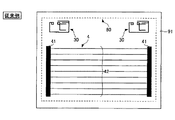
また、本発明において、窓ガラスは車両ボディの開口部を覆う一例である。窓ガラスは板状部材であって、素材はガラスに限られず、樹脂、フィルム等であってもよい。後部窓ガラス60(窓ガラス又はリヤガラスともいう。)は、車両筺体のフランジによって形成される筺体開口部(開口部ともいう)に取り付けられている。窓ガラス60の外周縁は図2の点線で図示されている。符号71は、車体の窓開口部を形成する車体フランジの端部を示している。
Moreover, in this invention, a window glass is an example which covers the opening part of a vehicle body. The window glass is a plate-like member, and the material is not limited to glass, and may be a resin, a film, or the like. The rear window glass 60 (also referred to as window glass or rear glass) is attached to a chassis opening (also referred to as an opening) formed by a flange of the vehicle chassis. The outer peripheral edge of the
図2は、本発明の一実施形態であるガラスアンテナ(車両用ガラスアンテナ、車両用アンテナともいう)10Bの平面図である。車両用ガラスアンテナ(窓ガラスにプリント、埋め込み、貼り付け等により組み込まれたアンテナ)は、車両用の窓ガラス60に平面的な導体パターンとして設けられる給電点及びアンテナ導体を含んで構成される。
FIG. 2 is a plan view of a glass antenna (also referred to as a vehicle glass antenna or a vehicle antenna) 10B according to an embodiment of the present invention. A glass antenna for a vehicle (an antenna incorporated in a window glass by printing, embedding, or sticking) includes a feeding point and an antenna conductor provided as a planar conductor pattern on the
ガラスアンテナ10Bは、給電点(芯線側給電点)8と、該給電点8を起点に、略水平方向に延在するエレメント(第1の線条エレメント)1を備えている。アンテナエレメント1でもLバンドの電波を受信できるが、Lバンドの利得が低いとき、図5に示すように、アンテナエレメント2が備えられてもよい。
The
リヤガラス(後部窓ガラス)60は、金属製のバックドア又は車体ボディ70に形成されたフランジ71(あるいは樹脂製のパネル73)に取り付けられる外周部61を有する窓ガラスである。リヤガラス60の周縁は、点線で図示されている。
The rear glass (rear window glass) 60 is a window glass having an outer
図2において72Bは、後方を視認するための開口部(第2の開口部)を示す。金属製のバックドア又は車体ボディ70Bは広く開口しており(第1の開口部74)、該開口部74に重ねて樹脂製のパネル73が形成され、樹脂製のパネル73が後方を視認するために開口している(第2の開口部72B)。リヤガラス60は、バックドア又は車体ボディ70Bに取り付けられた樹脂製のパネル73に取り付けられ、開口部(第2の開口部)72Bを覆う。
In FIG. 2, 72B shows the opening part (2nd opening part) for visually recognizing back. The metal back door or the
あるいは、図3において符号72は、後方を視認するための開口部を示す。該開口部72が、リヤガラス60の窓枠であるフランジ71を形成する。
Or the code |
図3において、開口部72は、金属製のバックドア(ハッチバック車)または車体ボディ(セダン)が開口する縁部で形成される。リヤガラス60は、バックドア又は車体ボディ70に取り付けられ、開口部72を覆う。
In FIG. 3, the
図4〜図7は、図3と同様の構成が示されているが、図2に示すように樹脂製のパネル73を設ける構成にしてもよい。 4 to 7 show the same configuration as that in FIG. 3, a resin panel 73 may be provided as shown in FIG. 2.
リヤガラス60には、複数の並走するヒーター線22とヒーター線22に給電する複数の帯状のバスバー21とを有するデフォッガ(DEF)20が設けられてよい。デフォッガ20に構成されるヒーター線22及びバスバー21は、通電加熱式の導電パターンである。図2には、ガラスアンテナ10Bが、リヤガラス60においてデフォッガ20よりも下側の余白領域に設けられている場合が示されている。
The
ガラスアンテナ10Bは、窓ガラスの表面に平面的に設けられ、例えば、銀ペースト等の、導電性金属を含有するペーストを窓ガラスの車内側表面にプリントし、焼付けて形成される。しかし、この形成方法に限定されず、銅等の導電性物質からなる、線状体又は箔状体を、窓ガラスの車内側表面又は車外側表面に形成してもよく、窓ガラスに接着剤等により貼付してもよく、窓ガラスの内部に設けてもよい。窓ガラスに配置されたデフォッガ20についても同様である。
The
ガラスアンテナ10Bは、窓ガラスの右下方に位置する給電点8と、給電点8に接続されるアンテナ導体(アンテナエレメント)1とを有する。
The
給電点8は、同軸ケーブルまたはAV線にアンテナ導体1を接続する。給電点8は、リヤガラス60がフランジ71に取り付けられたときに、フランジ71の角部近傍に位置するようにリヤガラス60に設けられた電極であるとよい。
The
図2において、窓ガラス60の面上に黒色の遮蔽膜(不図示)を形成し、この遮蔽膜の上にアンテナ導体の一部分又は全体を設けてもよい。遮蔽膜は黒色セラミックス膜等のセラミックスが挙げられる。この場合、窓ガラスの車外側から見ると、遮蔽膜により遮蔽膜上に設けられているアンテナ導体の部分が車外から見えなくなり、デザインの優れた窓ガラスとなる。
In FIG. 2, a black shielding film (not shown) may be formed on the surface of the
図2に示すガラスアンテナ10B(車両用アンテナの一例)は、単極(モノポール)アンテナであって、アンテナ導体により得られる受信信号が芯線側(ホット側)の給電点8から取り出し可能になっており、その受信信号が受信機(不図示)に伝達される。単極アンテナの場合、窓ガラス60が取り付けられる車両の車体開口部やその近傍部がグランドとして使用可能な部位であるとよい(いわゆるボディーアースがとれる)。
A
ガラスアンテナ10Bは、バックドア又は車体ボディ70(あるいは樹脂製のパネル73)の側縁部の近傍に給電点8が配置される場合に好適な形態である。
The
給電点8は、受信機に接続される給電線が電気的に接続される給電点(給電部)である。給電線としてAV線を用いる場合は、給電点8と車両側に設置された増幅器とを接続し、増幅器のグランドにボディーアースをとる。このとき、AV線と給電点8とを電気的に接続するためのコネクタを給電点8に実装する構成にすることによって、AV線を給電点8に取り付けしやすくなる。
The
しかし、本発明に係るガラスアンテナ10Bにおいて、給電点は単極に限られず、2つの給電点を備えた双極でもよい。例えば、図3〜図7に示す本願の実施形態のように、窓ガラス60に、図3に示した接地側給電点9を設けてもよい。給電点8(芯線側給電点)に同軸ケーブルの内部導体(芯線)を電気的に接続し、同軸ケーブルの外部導体と接地側給電点9とが電気的に接続される。同軸ケーブルと給電点8及び接地側給電点9とを電気的に接続するためのコネクタを給電点8及び接地側給電点9に実装する構成にすることによって、同軸ケーブルを給電点8及び接地側給電点9に取り付けしやすくなる。
However, in the
接地側給電点9は、給電点8及び給電点8に電気的に接続されるアンテナエレメント1、2等のアンテナ導体に接しないように、給電点8の周辺に近接して配置されていればよい。図3の場合、接地側給電点9は、給電点8の右側に、給電点8に所定距離離間して配置されている。接地側給電点9は、例えば、図4、6の実施形態の如く、給電点8の左側に配置されていてもよい。
If the ground-
給電点8に実装されるコネクタに給電点8から取り出せる受信信号を増幅するための増幅回路が内蔵されている場合には、その増幅回路のグランドを同軸ケーブルの外部導体等のグランド部位に電気的に接続し、その増幅回路の入力側に給電点8が電気的に接続され、その増幅回路の出力側に同軸ケーブルの内部導体が接続されるとよい。
When an amplifier circuit for amplifying a received signal that can be extracted from the
給電点8の形状は、給電点8に直接取り付けられる給電線の先端形状又は給電点8と給電線とを接続するための接続部材の形状(例えば、コネクタの実装面や接触端子の形状)に応じて決めるとよい。例えば、正方形、略正方形、長方形、略長方形などの方形状や多角形状が実装上好ましい。なお、円、略円、楕円、略楕円などの円状でもよい。
The shape of the
図3に示した接地側給電点9の形状についても、給電点8と同様にどのような形状であってもよい。また、給電点8と接地側給電点9との離間距離についても、給電点8及び接地側給電点9に直接取り付けられる給電線の先端形状又は給電点8及び接地側給電点9と給電線とを接続するための接続部材の形状(例えば、コネクタの実装面や接触端子の形状)に応じて決めるとよい。
The shape of the ground-
図2では、正方形状の給電点8を示している。給電点8の左辺のアンテナエレメントとの接続点が位置する。あるいは、図4、6のように、アンテナエレメント1Aは給電点8の左辺に接続してもよい。
In FIG. 2, a
後述する本発明の実施形態において、アンテナ導体からなる導体層を合成樹脂製フィルムの内部又はその表面に設け、導体層付き合成樹脂製フィルムを窓ガラスの車内側表面又は車外側表面に形成してガラスアンテナとしてもよい。さらに、アンテナ導体が形成されたフレキシブル回路基板を窓ガラスの車内側表面又は車外側表面に形成してガラスアンテナとしてもよい。 In an embodiment of the present invention to be described later, a conductor layer made of an antenna conductor is provided inside or on the surface of the synthetic resin film, and the synthetic resin film with a conductor layer is formed on the vehicle inner surface or the vehicle outer surface of the window glass. It may be a glass antenna. Furthermore, it is good also as a glass antenna by forming the flexible circuit board in which the antenna conductor was formed in the vehicle inner surface or vehicle outer surface of a window glass.
<第1の実施形態>
図2及び図3は、本発明の第1の実施形態である車両用アンテナが設置されたリヤガラスの全体平面図である。
<First Embodiment>
2 and 3 are overall plan views of the rear glass on which the vehicle antenna according to the first embodiment of the present invention is installed.
詳しくは、帯域幅が広く垂直偏波のDABの周波数帯のうち、帯域が低い第1の周波数帯(バンドIII)の中心周波数における空気中の波長をλ01とし、窓ガラスの波長短縮率をkとし、窓ガラス上での波長をλg1=λ01・kとする。このとき、給電点8から第1のアンテナエレメント1の先端までの導体長(=最長経路長)L1が、導体長が1/6・λg1以下であると、第1の周波数帯のアンテナ得向上の点で好ましい結果が得られる。また、(1/8)・λg1以下であるとさらに好ましい。
Specifically, out of the DAB frequency band with wide bandwidth and vertical polarization, the wavelength in the air at the center frequency of the first frequency band (band III) having a low band is λ 01, and the wavelength reduction rate of the window glass is k and the wavelength on the window glass is λ g1 = λ 01 · k. At this time, if the conductor length (= longest path length) L1 from the
例えば、バンドIII(174〜240MHz)の中心周波数は207MHzである。したがって、バンドIIIのアンテナ利得を向上させたい場合、電波の速さを3.0×10⁸m/sとし、波長短縮率kを0.64とすると、導体長L1を、155mm以下、さらに好ましくは116mm以下に調整するとよい。詳細は実施例1で説明する。 For example, the center frequency of band III (174 to 240 MHz) is 207 MHz. Therefore, when it is desired to improve the antenna gain of band III, when the speed of radio waves is set to 3.0 × 10 8 m / s and the wavelength shortening rate k is set to 0.64, the conductor length L1 is more preferably 155 mm or less. Is preferably adjusted to 116 mm or less. Details will be described in the first embodiment.
すなわち、ガラスアンテナ10の形状によれば、第1のアンテナエレメント1の導体長(最長経路長)L1は第1の放送周波数帯で共振する長さに基づいて設定されると好ましい。
That is, according to the shape of the
なお、本実施形態においては、水平に延伸するアンテナエレメント1について説明したが、延在方向は水平に限られない。例えば、最下部のヒーター線が傾斜している場合、または湾曲しているその傾斜また平行に沿うように設置されればよい。
In addition, in this embodiment, although the
また、平行又は垂直は、±50°程度の傾きの誤差を含んでもよい。あるいはアンテナエレメントは、上記の導体長の範囲で、給電点と接触しない終端部が、最下部又は最上部のヒーター線と接触せず、窓ガラス60の全ての縁部に接触しない範囲で屈曲又は湾曲していてもよい。
Parallel or vertical may include a tilt error of about ± 50 °. Alternatively, the antenna element is bent or bent in a range in which the terminal portion that does not contact the feeding point does not contact the lowermost or uppermost heater wire and does not contact all the edges of the
ここで、DABは垂直偏波であるため、適切な導体長の縦のアンテナエレメントを設置すると、受信利得が向上することが知られている。 Here, since DAB is vertically polarized, it is known that the reception gain is improved by installing a vertical antenna element having an appropriate conductor length.
しかし、図2のように、デフォッガ20がリヤガラスで大部分が占めていると、ガラスアンテナとして、縦方向に延在するアンテナエレメントが配置できない。また、水平方向においては、窓の横幅(Ww)のほぼ全域(Dw)に、デフォッガ20が設けられており、デフォッガの側辺(バスバー)の外側には、アンテナが配置される程度の空間はほぼ無い。
However, as shown in FIG. 2, when the
そこで、本発明の実施形態では、水平方向に延在するアンテナエレメントを、デフォッガの水平方向に延在するヒーター線と容量結合させることで、垂直偏波であるDABを受信するように、構成されている。デフォッガはアンテナとの容量結合によって、アンテナの一部として機能しうる。 Therefore, in the embodiment of the present invention, the antenna element extending in the horizontal direction is capacitively coupled to the heater line extending in the horizontal direction of the defogger so as to receive DAB that is vertically polarized. ing. The defogger can function as a part of the antenna by capacitive coupling with the antenna.
このような構成により、ガラスアンテナとして縦方向のアンテナエレメントを設けなくても、垂直偏波であるDABを受信することが可能である。ただし、容量結合したアンテナエレメント1で受信したDABの垂直偏波の受信特性を微調整するために縦方向のアンテナエレメントを設けてもよい。
With such a configuration, it is possible to receive DAB that is vertically polarized without providing a vertical antenna element as a glass antenna. However, a vertical antenna element may be provided to finely adjust the reception characteristics of DAB vertical polarization received by the capacitively coupled
本発明の実施形態において、上述の帯域が低い第1の周波数帯の中心周波数における空気中の波長をλ01とし、窓ガラスの波長短縮率をkとし、窓ガラス上での波長をλg1=λ01・kとする。このとき、ヒーター線22lから第1のアンテナエレメント1までの距離D1が、(1/40)・λg1以下であれば、第1の周波数帯のアンテナ利得向上の点で好ましい結果が得られる。また、(1/48)・λg1以下であればさらに好ましい。
In the embodiment of the present invention, the wavelength in the air at the center frequency of the first frequency band having the above-mentioned low band is λ 01 , the wavelength reduction rate of the window glass is k, and the wavelength on the window glass is λ g1 = It is assumed that λ 01 · k. The distance D1 from the heater wire 22l to the
例えば、バンドIII(174〜240MHz)の中心周波数は207MHzである。したがって、バンドIIIのアンテナ利得を向上させたい場合、電波の速さを3.0×10⁸m/sとし、波長短縮率kを0.64とすると、距離を、23.2mm以下、さらに好ましくは19.3mm以下に調整するとよい。詳細は実施例2で説明する。 For example, the center frequency of band III (174 to 240 MHz) is 207 MHz. Therefore, when it is desired to improve the antenna gain of band III, when the speed of radio waves is set to 3.0 × 10 8 m / s and the wavelength shortening rate k is set to 0.64, the distance is more preferably 23.2 mm or less. May be adjusted to 19.3 mm or less. Details will be described in the second embodiment.
ここで、開口部72は、金属製のバックドアまたは車体ボディが開口する縁部、あるいは、金属製のバックドアまたは車体ボディの開口部の内側に取り付けられる樹脂製のパネルの縁部で形成されている。
Here, the
アンテナエレメントは金属で形成されるため、金属に触れると性能が低下する。しかし、開口部72が金属の縁部である場合はもちろん、リヤガラスが樹脂製のパネルの縁部を覆って張り付ける際に導電性能を備える接着剤を用いているため、ガラスアンテナの特性に悪影響を与える恐れがある。
Since the antenna element is made of metal, the performance deteriorates when the antenna element is touched. However, when the
そのため、開口部を金属又は樹脂のいずれの材料で構成しても、ガラスアンテナが接触する受信性能が低下するおそれがあるため、ガラスアンテナは開口部の内側に構成することが好適である。 For this reason, even if the opening is made of either metal or resin, there is a risk that the reception performance with which the glass antenna comes into contact may be lowered. Therefore, the glass antenna is preferably formed inside the opening.
ここで、市販の車両の窓の大きさについて説明する。普通車(SUV、RV車以外の、ワゴンタイプ又はセダンタイプの中型車、小型車等)だと、後方の形状が窓ガラスの見た目の高さ(垂直高さ)は、後方の形状に依らず、260〜330mm程度である。これに対し、中型車であってもSUV(RV)だと車高が高く370〜400mm程度である。 Here, the size of the window of a commercially available vehicle will be described. For ordinary vehicles (other than SUV, RV vehicles, wagon-type or sedan-type medium-sized vehicles, small-sized vehicles, etc.), the rear shape is the height of the window glass (vertical height), regardless of the rear shape. It is about 260-330 mm. On the other hand, even if it is a medium-sized vehicle, the vehicle height is high in the case of SUV (RV), which is about 370 to 400 mm.
ここで、車両の後方の形状がハッチバック(ワゴンタイプ、SUV等)であると、セダンよりも地面に対する窓ガラスの取付角度が大きい分、窓のガラスの高さ(縦寸法)が短い。例えば、セダン形状だと、窓ガラスの縦寸法は、650〜700mm程度である)が、ハッチバック形状だと、窓ガラスの寸法は350〜500mm程度である。 Here, when the rear shape of the vehicle is a hatchback (wagon type, SUV, etc.), the height (vertical dimension) of the glass of the window is shorter because the attachment angle of the window glass to the ground is larger than that of the sedan. For example, in the case of a sedan shape, the vertical dimension of the window glass is about 650 to 700 mm), but in the case of a hatchback shape, the dimension of the window glass is about 350 to 500 mm.
良好な視野の確保するため、デフォッガは所定量必要なので、窓ガラスの縦寸法が短くなると、その分デフォッガが窓ガラスに占める面積が大きくなる。例えばハッチバック車では、デフォッガが窓ガラスの開口部に占める割合は75〜95%程度、セダン車は50〜70%程度である。 Since a predetermined amount of defogger is necessary to ensure a good field of view, the area occupied by the defogger in the window glass increases as the vertical dimension of the window glass decreases. For example, in hatchback cars, the ratio of defogger to the window glass opening is about 75 to 95%, and for sedan cars is about 50 to 70%.
従って、上方及び下方の空白領域(アンテナ設置可能領域)の合計の割合は、セダン車では、30〜50%であるが、ハッチバック車では5〜25%に限られる。 Accordingly, the total ratio of the upper and lower blank areas (areas where antennas can be installed) is 30 to 50% for sedan vehicles, but is limited to 5 to 25% for hatchback vehicles.
よって、デフォッガと近接させて配置し、設置面積が小さい小型の本発明のガラスアンテナは、後方がハッチバック車のバックドアに設置されたリヤガラスに設けると、より効果的である。 Therefore, the small glass antenna of the present invention, which is arranged close to the defogger and has a small installation area, is more effective when the rear side is provided on the rear glass installed on the back door of the hatchback vehicle.
本実施形態では、窓ガラスの開口部72とバスバーの下端部との距離は、アンテナパターンの全長よりも短い(高さがない)。即ち、ヒーター線22lと該ヒーター線22lに対向するリヤガラス60の開口部72の下縁又は上縁との距離が、第1のアンテナエレメント1の導体長よりも短い。よって、上記の導体長を備える第1のアンテナエレメント1は、垂直に延在させることができない。
In the present embodiment, the distance between the opening 72 of the window glass and the lower end of the bus bar is shorter (no height) than the entire length of the antenna pattern. That is, the distance between the heater wire 22l and the lower or upper edge of the
本実施形態では、水平パターンのアンテナをデフォッガと近接して設けることでDABの垂直偏波を受信できるため、リヤガラスにおけるデフォッガの占有範囲を削減することなく(例えば、切欠き部等を設けることなく)ガラスアンテナとして機能させることができる。 In this embodiment, the DAB vertical polarization can be received by providing a horizontal pattern antenna close to the defogger. Therefore, without reducing the occupation range of the defogger in the rear glass (for example, without providing a notch or the like). ) Can function as a glass antenna.
なお、給電点は目立たたない部分に配置すると好ましいため、角部に配置されるため、第1のアンテナエレメント1は、窓ガラスの幅方向の中心線12の方向に向かって略水平に延在する。
In addition, since it is preferable to arrange | position a feeding point in the part which is not conspicuous, since it arrange | positions in a corner | angular part, the
また、周波数特性の調整などのためにアンテナエレメントを追加する場合は、主に受信を行う第1、第2のアンテナエレメント1,2及び給電点8、9が開口部72の内側に設けられていればよく、調整用エレメントは開口部72の外のフランジ71(又は図2の樹脂パネル73)へはみ出してもよい。
In addition, when an antenna element is added for adjusting frequency characteristics, the first and
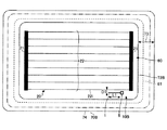
<第2の実施形態>
図4は、本発明の第2の実施形態である車両用アンテナが設置されたリヤガラスの全体平面図である。
<Second Embodiment>
FIG. 4 is an overall plan view of a rear glass on which a vehicle antenna according to a second embodiment of the present invention is installed.
本実施形態は、図2に示すガラスアンテナ10の設置位置を上方にし、左右を反転させたものである。本実施形態において、ガラスアンテナ10Aの第1のアンテナエレメント1Aは、デフォッガ20の最上部のヒーター線(第1のヒータ線)22uと近接して設置されている。この場合であっても、図3と同様の効果を奏する。
In the present embodiment, the installation position of the
なお、図3〜図7では、接地側給電点9A(9)を設置する構成を示しているが、図2に示すように、給電点を単極に構成してもよい。
3 to 7 show a configuration in which the ground-
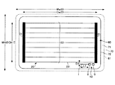
<第3の実施形態>
図5は、本発明の第3の実施形態である車両用アンテナが設置されたリヤガラスの全体平面図である。
<Third Embodiment>
FIG. 5 is an overall plan view of a rear glass on which a vehicle antenna according to a third embodiment of the present invention is installed.
本実施形態は、デフォッガ20において、縦方向(窓表面方向)に延伸するヒーター縦線23を設けている。ヒーター縦線23は、アンテナと最近接し、容量結合している最下部のヒーター線(第1のヒータ線)22lと接触して設置されている。
In the present embodiment, the
上述のように、DABは垂直偏波であるので、縦方向のアンテナエレメントを設置するとより好ましい。 As described above, since DAB is vertically polarized, it is more preferable to install a longitudinal antenna element.
本発明の実施形態において、デフォッガ20に、ヒーター縦線23を設けることよりアンテナ利得向上のためには、上述の帯域が低い第1の周波数帯の中心周波数における空気中の波長をλ01とし、窓ガラスの波長短縮率をkとし、窓ガラス上での波長をλg1=λ01・kとする。このとき、縦方向のアンテナエレメントとして機能するヒーター縦線23の長さが、(1/4)・λg1を狙い値として、0.15・λg1以上0.30λg1以下であれば、第1の周波数帯のアンテナ利得向上の点で好ましい結果が得られる。
In the embodiment of the present invention, in order to improve the antenna gain by providing the heater
例えば、バンドIII(174〜240MHz)の中心周波数は207MHzである。したがって、バンドIIIのアンテナ利得を向上させたい場合、電波の速さを3.0×10⁸m/sとし、波長短縮率kを0.64とすると、ヒーター縦線23の導体長L23を、232mm前後に調整するとよい。詳細は実施例3で後述説明する。
For example, the center frequency of band III (174 to 240 MHz) is 207 MHz. Therefore, when it is desired to improve the antenna gain of band III, when the speed of the radio wave is 3.0 × 10 8 m / s and the wavelength shortening rate k is 0.64, the conductor length L23 of the heater
本発明の効果を奏するために、ヒーター縦線23は単数本設けてもよいし、複数本設けてもよい。
In order to achieve the effect of the present invention, a single heater
また、ヒーター縦線23は、アンテナが設けられる最近接のヒーター線22l又は22uに接触して設けられると、受信利得がより向上しやすいが、接触せずに設けた場合であっても、上記導体長を満たすと、利得向上の効果がある。
The heater
<第4の実施形態>
図6は、本発明の第4の実施形態である車両用アンテナが設置されたリヤガラスの全体平面図である。
<Fourth Embodiment>
FIG. 6 is an overall plan view of a rear glass on which a vehicle antenna according to a fourth embodiment of the present invention is installed.
本実施形態は、デフォッガ20において、縦方向(窓表面方向)に延伸するヒーター縦線23Aを設けている。ヒーター縦線23Aは、アンテナと最近接し、容量結合している最上部のヒーター線(第1のヒータ線)22uと接触して設置されている。
In the present embodiment, the
上述のように、DABは垂直偏波であるので、縦方向のアンテナエレメントを設置するとより好ましい。本発明は、第3の実施形態とほぼ同様なので、上方に設けられるアンテナと容量結合する最上部のヒーター線22uと接触するように、(1/4)・λg1程度(232mm程度)のヒーター縦線23Aを設けると好ましい。
As described above, since DAB is vertically polarized, it is more preferable to install a longitudinal antenna element. Since the present invention is substantially the same as the third embodiment, a heater of about (1/4) · λ g1 (about 232 mm) is brought into contact with the
他の構成は第3の実施形態と同様であるため、第3の実施形態と同様の効果を奏する。 Since other configurations are the same as those of the third embodiment, the same effects as those of the third embodiment can be obtained.
<第5の実施形態>
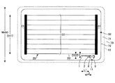
図7は、本発明の第5の実施形態である車両用アンテナが設置されたリヤガラスの全体平面図である。
<Fifth Embodiment>
FIG. 7 is an overall plan view of a rear glass on which a vehicle antenna according to a fifth embodiment of the present invention is installed.
本実施形態において、図3のガラスアンテナ10と比較して、本実施形態において、ガラスアンテナ11は、給電点8から延在する第1のアンテナエレメント1に加えて、第2のアンテナエレメント2が設けられている。
In this embodiment, compared with the
本実施形態において、アンテナエレメント2は、給電点8において、アンテナエレメント1とは異なる接続点を起点に、略水平方向に、換言すればアンテナエレメント1と平行に延在されていればよい。さらにアンテナエレメント2は、アンテナエレメント1と同じ方向に延在されている。
In the present embodiment, the
ここで、アンテナエレメント2は、アンテナエレメント1とは非接触であって、アンテナエレメント2とは異なる周波数帯の垂直偏波を受信する。詳しくは、アンテナエレメント1がバンドIIIの帯域の放送波を受信し、アンテナエレメント2がLバンドの帯域の放送波を受信する。
Here, the
アンテナエレメント2は、デジタルオーディオ放送におけるLバンド用のアンテナ素子である。LバンドはバンドIIIよりも周波数が高いため、第2のアンテナエレメント2の導体長は、第1のアンテナエレメント1の導体長よりも顕著に短く形成されている。
The
ここで、帯域幅が広く垂直偏波のDABの周波数帯のうち、第2の周波数帯として、Lバンドにおける中心周波数での空気中の波長をλ02とし、前記窓ガラスの波長短縮率をkとし、前記窓ガラス上での波長をλg2=λ02・kとする。このとき、第2のアンテナエレメント2の導体長は、(1/8)・λg2以上(3/8)・λg2以下であれば、第2の周波数帯のアンテナ利得向上の点で好ましい結果が得られる。詳細は実施例4で説明する。
なお、λg1とλg2とを総称してλgとする。
Here, the wavelength in the air at the center frequency in the L band is λ 02 as the second frequency band out of the DAB frequency band having a wide bandwidth and vertical polarization, and the wavelength reduction rate of the window glass is k. And the wavelength on the window glass is λ g2 = λ 02 · k. At this time, if the conductor length of the
Note that λ g1 and λ g2 are collectively referred to as λ g .
例えば、Lバンド(1452〜1492MHz)の中心周波数は1472MHzである。したがって、Lバンドのアンテナ利得を向上させたい場合、電波の速さを3.0×10⁸m/sとし、波長短縮率kを0.64とすると、アンテナエレメント2の(最長)経路長を、16mm以上48mm以下に調整するとよい。
For example, the center frequency of the L band (1452-1492 MHz) is 1472 MHz. Therefore, if it is desired to improve the L-band antenna gain, assuming that the speed of the radio wave is 3.0 × 10 8 m / s and the wavelength shortening rate k is 0.64, the (longest) path length of the
すなわち、ガラスアンテナ11の形状によれば、アンテナエレメント2の導体長は第2の放送周波数帯(Lバンド)で共振する長さに基づいて設定されている。
That is, according to the shape of the
なお、本実施形態では、アンテナエレメント2(第2のアンテナ導体の一例)は、Lバンドの性能向上のために設置されるが、第1の実施形態のようにアンテナエレメント2がない場合でもLバンドの性能が十分得られることもある。
In the present embodiment, the antenna element 2 (an example of the second antenna conductor) is installed for improving the performance of the L band. However, even if the
ここで、車両は移動体であるため、複数のアンテナを設け、場所によって受信感度の良い何れか一方のアンテナに切り替え可能な電波選択能(ダイバーシティ)を備えると好ましい。 Here, since the vehicle is a moving body, it is preferable to provide a plurality of antennas and to have a radio wave selection ability (diversity) that can be switched to one of the antennas having good reception sensitivity depending on the location.
そのため、本発明において、窓ガラス60の幅方向の中心線12で概略線対称に本発明のアンテナ10と同様構成のアンテナを設けることもできる。この際、複数のアンテナは互いに干渉を避けるため、所定距離(例えば、207MHzの0.2波長である186mm以上)離れて設置すると好ましい。このように、窓ガラス60に複数のガラスアンテナを設置して、アンテナ切り替えにより受信性能を向上させる効果を得られる。
Therefore, in the present invention, an antenna having the same configuration as that of the
また、放送波(テレビ、AM、FM等)を受信するための別の用途のガラスアンテナをリヤガラスに設けてもよい。 Further, a glass antenna for another use for receiving broadcast waves (television, AM, FM, etc.) may be provided on the rear glass.
上述のように、リヤガラスにおいて、本発明のガラスアンテナを2つ以上設ける場合、又は本アンテナと別のガラスアンテナを設ける場合、2つのガラスアンテナは窓ガラスにおいて、対角線を除く辺(図3の場合は、もう一つのガラスアンテナは下辺左下又は上辺右上、図4の場合、もう一つのガラスアンテナは下辺左下又は上辺右上)に設置されると好ましい。 As described above, when two or more glass antennas of the present invention are provided on the rear glass, or when a glass antenna different from the present antenna is provided, the two glass antennas are on the side of the window glass except for diagonal lines (in the case of FIG. 3). The other glass antenna is preferably installed at the lower left corner or upper right corner, and in the case of FIG. 4, the other glass antenna is installed at the lower left corner or upper upper corner).
また、本発明のガラスアンテナと、別の部位(例えば、フロントガラスやシャークフィン、スポイラー)に設けられるアンテナを切り替え可能にしてもよい。 Moreover, you may enable it to switch the antenna provided in another site | part (for example, a windshield, a shark fin, a spoiler) and the glass antenna of this invention.
以上、ガラスアンテナ及び窓ガラスを複数の実施形態例により説明したが、本発明は上記実施形態例に限定されるものではない。他の実施形態例の一部又は全部との組み合わせや置換などの種々の変形及び改良が、本発明の範囲内で可能である。 As mentioned above, although the glass antenna and the window glass were demonstrated by the some example of embodiment, this invention is not limited to the said example of embodiment. Various modifications and improvements, such as combinations and substitutions with part or all of other example embodiments, are possible within the scope of the present invention.
上述したガラスアンテナの形態を実際の自動車用窓ガラス(リヤガラス)に取り付けて作製された自動車用ガラスアンテナについて、そのアンテナ利得の実測結果について説明する。 An actual measurement result of the antenna gain of an automotive glass antenna manufactured by attaching the above-described glass antenna to an actual automotive window glass (rear glass) will be described.
アンテナ利得は、ガラスアンテナが形成された自動車用窓ガラスを、ターンテーブル上の自動車の窓枠に水平面に対して下記の所定の角度をつけた状態で組みつけて実測された。水平方向から窓ガラスに対して全方向から電波が照射されるように、ターンテーブルを回転させた。 The antenna gain was measured by assembling an automobile window glass on which a glass antenna was formed, with the following predetermined angle with respect to a horizontal plane on an automobile window frame on a turntable. The turntable was rotated so that radio waves were applied from all directions to the window glass from the horizontal direction.
給電点は、アンプ及び測定ケーブルを介してネットワークアナライザーとなり、各接続点はコネクタで結線されている。 The feeding point becomes a network analyzer through an amplifier and a measurement cable, and each connection point is connected by a connector.
アンテナのガラスを組みつけた自動車中心をターンテーブルの回転軸に合わせて、自動車を水平方向に360°回転させて行った。アンテナ利得のデータは、回転角度3°毎に、バンドIIIの周波数範囲(174〜240Mz)において3MHz毎に測定された。電波の発信位置とアンテナ導体との仰角は略水平方向(地面と平行な面を仰角=0°、天頂方向を仰角=90°とする場合、仰角=0°の方向)で測定した。アンテナ利得は、半波長ダイポールアンテナを基準とし、半波長ダイポールアンテナのアンテナ利得が0dBdとなるように標準化した。 The vehicle center with the antenna glass assembled was aligned with the rotation axis of the turntable, and the vehicle was rotated 360 ° horizontally. The antenna gain data was measured every 3 MHz in the frequency range of band III (174 to 240 Mz) at every rotation angle of 3 °. The elevation angle between the transmission position of the radio wave and the antenna conductor was measured in a substantially horizontal direction (when the plane parallel to the ground is elevation angle = 0 ° and the zenith direction is elevation angle = 90 °, the elevation angle = 0 ° direction). The antenna gain was standardized so that the antenna gain of the half-wave dipole antenna was 0 dBd with the half-wave dipole antenna as a reference.
((実施例1))
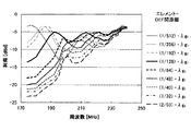
図8Aは、図3に示す車両用アンテナのアンテナエレメントの長さを変化させたときの、バンドIIIでの各周波数におけるアンテナ利得を示すグラフである。
((Example 1))
FIG. 8A is a graph showing the antenna gain at each frequency in band III when the length of the antenna element of the vehicle antenna shown in FIG. 3 is changed.
図8A及び図8B、及び表1は、図3に示すガラスアンテナ10の形態を実際の自動車のリヤガラスに取り付けたことにより作製された自動車用ガラスアンテナの実測データである。図8Aは、エレメント−デフォッガ間距離D1は(1/192)・λg1と固定したまま、アンテナエレメント1の導体長L1[mm]を(1/32)・λg1、(1/16)・λg1、(1/12)・λg1、(1/10)・λg1、(1/8)・λg1、(1/6)・λg1、(1/5)・λg1、(1/4)・λg1に変化させたときのバンドIII(174〜240MHz)における平均利得であり、横軸が周波数[MHz]、縦軸が平均利得[dBd]である。平均利得は、前記帯域内において回転角度3°毎のアンテナ利得の帯域での平均値を示している。
8A and 8B and Table 1 are actual measurement data of a glass antenna for an automobile manufactured by attaching the form of the
本発明は水平成分が長い水平パターン(横パターン)であって、図3の実施形態の形状において窓ガラス等の寸法は、単位をmmとして
ガラス垂直高さWv60:273
ガラス縦Wh60:380
開口部Oh:330
デフォッガ縦長Dh17:260
各エレメントの導体幅は、0.8mmである。給電点8及び9は、縦が11mm、横が12mmの長方形である。給電点8、9は、16mm離間しているとする。
The present invention is a horizontal pattern having a long horizontal component (horizontal pattern). In the shape of the embodiment of FIG. 3, the size of the window glass or the like is a glass vertical height Wv60: 273, where the unit is mm.
Glass length Wh60: 380
Opening Oh: 330
Defogga Vertical Dh17: 260
The conductor width of each element is 0.8 mm. The feeding points 8 and 9 are rectangles having a length of 11 mm and a width of 12 mm. It is assumed that the feeding points 8 and 9 are separated by 16 mm.
ここで、表1に図8Aで示すグラフにおける各導体長L1の利得のバンドIII全域の平均値を示す。 Here, Table 1 shows an average value of the entire band III of the gain of each conductor length L1 in the graph shown in FIG. 8A.
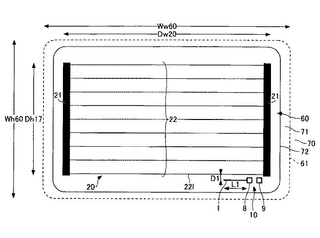
図8Bは、アンテナエレメントの導体長L1とバンドIIIにおける平均利得の相関関係を示すプロットである。図8Bのプロットにおいて、導体長L1を変化させたときの平均利得の変化量に対して、近似曲線を引くと、(1/8)・λg1の点で傾きが変化していることがわかる。これにより、少なくとも(1/8)・λg1以下では、アンテナエレメント1の導体長L1は、導体長が短くなることにともない、平均利得の向上率が高い。
FIG. 8B is a plot showing the correlation between the conductor length L1 of the antenna element and the average gain in band III. In the plot of FIG. 8B, when an approximate curve is drawn with respect to the amount of change in average gain when the conductor length L1 is changed, it can be seen that the slope changes at a point of (1/8) · λg1. . Thus, at least (1/8) · λ g1 or less, the conductor length L1 of the
図8A、図8B、表1は実測データのため、誤差を考慮して、アンテナエレメント1の導体長L1は(1/6)・λg1以下であると好ましい。また、図8Bで示すように(1/8)・λg1以下であるとさらに好ましい。
8A and 8B and Table 1 are actually measured data. Therefore, the conductor length L1 of the
((実施例2))
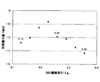
図9Aは、図3に示す車両用アンテナのアンテナエレメント1とデフォッガ(DEF)20に最近接するヒーター線22lとの距離を変化させたときの、バンドIIIでの各周波数におけるアンテナ利得を示すグラフである。
((Example 2))
9A is a graph showing the antenna gain at each frequency in band III when the distance between the
図9A及び図9B、及び表2は、図3に示すガラスアンテナ10の形態を実際の自動車のリヤガラスに取り付けたことにより作製された自動車用ガラスアンテナの実測データである。図9Aは、導体長L1を(1/32)・λg1と固定したまま、アンテナエレメント1とデフォッガの最近接のヒーター線22lとの距離[mm]を、(1/512)・λg1、(1/256)・λg1、(1/192)・λg1、(1/128)・λg1、(1/64)・λg1、(1/48)・λg1、(1/40)・λg1、(1/32)・λg1、(2/53)・λg1に変化させたときのバンドIII(174〜240MHz)における平均利得である。図9Aは、横軸が周波数[MHz]、縦軸が平均利得[dBd]である。平均利得は、前記帯域内において回転角度3°毎のアンテナ利得の帯域での平均値を示している。
9A and 9B and Table 2 are actual measurement data of a glass antenna for an automobile manufactured by attaching the form of the
本実施例において、ガラスアンテナ10以外の寸法は、実施例1と同様である。
In the present embodiment, dimensions other than the
ここで、表2に図9Aで示すグラフにおけるアンテナエレメント−デフォッガ(アンテナエレメント1とアンテナエレメント最近接のヒーター線22l)間距離D1の利得のバンドIII全域の平均値を示す。
Here, Table 2 shows the average value of the entire band III of the gain of the distance D1 between the antenna element and the defogger (the
図9Bは、アンテナエレメントとデフォッガとの距離D1とバンドIIIにおける利得の最小値の相関関係を示すプロットである。 FIG. 9B is a plot showing a correlation between the distance D1 between the antenna element and the defogger and the minimum gain value in band III.
図9Bのプロットにおいて、アンテナエレメント1とヒーター線22lとの最近接距離D1を変化させたときの平均利得の変化量に対して、近似曲線を引くと、(1/48)・λg1の点で傾きが変化していることがわかる。これにより、少なくとも(1/48)・λg1より大きいと、アンテナエレメント1とデフォッガの最近接のヒーター線22lとの距離の離間に伴う、平均利得の低下率が高い。
In the plot of FIG. 9B, when an approximate curve is drawn with respect to the change amount of the average gain when the closest distance D1 between the
図9A、図9B、表2は実測データのため、誤差を考慮して、アンテナエレメント1とデフォッガ20の最近接のヒーター線22lとの距離D1は(1/40)・λg1以下であると好ましい。また、図9Bで示すように(1/48)・λg1以下であるとさらに好ましい。
9A and 9B and Table 2 are actually measured data, and in consideration of errors, the distance D1 between the
((実施例3))
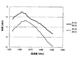
図10Aは、図4に示す車両用アンテナにおいて、デフォッガ20におけるヒーター縦線23の長さを変化させたときの、バンドIIIでの各周波数におけるアンテナ利得を示すグラフである。
((Example 3))
10A is a graph showing the antenna gain at each frequency in band III when the length of the heater
図10A及び図10B、及び表3は、図7に示すガラスアンテナ10Cの形態を実際の自動車のリヤガラスに取り付けたことにより作製された自動車用ガラスアンテナの実測データである。図10Aは、導体長L1を(1/32)・λg1に固定し、且つアンテナエレメント1とデフォッガの最近接のヒーター線22lとの距離D1[mm]を(1/192)・λg1と固定した状態で、ヒーター縦線23の長さを、0.13・λg1、0.16・λg1、0.19・λg1、0.26・λg1、0.29・λg1、0.32・λg1、0.36・λg1に変化させたときのバンドIII(174〜240MHz)における平均利得である。図10Aは、横軸が周波数[MHz]、縦軸が平均利得[dBd]である。平均利得は、前記帯域内において回転角度3°毎のアンテナ利得の帯域での平均値を示している。
FIGS. 10A and 10B and Table 3 are actual measurement data of a glass antenna for an automobile produced by attaching the form of the glass antenna 10C shown in FIG. 7 to the rear glass of an actual automobile. In FIG. 10A, the conductor length L1 is fixed to (1/32) · λ g1 and the distance D1 [mm] between the
本発明は水平成分が長い水平パターン(横パターン)であって、図7の実施形態の形状において窓ガラス等の寸法は、単位をmmとして
ガラス垂直高さ:281
ガラス縦Wh60:490
開口部Oh:440
デフォッガ縦長Dh17:360
窓の接地角度は、35°である。その他、アンテナ構成は、導体長L1を(1/32)・λg1、アンテナエレメント−デフォッガ間距離D1は(1/192)・λg1と固定しており、給電点の構成は、第1実施例と同様である。
The present invention is a horizontal pattern having a long horizontal component (horizontal pattern). In the shape of the embodiment of FIG.
Glass length Wh60: 490
Opening section Oh: 440
Defogga Vertical Dh17: 360
The contact angle of the window is 35 °. In addition, in the antenna configuration, the conductor length L1 is fixed to (1/32) · λ g1 and the antenna element-defogger distance D1 is fixed to (1/192) · λ g1. Similar to the example.
ここで、表3に図10Aで示すグラフにおける各ヒーター縦線23の長さL23の利得のバンドIII全域の平均値を示す。
Here, Table 3 shows an average value of the entire band III of the gain of the length L23 of each heater
図10Bは、デフォッガ20のヒーター縦線23の長さL23とバンドIIIにおける利得の最小値の相関関係を示すプロットである。
FIG. 10B is a plot showing the correlation between the length L23 of the heater
図10Bのプロットにおいて、ヒーター縦線23の長さL23を変化させたときの平均利得の変化量に対して、近似曲線を引くと、(1/4)・λg1周辺の0.19・λg1、0.23・λg1、0.26・λg1の点で傾きが変化していることがわかる。これにより、少なくとも(1/4)・λg1周辺であると、デフォッガ20のヒーター縦線23を配置したことによって、平均利得は向上する。
In the plot of FIG. 10B, when an approximate curve is drawn with respect to the change amount of the average gain when the length L23 of the heater
図10A、図10B、表3は実測データのため、誤差を考慮して、DEFのヒーター縦線23の長さL23はλ/4±50%程度であると好ましい。また、図8Bで示すように0.16λg1〜0.30λg1であるとさらに好ましい。
10A and 10B and Table 3 are actually measured data, and in consideration of errors, the length L23 of the DEF heater
((実施例4))
図11Aは、図7に示す車両用アンテナについて、内側、外側の2本のエレメントの長さを変化させたときの、バンドIIIでの各周波数のアンテナ利得を示すグラフである。図11Bは、図7に示す車両用アンテナについて、内側、外側の2本のエレメントの長さを変化させたときの、Lバンドでの各周波数のアンテナ利得を示すグラフである。ここで、内側とはヒーター線に近接しているアンテナエレメントであり、外側とは当該アンテナエレメントよりもヒーター線から離れているアンテナエレメントである。
((Example 4))
FIG. 11A is a graph showing the antenna gain of each frequency in band III when the lengths of the inner and outer two elements are changed for the vehicle antenna shown in FIG. FIG. 11B is a graph showing the antenna gain of each frequency in the L band when the lengths of the inner and outer two elements are changed for the vehicle antenna shown in FIG. 7. Here, the inner side is an antenna element close to the heater wire, and the outer side is an antenna element farther from the heater wire than the antenna element.
本実施例において、アンテナ利得のデータは、回転角度3°毎に、バンドIIIの周波数範囲(174〜240Mz)において3MHz毎に、またLバンドの周波数範囲(1452〜1492MHz)において1.8MHz毎に測定された。 In this embodiment, the antenna gain data is obtained at every rotation angle of 3 °, every 3 MHz in the band III frequency range (174 to 240 Mz), and every 1.8 MHz in the L band frequency range (1452 to 1492 MHz). Measured.
本実施例において、ガラスアンテナ11において、アンテナエレメント2以外の寸法は、実施例3と同様である。
In this embodiment, the dimensions of the
外側が長い場合(外:50mm、内:20mm)と内側が長い場合(外:50mm、内:20mm)を比較した。図11Aより、DEFに近い方のエレメントが利得向上の効果が大きい。 The case where the outside was long (outside: 50 mm, inside: 20 mm) and the case where the inside was long (outside: 50 mm, inside: 20 mm) were compared. From FIG. 11A, the element closer to DEF has a large effect of gain improvement.
図7を参照して、第2のアンテナエレメント2を設ける場合は、第1のアンテナエレメント1よりも短く、第1のアンテナエレメント1及び第2のアンテナエレメント2は、最近接のヒーター線22lと略平行に設けられる。
Referring to FIG. 7, when the
よってヒーター線22lと近接して設けられている方のアンテナエレメントがヒーター線22lと強く容量結合することができるため、デフォッガと容量結合することによる垂直偏波を受信感度が向上しやすくなる。 Therefore, since the antenna element provided closer to the heater wire 22l can be strongly capacitively coupled to the heater wire 22l, it is easy to improve the reception sensitivity of vertical polarization due to capacitive coupling with the defogger.
例えば、図11A及び図11Bにおいて、実線は、外側(図7で下側)が第1のアンテナエレメント1、内側(図7で上側)が第2のアンテナエレメント2である場合の利得を示し、点線は、外側が第2のアンテナエレメント2、内側が第1のアンテナエレメント1である場合の利得を示す。
For example, in FIGS. 11A and 11B, the solid line indicates the gain when the outer side (lower side in FIG. 7) is the
ここで、表4に図11A及び図11Bで示すグラフにおける利得のバンドIII全域及びLバンド全域の平均値を示す。 Here, Table 4 shows average values of gains in the entire band III and the entire L band in the graphs shown in FIGS. 11A and 11B.
図11Aに示すように、バンドIIIでは、導体長の長い第1のアンテナエレメント1を内側に設置すると、利得が向上する。また、図11Bに示すように、Lバンドでは、導体長の長い第1のアンテナエレメント1を外側に設置すると、利得が向上する。
As shown in FIG. 11A, in band III, when the
ここで、表4に図11Aで示すグラフにおける各ヒーター縦線23の長さL23の利得のバンドIII全域の平均値を示す。
Here, Table 4 shows the average value of the entire band III of the gain of the length L23 of each heater
例えば図11Aで示すバンドIIIにおいて、利得の最小値は、189MHzのとき、外が第1のアンテナエレメントの場合は−11.1dB、内側が第1のアンテナエレメントの場合は、−10.3dBとなる。 For example, in the band III shown in FIG. 11A, the minimum value of the gain is 189 MHz, −11.1 dB when the outside is the first antenna element, and −10.3 dB when the inside is the first antenna element. Become.
また図11Bで示すLバンドにおいて、利得の最小値は、1491MHzのとき外側が第1のアンテナエレメントの場合は、−5.4dB、内側が第1のアンテナエレメントの場合は、−7.8dBである。そのため、最小値の所望値(−12dB)に対してより余裕がなかったバンドIIIで利得が向上する方が好ましい。 Further, in the L band shown in FIG. 11B, the minimum value of the gain is −5.4 dB when the outside is the first antenna element at 1491 MHz, and −7.8 dB when the inside is the first antenna element. is there. For this reason, it is preferable that the gain is improved in band III where there is no margin with respect to the minimum desired value (−12 dB).
よって、アンテエレメントを2つ設ける場合は、バンドIIIに対応するための、導体長の長いアンテナエレメント1をデフォッガ20の最外のヒーター線22l(22u)により近接して設置すると、ガラスアンテナとしてより好適になる。この場合、第1のアンテナエレメント1は、第2のアンテナエレメント2の全て及びヒーター線22lに挟まれるように配置されている。
Therefore, when two antenna elements are provided, if the
なお、Lバンドの受信性能を重視する場合は、第2のアンテナエレメント2がヒーター線22lに近接している逆の配置でもあってもよい。
When importance is attached to the reception performance of the L band, the reverse arrangement may be employed in which the
1 第1のアンテナエレメント
2 第2のアンテナエレメント
8 給電点(芯線側給電点)
9 接地側給電点
10,10A,10B,11 ガラスアンテナ
20 デフォッガ
21 バスバー
22 ヒーター線
22l,22u 第1のヒーター線
23 ヒーター縦線
60 窓ガラス(後部窓ガラス)
70,70B バックドア、車体ボディ
72 開口部
72B 第2の開口部
73 樹脂パネル
74 第1の開口部
DESCRIPTION OF
9 Ground-side feeding points 10, 10A, 10B, 11 Glass antenna
20
70, 70B Back door,
Claims (12)
前記デフォッガは、前記後部窓ガラスの下部側から上部側まで水平方向に沿って延在する複数のヒーター線と、前記後部窓ガラスの左右両端部側において上下方向に延在し、前記複数のヒーター線に給電する複数のバスバーとを有し、
前記車両用ガラスアンテナは、前記後部窓ガラスの少なくとも左右何れか一方の端部側で、前記デフォッガよりも上部又は下部に設けられ、
前記車両用ガラスアンテナは、
給電点と、
前記給電点から略水平方向に延在する第1のアンテナエレメントと、を備えており、
受信する周波数帯域の中心周波数における空気中の波長をλ、ガラス波長短縮率をk、前記後部窓ガラス上での波長をλg=λ・k、としたとき、
前記第1のアンテナエレメントの導体長が(1/6)・λg以下であり、
前記第1のアンテナエレメントと、前記ヒーター線のうち最外に設けられ、前記第1のアンテナエレメントと最近接する第1のヒーター線との距離が(1/40)・λg以下である、ことを特徴とする車両用ガラスアンテナ。 In a glass antenna for a vehicle that is provided with an electrically heated defogger on the rear window glass of the vehicle and receives vertical polarization of DAB,
The defogger includes a plurality of heater wires extending in a horizontal direction from a lower side to an upper side of the rear window glass, and extending in a vertical direction on both right and left end sides of the rear window glass. A plurality of bus bars for supplying power to the wire,
The vehicle glass antenna is provided on the upper or lower side of the defogger on at least one of the left and right ends of the rear window glass.
The vehicle glass antenna is
A feeding point;
A first antenna element extending in a substantially horizontal direction from the feeding point,
When the wavelength in the air at the center frequency of the frequency band to be received is λ, the glass wavelength shortening rate is k, and the wavelength on the rear window glass is λ g = λ · k,
The conductor length of the first antenna element is (1/6) · λ g or less,
The distance between the first antenna element and the first heater line provided on the outermost side of the heater wire and closest to the first antenna element is (1/40) · λ g or less. A glass antenna for a vehicle.
請求項1記載の車両用ガラスアンテナ。 The conductor length of the first antenna element is (1/8) · λg or less,
The glass antenna for a vehicle according to claim 1.
当該車両用ガラスアンテナは、前記DABのバンドIIIの垂直偏波を受信する、
請求項1又は2記載の車両用ガラスアンテナ。 The first antenna element and the first heater wire are capacitively coupled,
The vehicular glass antenna receives vertically polarized waves of the band III of the DAB.
The glass antenna for vehicles according to claim 1 or 2.
請求項1から3のいずれか一項に記載の車両用ガラスアンテナ。 The feed point includes a core wire side feed point and a ground side feed point arranged in parallel with the core wire side feed point.
The glass antenna for vehicles as described in any one of Claim 1 to 3.
請求項1から4のいずれか一項に記載の車両用ガラスアンテナ。 The first antenna element extends from the feeding point toward a center line in the vehicle width direction of the rear window glass.
The glass antenna for vehicles as described in any one of Claim 1 to 4.
請求項1から5のいずれか一項に記載の車両用ガラスアンテナ。 A second antenna element extending from the feed point and receiving vertically polarized waves in a frequency band different from that of the first antenna element;
The glass antenna for vehicles as described in any one of Claim 1 to 5.
前記第1のアンテナエレメント及び前記第2のアンテナエレメントは、前記第1のヒーター線と略平行に延在して、垂直方向に並んで延在しており、
前記第1のアンテナエレメントは、前記第2のアンテナエレメントよりも前記ヒーター線に近接して設けられている、
請求項6記載の車両用ガラスアンテナ。 The second antenna element is shorter than the first antenna element;
The first antenna element and the second antenna element extend substantially parallel to the first heater wire and extend side by side in the vertical direction,
The first antenna element is provided closer to the heater wire than the second antenna element.
The glass antenna for vehicles according to claim 6.
前記周波数帯域の中心周波数における空気中の波長をλ、ガラス波長短縮率をk、λg=λ・k、としたとき、前記ヒーター縦線の長さが(1/8)・λg以上(3/8)・λg以下である、
請求項1から7のいずれか一項記載の車両用ガラスアンテナ。 The defogger has a heater vertical line that intersects the plurality of heater lines in the vertical direction,
When the wavelength in the air at the center frequency of the frequency band is λ, the glass wavelength shortening rate is k, and λ g = λ · k, the length of the heater vertical line is equal to or greater than (1/8) · λ g ( 3/8) · λ g or less,
The glass antenna for vehicles as described in any one of Claim 1 to 7.
請求項1から8のいずれか一項記載の車両用ガラスアンテナ。 The vehicle is a hatchback type;
The glass antenna for vehicles according to any one of claims 1 to 8.
前記後部窓ガラスは、前記開口部を覆うように前記バックドアに取り付けられ、
前記第1のヒーター線と該第1のヒーター線に対向する前記開口部の下縁部又は上縁部との距離が、前記第1のアンテナエレメントの長さよりも短い、
請求項9項に記載の車両用ガラスアンテナ。 In the rear part of the vehicle, an opening for visually confirming the rear is formed, and a back door is attached so as to be opened and closed.
The rear window glass is attached to the back door so as to cover the opening,
A distance between the first heater line and a lower edge or an upper edge of the opening facing the first heater line is shorter than a length of the first antenna element;
The vehicle glass antenna according to claim 9.
前記バックドアには、前記第1の開口部を覆うように樹脂製のパネルが取り付けられ、
前記樹脂製のパネルは、前記第1の開口部よりも小さく、後方を視認するための第2の開口部が形成され、
前記後部窓ガラスは、前記第2の開口部を覆うように前記バックドアに取り付けられ、
前記第1のヒーター線と該第1のヒーター線に対向する前記第2の開口部の下縁部又は上縁部との距離が、前記第1のアンテナエレメントの長さよりも短い、
請求項9項に記載の車両用ガラスアンテナ。 At the rear of the vehicle, a first opening is formed, and a back door is attached to be openable and closable.
A resin panel is attached to the back door so as to cover the first opening,
The resin panel is smaller than the first opening, and a second opening for visually recognizing the rear is formed.
The rear window glass is attached to the back door so as to cover the second opening,
A distance between the first heater line and a lower edge or an upper edge of the second opening facing the first heater line is shorter than a length of the first antenna element;
The vehicle glass antenna according to claim 9.
Priority Applications (4)
| Application Number | Priority Date | Filing Date | Title |
|---|---|---|---|
| JP2015114724A JP2017005354A (en) | 2015-06-05 | 2015-06-05 | Glass antenna for vehicle and rear window glass with antenna for vehicle |
| EP16001158.1A EP3101728B1 (en) | 2015-06-05 | 2016-05-20 | Glass antenna for vehicle and rear window glass with glass antenna for vehicle |
| US15/163,460 US20160359219A1 (en) | 2015-06-05 | 2016-05-24 | Glass antenna for vehicle and rear window glass with glass antenna for vehicle |
| CN201610389063.XA CN106252819B (en) | 2015-06-05 | 2016-06-02 | Glass antenna for vehicle and rear window glass having the same |
Applications Claiming Priority (1)
| Application Number | Priority Date | Filing Date | Title |
|---|---|---|---|
| JP2015114724A JP2017005354A (en) | 2015-06-05 | 2015-06-05 | Glass antenna for vehicle and rear window glass with antenna for vehicle |
Publications (1)
| Publication Number | Publication Date |
|---|---|
| JP2017005354A true JP2017005354A (en) | 2017-01-05 |
Family
ID=56068599
Family Applications (1)
| Application Number | Title | Priority Date | Filing Date |
|---|---|---|---|
| JP2015114724A Withdrawn JP2017005354A (en) | 2015-06-05 | 2015-06-05 | Glass antenna for vehicle and rear window glass with antenna for vehicle |
Country Status (4)
| Country | Link |
|---|---|
| US (1) | US20160359219A1 (en) |
| EP (1) | EP3101728B1 (en) |
| JP (1) | JP2017005354A (en) |
| CN (1) | CN106252819B (en) |
Cited By (5)
| Publication number | Priority date | Publication date | Assignee | Title |
|---|---|---|---|---|
| JP2019009668A (en) * | 2017-06-27 | 2019-01-17 | Agc株式会社 | Glass antenna and vehicle window glass |
| WO2019049783A1 (en) * | 2017-09-05 | 2019-03-14 | 日本板硝子株式会社 | Rear glass and backdoor having rear glass |
| KR20200069939A (en) * | 2018-12-07 | 2020-06-17 | 현대자동차주식회사 | Vehicle and maehod of controlling the same |
| CN112219317A (en) * | 2018-06-05 | 2021-01-12 | Agc株式会社 | Vehicle window glass with terminal |
| WO2023204158A1 (en) * | 2022-04-19 | 2023-10-26 | Agc株式会社 | For-vehicle antenna device |
Families Citing this family (6)
| Publication number | Priority date | Publication date | Assignee | Title |
|---|---|---|---|---|
| EP3059801B1 (en) * | 2013-10-16 | 2019-04-24 | AGC Inc. | Electricity-supplying structure, resin plate for window provided with said structure, and method for manufacturing resin plate for window provided with electricity-supplying structure |
| JP6879744B2 (en) * | 2017-01-11 | 2021-06-02 | 日本板硝子株式会社 | Vehicle window glass |
| JP6868396B2 (en) * | 2017-01-11 | 2021-05-12 | 日本板硝子株式会社 | Window glass |
| JP7204736B2 (en) * | 2018-03-16 | 2023-01-16 | 日本板硝子株式会社 | rear glass |
| JP7283269B2 (en) | 2019-06-28 | 2023-05-30 | Agc株式会社 | Back door and rear glass |
| JP2023023135A (en) * | 2021-08-04 | 2023-02-16 | Agc株式会社 | Window glass for vehicle |
Citations (4)
| Publication number | Priority date | Publication date | Assignee | Title |
|---|---|---|---|---|
| JPH07212119A (en) * | 1994-01-26 | 1995-08-11 | Central Glass Co Ltd | Glass antenna for vehicle |
| JP2009105665A (en) * | 2007-10-23 | 2009-05-14 | Central Glass Co Ltd | Glass antenna for automobile |
| JP2010154504A (en) * | 2008-11-20 | 2010-07-08 | Asahi Glass Co Ltd | Glass antenna and window glass for vehicle |
| US20110043419A1 (en) * | 2008-09-16 | 2011-02-24 | Central Glass Company, Limited | Glass Antenna for Vehicle |
Family Cites Families (13)
| Publication number | Priority date | Publication date | Assignee | Title |
|---|---|---|---|---|
| US4803492A (en) * | 1985-11-25 | 1989-02-07 | Central Glass Company, Limited | Vehicle window glass antenna |
| US5952977A (en) * | 1994-11-04 | 1999-09-14 | Mazda Motor Corporation | Glass antenna |
| US5923298A (en) * | 1997-04-30 | 1999-07-13 | Ford Motor Company | Multiband reception antenna for terrestrial digital audio broadcast bands |
| US6441791B1 (en) * | 2000-08-21 | 2002-08-27 | Nippon Sheet Glass Co., Ltd. | Glass antenna system for mobile communication |
| EP1356541A2 (en) * | 2001-01-04 | 2003-10-29 | Nippon Sheet Glass Co., Ltd. | Glass antenna and glass antenna system using the same |
| DE10356830A1 (en) * | 2003-12-05 | 2005-07-07 | Robert Bosch Gmbh | Vehicle window antenna |
| JP5299276B2 (en) * | 2007-06-22 | 2013-09-25 | 旭硝子株式会社 | High frequency glass antenna for automobile |
| US8130156B2 (en) * | 2009-03-05 | 2012-03-06 | Gm Global Technology Operations, Llc | Center high mount stop lamp assembly with integrated radio frequency antenna |
| JP5720308B2 (en) * | 2010-06-16 | 2015-05-20 | セントラル硝子株式会社 | Glass antenna for vehicles |
| JP5655522B2 (en) * | 2010-11-24 | 2015-01-21 | 旭硝子株式会社 | Vehicle antenna device |
| JP5742509B2 (en) * | 2011-06-27 | 2015-07-01 | セントラル硝子株式会社 | Glass antenna for vehicles |
| JP2013131889A (en) | 2011-12-21 | 2013-07-04 | Central Glass Co Ltd | Vehicular glass antenna |
| JP6221773B2 (en) * | 2014-01-27 | 2017-11-01 | セントラル硝子株式会社 | Glass antenna |
-
2015
- 2015-06-05 JP JP2015114724A patent/JP2017005354A/en not_active Withdrawn
-
2016
- 2016-05-20 EP EP16001158.1A patent/EP3101728B1/en active Active
- 2016-05-24 US US15/163,460 patent/US20160359219A1/en not_active Abandoned
- 2016-06-02 CN CN201610389063.XA patent/CN106252819B/en active Active
Patent Citations (4)
| Publication number | Priority date | Publication date | Assignee | Title |
|---|---|---|---|---|
| JPH07212119A (en) * | 1994-01-26 | 1995-08-11 | Central Glass Co Ltd | Glass antenna for vehicle |
| JP2009105665A (en) * | 2007-10-23 | 2009-05-14 | Central Glass Co Ltd | Glass antenna for automobile |
| US20110043419A1 (en) * | 2008-09-16 | 2011-02-24 | Central Glass Company, Limited | Glass Antenna for Vehicle |
| JP2010154504A (en) * | 2008-11-20 | 2010-07-08 | Asahi Glass Co Ltd | Glass antenna and window glass for vehicle |
Cited By (7)
| Publication number | Priority date | Publication date | Assignee | Title |
|---|---|---|---|---|
| JP2019009668A (en) * | 2017-06-27 | 2019-01-17 | Agc株式会社 | Glass antenna and vehicle window glass |
| WO2019049783A1 (en) * | 2017-09-05 | 2019-03-14 | 日本板硝子株式会社 | Rear glass and backdoor having rear glass |
| JP2019043453A (en) * | 2017-09-05 | 2019-03-22 | 日本板硝子株式会社 | Rear glass and back door having rear glass |
| CN112219317A (en) * | 2018-06-05 | 2021-01-12 | Agc株式会社 | Vehicle window glass with terminal |
| KR20200069939A (en) * | 2018-12-07 | 2020-06-17 | 현대자동차주식회사 | Vehicle and maehod of controlling the same |
| KR102646664B1 (en) | 2018-12-07 | 2024-03-13 | 현대자동차주식회사 | Vehicle and maehod of controlling the same |
| WO2023204158A1 (en) * | 2022-04-19 | 2023-10-26 | Agc株式会社 | For-vehicle antenna device |
Also Published As
| Publication number | Publication date |
|---|---|
| CN106252819A (en) | 2016-12-21 |
| CN106252819B (en) | 2020-06-05 |
| EP3101728B1 (en) | 2019-04-03 |
| EP3101728A1 (en) | 2016-12-07 |
| US20160359219A1 (en) | 2016-12-08 |
Similar Documents
| Publication | Publication Date | Title |
|---|---|---|
| JP2017005354A (en) | Glass antenna for vehicle and rear window glass with antenna for vehicle | |
| EP2323221B1 (en) | Glass antenna | |
| JP4803004B2 (en) | High frequency glass antenna for automobile and window glass plate | |
| JP4941171B2 (en) | Glass antenna for vehicles | |
| US10290932B2 (en) | Glass antenna and vehicle window glass provided with glass antenna | |
| JP5141500B2 (en) | Glass antenna for vehicle and window glass for vehicle | |
| JP2009246844A (en) | Vehicle high-frequency glass antenna and vehicle windowpane | |
| JP5942851B2 (en) | Glass antenna for vehicle and window glass for vehicle | |
| JP5141503B2 (en) | Glass antenna for vehicle and window glass for vehicle | |
| JP4946639B2 (en) | High frequency glass antenna for automobile | |
| JP2009033687A (en) | Glass antenna for vehicle | |
| WO2012011354A1 (en) | Vehicle antenna | |
| EP2355237B1 (en) | Glass antenna and vehicular window glass including the same | |
| JP5003627B2 (en) | Glass antenna for vehicle and window glass for vehicle | |
| JP2012044254A (en) | Vehicle antenna | |
| JP5387317B2 (en) | Glass antenna for vehicles | |
| EP2190058B1 (en) | Glass antenna and window glass for vehicle | |
| KR101340742B1 (en) | Glass antenna for vehicle | |
| JP5316230B2 (en) | Glass antenna | |
| JP4225373B2 (en) | Glass antenna for vehicles | |
| JP5633295B2 (en) | Vehicle antenna | |
| JP2010268358A (en) | On-vehicle glass antenna | |
| TW200939558A (en) | Vehicular reception equipment | |
| WO2012105456A1 (en) | Glass-integrated antenna and vehicle-use glazing provided with same | |
| JP5499810B2 (en) | Glass antenna for vehicle and window glass for vehicle |
Legal Events
| Date | Code | Title | Description |
|---|---|---|---|
| A621 | Written request for application examination |
Free format text: JAPANESE INTERMEDIATE CODE: A621 Effective date: 20180219 |
|
| A977 | Report on retrieval |
Free format text: JAPANESE INTERMEDIATE CODE: A971007 Effective date: 20190121 |
|
| A131 | Notification of reasons for refusal |
Free format text: JAPANESE INTERMEDIATE CODE: A131 Effective date: 20190129 |
|
| A761 | Written withdrawal of application |
Free format text: JAPANESE INTERMEDIATE CODE: A761 Effective date: 20190307 |