JP2017002988A - Shock absorber - Google Patents
Shock absorber Download PDFInfo
- Publication number
- JP2017002988A JP2017002988A JP2015117182A JP2015117182A JP2017002988A JP 2017002988 A JP2017002988 A JP 2017002988A JP 2015117182 A JP2015117182 A JP 2015117182A JP 2015117182 A JP2015117182 A JP 2015117182A JP 2017002988 A JP2017002988 A JP 2017002988A
- Authority
- JP
- Japan
- Prior art keywords
- side chamber
- valve
- pressure
- pressure side
- chamber
- Prior art date
- Legal status (The legal status is an assumption and is not a legal conclusion. Google has not performed a legal analysis and makes no representation as to the accuracy of the status listed.)
- Granted
Links
- 239000006096 absorbing agent Substances 0.000 title claims abstract description 52
- 230000035939 shock Effects 0.000 title claims abstract description 52
- 230000006835 compression Effects 0.000 claims abstract description 24
- 238000007906 compression Methods 0.000 claims abstract description 24
- 239000007788 liquid Substances 0.000 claims description 44
- 230000002093 peripheral effect Effects 0.000 claims description 18
- 238000000638 solvent extraction Methods 0.000 claims description 2
- 230000008602 contraction Effects 0.000 abstract description 16
- 230000004043 responsiveness Effects 0.000 abstract description 3
- 239000012530 fluid Substances 0.000 abstract 3
- 238000013016 damping Methods 0.000 description 35
- 230000004044 response Effects 0.000 description 5
- 239000010720 hydraulic oil Substances 0.000 description 4
- 238000009434 installation Methods 0.000 description 2
- 238000010030 laminating Methods 0.000 description 2
- 230000003746 surface roughness Effects 0.000 description 2
- 239000007864 aqueous solution Substances 0.000 description 1
- 230000009977 dual effect Effects 0.000 description 1
- 239000003921 oil Substances 0.000 description 1
- 238000005192 partition Methods 0.000 description 1
- 230000002265 prevention Effects 0.000 description 1
- 238000007788 roughening Methods 0.000 description 1
- XLYOFNOQVPJJNP-UHFFFAOYSA-N water Substances O XLYOFNOQVPJJNP-UHFFFAOYSA-N 0.000 description 1
Images


Abstract
Description
本発明は、緩衝器の改良に関する。 The present invention relates to an improved shock absorber.
従来、車両用の複筒型の緩衝器にあっては、シリンダと、シリンダ内に摺動自在に挿入されるピストンと、シリンダ内に移動自在に挿入されてピストンに連結されるピストンロッドと、シリンダ内にピストンで区画した伸側室と圧側室と、シリンダとこのシリンダの外周側に設けた外筒との間に設けた環状のリザーバと、シリンダの端部に嵌合されて圧側室とリザーバとを仕切るバルブケースと、ピストンに設けられて伸側室と圧側室とを連通する伸側ポートおよび圧側ポートと、ピストンの伸側室側に積層されて圧側ポートを開閉するチェックバルブと、ピストンの圧側室側に積層されて伸側ポートを開閉する伸側リーフバルブと、バルブケースに設けられて圧側室とリザーバを連通する排出ポートおよび吸込ポートと、バルブケースの圧側室側に積層されて吸込ポートを開閉するチェックバルブと、バルブケースのリザーバ側に積層されて排出ポートを開閉する圧側リーフバルブとを備えている(たとえば、特許文献1参照)。 Conventionally, in a double cylinder type shock absorber for a vehicle, a cylinder, a piston that is slidably inserted into the cylinder, a piston rod that is movably inserted into the cylinder and coupled to the piston, An extension side chamber and a pressure side chamber partitioned by a piston in the cylinder, an annular reservoir provided between the cylinder and an outer cylinder provided on the outer peripheral side of the cylinder, and a pressure side chamber and a reservoir fitted to the end of the cylinder A valve case for separating the pressure side, an expansion side port and a pressure side port provided on the piston for communicating the expansion side chamber and the pressure side chamber, a check valve stacked on the extension side chamber side of the piston to open and close the pressure side port, and a pressure side of the piston An extension side leaf valve that is stacked on the chamber side to open and close the extension side port, a discharge port and a suction port that are provided in the valve case and communicates with the pressure side chamber and the reservoir, and the pressure of the valve case A check valve for opening and closing the suction ports are stacked in the chamber side, and a pressure side leaf valve for opening and closing the exhaust port are stacked in the reservoir side of the valve case (e.g., see Patent Document 1).
そして、この緩衝器が収縮する収縮作動時では、ピストンロッドがシリンダ内に侵入して、シリンダ内で作動油が過剰となるため、過剰分の作動油がリザーバへ排出される。ここで、バルブケースには、吸込ポートを開閉するチェックバルブが着座する弁座に打刻オリフィスが設けてあって、緩衝器が低速で収縮する場合には、作動油は打刻オリフィスを通過して圧側室からリザーバへ排出される。 When the shock absorber is contracted, the piston rod enters the cylinder and the hydraulic oil becomes excessive in the cylinder, so that the excessive hydraulic oil is discharged to the reservoir. Here, the valve case is provided with a stamping orifice in the valve seat on which the check valve for opening and closing the suction port is seated, and when the shock absorber contracts at low speed, the hydraulic oil passes through the stamping orifice. The pressure side chamber is discharged to the reservoir.
したがって、このような複筒型の緩衝器にあっては、収縮する際のピストン速度が低速である場合には、オリフィス特有のピストン速度の二乗に比例する特性にて減衰力を発揮する。そして、ピストン速度が高速となると、圧側リーフバルブが撓んで排出ポートを連通させるため、緩衝器は、オリフィス特有の特性からピストン速度に比例するバルブ特性に切換わって減衰力を発揮する。 Therefore, in such a multi-cylinder shock absorber, when the piston speed when contracting is low, the damping force is exhibited with a characteristic proportional to the square of the piston speed peculiar to the orifice. When the piston speed becomes high, the compression side leaf valve bends and connects the discharge port, so that the shock absorber switches from the characteristic characteristic of the orifice to the valve characteristic proportional to the piston speed and exhibits a damping force.
このように前記した複筒型の緩衝器にあっては、低速で収縮する場合には、ピストン速度の二乗に比例するオリフィス特性で速やかに減衰力を立ち上げ得る。しかしながら、従来の緩衝器では、オリフィスを介してリザーバへ圧力が逃げるため、収縮時のピストン速度が低いとなかなか圧側室の圧力が上昇しないため、なお一層の圧側の減衰力の発生応答性の改善が望まれている。 Thus, in the above-described double cylinder type shock absorber, when contracting at a low speed, the damping force can be quickly started up with an orifice characteristic proportional to the square of the piston speed. However, in the conventional shock absorber, the pressure escapes to the reservoir through the orifice, so that the pressure in the compression side chamber does not rise easily when the piston speed at the time of contraction is low. Is desired.
そこで、本発明は、上記した不具合を改善するために創案されたものであって、その目的とするところは、圧側の減衰力の発生応答性を向上させる緩衝器の提供である。 Therefore, the present invention has been developed to improve the above-described problems, and an object of the present invention is to provide a shock absorber that improves the generation response of the compression side damping force.
上記した課題を解決するために、本発明の課題解決手段における緩衝器は、伸側室と圧側室とを連通するオリフィスを備える一方、バルブケースには、圧側室からリザーバへ向かう液体の流れのみを許容して液体の流れに抵抗を与える圧側減衰バルブとリザーバから圧側室へ向かう液体の流れのみを許容する逆止弁のみを設けている。このようにすると、収縮作動時においてピストン速度が低速域で圧側室からリザーバへ直接圧力が逃げないので、圧側室内の圧力が速やかに上昇する。 In order to solve the above-described problem, the shock absorber in the problem solving means of the present invention includes an orifice communicating the extension side chamber and the pressure side chamber, while the valve case only allows the flow of liquid from the pressure side chamber to the reservoir. Only a pressure side damping valve that allows resistance to the flow of liquid and a check valve that allows only the flow of liquid from the reservoir to the pressure side chamber are provided. In this way, the pressure does not escape directly from the pressure side chamber to the reservoir when the piston speed is low during the contraction operation, so that the pressure in the pressure side chamber rises quickly.
また、緩衝器が圧側室から伸側室へ向かう液体の流れのみを許容して液体の流れに抵抗を与える片効きの圧側オリフィスを備える場合には、圧側室内の圧力上昇が過剰となるのを阻止しつつ、伸縮の両側で独立した減衰力特性のチューニングが可能となる。 Also, if the shock absorber is equipped with a single-sided pressure-side orifice that allows only the flow of liquid from the pressure-side chamber to the extension-side chamber and provides resistance to the liquid flow, it prevents excessive pressure rise in the pressure-side chamber. However, it becomes possible to tune the damping force characteristics independently on both sides of the expansion and contraction.
さらに、ピストンに伸側室と圧側室とを連通するポートを設け、ピストンの伸側室側にポートを開閉するとともにポートに通じる圧側オリフィスを有する第一リーフバルブを積層し、第一リーフバルブの伸側室側に圧側オリフィスを開閉する第二リーフバルブを積層すると、簡単な構成で片効きの圧側オリフィスを構成できる。 In addition, the piston is provided with a port that communicates the extension side chamber and the pressure side chamber, and a first leaf valve having a pressure side orifice that opens and closes the port and is connected to the port is laminated on the extension side chamber side of the piston. If the second leaf valve for opening and closing the pressure side orifice is laminated on the side, a one-sided pressure side orifice can be configured with a simple configuration.
また、第二リーフバルブが内環と、圧側オリフィスを開閉する外環と、内環と外環とを接続する腕部とを備えて構成されると、腕部の幅および設置数の設定によって、圧側オリフィスを開放する開弁圧を容易にチューニング可能となる。 Further, when the second leaf valve is configured to include an inner ring, an outer ring that opens and closes the pressure side orifice, and an arm part that connects the inner ring and the outer ring, the width of the arm part and the number of installation are set. The valve opening pressure for opening the pressure side orifice can be easily tuned.
本発明の緩衝器によれば、圧側の減衰力の発生応答性を向上できる。 According to the shock absorber of the present invention, it is possible to improve the generation response of the compression side damping force.
以下、図に示した実施の形態に基づき、本発明を説明する。図1に示すように、一実施の形態における緩衝器Dは、シリンダ1と、当該シリンダ1内に摺動自在に挿入されるピストン2と、シリンダ1内に移動自在に挿入されてピストン2に連結されるピストンロッド3と、リザーバRとシリンダ1内の液室Lとを仕切るバルブケース4と、液室L内にピストン2で区画される伸側室R1と圧側室R2と、伸側室R1と圧側室R2とを連通するオリフィスOと、バルブケース4に設けた圧側減衰バルブ5および逆止弁6とを備えて構成されている。
The present invention will be described below based on the embodiments shown in the drawings. As shown in FIG. 1, a shock absorber D according to an embodiment includes a
また、本実施の形態における緩衝器Dの場合、リザーバRは、シリンダ1とシリンダ1の外周に設けた外筒7との間に形成されている。そして、シリンダ1内には、作動油等の液体が充填され、リザーバR内には液体と気体が充填されている。なお、液体は、作動油以外にも、たとえば、水、水溶液といった液体の使用もできる。
In the case of the shock absorber D in the present embodiment, the reservoir R is formed between the
以下、各部について詳細に説明する。シリンダ1内には、ピストンロッド3が移動自在に挿入され、このピストンロッド3の先端にピストン2が連結されている。具体的には、ピストンロッド3は、その図1中下端側に設けた小径部3aと、小径部3aの先端の外周に設けた螺子部3bとを備えている。また、ピストンロッド3の図1中上端側は、シリンダ1および外筒7の図1中上端に装着された環状のロッドガイド10内を通して外方へ突出されている。ロッドガイド10は、内周に筒状のブッシュ11を備えており、ブッシュ11内に挿通されるピストンロッド3を軸支して、当該ピストンロッド3の図1中上下方向である軸方向の移動を案内する。また、ロッドガイド10の図1中上方には、シリンダ1および外筒7とピストンロッド3との間をシールするシール部材12が積層されており、シリンダ1内が液密に保たれている。
Hereinafter, each part will be described in detail. A piston rod 3 is movably inserted into the
また、ロッドガイド10の図1中上端内周には、シール部材12のピストンロッド3の外周に摺接するシール部12aが収容される環状凹部10aが設けられている。この環状凹部10aは、ロッドガイド10に設けた戻り通路10bを通じてリザーバRへ通じ、ブッシュ11とピストンロッド3との間の摺動隙間を介して伸側室R1へ通じている。シール部材12の図1中下端には、ロッドガイド10の環状凹部10aに設けた段部10cに離着可能なチェックシール12bが設けられている。チェックシール12bは、段部10cに着座した状態では、環状凹部10aと戻り通路10bとの連通を遮断し、環状凹部10a内の圧力が高圧となると、撓んで段部10cから離座して環状凹部10aを戻り通路10bを介してリザーバRへ連通する。
1 is provided with an
シリンダ1内には、図2に示すように、ピストンロッド3に連結されたピストン2が摺動自在に挿入されている。このピストン2は、環状のディスク部2aと、ディスク部2aの外周に設けた筒部2bと、ディスク部2aに同一円周上に設けられて伸側室R1と圧側室R2とを連通する複数の伸側ポート2cと、同じくディスク部2aに同一円周上であって伸側ポート2cよりも外周側に設けられる複数の圧側ポート2dとを備えていて、シリンダ1内の液室Lを伸側室R1と圧側室R2とに区画している。
As shown in FIG. 2, a
また、ディスク部2aの図2中下端には、各伸側ポート2cの出口端に通じる環状窓2eと、環状窓2eと圧側ポート2dとの間から図中下方へ突出して伸側ポート2cを取り囲む環状の伸側弁座2fが設けられている。ピストン2の図2中上端には、各伸側ポート2cの入口端に通じる環状窓2gと、各圧側ポート2dの出口端に通じる環状窓2hと、環状窓2gと環状窓2hとの間から図中上方へ突出する環状の圧側内周弁座2iと、環状窓2hの外周から図中上方へ突出して圧側ポート2dの外周側を取り囲む環状の圧側外周弁座2jが設けられている。
Further, at the lower end in FIG. 2 of the
さらに、このピストン2の圧側室R2側である図2中下端には、伸側弁座2fに離着座して伸側ポート2cを開閉する伸側リーフバルブ8が積層されている。伸側リーフバルブ8は、複数枚の環状のリーフバルブを積層して構成されており、ピストン2とともにピストンロッド3の小径部3aの外周に組付けられ、螺子部3bに螺着されるピストンナット13によって当該小径部3aに装着される。伸側リーフバルブ8は、ピストンロッド3の小径部3aに装着されると内周が固定されて外周の撓みが許容される。また、伸側リーフバルブ8を構成するリーフバルブのうち伸側弁座2fに着座するリーフバルブには、切欠が設けられており、この切欠によってオリフィスOが形成されている。そして、緩衝器Dの伸長作動時において、伸側ポート2cを介して作用する伸側室R1の圧力が開弁圧に達するまでは、伸側リーフバルブ8が伸側弁座2fに着座状態に維持されるが、液体はオリフィスOを介して伸側室R1から圧側室R2へ移動できる。これに対して、緩衝器Dの伸長作動時において、伸側ポート2cを介して作用する伸側室R1の圧力が開弁圧に達すると、伸側リーフバルブ8が伸側弁座2fから離座して、伸側ポート2cを開く。また、緩衝器Dの収縮作動時には、伸側リーフバルブ8が圧側室R2の圧力で伸側弁座2fに押し付けられて着座状態となるが、液体はオリフィスOを介して圧側室R2から伸側室R1へ移動できる。つまり、このオリフィスOは、緩衝器Dの伸長作動時および収縮作動時の両方、つまり、伸圧両側で液体の通過を許容する両効きのオリフィスとされている。なお、オリフィスOは、伸側弁座2fに打刻して設ける凹部で形成されてもよい。また、ピストン2の構造は、一例であって、前記したところに限定されるものではなく、伸側ポート2cおよび圧側ポート2dの配置および形状も変更可能で、各弁座の形状も環状のほか花弁型の採用も可能である。伸側ポート2cの開閉に当たり、伸側リーフバルブ8の代わりに、ポペットバルブなどの他のバルブを用いてもよい。
Further, an extension-
ピストン2の伸側室R1側である図2中上端には、圧側内周弁座2iおよび圧側外周弁座2jに離着座して圧側ポート2dを開閉する圧側リーフバルブ9が積層されている。圧側リーフバルブ9は、圧側内周弁座2iおよび圧側外周弁座2jに離着座する環状の第一リーフバルブ14と、第一リーフバルブ14の伸側室R1側である図2中上方側に積層される環状の第二リーフバルブ15とを備えて構成されている。
At the upper end in FIG. 2, which is the extension side chamber R1 side of the
第一リーフバルブ14は、図3に示すように、環状であって、ピストン2に設けた環状窓2gに対向する七つの孔14aと、環状窓2hに対向する一つの小孔でなる圧側オリフィス14bとを備えている。また、第二リーフバルブ15は、図4に示すように、環状であって、内環15aと、内環15aの外周側に配置され内環15aより内径が大きな外環15bと、内環15aと外環15bとを接続する三つの腕部15cとを備えている。そして、内環15aと外環15bとの間に三つの円弧状孔15dが形成されている。この円弧状孔15dは、第二リーフバルブ15を第一リーフバルブ14に積層した際に前記孔14aに対向する位置に設けられている。なお、腕部15cの設置数と幅は、孔14aの大部分を閉塞してしまわないような配慮のもとで任意に設定可能である。
As shown in FIG. 3, the
よって、ピストン2に第一リーフバルブ14および第二リーフバルブ15を積層すると、環状溝2gに孔14aが対向し、孔14aに円弧状孔15dが対向して、伸側ポート2cの伸側室R1との連通が確保される。また、ピストン2に第一リーフバルブ14および第二リーフバルブ15を積層すると、圧側オリフィス14bは、第二リーフバルブ15の外環15bによって閉塞される。
Therefore, when the
そして、このように構成された圧側リーフバルブ9は、ピストン2とともにピストンロッド3の小径部3aの外周に組付けられ、螺子部3bに螺着されるピストンナット13によって当該小径部3aに装着される。第一リーフバルブ14および第二リーフバルブ15は、ピストンロッド3の小径部3aに装着されると、ともに内周が固定されて外周の撓みが許容される。よって、緩衝器Dの収縮作動時において、圧側ポート2dを介して作用する圧側室R2の圧力が開弁圧に達すると、第一リーフバルブ14および第二リーフバルブ15がともに撓んで圧側ポート2dが開放される。
The compression-
ここで、第二リーフバルブ15は、小径部3aに固定される内環15aに対して外環15bが円弧状孔15dに対して周方向幅が狭い腕部15cによって接続される構造となっているので、第一リーフバルブ14に比較して剛性が低く撓みやすくなっている。これにより、第一リーフバルブ14および第二リーフバルブ15がともに撓んで圧側ポート2dを開くのに先立ち、圧側オリフィス14bに対向する前記外環15bが圧側室R2の圧力により第一リーフバルブ14から離間し圧側オリフィス14bを開放できる。他方、緩衝器Dの伸長作動時では、伸側室R1の圧力で第二リーフバルブ15が第一リーフバルブ14へ押し付けられるため、外環15bは第一リーフバルブ14から離間せず圧側オリフィス14bを閉塞する。よって、圧側オリフィス14bは、圧側室R2から伸側室R1へ向かう液体の流れのみを許容して液体の流れに抵抗を与えるようになっており、緩衝器Dの収縮作動時のみに有効となる片効きのオリフィスとして機能する。
Here, the
バルブケース4は、シリンダ1の下端に嵌合されて、外筒7とシリンダ1との間に挟持されてシリンダ1の図1中下端に固定され、シリンダ1内の液室Lとシリンダ1と外筒7との間に形成されるリザーバRとを仕切っている。そして、バルブケース4は、図5に示すように、環状とされており、同一円周上に設けられて圧側室R2とリザーバRとを連通する複数の吸込ポート4aと、吸込ポート4aより内周側であって同一円周上に設けられて圧側室R2とリザーバRとを連通する複数の排出ポート4bとを備えている。
The
また、バルブケース4の図5中下端には、各排出ポート4bの出口端に通じる環状窓4cと、環状窓4cと吸込ポート4aとの間から図中下方へ突出して排出ポート4bを取り囲む環状の排出側弁座4dが設けられている。バルブケース4の図5中上端には、各排出ポート4bの入口端に通じる環状窓4eと、各吸込ポート4aの出口端に通じる環状窓4fと、環状窓4eと環状窓4fとの間から図中上方へ突出する環状の吸込側内周弁座4gと、環状窓4fの外周から図中上方へ突出して吸込ポート4aの外周側を取り囲む環状の吸込側外周弁座4hが設けられている。
Further, at the lower end of the
さらに、このバルブケース4のリザーバR側である図5中下端には、排出側弁座4dに離着座して排出ポート4bを開閉する圧側減衰バルブ5が積層されている。圧側減衰バルブ5は、複数枚の環状のリーフバルブを積層して構成されており、バルブケース4の内周に挿通される組付ロッド16の外周に組付けられ、組付ロッド16の先端に設けた螺子部16aに螺着されるナット17によって当該組付ロッド16に装着される。
Further, a pressure-
圧側減衰バルブ5は、組付ロッド16に装着されると内周が固定されて外周の撓みが許容される。そして、緩衝器Dの収縮作動時において、排出ポート4bを介して作用する圧側室R2の圧力が開弁圧に達すると、圧側減衰バルブ5が排出側弁座4dから離座して、排出ポート4bを開く。よって、緩衝器Dの収縮作動時には、圧側減衰バルブ5が排出ポート4bを開き、液体が圧側室R2からリザーバRへ移動できる。また、緩衝器Dの伸長作動時には、圧側減衰バルブ5は、シリンダ1からピストンロッド3が退出し圧側室R2は容積が拡大されるため、圧側室R2の圧力は圧側減衰バルブ5の開弁圧に達せず、排出ポート4bを閉塞状態に維持する。このように、圧側減衰バルブ5は、圧側室R2からリザーバRへ向かう液体の流れのみを許容して液体の流れに抵抗を与える。
When the compression
他方、バルブケース4の圧側室R2側である図5中上端には、吸込側内周弁座4gおよび吸込側外周弁座4hに離着座して吸込ポート4aを開閉する逆止弁6が積層されている。逆止弁6は、この例では、吸込側内周弁座4gおよび吸込側外周弁座4hに離着座する二枚の環状板6aを備えて構成されており、組付ロッド16の外周に組付けられ、ナット17によって当該組付ロッド16に装着される。また、逆止弁6は、環状板6aに設けた透孔6bにより、圧側室R2と排出ポート4bとの連通を確保するようになっている。
On the other hand, at the upper end in FIG. 5 that is the pressure side chamber R2 side of the
逆止弁6は、組付ロッド16に装着されると内周が固定されて外周の撓みが許容される。そして、緩衝器Dの伸長作動時において、シリンダ1からピストンロッド3が退出するのに伴って圧側室R2が減圧されリザーバRの圧力によって開弁して、吸込ポート4aを開く。よって、緩衝器Dの伸長作動時には、逆止弁6が吸込ポート4aを開き、液体がリザーバRから圧側室R2へ移動できる。また、緩衝器Dの収縮作動時には、逆止弁6は、昇圧する圧側室R2の圧力によってバルブケース4へ押しつけられるので、吸込ポート4aを閉塞状態に維持する。このように、逆止弁6は、リザーバRから圧側室R2へ向かう液体の流れのみを許容する。なお、バルブケース4の構造は、一例であって、前記したところに限定されるものではなく、吸込ポート4aおよび排出ポート4bの配置および形状も変更可能で、各弁座の形状も環状のほか花弁型の採用も可能である。
When the
なお、排出側弁座4dと圧側減衰バルブ5のはりつき、吸込側外周弁座4hと逆止弁6とのはりつきを防止するため、排出側弁座4dの圧側減衰バルブ5への接触面、吸込側外周弁座4hの逆止弁6への接触面に梨地処理等を施して表面粗さを荒くしてある。前述の表面粗さを荒くするのに代えて、排出側弁座4d、圧側減衰バルブ5、吸込側外周弁座4h或いは逆止弁6に閉弁時でもごく少量の液体の通過を許容するはりつき防止用の切欠等を設ける場合であっても、バルブケース4にオリフィスは設けられない。バルブケース4に、圧側減衰バルブ5および逆止弁6のみを設ける趣旨は、圧側減衰バルブ5や逆止弁6にもオリフィスを設けるのを排除する趣旨である。
In order to prevent sticking between the discharge side valve seat 4d and the pressure
緩衝器Dは、以上のように構成されており、以下にその作動を説明する。まず、シリンダ1に対してピストン2が図1中上方へ移動する緩衝器Dの伸長作動時の作動について説明する。緩衝器Dの伸長作動時には、ピストン2が伸側室R1を圧縮するので、伸側室R1から圧側室R2へ液体が移動しようとする。また、ピストンロッド3がシリンダ1内から退出するので、シリンダ1内でピストンロッド3の退出体積分の液体が不足する。シリンダ1に対するピストン2の移動速度であるピストン速度が低速域では、伸側室R1の圧力が伸側リーフバルブ8の開弁圧に達せず、また、圧側オリフィス14bは、前述のとおり、第二リーフバルブ15によって閉塞された状態に維持される。よって、この場合、液体は、オリフィスOを通過して伸側室R1から圧側室R2へ移動する。
The shock absorber D is configured as described above, and its operation will be described below. First, the operation at the time of the extension operation of the shock absorber D in which the
他方、シリンダ1内において不足する液体は、逆止弁6が開弁して吸込ポート4aを通じてリザーバRから圧側室R2へ供給される。よって、伸側室R1内の圧力が上昇するとともに、圧側室R2内の圧力が略リザーバ圧となるため、両室に差圧が生じて緩衝器Dは、伸長作動を抑制する減衰力を発揮する。この場合、緩衝器Dの減衰力特性は、ピストン速度の増加に伴って傾きが当該速度の二乗に比例して大きくなるオリフィス特有の特性となる。ピストン速度が高速域に達すると、伸側室R1内の圧力が伸側リーフバルブ8の開弁圧に達して開弁し、伸側ポート2cが開放され、これを液体が通過する。よって、緩衝器Dの減衰力特性は、ピストン速度の増加に伴って比例するバルブ特有の特性となる。
On the other hand, the insufficient liquid in the
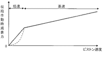
反対に、シリンダ1に対してピストン2が図1中下方へ移動する緩衝器Dの収縮作動時の作動について説明する。緩衝器Dの収縮作動時には、ピストン2が圧側室R2を圧縮するので、圧側室R2から伸側室R1へ液体が移動しようとする。シリンダ1に対するピストン2の移動速度であるピストン速度が低速域では、圧側室R2の圧力が圧側リーフバルブ9および圧側減衰バルブ5の開弁圧に達せず、第二リーフバルブ15の外環15bが第一リーフバルブ14から離間して、圧側オリフィス14bを開放する。よって、液体は、オリフィスOおよび圧側オリフィス14bを通過して圧側室R2から伸側室R1へ移動する。なお、ピストンロッド3がシリンダ1内に侵入して、シリンダ1内でピストンロッド3の侵入分の液体が過剰となるが、伸側室R1内の圧力上昇により環状凹部10a内の圧力が上昇し、チェックシール12bが開いて、過剰分の液体をリザーバRへ逃がす。このように、緩衝器Dの収縮作動時であってピストン速度が低速域では、圧側室R2内の液体は、圧側室R2とリザーバRとを仕切るバルブケース4にはオリフィスが設けられていないため、リザーバRへ直接に移動しない。よって、緩衝器Dの収縮作動時であってピストン速度が低速域では、圧側室R2からリザーバRへ直接圧力が逃げないので、圧側室R2内の圧力が速やかに上昇する。したがって、この場合の緩衝器Dの減衰力特性(ピストン速度に対する減衰力の特性)は、図6に示すように、図中破線で示すオリフィス特性よりも立ち上がりが速やかとなる図中実線で示すリニア特性に近い特性となって、減衰力が応答性よく立ち上がる特性となる。以上、本発明の緩衝器Dによれば、圧側の減衰力の発生応答性を向上できる。なお、チェックシール12bを設けない場合にあっても、圧側室R2内の圧力上昇が速やかとなる点で変わりはないので、緩衝器Dにおける収縮作動時の減衰力発生応答性が向上する。
On the contrary, the operation at the time of the contraction operation of the shock absorber D in which the
また、緩衝器Dの圧側の減衰力の発生応答性の向上のみを志向する場合、圧側オリフィス14bを省略してもよい。しかしながら、収縮作動時のみ有効となる片効きの圧側オリフィス14bを設けると圧側室R2内の圧力上昇が過剰となるのを阻止しつつ、伸縮の両側で独立した減衰力特性のチューニングが可能となる。
Further, in the case where only the improvement in the response of generating the damping force on the pressure side of the shock absorber D is intended, the
さらに、ピストン2に伸側室R1と圧側室R2とを連通するポート2dを設け、ピストン2の伸側室R1側にポート2dを開閉するとともにポート2dに通じる圧側オリフィス14bを有する第一リーフバルブ14を積層し、第一リーフバルブ14の伸側室R1側に圧側オリフィス14bを開閉する第二リーフバルブ15を積層すると、簡単な構成で片効きの圧側オリフィス14bを構成できる。なお、圧側オリフィスの構成は、前述した構成に限定されるものではなく、圧側ポート2dの開閉を圧側リーフバルブ9以外の構造のバルブを用いてもよい。たとえば、圧側オリフィスによる伸側室R1と圧側室R2の連通を確保する場合、圧側ポート2dを利用せずにこれに独立して連通するようにしてもよく、圧側オリフィスを開閉するバルブを圧側ポート2dを開閉するバルブに統合せずに独立させてもよい。
Further, a
また、第二リーフバルブ15は、内環15aと、圧側オリフィス14bを開閉する外環15bと、内環15aと外環15bとを接続する腕部15cとを備えて構成されると、腕部15cの幅と設置数の設定によって、圧側オリフィス14bを開放する開弁圧を容易にチューニング可能となる。
The
戻って、ピストン速度が高速域に達すると、圧側室R2内の圧力が圧側リーフバルブ9および圧側減衰バルブ5の開弁圧に達して開弁し、圧側ポート2dおよび排出ポート4bが開放される。この場合、液体は、圧側室R2から圧側ポート2dを介して伸側室R1へ移動するとともに、排出ポート4bを介してリザーバRへ移動する。すると、緩衝器Dの減衰力特性は、図7に示すように、オリフィスOおよび圧側オリフィス14bを液体が通過する状態における特性から、傾きが小さくなるもののピストン速度の増加に伴って比例するバルブ特有の特性となる。
Returning, when the piston speed reaches the high speed range, the pressure in the pressure side chamber R2 reaches the valve opening pressure of the pressure
以上で、本発明の実施の形態についての説明を終えるが、本発明の範囲は図示されまたは説明された詳細そのものには限定されないことは勿論である。 This is the end of the description of the embodiment of the present invention, but the scope of the present invention is of course not limited to the details shown or described.
1・・・シリンダ、2・・・ピストン、2d・・・圧側ポート(ポート)、3・・・ピストンロッド、4・・・バルブケース、5・・・圧側減衰バルブ、6・・・逆止弁、14・・・第一リーフバルブ、14b・・・圧側オリフィス、15・・・第二リーフバルブ、15a・・・内環、15b・・・外環、15c・・・腕部、D・・・緩衝器、L・・・液室、O・・・オリフィス、R・・・リザーバ、R1・・・伸側室、R2・・・圧側室、
DESCRIPTION OF
Claims (4)
前記シリンダ内に摺動自在に挿入されるピストンと、
前記シリンダ内に移動自在に挿入されて前記ピストンに連結されるピストンロッドと、
リザーバと前記シリンダ内の液室とを仕切るバルブケースと、
前記液室内に前記ピストンで区画される伸側室と圧側室と、
前記伸側室と前記圧側室とを連通するオリフィスとを備え、
前記バルブケースに、前記圧側室から前記リザーバへ向かう液体の流れのみを許容して前記液体の流れに抵抗を与える圧側減衰バルブと前記リザーバから前記圧側室へ向かう液体の流れのみを許容する逆止弁のみを設けた
ことを特徴とする緩衝器。 A cylinder,
A piston slidably inserted into the cylinder;
A piston rod movably inserted into the cylinder and coupled to the piston;
A valve case for partitioning the reservoir and the liquid chamber in the cylinder;
An extension side chamber and a pressure side chamber defined by the piston in the liquid chamber;
An orifice communicating the extension side chamber and the compression side chamber;
The valve case allows only a flow of liquid from the pressure side chamber to the reservoir and gives resistance to the flow of the liquid, and a check that allows only a flow of liquid from the reservoir to the pressure side chamber. A shock absorber characterized by providing only a valve.
ことを特徴とする請求項1に記載の緩衝器。 The extension side chamber and the pressure side chamber communicate with each other, and a one-sided pressure side orifice that provides resistance to the liquid flow by allowing only the flow of liquid from the pressure side chamber to the extension side chamber is provided. The shock absorber according to claim 1.
前記ピストンの前記伸側室側に積層されて前記ポートを開閉するとともに、前記ポートに通じる小孔でなる前記圧側オリフィスを有する第一リーフバルブと、
前記第一リーフバルブの前記伸側室側に積層されて前記圧側オリフィスを開閉する第二リーフバルブとを備えた
ことを特徴とする請求項2に記載の緩衝器。 The piston has a port communicating the extension side chamber and the pressure side chamber,
A first leaf valve that is stacked on the extension side chamber side of the piston to open and close the port, and has the pressure side orifice formed by a small hole that communicates with the port;
The shock absorber according to claim 2, further comprising: a second leaf valve that is stacked on the extension side chamber side of the first leaf valve and opens and closes the pressure side orifice.
ことを特徴とする請求項3に記載の緩衝器。 The second leaf valve includes an inner ring, an outer ring that is disposed on an outer peripheral side of the inner ring and opens and closes the compression side orifice, and an arm portion that connects the inner ring and the outer ring. The shock absorber according to claim 3.
Priority Applications (1)
| Application Number | Priority Date | Filing Date | Title |
|---|---|---|---|
| JP2015117182A JP6514573B2 (en) | 2015-06-10 | 2015-06-10 | Shock absorber |
Applications Claiming Priority (1)
| Application Number | Priority Date | Filing Date | Title |
|---|---|---|---|
| JP2015117182A JP6514573B2 (en) | 2015-06-10 | 2015-06-10 | Shock absorber |
Publications (2)
| Publication Number | Publication Date |
|---|---|
| JP2017002988A true JP2017002988A (en) | 2017-01-05 |
| JP6514573B2 JP6514573B2 (en) | 2019-05-15 |
Family
ID=57752653
Family Applications (1)
| Application Number | Title | Priority Date | Filing Date |
|---|---|---|---|
| JP2015117182A Active JP6514573B2 (en) | 2015-06-10 | 2015-06-10 | Shock absorber |
Country Status (1)
| Country | Link |
|---|---|
| JP (1) | JP6514573B2 (en) |
Citations (6)
| Publication number | Priority date | Publication date | Assignee | Title |
|---|---|---|---|---|
| JPH0297740A (en) * | 1988-09-30 | 1990-04-10 | Kayaba Ind Co Ltd | Damping force generating device for hydraulic shock absorber |
| JPH0893830A (en) * | 1994-09-28 | 1996-04-12 | Unisia Jecs Corp | Hydraulic buffer |
| JP2003042213A (en) * | 2001-07-31 | 2003-02-13 | Kayaba Ind Co Ltd | Hydraulic shock absorber |
| JP2004239285A (en) * | 2003-02-03 | 2004-08-26 | Kayaba Ind Co Ltd | Damper |
| JP5220560B2 (en) * | 2008-11-06 | 2013-06-26 | カヤバ工業株式会社 | Leaf valve |
| JP2015094365A (en) * | 2013-11-08 | 2015-05-18 | カヤバ工業株式会社 | Shock absorber |
-
2015
- 2015-06-10 JP JP2015117182A patent/JP6514573B2/en active Active
Patent Citations (6)
| Publication number | Priority date | Publication date | Assignee | Title |
|---|---|---|---|---|
| JPH0297740A (en) * | 1988-09-30 | 1990-04-10 | Kayaba Ind Co Ltd | Damping force generating device for hydraulic shock absorber |
| JPH0893830A (en) * | 1994-09-28 | 1996-04-12 | Unisia Jecs Corp | Hydraulic buffer |
| JP2003042213A (en) * | 2001-07-31 | 2003-02-13 | Kayaba Ind Co Ltd | Hydraulic shock absorber |
| JP2004239285A (en) * | 2003-02-03 | 2004-08-26 | Kayaba Ind Co Ltd | Damper |
| JP5220560B2 (en) * | 2008-11-06 | 2013-06-26 | カヤバ工業株式会社 | Leaf valve |
| JP2015094365A (en) * | 2013-11-08 | 2015-05-18 | カヤバ工業株式会社 | Shock absorber |
Also Published As
| Publication number | Publication date |
|---|---|
| JP6514573B2 (en) | 2019-05-15 |
Similar Documents
| Publication | Publication Date | Title |
|---|---|---|
| JP5941359B2 (en) | Buffer valve structure | |
| JP4898563B2 (en) | piston | |
| JP5787961B2 (en) | Shock absorber | |
| JP2008082491A (en) | Valve structure for shock absorber | |
| US11199241B2 (en) | Damper | |
| JP6188207B2 (en) | Cylinder device | |
| JP2017026040A (en) | Shock absorber | |
| JP2019143729A5 (en) | ||
| JP6487784B2 (en) | Shock absorber | |
| JP2012255467A5 (en) | ||
| JP2011080573A (en) | Valve structure of shock absorber | |
| JP6063312B2 (en) | Shock absorber | |
| JP2011257002A (en) | Shock absorber | |
| JP2014062643A5 (en) | ||
| JP2017002988A (en) | Shock absorber | |
| JP7111836B2 (en) | buffer | |
| JP6565442B2 (en) | Cylinder device | |
| JP5481227B2 (en) | Double cylinder type hydraulic shock absorber | |
| KR102614825B1 (en) | Shock absorber | |
| JP5106347B2 (en) | Hydraulic buffer | |
| JP2012167688A (en) | Valve structure | |
| JP5220560B2 (en) | Leaf valve | |
| JPS5817140Y2 (en) | hydraulic shock absorber | |
| JP5281326B2 (en) | valve | |
| JP2006183775A (en) | Hydraulic shock absorber |
Legal Events
| Date | Code | Title | Description |
|---|---|---|---|
| A621 | Written request for application examination |
Free format text: JAPANESE INTERMEDIATE CODE: A621 Effective date: 20171219 |
|
| A977 | Report on retrieval |
Free format text: JAPANESE INTERMEDIATE CODE: A971007 Effective date: 20181030 |
|
| A131 | Notification of reasons for refusal |
Free format text: JAPANESE INTERMEDIATE CODE: A131 Effective date: 20181113 |
|
| A521 | Request for written amendment filed |
Free format text: JAPANESE INTERMEDIATE CODE: A523 Effective date: 20190109 |
|
| TRDD | Decision of grant or rejection written | ||
| A01 | Written decision to grant a patent or to grant a registration (utility model) |
Free format text: JAPANESE INTERMEDIATE CODE: A01 Effective date: 20190319 |
|
| A61 | First payment of annual fees (during grant procedure) |
Free format text: JAPANESE INTERMEDIATE CODE: A61 Effective date: 20190412 |
|
| R151 | Written notification of patent or utility model registration |
Ref document number: 6514573 Country of ref document: JP Free format text: JAPANESE INTERMEDIATE CODE: R151 |
|
| S533 | Written request for registration of change of name |
Free format text: JAPANESE INTERMEDIATE CODE: R313533 |
|
| R350 | Written notification of registration of transfer |
Free format text: JAPANESE INTERMEDIATE CODE: R350 |