JP2017001801A - Interactive elevator - Google Patents
Interactive elevator Download PDFInfo
- Publication number
- JP2017001801A JP2017001801A JP2015116669A JP2015116669A JP2017001801A JP 2017001801 A JP2017001801 A JP 2017001801A JP 2015116669 A JP2015116669 A JP 2015116669A JP 2015116669 A JP2015116669 A JP 2015116669A JP 2017001801 A JP2017001801 A JP 2017001801A
- Authority
- JP
- Japan
- Prior art keywords
- response message
- user
- voice
- wireless communication
- communication device
- Prior art date
- Legal status (The legal status is an assumption and is not a legal conclusion. Google has not performed a legal analysis and makes no representation as to the accuracy of the status listed.)
- Granted
Links
Images


Abstract
Description
本発明の実施形態は、対話型エレベータに関する。 Embodiments of the present invention relate to interactive elevators.
従来、利用者と対話可能な対話型エレベータが知られている。従来の対話型エレベータでは、利用者は、携帯端末を操作することにより、携帯端末にカゴの運行情報を表示したり、呼びを登録したりすることが可能である。これらのサービスは、携帯端末の操作に慣れた利用者にとっては便利であった。しかしながら、携帯端末の操作に不慣れな利用者(高齢者など)や目の不自由な利用者には、携帯端末の操作が煩雑であり、これらのサービスを受けることは困難であった。 Conventionally, an interactive elevator that can interact with a user is known. In the conventional interactive elevator, the user can display the operation information of the car or register the call on the mobile terminal by operating the mobile terminal. These services were convenient for users accustomed to operating portable terminals. However, it is difficult for users (such as elderly people) who are unfamiliar with the operation of the mobile terminal and visually impaired users to operate the mobile terminal and receive these services.
利用者と音声により対話可能な対話型エレベータを提供する。 To provide an interactive elevator that can communicate with users by voice.
一実施形態に係る対話型エレベータは、無線通信装置と、音声認識部と、応答メッセージ生成部と、音声合成部と、スピーカと、を備える。無線通信装置は、利用者の携帯端末から、利用者が入力した音声データを無線で受信する。音声認識部は、音声データに基づいて、利用者からのメッセージの内容を認識する。応答メッセージ生成部は、利用者からのメッセージに応答する応答メッセージを生成する。音声合成部は、応答メッセージの音声データを生成する。スピーカは、応答メッセージの音声データを入力され、応答メッセージを音声出力する。無線通信装置は、応答メッセージの音声データを、携帯端末に送信する。 An interactive elevator according to an embodiment includes a wireless communication device, a voice recognition unit, a response message generation unit, a voice synthesis unit, and a speaker. The wireless communication device wirelessly receives voice data input by the user from the user's mobile terminal. The voice recognition unit recognizes the content of the message from the user based on the voice data. The response message generation unit generates a response message in response to the message from the user. The voice synthesizer generates voice data of the response message. The speaker receives voice data of the response message and outputs the response message as voice. The wireless communication device transmits the voice data of the response message to the mobile terminal.
以下、本発明の実施形態について図面を参照して説明する。 Embodiments of the present invention will be described below with reference to the drawings.
(第1実施形態)
第1実施形態に係る対話型エレベータについて、図1〜図3を参照して説明する。本実施形態に係る対話型エレベータは、利用者と音声により対話が可能である。利用者は、携帯端末Tを介して、対話型エレベータと対話することができる。まず、携帯端末Tについて説明する。
(First embodiment)
The interactive elevator according to the first embodiment will be described with reference to FIGS. The interactive elevator according to the present embodiment can interact with a user by voice. The user can interact with the interactive elevator via the mobile terminal T. First, the mobile terminal T will be described.
携帯端末Tは、無線通信部、マイク、スピーカ、及びディスプレイを備える。利用者が携帯端末Tに向かって話すと、携帯端末Tのマイクが利用者の声を拾い、利用者の声が音声データとして携帯端末Tに入力される。このように、利用者は、質問や要求などのメッセージを、携帯端末Tに音声入力することができる。携帯端末Tは、利用者から入力された音声データを、自身のIDと共に、対話型エレベータに無線で送信する。携帯端末Tは、例えば、スマートフォン、携帯電話、及びタブレット端末であるが、これに限られない。 The portable terminal T includes a wireless communication unit, a microphone, a speaker, and a display. When the user speaks toward the portable terminal T, the microphone of the portable terminal T picks up the voice of the user, and the voice of the user is input to the portable terminal T as voice data. In this manner, the user can input a message such as a question or a request to the mobile terminal T by voice. The portable terminal T wirelessly transmits the voice data input from the user to the interactive elevator together with its own ID. Although the portable terminal T is a smart phone, a mobile phone, and a tablet terminal, for example, it is not restricted to this.
本実施形態に係る対話型エレベータは、利用者からのメッセージに応答するメッセージ(応答メッセージ)を、音声出力する。ここで、図1は、本実施形態に係る対話型エレベータの一例を示す図である。図1に示すように、この対話型エレベータは、乗場1と、カゴ2と、対話制御装置3と、制御盤4と、を備える。
The interactive elevator according to the present embodiment outputs a message (response message) in response to a message from the user by voice. Here, FIG. 1 is a diagram illustrating an example of an interactive elevator according to the present embodiment. As shown in FIG. 1, the interactive elevator includes a
乗場1には、乗場ドア11と、操作盤12と、無線通信装置13と、スピーカ14と、が設けられる。乗場ドア11は、利用者がカゴ2に乗り降りするための乗場1側のドアである。操作盤12は、乗場呼びを登録するための乗場呼び釦を備える。
The
無線通信装置13は、乗場1にいる利用者の携帯端末Tと無線で通信する。無線通信装置13は、通信エリアに乗場1が含まれるように、所定の位置に設けられる。図1の例では、無線通信装置13は、乗場1の壁面に設けられているが、操作盤12に内蔵されてもよいし、乗場1の天井に設けられてもよい。
The
無線通信装置13と携帯端末Tとの間の通信規格は、任意に選択可能である。通信規格は、例えば、Wi−Fi(登録商標)、ZigBee(登録商標)、Bluetooth(登録商標)であるが、これに限られない。
A communication standard between the
無線通信装置13は、通信エリア内に入ってきた携帯端末Tを検出し、検出した携帯端末Tと接続する。したがって、利用者が乗場1にやってくると、利用者の携帯端末Tは、無線通信装置13と自動的に接続される。
The
また、無線通信装置13は、接続中の携帯端末Tが通信エリア外に出て行くと、出て行った携帯端末Tとの接続を解除する。したがって、利用者が乗場1から出て行くと、利用者の携帯端末Tは、無線通信装置13との接続を自動的に解除される。
Further, when the connected mobile terminal T goes out of the communication area, the
無線通信装置13は、接続中の携帯端末Tとの間で音声データを送受信する。無線通信装置13は、接続中の携帯端末Tから音声データを受信すると、受信した音声データ及び送信元の携帯端末TのIDを、自身のIDと共に、対話制御装置3に入力する。
The
スピーカ14は、乗場1にいる利用者に応答メッセージを音声出力する。スピーカ14は、乗場1にいる利用者に応答メッセージが聞こえるように、所定の位置に設けられる。図1の例では、スピーカ14は、乗場1の壁面に設けられているが、操作盤12に内蔵されてもよいし、乗場1の天井に設けられてもよい。また、スピーカ14は、乗場1に複数設けられてもよい。
The
スピーカ14は、後述する音声合成部34から、応答メッセージの音声データを入力され、音声データを合成音声として出力する。これにより、乗場1にいる利用者に対して、応答メッセージが音声出力される。
The
カゴ2は、カゴドア21と、操作盤22と、無線通信装置23と、スピーカ24と、を備える。カゴドア21は、利用者がカゴ2に乗り降りするためのカゴ2側のドアである。操作盤22は、戸開釦、戸閉釦、及びカゴ呼びを登録するための各階床の行先階釦を備える。
The
無線通信装置23は、カゴ2内の利用者の携帯端末Tと無線で通信する。無線通信装置23は、通信エリアにカゴ2が含まれるように、所定の位置に設けられる。図1の例では、無線通信装置23は、カゴ2の壁面に設けられているが、操作盤22に内蔵されてもよいし、カゴ2の天井に設けられてもよい。
The
無線通信装置23と携帯端末Tとの間の通信規格は、任意に選択可能である。通信規格は、例えば、Wi−Fi(登録商標)、ZigBee(登録商標)、Bluetooth(登録商標)であるが、これに限られない。
A communication standard between the
無線通信装置23は、通信エリア内に入ってきた携帯端末Tを検出し、検出した携帯端末Tと接続する。したがって、利用者がカゴ2に乗車すると、利用者の携帯端末Tは、無線通信装置23と自動的に接続される。
The
また、無線通信装置23は、接続中の携帯端末Tが通信エリア外に出て行くと、出て行った携帯端末Tとの接続を解除する。したがって、利用者がカゴ2から降車すると、利用者の携帯端末Tは、無線通信装置23との接続を自動的に解除される。
Further, when the connected mobile terminal T goes out of the communication area, the
無線通信装置23は、接続中の携帯端末Tとの間で音声データを送受信する。無線通信装置23は、接続中の携帯端末Tから音声データを受信すると、受信した音声データ及び送信元の携帯端末TのIDを、自身のIDと共に、対話制御装置3に入力する。
The
なお、図1の例では、対話型エレベータは、乗場1に設けられた無線通信装置13と、カゴ2に設けられた無線通信装置23と、をそれぞれ備えるが、無線通信装置13又は無線通信装置23のいずれか一方だけを備えてもよい。
In the example of FIG. 1, the interactive elevator includes a
スピーカ24は、カゴ2の利用者に応答メッセージを音声出力する。スピーカ24は、カゴ2の利用者に応答メッセージが聞こえるように、所定の位置に設けられる。図1の例では、スピーカ24は、カゴ2の壁面に設けられているが、操作盤22に内蔵されてもよいし、カゴ2の天井に設けられてもよい。
The
スピーカ24は、後述する音声合成部34から、応答メッセージの音声データを入力され、音声データを合成音声として出力する。これにより、カゴ2の利用者に対して、応答メッセージが音声出力される。
The
なお、図1の例では、対話型エレベータは、乗場1に設けられたスピーカ14と、カゴ2に設けられたスピーカ24と、をそれぞれ備えるが、スピーカ14又はスピーカ24のいずれか一方だけを備えてもよい。
In the example of FIG. 1, the interactive elevator includes the
対話制御装置3は、対話型エレベータによる利用者との対話を制御するコンピュータである。対話制御装置3は、カゴ2の運行を制御する制御盤4により構成されてもよいし、制御盤4に接続された他のコンピュータにより構成されてもよいし、中央管理センタに設置されたサーバにより構成されてもよい。いずれの場合も、対話制御装置3は、無線通信装置13,23及びスピーカ14,24と、有線又は無線で通信可能に接続される。
The
図1に示すように、対話制御装置3は、機能構成として、音声認識部31と、応答メッセージ生成部32と、運行情報取得部33と、音声合成部34と、を備える。各機能構成は、対話制御装置3を構成するコンピュータが、プログラムを実行することにより実現される。
As shown in FIG. 1, the
音声認識部31は、無線通信装置13,23から、利用者が入力した音声データと、携帯端末TのIDと、無線通信装置13,23のIDと、を入力される。音声認識部31は、入力された音声データに対して、隠れマルコフモデルなどを利用した既存の音声認識処理を実行し、利用者からのメッセージの内容を認識する。音声認識部31は、音声認識処理により得られたメッセージの内容を、応答メッセージ生成部32に入力する。
The
応答メッセージ生成部32は、音声認識部31からメッセージの内容を入力され、入力されたメッセージに応答する応答メッセージを生成する。応答メッセージは、既存の任意の質問応答方法を利用して生成することができる。応答メッセージ生成部32は、応答メッセージを生成するためのデータベースやインターネットに接続されているのが好ましい。
The response
応答メッセージ生成部32は、カゴ2の運行情報に基づいて応答メッセージを生成してもよい。これにより、応答メッセージ生成部32は、利用者からのカゴ2の運行に関する質問(例えば、「カゴはあとどのくらいで到着しますか?」という質問)に回答する応答メッセージを生成することができる。
The
運行情報取得部33は、応答メッセージ生成部32からの要求に応じて、或いは、定期的に、カゴ2の制御盤4から運行情報を取得する。運行情報には、カゴ2の現在位置(階床)、速度、昇降方向、重量、及び登録された呼びなどが含まれる。運行情報取得部33は、取得した運行情報を、応答メッセージ生成部32に入力する。これにより、応答メッセージ生成部32は、上記のような運行情報に基づく応答メッセージを生成することができる。
The operation
音声合成部34は、応答メッセージ生成部32から応答メッセージを入力され、入力された応答メッセージの音声データを生成する。応答メッセージの音声データとは、応答メッセージを読み上げる合成音声の波形を示す音声データのことである。このような、テキスト(応答メッセージ)から合成音声への変換は、既存の音声合成方法により行うことができる。音声合成部34は、生成した音声データをスピーカ14,24に入力する。
The
制御盤4は、カゴ2の運行(昇降、戸開、戸閉など)の制御、乗場呼び釦及び行先階釦からの入力に応じた呼びの登録、及びカゴ2の運行情報の収集などを行う。制御盤4は、収集した情報を、運行情報取得部33に入力する。
The control panel 4 controls the operation of the car 2 (elevation, door opening, door closing, etc.), registers the call according to the input from the hall call button and the destination floor button, and collects the operation information of the
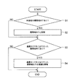
次に、本実施形態に係る対話型エレベータの動作について、図2及び図3を参照して詳細に説明する。図2は、無線通信装置13,23による携帯端末Tの接続処理を示すフローチャートである。以下では、無線通信装置13を例に説明する。無線通信装置13は無線LAN親機、携帯端末Tは無線LAN子機であるものとする。
Next, the operation of the interactive elevator according to the present embodiment will be described in detail with reference to FIGS. FIG. 2 is a flowchart showing connection processing of the portable terminal T by the
まず、無線通信装置13は、通信エリア内に未接続の携帯端末Tがあるか判定する(ステップS1)。具体的には、無線通信装置13は、ビーコンを送信し、ビーコンに応答した携帯端末TのIDを収集し、収集したIDに未接続のIDが含まれるか調べればよい。
First, the
未接続の携帯端末Tがなかった場合(ステップS1のNO)、処理はステップS3に進む。一方、未接続の携帯端末Tがあった場合(ステップS1のYES)、無線通信装置13は、発見した未接続の携帯端末Tと接続する(ステップS2)。この際、無線通信装置13は、新たに接続した携帯端末TのIDを、接続中の無線LAN子機のIDとして記憶する。また、新たに接続された携帯端末Tは、無線通信装置13のIDを、接続中の無線LAN親機のIDとして記憶する。その後、処理はステップS3に進む。
If there is no unconnected mobile terminal T (NO in step S1), the process proceeds to step S3. On the other hand, when there is an unconnected mobile terminal T (YES in step S1), the
次に、無線通信装置13は、接続中の携帯端末Tの中に、通信エリア外に出て行った携帯端末Tがあるか判定する(ステップS3)。例えば、無線通信装置13は、ある携帯端末Tから所定時間以上継続して信号を受信できなかった場合、その携帯端末Tは通信エリア外に出て行ったと判定すればよい。このような判定のために、無線通信装置13は、接続中の各携帯端末Tとの通信履歴を記憶しておくのが好ましい。
Next, the
通信エリア外に出て行った携帯端末Tがなかった場合(ステップS3のNO)、処理は終了する。一方、通信エリア外に出て行った携帯端末Tがあった場合(ステップS3のYES)、無線通信装置13は、通信エリア外に出て行った携帯端末Tとの接続を解除する(ステップ4)。そして、無線通信装置13は、接続中の無線LAN子機のIDから、接続を解除した携帯端末TのIDを削除する。
If there is no mobile terminal T that has gone out of the communication area (NO in step S3), the process ends. On the other hand, when there is a mobile terminal T that has gone out of the communication area (YES in step S3), the
無線通信装置13は、以上の処理を所定の時間間隔で繰り返す。無線通信装置13のこのような動作により、乗場1にやってきた利用者の携帯端末Tは、利用者が操作することなく、自動的に無線通信装置13に接続される。また、乗場1から出て行った利用者の携帯端末Tは、利用者が操作することなく、自動的に無線通信装置13との接続を解除される。
The
無線通信装置23についても同様である。すなわち、無線通信装置23は、ステップS1〜S4の接続処理を所定の時間間隔で繰り返す。これにより、カゴ2に乗車した利用者の携帯端末Tは、自動的に無線通信装置23に接続され、カゴ2から降車した利用者の携帯端末Tは、自動的に無線通信装置23との接続を解除される。
The same applies to the
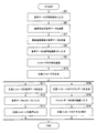
図3は、本実施形態に係る対話型エレベータと利用者との対話処理を示すフローチャートである。以下では、利用者が乗場1にいる場合を例に説明する。利用者の携帯端末Tは、上述の接続処理によって、無線通信装置13に接続されているものとする。
FIG. 3 is a flowchart showing a dialogue process between the interactive elevator and the user according to the present embodiment. Hereinafter, a case where the user is at the
利用者が携帯端末Tに向かって話すと、利用者の声が音声データとして携帯端末Tに入力される(ステップS5)。携帯端末Tは、音声データを入力されると、入力された音声データを自身のIDと共に、接続中の無線通信装置13に無線で送信する(ステップS6)。 When the user speaks toward the portable terminal T, the voice of the user is input to the portable terminal T as voice data (step S5). When the voice data is input, the portable terminal T wirelessly transmits the input voice data together with its own ID to the connected wireless communication device 13 (step S6).
このような処理を実現するために、携帯端末Tは、利用者から入力された音声データを無線通信装置13に送信するためのアプリケーションを予めインストールされているのが好ましい。このアプリケーションは、携帯端末Tのバックグラウンドで常時起動していてもよいし、無線通信装置13に接続されることをトリガーにして起動してもよい。
In order to realize such processing, it is preferable that the portable terminal T is preinstalled with an application for transmitting voice data input from the user to the
無線通信装置13は、携帯端末Tが送信した音声データを受信する(ステップS7)。無線通信装置13は、音声データの受信処理を常時行なってもよいし、消費電力を抑制するために所定の時間間隔で行なってもよい。
The
無線通信装置13は、音声データを受信すると、送信元の携帯端末TのIDを確認し、送信元の携帯端末Tが接続中の携帯端末Tであるか確認する。送信元の携帯端末Tが接続中の携帯端末Tであった場合、無線通信装置13は、音声データと、送信元の携帯端末TのIDと、を自身のIDと共に、音声認識部31に入力する(ステップS8)。なお、送信元の携帯端末Tが未接続の携帯端末Tであった場合、無線通信装置13は、上述の接続処理を実行すればよい。
When the
音声認識部31は、音声データを入力されると、音声認識処理を実行し、利用者からのメッセージの内容を認識する(ステップS9)。音声認識部31は、認識したメッセージの内容を、携帯端末TのID及び無線通信装置13のIDと共に、応答メッセージ生成部32に入力する。
When voice data is input, the
応答メッセージ生成部32は、入力されたメッセージの内容に基づいて、応答メッセージを生成する(ステップS10)。
The
この際、応答メッセージ生成部32は、無線通信装置13のIDを利用して応答メッセージを生成してもよい。無線通信装置13のIDにより、利用者のいる階床がわかるため、利用者の階床に応じた応答メッセージを生成することができる。
At this time, the
例えば、応答メッセージ生成部32は、利用者からの「カゴはあとどのくらいで到着しますか?」という質問に対して、運行情報と、利用者のいる階床と、に基づいて、カゴが到着するまでの時間を計算し、「カゴはあと20秒で到着します」という応答メッセージを生成することができる。
For example, the response
応答メッセージ生成部32は、生成した応答メッセージを、携帯端末TのID及び無線通信装置13のIDと共に、音声合成部34に入力する。
The
音声合成部34は、応答メッセージ生成部32から応答メッセージを入力されると、音声合成処理を実行し、応答メッセージの音声データを生成する(ステップS11)。そして、音声合成部34は、応答メッセージと共に入力された無線通信装置13のIDを確認し、利用者がいる階床の乗場1に設置されたスピーカ14を特定し、特定されたスピーカ14に音声データを入力する(ステップS12)。
When the response message is input from the
音声合成部34は、音声データを入力するスピーカ14を特定するために、無線通信装置13のIDと対応するスピーカ14を予め記憶していてもよいし、無線通信装置13のIDと対応するスピーカ14を記憶したデータベースを参照してもよい。
The
スピーカ14は、音声合成部34から音声データを入力されると、入力された音声データを合成音声として出力する。これにより、スピーカ14から、応答メッセージが音声出力される(ステップS13)。
When the voice data is input from the
以上説明した通り、本実施形態に係る対話型エレベータは、携帯端末Tを介して、利用者と音声により対話することができる。音声により対話が可能なため、携帯端末Tの煩雑な操作は不要である。したがって、携帯端末Tの操作に不慣れな利用者(高齢者)や目の不自由な利用者であっても、対話型エレベータと容易に対話し、情報提供などのサービスを受けることができる。 As described above, the interactive elevator according to the present embodiment can interact with the user by voice via the mobile terminal T. Since dialogue is possible by voice, complicated operation of the portable terminal T is not necessary. Therefore, even a user who is unaccustomed to the operation of the mobile terminal T (elderly person) or a user who is blind is able to easily interact with the interactive elevator and receive services such as providing information.
また、本実施形態に係る対話型エレベータは、カゴ2の到着を待っている利用者と対話することにより、利用者が感じる待ち時間の長さを軽減することができる。
Further, the interactive elevator according to the present embodiment can reduce the length of the waiting time felt by the user by interacting with the user waiting for the arrival of the
なお、以上の説明において、応答メッセージは、スピーカ14,24から音声出力されたが、利用者の携帯端末Tから音声出力されてもよい。この場合、対話型エレベータは、スピーカ14,24を備えなくてもよい。応答メッセージを携帯端末Tから音声出力する方法として、以下の方法が考えられる。
In the above description, the response message is output from the
まず、応答メッセージの音声データを生成した音声合成部34は、応答メッセージと共に入力された無線通信装置13のIDを確認し、このIDを有する無線通信装置13に、音声データと、携帯端末TのIDと、を入力する。
First, the
次に、音声データを入力された無線通信装置13は、音声データと共に入力された携帯端末TのIDを確認し、このIDを有する携帯端末Tに、音声データを無線で送信する。
Next, the
そして、音声データを受信した携帯端末Tは、自身のスピーカから応答メッセージを音声出力する。これにより、利用者は、対話型エレベータからの応答メッセージを、自身の携帯端末Tから聞くことができる。 And the portable terminal T which received audio | voice data outputs a response message by audio | voice from its speaker. Thereby, the user can hear the response message from the interactive elevator from his portable terminal T.
また、対話型エレベータは、利用者から音声入力されたメッセージにより、呼びを登録可能であってもよい。例えば、カゴ2に乗車した利用者から「1階へ行きます」というメッセージを入力された場合、対話型エレベータは、応答メッセージを音声出力すると共に、カゴ2に対して1階へのカゴ呼びを登録してもよい。これにより、利用者は、音声によってカゴ2を操作することができる。
Further, the interactive elevator may be able to register a call by a message inputted by voice from a user. For example, when a message “going to the first floor” is input from a user who has boarded the
(第2実施形態)
第2実施形態に係る対話型エレベータについて、図4及び図5を参照して説明する。本実施形態に係る対話型エレベータは、応答メッセージをテキスト表示する。図4は、本実施形態に係る対話型エレベータの一例を示す図である。図4に示すように、この対話型エレベータは、表示装置15,25を備える。また、対話制御装置3は、機能構成として、テキストデータ生成部35を備える。他の構成は、第1実施形態と同様である。
(Second Embodiment)
The interactive elevator which concerns on 2nd Embodiment is demonstrated with reference to FIG.4 and FIG.5. The interactive elevator according to the present embodiment displays a response message as text. FIG. 4 is a diagram illustrating an example of an interactive elevator according to the present embodiment. As shown in FIG. 4, the interactive elevator includes
表示装置15は、乗場1にいる利用者に応答メッセージをテキスト表示する。表示装置15は、例えば、LCD(液晶ディスプレイ)、CRT(ブラウン管)、及びPDP(プラズマディスプレイ)であるが、これに限られない。表示装置15は、乗場1にいる利用者に応答メッセージが見えるように、所定の位置に設けられる。図4の例では、表示装置15は、乗場ドア11の上方に設けられているが、操作盤12に設けられてもよい。
The
表示装置15は、後述するテキストデータ生成部35から、応答メッセージのテキストデータを入力されると、応答メッセージをテキスト表示する。これにより、乗場1にいる利用者は、応答メッセージを読むことができる。
When the text data of the response message is input from the text
表示装置25は、カゴ2内の利用者に応答メッセージをテキスト表示する。表示装置25は、例えば、LCD、CRT、及びPDPであるが、これに限られない。表示装置25は、カゴ2内の利用者に応答メッセージが見えるように、所定の位置に設けられる。図4の例では、表示装置25は、カゴドア21の上方に設けられているが、操作盤22に設けられてもよい。
The
表示装置25は、後述するテキストデータ生成部35から、応答メッセージのテキストデータを入力されると、応答メッセージをテキスト表示する。これにより、カゴ2内の利用者は、応答メッセージを読むことができる。
When the text data of the response message is input from the text
なお、図4の例では、対話型エレベータは、乗場1に設けられた表示装置15と、カゴ2に設けられた表示装置25と、をそれぞれ備えるが、表示装置15又は表示装置25のいずれか一方だけを備えてもよい。
In the example of FIG. 4, the interactive elevator includes a
テキストデータ生成部35は、応答メッセージ生成部32から応答メッセージを入力され、入力された応答メッセージのテキストデータを生成する。応答メッセージのテキストデータとは、応答メッセージをテキストで表示するための所定の形式を備えたデータのことである。テキストデータ生成部35は、生成したテキストデータを表示装置15,25に入力する。
The text
図5は、本実施形態に係る対話型エレベータと利用者との対話処理を示すフローチャートである。図5のステップS5〜S13は、第1実施形態と同様である。以下では、ステップS14〜ステップS16について説明する。また、第1実施形態の説明と同様、利用者が乗場1にいる場合を例に説明する。
FIG. 5 is a flowchart showing dialogue processing between the interactive elevator and the user according to the present embodiment. Steps S5 to S13 in FIG. 5 are the same as in the first embodiment. Below, step S14-step S16 are demonstrated. As in the description of the first embodiment, a case where the user is at the
本実施形態において、応答メッセージ生成部32は、生成した応答メッセージを、携帯端末TのID及び無線通信装置13のIDと共に、音声合成部34及びテキストデータ生成部35に入力する。
In the present embodiment, the
テキストデータ生成部35は、応答メッセージ生成部32から応答メッセージを入力されると、応答メッセージのテキストデータを生成する(ステップS14)。そして、テキストデータ生成部35は、応答メッセージと共に入力された無線通信装置13のIDを確認し、利用者がいる階床の乗場1に設置された表示装置15を特定し、特定された表示装置15にテキストデータを入力する(ステップS15)。
When the response message is input from the response
テキストデータ生成部35は、テキストデータを入力する表示装置15を特定するために、無線通信装置13のIDと対応する表示装置15を予め記憶していてもよいし、無線通信装置13のIDと対応する表示装置15を記憶したデータベースを参照してもよい。
The text
表示装置15は、テキストデータ生成部35からテキストデータを入力されると、入力されたテキストデータをテキストとして表示する。これにより、表示装置15に応答メッセージがテキスト表示される(ステップS16)。
When the text data is input from the text
以上説明した通り、本実施形態に係る対話型エレベータは、応答メッセージをテキスト表示することができる。このため、利用者は、音声出力された応答メッセージを聞き逃しても、応答メッセージを確認することができる。 As described above, the interactive elevator according to the present embodiment can display the response message in text. Therefore, the user can confirm the response message even if he / she misses the response message output by voice.
なお、以上の説明において、応答メッセージは、表示装置15,25にテキスト表示されたが、利用者の携帯端末Tにテキスト表示されてもよい。この場合、対話型エレベータは、表示装置15,25を備えなくてもよい。応答メッセージを携帯端末Tにテキスト表示する方法として、以下の方法が考えられる。
In the above description, the response message is displayed in text on the
まず、応答メッセージのテキストデータを生成したテキストデータ生成部35は、応答メッセージと共に入力された無線通信装置13のIDを確認し、このIDを有する無線通信装置13に、テキストデータと、携帯端末TのIDと、を入力する。
First, the text
次に、テキストデータを入力された無線通信装置13は、テキストデータと共に入力された携帯端末TのIDを確認し、このIDを有する携帯端末Tに、テキストデータを無線で送信する。
Next, the
そして、テキストデータを受信した携帯端末Tは、自身の表示装置に応答メッセージをテキスト表示する。これにより、利用者は、対話型エレベータからの応答メッセージを、自身の携帯端末Tで見ることができる。 Then, the mobile terminal T that has received the text data displays the response message in text on its display device. Thereby, the user can see the response message from the interactive elevator on his / her mobile terminal T.
(第3実施形態)
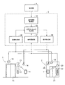
第3実施形態に係る対話型エレベータについて、図6を参照して説明する。本実施形態に係る対話型エレベータは、カメラで撮影した乗場1やカゴ2内の画像を用いて、応答メッセージを生成する。
(Third embodiment)
An interactive elevator according to the third embodiment will be described with reference to FIG. The interactive elevator according to the present embodiment generates a response message using the images in the
図6は、本実施形態に係る対話型エレベータの一例を示す図である。図6に示すように、この対話型エレベータは、カメラ16,26を備える。また、対話制御装置3は、機能構成として、画像処理部36を備える。他の構成は、第1実施形態と同様である。
FIG. 6 is a diagram illustrating an example of an interactive elevator according to the present embodiment. As shown in FIG. 6, the interactive elevator includes
カメラ16は、乗場1を撮影する。カメラ16は、乗場1を撮影可能なように、乗場1の天井や壁に設けられる。カメラ16は、撮影した画像の画像データを画像処理部36に入力する。
The
カメラ26は、カゴ2内を撮影する。カメラ26は、カゴ2内を撮影可能なように、カゴ2の天井や壁に設けられる。カメラ26は、撮影した画像の画像データを画像処理部36に入力する。
The
なお、図6の例では、対話型エレベータは、乗場1に設けられたカメラ16と、カゴ2に設けられたカメラ26と、をそれぞれ備えるが、カメラ16又はカメラ26のいずれか一方だけを備えてもよい。
In the example of FIG. 6, the interactive elevator includes the
画像処理部36は、カメラ16,26から画像データを入力され、入力された画像データに対して画像処理を実行する。画像処理により、例えば、利用者の人数、利用者の位置、弱者(けが人、病人、高齢者など)の有無、などの情報が得られる。画像処理部36は、画像処理により得られた情報を、応答メッセージ生成部32に入力する。
The
本実施形態において、応答メッセージ生成部32は、画像処理部36から入力された情報を利用して、応答メッセージを生成する。例えば、応答メッセージ生成部32は、利用者からの「カゴに何人乗れますか?」という質問に対して、画像処理部36から入力されたカゴ2内の利用者の人数に基づいてカゴ2に乗れる利用者の人数を計算し、「あと二人乗れます」という応答メッセージを生成することができる。
In the present embodiment, the response
以上説明したように、本実施形態に係る対話型エレベータは、カメラ16,26で撮影した乗場1やカゴ2内の画像から得られる情報を利用して、応答メッセージを生成することができる。これにより、乗場1やカゴ2内のリアルタイムの状況を反映した、より詳細な応答メッセージを生成することができる。
As described above, the interactive elevator according to the present embodiment can generate a response message using information obtained from the images in the
なお、本発明は上記各実施形態そのままに限定されるものではなく、実施段階ではその要旨を逸脱しない範囲で構成要素を変形して具体化できる。また、上記各実施形態に開示されている複数の構成要素を適宜組み合わせることによって種々の発明を形成できる。また例えば、各実施形態に示される全構成要素からいくつかの構成要素を削除した構成も考えられる。さらに、異なる実施形態に記載した構成要素を適宜組み合わせてもよい。 Note that the present invention is not limited to the above-described embodiments as they are, and can be embodied by modifying the components without departing from the scope of the invention in the implementation stage. Moreover, various inventions can be formed by appropriately combining a plurality of constituent elements disclosed in the above embodiments. Further, for example, a configuration in which some components are deleted from all the components shown in each embodiment is also conceivable. Furthermore, you may combine suitably the component described in different embodiment.
1:乗場、2:カゴ、3:対話制御装置、4:制御盤、11:乗場ドア、12:操作盤、13:無線通信装置、14:スピーカ、15:表示装置、16:カメラ、21:カゴドア、22:操作盤、23:無線通信装置、24:スピーカ、25:表示装置、26:カメラ、31:音声認識部、32:応答メッセージ生成部、33:運行情報取得部、34:音声合成部、35:テキストデータ生成部、36:画像処理部 1: landing, 2: basket, 3: dialog control device, 4: control panel, 11: landing door, 12: operation panel, 13: wireless communication device, 14: speaker, 15: display device, 16: camera, 21: Basket door, 22: operation panel, 23: wireless communication device, 24: speaker, 25: display device, 26: camera, 31: voice recognition unit, 32: response message generation unit, 33: operation information acquisition unit, 34: voice synthesis Part 35: text data generation part 36: image processing part
Claims (4)
前記音声データに基づいて、前記利用者からのメッセージの内容を認識する音声認識部と、
前記利用者からの前記メッセージに応答する応答メッセージを生成する応答メッセージ生成部と、
前記応答メッセージの音声データを生成する音声合成部と、
前記応答メッセージの前記音声データを入力され、前記応答メッセージを音声出力するスピーカと、
を備え、
前記無線通信装置は、前記応答メッセージの前記音声データを、前記携帯端末に送信する
対話型エレベータ。 A wireless communication device that wirelessly receives voice data input by the user from a mobile terminal of the user;
A voice recognition unit for recognizing the content of a message from the user based on the voice data;
A response message generator for generating a response message in response to the message from the user;
A voice synthesizer for generating voice data of the response message;
A speaker that receives the audio data of the response message and outputs the response message as audio;
With
The wireless communication apparatus is an interactive elevator that transmits the voice data of the response message to the mobile terminal.
請求項1に記載の対話型エレベータ。 The interactive elevator according to claim 1, wherein the response message generation unit generates the response message based on the content of the message and operation information.
前記テキストデータを入力され、前記応答メッセージをテキスト表示する表示装置と、
を備える請求項1又は請求項2に記載の対話型エレベータ。 A text data generation unit that generates text data of the response message;
A display device that receives the text data and displays the response message as text;
An interactive elevator according to claim 1 or 2, comprising:
前記カメラの画像データに画像処理を実行する画像処理部と、
を備える請求項1乃至請求項3のいずれか1項に記載の対話型エレベータ。 A camera provided in at least one of the car and the hall;
An image processing unit for performing image processing on the image data of the camera;
An interactive elevator according to any one of claims 1 to 3, further comprising:
Priority Applications (1)
| Application Number | Priority Date | Filing Date | Title |
|---|---|---|---|
| JP2015116669A JP6159364B2 (en) | 2015-06-09 | 2015-06-09 | Interactive elevator |
Applications Claiming Priority (1)
| Application Number | Priority Date | Filing Date | Title |
|---|---|---|---|
| JP2015116669A JP6159364B2 (en) | 2015-06-09 | 2015-06-09 | Interactive elevator |
Publications (2)
| Publication Number | Publication Date |
|---|---|
| JP2017001801A true JP2017001801A (en) | 2017-01-05 |
| JP6159364B2 JP6159364B2 (en) | 2017-07-05 |
Family
ID=57754013
Family Applications (1)
| Application Number | Title | Priority Date | Filing Date |
|---|---|---|---|
| JP2015116669A Active JP6159364B2 (en) | 2015-06-09 | 2015-06-09 | Interactive elevator |
Country Status (1)
| Country | Link |
|---|---|
| JP (1) | JP6159364B2 (en) |
Cited By (5)
| Publication number | Priority date | Publication date | Assignee | Title |
|---|---|---|---|---|
| JP2018111606A (en) * | 2017-01-13 | 2018-07-19 | オーチス エレベータ カンパニーOtis Elevator Company | Communication system in elevator operation environment and communication method |
| KR101947570B1 (en) * | 2018-07-11 | 2019-02-14 | (주)한기술 | Lifting system performing user-customized operation |
| JP2021121564A (en) * | 2020-03-04 | 2021-08-26 | バイドゥ オンライン ネットワーク テクノロジー (ベイジン) カンパニー リミテッド | Elevator control method, device, electronic apparatus, storage medium, and system |
| CN114538227A (en) * | 2022-02-24 | 2022-05-27 | 浙江丹森智能家居科技有限公司 | Intelligent elevator identity recognition system |
| JP2023114552A (en) * | 2022-02-07 | 2023-08-18 | フジテック株式会社 | Elevator control system and terminal device |
Citations (10)
| Publication number | Priority date | Publication date | Assignee | Title |
|---|---|---|---|---|
| JPS63242874A (en) * | 1987-03-26 | 1988-10-07 | 株式会社日立製作所 | Group controller for elevator |
| JPS63299996A (en) * | 1987-05-30 | 1988-12-07 | 株式会社東芝 | Ic card |
| JPH04182283A (en) * | 1990-11-19 | 1992-06-29 | Toshiba Corp | Announcing device for elevator |
| JPH04191259A (en) * | 1990-11-27 | 1992-07-09 | Toshiba Corp | Group control unit for elevator |
| WO2006126395A1 (en) * | 2005-05-25 | 2006-11-30 | Mitsubishi Denki Kabushiki Kaisha | Elevator landing call register |
| JP2008303071A (en) * | 1997-05-22 | 2008-12-18 | Inventio Ag | Input apparatus and method for acoustic command input for elevator installation |
| JP2010208773A (en) * | 2009-03-09 | 2010-09-24 | Toshiba Elevator Co Ltd | Elevator system |
| JP2010254437A (en) * | 2009-04-27 | 2010-11-11 | Mitsubishi Electric Corp | Elevator call registration device |
| JP2012184068A (en) * | 2011-03-04 | 2012-09-27 | Nikon Corp | Electronic device |
| JP2013128640A (en) * | 2011-12-21 | 2013-07-04 | Panasonic Corp | Vacuum cleaner |
-
2015
- 2015-06-09 JP JP2015116669A patent/JP6159364B2/en active Active
Patent Citations (10)
| Publication number | Priority date | Publication date | Assignee | Title |
|---|---|---|---|---|
| JPS63242874A (en) * | 1987-03-26 | 1988-10-07 | 株式会社日立製作所 | Group controller for elevator |
| JPS63299996A (en) * | 1987-05-30 | 1988-12-07 | 株式会社東芝 | Ic card |
| JPH04182283A (en) * | 1990-11-19 | 1992-06-29 | Toshiba Corp | Announcing device for elevator |
| JPH04191259A (en) * | 1990-11-27 | 1992-07-09 | Toshiba Corp | Group control unit for elevator |
| JP2008303071A (en) * | 1997-05-22 | 2008-12-18 | Inventio Ag | Input apparatus and method for acoustic command input for elevator installation |
| WO2006126395A1 (en) * | 2005-05-25 | 2006-11-30 | Mitsubishi Denki Kabushiki Kaisha | Elevator landing call register |
| JP2010208773A (en) * | 2009-03-09 | 2010-09-24 | Toshiba Elevator Co Ltd | Elevator system |
| JP2010254437A (en) * | 2009-04-27 | 2010-11-11 | Mitsubishi Electric Corp | Elevator call registration device |
| JP2012184068A (en) * | 2011-03-04 | 2012-09-27 | Nikon Corp | Electronic device |
| JP2013128640A (en) * | 2011-12-21 | 2013-07-04 | Panasonic Corp | Vacuum cleaner |
Cited By (6)
| Publication number | Priority date | Publication date | Assignee | Title |
|---|---|---|---|---|
| JP2018111606A (en) * | 2017-01-13 | 2018-07-19 | オーチス エレベータ カンパニーOtis Elevator Company | Communication system in elevator operation environment and communication method |
| KR101947570B1 (en) * | 2018-07-11 | 2019-02-14 | (주)한기술 | Lifting system performing user-customized operation |
| JP2021121564A (en) * | 2020-03-04 | 2021-08-26 | バイドゥ オンライン ネットワーク テクノロジー (ベイジン) カンパニー リミテッド | Elevator control method, device, electronic apparatus, storage medium, and system |
| JP2023114552A (en) * | 2022-02-07 | 2023-08-18 | フジテック株式会社 | Elevator control system and terminal device |
| JP7363938B2 (en) | 2022-02-07 | 2023-10-18 | フジテック株式会社 | Elevator control system and terminal equipment |
| CN114538227A (en) * | 2022-02-24 | 2022-05-27 | 浙江丹森智能家居科技有限公司 | Intelligent elevator identity recognition system |
Also Published As
| Publication number | Publication date |
|---|---|
| JP6159364B2 (en) | 2017-07-05 |
Similar Documents
| Publication | Publication Date | Title |
|---|---|---|
| JP6159364B2 (en) | Interactive elevator | |
| JP6321124B1 (en) | Elevator system | |
| US10731992B2 (en) | Information processing device, information processing method, and program | |
| US9843678B2 (en) | Visual assistance systems and related methods | |
| JP6402748B2 (en) | Spoken dialogue apparatus and utterance control method | |
| CN105960372A (en) | Smart watch for elevator use | |
| JP2007320758A (en) | Elevator hall guiding device | |
| JP2005194031A (en) | Automatic call registration system of elevator | |
| JP2020121852A (en) | Elevator use system, storage device, information processing device, and program | |
| JP2022111128A (en) | Security system and monitoring display | |
| JP5869056B2 (en) | Elevator system and elevator information output method | |
| JP6767924B2 (en) | Systems, methods and programs | |
| US10530601B2 (en) | Electronic apparatus and method | |
| US11350247B2 (en) | Communications server and method | |
| CN110182660B (en) | Elevator system | |
| CN113003349A (en) | Method for rescuing and pacifying trapped people of elevator | |
| JP7347632B1 (en) | elevator communication system | |
| US20200151796A1 (en) | Information processing device, information processing method, and program | |
| JP7374529B1 (en) | Demand bus reservation system | |
| JP7308068B2 (en) | Security system and surveillance display | |
| JP7297462B2 (en) | Visitor response system | |
| JP5812752B2 (en) | Intercom device | |
| KR101943619B1 (en) | Apparatus for communication and communion using user smart phone | |
| JP2002290579A (en) | Interphone system | |
| JP2016165024A (en) | Collective action management system |
Legal Events
| Date | Code | Title | Description |
|---|---|---|---|
| A131 | Notification of reasons for refusal |
Free format text: JAPANESE INTERMEDIATE CODE: A131 Effective date: 20161007 |
|
| TRDD | Decision of grant or rejection written | ||
| A01 | Written decision to grant a patent or to grant a registration (utility model) |
Free format text: JAPANESE INTERMEDIATE CODE: A01 Effective date: 20170512 |
|
| A61 | First payment of annual fees (during grant procedure) |
Free format text: JAPANESE INTERMEDIATE CODE: A61 Effective date: 20170609 |
|
| R150 | Certificate of patent or registration of utility model |
Ref document number: 6159364 Country of ref document: JP Free format text: JAPANESE INTERMEDIATE CODE: R150 |