JP2017001087A - Control method for extrusion press - Google Patents
Control method for extrusion press Download PDFInfo
- Publication number
- JP2017001087A JP2017001087A JP2015120855A JP2015120855A JP2017001087A JP 2017001087 A JP2017001087 A JP 2017001087A JP 2015120855 A JP2015120855 A JP 2015120855A JP 2015120855 A JP2015120855 A JP 2015120855A JP 2017001087 A JP2017001087 A JP 2017001087A
- Authority
- JP
- Japan
- Prior art keywords
- dummy block
- fixed dummy
- main ram
- billet
- distance
- Prior art date
- Legal status (The legal status is an assumption and is not a legal conclusion. Google has not performed a legal analysis and makes no representation as to the accuracy of the status listed.)
- Granted
Links
- 238000001125 extrusion Methods 0.000 title claims abstract description 47
- 238000000034 method Methods 0.000 title claims abstract description 11
- 238000005304 joining Methods 0.000 claims description 17
- 238000010521 absorption reaction Methods 0.000 claims description 10
- 238000001514 detection method Methods 0.000 abstract description 2
- 238000010586 diagram Methods 0.000 description 15
- 238000005259 measurement Methods 0.000 description 5
- CWYNVVGOOAEACU-UHFFFAOYSA-N Fe2+ Chemical compound [Fe+2] CWYNVVGOOAEACU-UHFFFAOYSA-N 0.000 description 4
- 229910052751 metal Inorganic materials 0.000 description 4
- 239000002184 metal Substances 0.000 description 4
- 229910052782 aluminium Inorganic materials 0.000 description 3
- XAGFODPZIPBFFR-UHFFFAOYSA-N aluminium Chemical compound [Al] XAGFODPZIPBFFR-UHFFFAOYSA-N 0.000 description 3
- 238000004519 manufacturing process Methods 0.000 description 2
- 239000000463 material Substances 0.000 description 2
- 101100328887 Caenorhabditis elegans col-34 gene Proteins 0.000 description 1
- 239000000956 alloy Substances 0.000 description 1
- 239000007769 metal material Substances 0.000 description 1
- 230000003287 optical effect Effects 0.000 description 1
- 238000002360 preparation method Methods 0.000 description 1
Images

Landscapes
- Extrusion Of Metal (AREA)
Abstract
Description
本発明は鉄系金属または非鉄金属のビレットをダイスから押出して形材に成形する方法に関するものである。 The present invention relates to a method of extruding a billet of ferrous metal or non-ferrous metal from a die to form a billet.
一般に、金属材料、例えばアルミニウム又はその合金材料等によるビレットを押出プレ
ス装置により押出す場合、油圧シリンダで駆動されるメインラムの先端部に押出ステムが取り付けられており、ダイスにコンテナを押し付けた状態で、ビレットを押出ステムなどでコンテナ内に収納する。そして、メインラムを更に油圧シリンダの駆動により前進させることにより、ビレットが押出ステムにて押圧される。そこで、ダイスの出口部から、成形された製品が押出される。
In general, when a billet made of a metal material such as aluminum or an alloy material thereof is extruded by an extrusion press device, an extrusion stem is attached to the tip of a main ram driven by a hydraulic cylinder, and a container is pressed against a die. Then, the billet is stored in the container with an extrusion stem or the like. Then, the billet is pressed by the extrusion stem by further advancing the main ram by driving the hydraulic cylinder. Therefore, the molded product is extruded from the outlet of the die.
従来においては、フィックスダミーブロックが脱落するとビレットが押出できないだけでなく、アルミがダミー取り付け部や押出ステムにめり込んで、復旧も大変なことになり最悪、押出ステム切断等、押出ステムも使用不可となることもある。 Conventionally, when the fixed dummy block is dropped, not only can the billet be pushed out, but the aluminum gets stuck in the dummy mounting part and the pushing stem, making it difficult to recover. Sometimes.
従来では、光電センサーを用いてフィックスダミーブロックを検出している。光電センサーは投光器と受光器が1組となり、メインラムの後退限の位置でフィックスダミーブロックを検知する。光電センサーが遮光するとフィックスダミーブロックがついていると判断する。また、光電センサーが入光するとフィックスダミーブロックが脱落していると判断する。
しかし、光電センサーだと、光軸を合わせるのが困難で、振動による影響も受ける。かつ、油を塗るので蒸気が発生し、かつ熱のゆらぎが発生するという問題がある。
また、フィックスダミーブロックのねじの緩んだ場合、厳密な検出が困難である。
Conventionally, a fixed dummy block is detected using a photoelectric sensor. The photoelectric sensor is a set of a light projector and a light receiver, and detects the fixed dummy block at the position of the backward movement of the main ram. If the photoelectric sensor blocks light, it is determined that a fixed dummy block is attached. Further, when the photoelectric sensor enters, it is determined that the fixed dummy block is missing.
However, with a photoelectric sensor, it is difficult to align the optical axis, and it is also affected by vibration. In addition, since oil is applied, there is a problem that steam is generated and heat fluctuation occurs.
Further, when the screw of the fixed dummy block is loosened, it is difficult to detect accurately.
従来においては、フィックスダミーブロックの脱落を光電センサーで検知しようとしていたが、フィックスダミーブロックの脱落を精度よく判断することが出来なかった。
さらには、フィックスダミーブロックのねじの緩んだ場合では検出できないということがあった。
In the past, it was attempted to detect the omission of the fixed dummy block with a photoelectric sensor, but the omission of the fixed dummy block could not be accurately determined.
Furthermore, there are cases where detection is not possible when the screw of the fixed dummy block is loose.
押出プレスの制御方法において、
メインラムの後退限で、
フィックスダミーブロック端面からダイス端面までの距離をX1、
ビレット長さをX2、
フィックスダミーブロックがビレットに当たるまでの距離をX3とすると、
X3=X1−X2となり、
メインラムの後退限からの現在のメインラムの位置までの距離をX4とすると、
メインラムが前進している動作中に
X3<X4
の条件を満たす位置を検出したとき、フィックスダミーブロックが脱落したと判定するようにした。
In the control method of the extrusion press,
At the end of the main ram,
The distance from the end face of the fixed dummy block to the end face of the die is X1,
Billet length is X2,
If the distance until the fixed dummy block hits the billet is X3,
X3 = X1-X2
If the distance from the main ram retreat limit to the current main ram position is X4,
While the main ram is moving forward, X3 <X4
When a position satisfying the above condition is detected, it is determined that the fixed dummy block has been dropped.
押出プレスの制御方法において、
メインラムの後退限で、
フィックスダミーブロック端面からダイス端面までの距離をX1、
ビレット長さをX2、
フィックスダミーブロックがビレットに当たるまでの距離をX3とすると、
X3=X1−X2となり、
メインラムの後退限からの現在のメインラムの位置までの距離をX4とすると、
フィックスダミーブロックがビレットに接触する時点で、
X3>X4
の条件を満たすとき、フィックスダミーブロックと押出ステムとの接合ねじが緩んでいると判定するようにした。
In the control method of the extrusion press,
At the end of the main ram,
The distance from the end face of the fixed dummy block to the end face of the die is X1,
Billet length is X2,
If the distance until the fixed dummy block hits the billet is X3,
X3 = X1-X2
If the distance from the main ram retreat limit to the current main ram position is X4,
When the fixed dummy block contacts the billet,
X3> X4
When the above condition is satisfied, it is determined that the joining screw between the fixed dummy block and the extrusion stem is loose.
誤差吸収幅をX6とすると、
フィックスダミーブロックがビレットに接触する時点で、
X3−X6>X4
の条件を満たす位置を検出したとき、フィックスダミーブロックが押出ステムとの接合ねじが緩んでいると判定するようにした。
If the error absorption width is X6,
When the fixed dummy block contacts the billet,
X3-X6> X4
When a position satisfying the above condition is detected, the fixed dummy block is determined to have loosened the joining screw with the extrusion stem.
1)従来の様な光電センサーを使わなくても、精度よくフィックスダミーブロックの脱落が検知できるようになり、安定した生産が行われるようになる。
2)フィックスダミーブロックと押出ステムとの接合ねじが緩んでいることも検知できるようになる。
3)従来の様な光電センサーと併用することにより、より確実にフィックスダミーブロックの脱落が検知できるようになる。
1) Without using a conventional photoelectric sensor, it is possible to detect the dropout of the fixed dummy block with high accuracy, and stable production can be performed.
2) It becomes possible to detect that the joint screw between the fixed dummy block and the extrusion stem is loose.
3) By using in combination with a conventional photoelectric sensor, it is possible to detect the dropping of the fixed dummy block more reliably.
本発明に係る押出プレスの実施形態を、鉄系金属または非鉄金属のうちアルミニウムを一例として、図面を参照しながら以下詳細に説明する。 An embodiment of an extrusion press according to the present invention will be described in detail below with reference to the drawings, taking aluminum as an example of a ferrous metal or a non-ferrous metal.
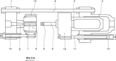
最初に、本発明の押出プレスの概要について図1を用いて説明する。
図1に示すように、本発明に用いる押出プレスはエンドプラテン1とメインシリンダ2を対向して配置し、両者を複数のタイロッド9によって連結している。エンドプラテン1の内側面には押出穴が形成されたダイス4を挟んでコンテナ8が配置され、コンテナ8内にビレット7を装填し、これをダイス4に向けて押出加圧することでダイス穴に応じた断面の押出材が押出成形される。
First, the outline of the extrusion press of the present invention will be described with reference to FIG.
As shown in FIG. 1, in an extrusion press used in the present invention, an
押出作用力を発生させるメインシリンダ2は、メインラム3を内蔵し、これをコンテナ8に向けて加圧移動可能としている。このメインラム3の前端部にはコンテナ8のビレット装填穴と同芯配置されるように押出ステム6がその先端にフィックスダミーブロック5を密接させて、コンテナ8に向けて突出状態でメインクロスヘッド12を介して取付けられている。したがって、メインシリンダ2を駆動してメインクロスヘッド12を前進させると、押出ステム6がコンテナ8のビレット装填穴に挿入され、装填されたビレット7の後端面を加圧して押出材を押出すのである。
The main cylinder 2 that generates the push-out force includes a main ram 3 that can be pressurized and moved toward the
なお、前記メインシリンダ2には押出軸心と平行に複数のサイドシリンダ10が取付けられており、そのシリンダロッド11がメインクロスヘッド12に連結されている。これによって押出工程の準備工程として押出ステム6をコンテナ8に近接させた位置に初期移動させ、押出加圧動作はメインシリンダ2及びサイドシリンダ10の両者を用いて行なわせる構成となっている。
A plurality of
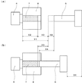
図2、図3、図4は、ダイス4、コンテナ8、ビレット7、フィックスダミーブロック5、押出ステム6の位置関係を拡大して表現したものである。ダイス4にはコンテナ8がコンテナシリンダ14により圧接されている。ビレット7はコンテナ8内に装填されている。
2, 3, and 4 are enlarged representations of the positional relationship between the
図2は本発明のフィックスダミーブロック5が正常に押出ステム6に接合した時の模式図である。
図2(a)は、メインラム3が後退限に位置した状態の模式図である。
ビレット7がコンテナ8の中に装填されて、メインラム3が後退限にある時の状態である。メインラム3が後退限にある時、あるいはメインラム3が前進する時には、押出ステム6とフィックスダミーブロック5は一体であるから、同じ状態になっている。
この状態の時
フィックスダミーブロック5端面からダイス4端面までの距離をX1、
ビレット7長さをX2、
フィックスダミーブロック5がビレット7に当たるまでの距離をX3とすると、
X1=X2+X3の関係式が成り立つ。
また、フィックスダミーブロック5の長さをX8とした。
FIG. 2 is a schematic view when the fixed
FIG. 2A is a schematic diagram of the state where the main ram 3 is positioned at the retreat limit.
This is a state when the
In this state, the distance from the end face of the fixed
If the distance until the fixed
The relational expression X1 = X2 + X3 holds.
The length of the fixed
図2(b)は、メインラム3が前進してフィックスダミーブロック5がビレット7に圧着した状態の模式図である。
図2(a)の状態から、メインラム3または押出ステム6が前進を開始して、フィックスダミーブロック5がコンテナ8内でビレット7と正常に圧接した時の状態である。
この状態の時、メインラム3の後退限からの現在のメインラム3の位置までの距離をX4とすると、
X4=X3=X1−X2
の関係が成り立つ。
FIG. 2B is a schematic view showing a state in which the main ram 3 moves forward and the fixed
The main ram 3 or the
In this state, if the distance from the backward limit of the main ram 3 to the current main ram 3 position is X4,
X4 = X3 = X1-X2
The relationship holds.
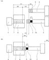
図3は本発明のフィックスダミーブロック5が脱落した時の模式図である。
本発明のフィックスダミーブロック5が脱落する場合は、フィックスダミーブロック5がバイオネットタイプ(フィックスダミーブロック5に花びら状の突起がついていて、その突起を押出ステム6端面の穴に挿入して、ねじった後ピンを差し込んだ状態のタイプ)のものである。また、フィックスダミーブロック5を押出ステム6に装着し忘れた場合のことも本発明の対象になる。
図3(a)は、メインラム3が後退限に位置した状態の模式図である。フィックスダミーブロック5が脱落しているので、押出ステム6がむき出しの状態になっている。
また、図3(a)はメインラム3が後退限に位置した状態であるので、この図の場合、フィックスダミーブロック5が脱落しているので、メインラム3が移動できる範囲はX3とX8を加えたものである。フィックスダミーブロック5が正常に押出ステムに接合した時よりもストロークがX8だけ長くなる。
FIG. 3 is a schematic view when the fixed
When the fixed
FIG. 3A is a schematic diagram of the state where the main ram 3 is located at the backward limit. Since the fixed
3A shows a state in which the main ram 3 is located at the retreat limit. In this case, since the fixed
図3(b)は、メインラム3が前進して押出ステム6がX4の距離だけ前進した状態の模式図である。
メインラム3の後退限で、
フィックスダミーブロック5端面からダイス4端面までの距離をX1、
ビレット長さをX2、
フィックスダミーブロック5がビレット7に当たるまでの距離をX3とすると、
X3=X1−X2となり、
メインラム3の後退限からの現在のメインラム3の位置までの距離をX4とすると、
メインラム3が前進している動作中に
X3<X4
の条件を満たす位置を検出したとき、フィックスダミーブロック5が脱落したと判定するようにした、押出プレスの制御方法。
FIG. 3B is a schematic view showing a state in which the main ram 3 moves forward and the
At the retreat limit of main ram 3,
The distance from the end face of the fixed
Billet length is X2,
If the distance until the fixed
X3 = X1-X2
If the distance from the retreat limit of the main ram 3 to the current main ram 3 position is X4,
While the main ram 3 is moving forward, X3 <X4
A method for controlling an extrusion press in which it is determined that the fixed
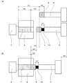
図4は本発明のフィックスダミーブロック5の接合ねじ15が緩んだ時の模式図である。
本発明のフィックスダミーブロック5の接合ねじ15が緩んだ場合は、フィックスダミーブロック5が押出ステム6側に装着されている接合ねじ15によって押出ステム6に装着されている場合である。
図4(a)は、メインラム3が後退限に位置した状態の模式図である。フィックスダミーブロック5の接合ねじがX7ほど緩んでいるので、正常な状態と比べて、フィックスダミーブロック5はX7ほど前に出ている。
図4(a)は、メインラム3が後退限に位置した状態である。この図の場合、フィックスダミーブロック5の接合ねじが緩んでいるので、メインラム3が移動できる範囲はX3とX7を加えたものである。フィックスダミーブロック5が正常に押出ステム6に接合した時よりもストロークがX7だけ短くなる。
FIG. 4 is a schematic view when the joining
The case where the joining
FIG. 4A is a schematic diagram of the state where the main ram 3 is positioned at the retreat limit. Since the fixing screw of the fixed
FIG. 4A shows a state where the main ram 3 is positioned at the backward limit. In the case of this figure, since the joining screw of the fixed
メインラム3の後退限で、
フィックスダミーブロック5端面からダイス4端面までの距離をX1、
ビレット長さをX2、
フィックスダミーブロック5がビレット7に当たるまでの距離をX3とすると、
X3=X1−X2となり、
メインラム3の後退限からの現在のメインラム3の位置までの距離をX4とすると、
フィックスダミーブロック5がビレット7に接触する時点で、
X3>X4
の条件を満たすとき、フィックスダミーブロック5と押出ステム6との接合ねじ15が緩んでいると判定するようにした、押出プレスの制御方法。
なお、この条件を検出する位置は、フィックスダミーブロック5がビレット7に接触する時点でサイドシリンダ10の油圧の圧力が上昇した時の位置である。
At the retreat limit of main ram 3,
The distance from the end face of the fixed
Billet length is X2,
If the distance until the fixed
X3 = X1-X2
If the distance from the retreat limit of the main ram 3 to the current main ram 3 position is X4,
When the fixed
X3> X4
When the above condition is satisfied, it is determined that the joining
The position where this condition is detected is the position when the hydraulic pressure of the
図5(b)は本発明のフィックスダミーブロック5の接合ねじが緩んだ時の模式図に誤差吸収幅を記入した図である
誤差吸収幅とは
1)ビレット7長さの測定誤差
2)ビレット7端面からの測定誤差
3)計測システムに含まれる測定誤差
4)ビレット7の変形による測定誤差
などを含む誤差が最大5mm程度となるが、この誤差による誤検知が生じないようにするための値である。
FIG. 5B is a diagram in which the error absorption width is entered in the schematic diagram when the joining screw of the fixed
図5(b)は、本発明のフィックスダミーブロック5の接合ねじ15が緩んでいる状態の模式図に誤差吸収幅を記入したものである。
フィックスダミーブロック5の接合ねじ15の緩みは、接合ねじ15の長さ70mm程度まで考えられるが、接合ねじ15の緩みは、フィックスダミーブロック5の芯のずれに繋がること、ディスカードの長さが変動することから、誤差吸収幅は出来るだけ小さい値としたいため、最大誤差5mm程度より少し大きい7〜10mm程度とする。
また、誤差吸収幅はフィッスクダミーブロックが緩んで隙間が生じるから早く当たるほうに誤差吸収幅が加算される。
誤差吸収幅は図5(b)のように加算されるので、フィックスダミーブロック5がビレット7に接触する時点では、
X3−X6>X4
が成立する時に、フィックスダミーブロック5の接合ねじ15の緩みがあると判定される、押出プレスの制御方法。
なお、バイオネットタイプの場合も誤差吸収幅の加算によるフィックスダミーブロック5の脱落の判定もできる。
FIG. 5B is a schematic diagram in which the error absorbing width is entered in a state where the joining
The looseness of the joining
In addition, the error absorption width is added to the error absorption width that hits earlier because the fisk dummy block is loosened and a gap is formed.
Since the error absorption width is added as shown in FIG. 5B, when the fixed
X3-X6> X4
A control method of an extrusion press in which it is determined that the joining
In the case of the bayonet type, it is possible to determine whether the fixed
1)従来の様な光電センサーを使わなくても、精度良くフィックスダミーブロックの脱落が検知できるようになり、安定した生産が行われるようになる。
2)フィックスダミーブロックが押出ステムとの接合ねじが緩んでいることも検知できるようになる。
3)従来の様な光電センサーと併用することにより、より確実にフィックスダミーブロックの脱落が検知できるようになる。
1) Even without using a photoelectric sensor as in the prior art, it becomes possible to detect the dropping of the fixed dummy block with high accuracy, and stable production can be performed.
2) It becomes possible to detect that the fixed dummy block has a loose joint screw with the extrusion stem.
3) By using in combination with a conventional photoelectric sensor, it is possible to detect the dropping of the fixed dummy block more reliably.
1 エンドプラテン
2 メインシリンダ
3 メインラム
4 ダイス
5 フィックスダミーブロック
6 押出ステム
7 ビレット
8 コンテナ
9 タイロッド
10 サイドシリンダ
11 サイドシリンダロッド
12 メインクロスヘッド
13 コンテナホルダー
14 コンテナシリンダ
15 接合ねじ
DESCRIPTION OF
15 Joining screw
Claims (3)
メインラムの後退限で、
フィックスダミーブロック端面からダイス端面までの距離をX1、
ビレット長さをX2、
フィックスダミーブロックがビレットに当たるまでの距離をX3とすると、
X3=X1−X2となり、
メインラムの後退限からの現在のメインラムの位置までの距離をX4とすると、
メインラムが前進している動作中に、
X3<X4
の条件を満たす位置を検出したとき、フィックスダミーブロックが脱落したと判定することを特徴とする押出プレスの制御方法。 In the control method of the extrusion press,
At the end of the main ram,
The distance from the end face of the fixed dummy block to the end face of the die is X1,
Billet length is X2,
If the distance until the fixed dummy block hits the billet is X3,
X3 = X1-X2
If the distance from the main ram retreat limit to the current main ram position is X4,
While the main ram is moving forward,
X3 <X4
When the position which satisfy | fills these conditions is detected, it determines with the fixed dummy block having fallen, The control method of the extrusion press characterized by the above-mentioned.
メインラムの後退限で、
フィックスダミーブロック端面からダイス端面までの距離をX1、
ビレット長さをX2、
フィックスダミーブロックがビレットに当たるまでの距離をX3とすると、
X3=X1−X2となり、
メインラムの後退限からの現在のメインラムの位置までの距離をX4とすると、
フィックスダミーブロックがビレットに接触する時点で、
X3>X4
の条件を満たすとき、フィックスダミーブロックと押出ステムとの接合ねじが緩んでいると判定することを特徴とする押出プレスの制御方法。 In the control method of the extrusion press,
At the end of the main ram,
The distance from the end face of the fixed dummy block to the end face of the die is X1,
Billet length is X2,
If the distance until the fixed dummy block hits the billet is X3,
X3 = X1-X2
If the distance from the main ram retreat limit to the current main ram position is X4,
When the fixed dummy block contacts the billet,
X3> X4
When the above condition is satisfied, it is determined that the joining screw between the fixed dummy block and the extrusion stem is loosened.
フィックスダミーブロックがビレットに接触する時点で、
X3−X6>X4
の条件を満たすとき、フィックスダミーブロックと押出ステムとの接合ねじが緩んでいると判定することを特徴とする請求項2に記載の押出プレスの制御方法。
If the error absorption width is X6,
When the fixed dummy block contacts the billet,
X3-X6> X4
3. The method of controlling an extrusion press according to claim 2, wherein when the condition is satisfied, it is determined that the joining screw between the fixed dummy block and the extrusion stem is loose.
Priority Applications (1)
| Application Number | Priority Date | Filing Date | Title |
|---|---|---|---|
| JP2015120855A JP6582585B2 (en) | 2015-06-16 | 2015-06-16 | Extrusion press control method |
Applications Claiming Priority (1)
| Application Number | Priority Date | Filing Date | Title |
|---|---|---|---|
| JP2015120855A JP6582585B2 (en) | 2015-06-16 | 2015-06-16 | Extrusion press control method |
Publications (2)
| Publication Number | Publication Date |
|---|---|
| JP2017001087A true JP2017001087A (en) | 2017-01-05 |
| JP6582585B2 JP6582585B2 (en) | 2019-10-02 |
Family
ID=57750962
Family Applications (1)
| Application Number | Title | Priority Date | Filing Date |
|---|---|---|---|
| JP2015120855A Active JP6582585B2 (en) | 2015-06-16 | 2015-06-16 | Extrusion press control method |
Country Status (1)
| Country | Link |
|---|---|
| JP (1) | JP6582585B2 (en) |
Citations (2)
| Publication number | Priority date | Publication date | Assignee | Title |
|---|---|---|---|---|
| JPH03120910U (en) * | 1990-03-20 | 1991-12-11 | ||
| JPH08168816A (en) * | 1994-12-16 | 1996-07-02 | Ube Ind Ltd | Method for preventing falling of fixed dummy block |
-
2015
- 2015-06-16 JP JP2015120855A patent/JP6582585B2/en active Active
Patent Citations (2)
| Publication number | Priority date | Publication date | Assignee | Title |
|---|---|---|---|---|
| JPH03120910U (en) * | 1990-03-20 | 1991-12-11 | ||
| JPH08168816A (en) * | 1994-12-16 | 1996-07-02 | Ube Ind Ltd | Method for preventing falling of fixed dummy block |
Also Published As
| Publication number | Publication date |
|---|---|
| JP6582585B2 (en) | 2019-10-02 |
Similar Documents
| Publication | Publication Date | Title |
|---|---|---|
| TWI380859B (en) | Stem sliding apparatus | |
| JP6582585B2 (en) | Extrusion press control method | |
| US20150298189A1 (en) | Extrusion die using shock-absorbing pad and method for manufacturing extrusion | |
| KR101906088B1 (en) | Direct or indirect metal pipe extrusion process, mandrel for extruding metal pipes, metal pipe extruder and extruded metal pipe | |
| JP6612600B2 (en) | Manufacturing method by cold forging of cylindrical metal fittings with polygonal flanges | |
| CN109975147B (en) | Loss detection method and loss detection system for linear actuator | |
| JP5834643B2 (en) | Extrusion press and extrusion press control method | |
| US10898943B2 (en) | Self-piercing rivet device and method of operating a self-piercing rivet device to inhibit incorrect die usage | |
| JP6131941B2 (en) | Pressure sensor mounting structure and pressure sensor position adjusting method | |
| KR100904871B1 (en) | Tip testing method | |
| JP4391491B2 (en) | Pressing device for tunnel core punching pin and casting method using tunnel core punching pin pressurizing device | |
| CN109047439A (en) | Thin-wall workpiece side wall gets tooling ready | |
| JP7308054B2 (en) | die casting machine | |
| JP6613913B2 (en) | Degassing control method of extrusion press | |
| JP2012035292A (en) | Forging mold of rod-like workpiece and method for forging the rod-like workpiece | |
| US4252174A (en) | Method and apparatus for monitoring the operation of a reciprocating liquid injection unit | |
| JP2020138209A (en) | Die casting device | |
| JP6455840B2 (en) | Squeeze pin operation determination device and squeeze pin operation determination method | |
| WO2016185521A1 (en) | Method for extracting high viscosity substance and device for extracting high viscosity substance | |
| JP2010012490A (en) | Injection cylinder capability measuring apparatus | |
| JP6003841B2 (en) | UOE steel pipe peaking reduction method | |
| JP6642613B2 (en) | End platen for extrusion press equipment | |
| JP2000334515A (en) | Extruding machine | |
| JP4148874B2 (en) | Method and apparatus for determining the presence or absence of galling in a press-fitting process | |
| JP4050285B2 (en) | Method for injecting molten metal material in molten metal material injection apparatus |
Legal Events
| Date | Code | Title | Description |
|---|---|---|---|
| A621 | Written request for application examination |
Free format text: JAPANESE INTERMEDIATE CODE: A621 Effective date: 20180413 |
|
| A977 | Report on retrieval |
Free format text: JAPANESE INTERMEDIATE CODE: A971007 Effective date: 20190212 |
|
| A131 | Notification of reasons for refusal |
Free format text: JAPANESE INTERMEDIATE CODE: A131 Effective date: 20190219 |
|
| A521 | Request for written amendment filed |
Free format text: JAPANESE INTERMEDIATE CODE: A523 Effective date: 20190404 |
|
| TRDD | Decision of grant or rejection written | ||
| A01 | Written decision to grant a patent or to grant a registration (utility model) |
Free format text: JAPANESE INTERMEDIATE CODE: A01 Effective date: 20190806 |
|
| A61 | First payment of annual fees (during grant procedure) |
Free format text: JAPANESE INTERMEDIATE CODE: A61 Effective date: 20190819 |
|
| R150 | Certificate of patent or registration of utility model |
Ref document number: 6582585 Country of ref document: JP Free format text: JAPANESE INTERMEDIATE CODE: R150 |
|
| S533 | Written request for registration of change of name |
Free format text: JAPANESE INTERMEDIATE CODE: R313533 |
|
| R350 | Written notification of registration of transfer |
Free format text: JAPANESE INTERMEDIATE CODE: R350 |
|
| R250 | Receipt of annual fees |
Free format text: JAPANESE INTERMEDIATE CODE: R250 |
|
| R250 | Receipt of annual fees |
Free format text: JAPANESE INTERMEDIATE CODE: R250 |
|
| R250 | Receipt of annual fees |
Free format text: JAPANESE INTERMEDIATE CODE: R250 |