JP2016534843A - System and method for minimizing fiber twist in optical shape sensing enabled devices - Google Patents
System and method for minimizing fiber twist in optical shape sensing enabled devices Download PDFInfo
- Publication number
- JP2016534843A JP2016534843A JP2016545073A JP2016545073A JP2016534843A JP 2016534843 A JP2016534843 A JP 2016534843A JP 2016545073 A JP2016545073 A JP 2016545073A JP 2016545073 A JP2016545073 A JP 2016545073A JP 2016534843 A JP2016534843 A JP 2016534843A
- Authority
- JP
- Japan
- Prior art keywords
- twist
- optical fiber
- fiber
- optical
- shape sensing
- Prior art date
- Legal status (The legal status is an assumption and is not a legal conclusion. Google has not performed a legal analysis and makes no representation as to the accuracy of the status listed.)
- Pending
Links
Images


Classifications
-
- A—HUMAN NECESSITIES
- A61—MEDICAL OR VETERINARY SCIENCE; HYGIENE
- A61B—DIAGNOSIS; SURGERY; IDENTIFICATION
- A61B90/00—Instruments, implements or accessories specially adapted for surgery or diagnosis and not covered by any of the groups A61B1/00 - A61B50/00, e.g. for luxation treatment or for protecting wound edges
- A61B90/36—Image-producing devices or illumination devices not otherwise provided for
-
- A—HUMAN NECESSITIES
- A61—MEDICAL OR VETERINARY SCIENCE; HYGIENE
- A61B—DIAGNOSIS; SURGERY; IDENTIFICATION
- A61B34/00—Computer-aided surgery; Manipulators or robots specially adapted for use in surgery
- A61B34/20—Surgical navigation systems; Devices for tracking or guiding surgical instruments, e.g. for frameless stereotaxis
-
- G—PHYSICS
- G01—MEASURING; TESTING
- G01B—MEASURING LENGTH, THICKNESS OR SIMILAR LINEAR DIMENSIONS; MEASURING ANGLES; MEASURING AREAS; MEASURING IRREGULARITIES OF SURFACES OR CONTOURS
- G01B11/00—Measuring arrangements characterised by the use of optical techniques
- G01B11/24—Measuring arrangements characterised by the use of optical techniques for measuring contours or curvatures
-
- G—PHYSICS
- G02—OPTICS
- G02B—OPTICAL ELEMENTS, SYSTEMS OR APPARATUS
- G02B6/00—Light guides; Structural details of arrangements comprising light guides and other optical elements, e.g. couplings
- G02B6/24—Coupling light guides
- G02B6/36—Mechanical coupling means
-
- A—HUMAN NECESSITIES
- A61—MEDICAL OR VETERINARY SCIENCE; HYGIENE
- A61B—DIAGNOSIS; SURGERY; IDENTIFICATION
- A61B34/00—Computer-aided surgery; Manipulators or robots specially adapted for use in surgery
- A61B34/20—Surgical navigation systems; Devices for tracking or guiding surgical instruments, e.g. for frameless stereotaxis
- A61B2034/2046—Tracking techniques
- A61B2034/2061—Tracking techniques using shape-sensors, e.g. fiber shape sensors with Bragg gratings
Landscapes
- Health & Medical Sciences (AREA)
- Surgery (AREA)
- Life Sciences & Earth Sciences (AREA)
- Physics & Mathematics (AREA)
- Engineering & Computer Science (AREA)
- General Health & Medical Sciences (AREA)
- Animal Behavior & Ethology (AREA)
- Veterinary Medicine (AREA)
- Nuclear Medicine, Radiotherapy & Molecular Imaging (AREA)
- Public Health (AREA)
- Biomedical Technology (AREA)
- Heart & Thoracic Surgery (AREA)
- Medical Informatics (AREA)
- Molecular Biology (AREA)
- General Physics & Mathematics (AREA)
- Pathology (AREA)
- Oral & Maxillofacial Surgery (AREA)
- Optics & Photonics (AREA)
- Robotics (AREA)
- Endoscopes (AREA)
- Length Measuring Devices By Optical Means (AREA)
Abstract
光学形状センシング可能な器具のためのファイバねじれ現象システムは、光ファイバ(28)を保持するように構成される回転可能な送出固定具(12)を含む。光学形状センシング使用可能デバイス(26)は、そこに配置される光ファイバを含む。回転機構(14)が、その長さに沿って蓄積されるねじれを減少させるためにファイバのねじれに応じてファイバを回転させるように構成される。A fiber twisting system for an optical shape sensing instrument includes a rotatable delivery fixture (12) configured to hold an optical fiber (28). The optical shape sensing enabled device (26) includes an optical fiber disposed therein. A rotating mechanism (14) is configured to rotate the fiber in response to the twist of the fiber to reduce the twist that accumulates along its length.
Description
この開示は、医療器具、より具体的には医療応用における形状センシング光ファイバのねじれを減少させるためのものに関する。 This disclosure relates to medical devices, and more particularly to reducing twisting of shape sensing optical fibers in medical applications.
ファイバ光学に基づく形状センシングは、従来の光ファイバにおける固有の後方散乱を利用する。使用される原理は、例えば、標準的なシングルモード通信ファイバにおいて特徴的なレイリーパターンでの光ファイバのひずみ分布測定である。レイリー散乱は、ファイバコアの屈折率のランダム変動の結果として生じる。これらのランダム変動は、長さに沿った振幅及び位相のランダム変動でモデル化されることができる。ファイバブラッググレーティングもまた用いられ得る。マルチコアファイバの単一の長さの中に延びる3以上のコアにおけるこれらの効果を利用することによって、関心のある表面の3次元(3D)形状及び動態(dynamics)が再構成されることができる。 Shape sensing based on fiber optics takes advantage of the inherent backscatter in conventional optical fibers. The principle used is, for example, the measurement of the strain distribution of an optical fiber with a Rayleigh pattern characteristic in standard single-mode communication fibers. Rayleigh scattering occurs as a result of random fluctuations in the refractive index of the fiber core. These random variations can be modeled with random variations in amplitude and phase along the length. Fiber Bragg gratings can also be used. By taking advantage of these effects in more than two cores extending into a single length of a multi-core fiber, the three-dimensional (3D) shape and dynamics of the surface of interest can be reconstructed. .
1つのコアが断面の中心に位置している4以上のコアファイバシステムでは、軸方向ひずみ(張力)が加えられない限り、又は張力が既知であり且つ制御可能である(又は較正されることができる)場合、曲げ及び温度効果に起因するひずみを分離することができる。参照ファイルは、中心コアの周りの外側コアの巻きの割合の値(ウォブルとも呼ばれる)を保管するが、過度なねじれがあるとき、ウォブルの変化の率は非線形な率で増加するので、この効果を区別することがより困難になる。これは、しばしば、ファイバ長手方向軸周りの2πねじれを超える不正確及び6πねじれを超える不安定につながる。 In a four or more core fiber system where one core is located in the center of the cross-section, the tension is known and controllable (or calibrated) unless axial strain (tension) is applied. If possible, strains due to bending and temperature effects can be isolated. The reference file stores the value of the outer core winding ratio (also called wobble) around the central core, but this effect is because when there is excessive twist, the rate of wobble change increases at a non-linear rate. It becomes more difficult to distinguish. This often leads to inaccuracy exceeding 2π twist about the fiber longitudinal axis and instability exceeding 6π twist.
ファイバに固定先端光学形状センシング(OSS)使用可能デバイスを組み込むことは、ファイバの送出領域(launch region)を送出固定具(launch fixture)の中に、及びファイバの先端を器具の遠位先端に固定することを含む。送出固定具が手術台又は他の構造に強固に取り付けられていることを仮定すると、これらの2つの固定点は、介入中に器具がトルクを加えられるとき、ファイバの長さに沿ったねじれの蓄積をもたらす。このねじれ値の知識は、器具のロール自由度を測定するために使用される。しかし、OSSファイバは、いずれかの方向のその軸回りの約2πのねじれまでしか正確な形状再構成を生じさせることができず、6πの累積的なねじれの近くで安定性を失う。 Incorporating a fixed tip optical shape sensing (OSS) enabled device into the fiber secures the fiber launch region into the launch fixture and the fiber tip to the distal tip of the instrument. Including doing. Assuming that the delivery fixture is firmly attached to the operating table or other structure, these two fixation points are not twisted along the length of the fiber when the instrument is torqued during the intervention. Cause accumulation. This knowledge of the twist value is used to measure the roll degree of freedom of the instrument. However, OSS fibers can only produce accurate shape reconstructions up to about 2π twist about their axis in either direction, and lose stability near a cumulative twist of 6π.
ねじれは、操作中にオペレータが器具を回転させることによって、又は器具が動かされるときのファイバと器具管腔との間の摩擦(スティック−スリップ)によって、導入され得る。臨床使用の間、特に、脈管手術では、医者はしばしば、複数のπ回転を通してガイドワイヤ/器具を回転させる(又は「トルクを与える」)。このようなトルクを与えることは、固定先端デバイスにおけるねじれの蓄積につながり、これはデバイスの配向を測定するために必要であるが、形状センシングの精度を、さらにまた安定性を失わせ、最終的に、形状再構成の崩壊を引き起こす。この限界は、それが医者に制限を加えるので、固定先端OSSデバイスの臨床ユーザビリティに深刻に影響を与える。したがって、器具の配向が依然として既知であるとともに、器具が通常の方法で操作され且つトルクを与えられることができながら、医者によってファイバに加えられるねじれの量を最小にすることが必須である。 Twist can be introduced by the operator rotating the instrument during operation or by friction (stick-slip) between the fiber and the instrument lumen as the instrument is moved. During clinical use, particularly in vascular surgery, doctors often rotate (or “torque”) the guidewire / instrument through multiple π rotations. Giving such torque leads to the accumulation of torsion in the fixed tip device, which is necessary to measure the orientation of the device, but also reduces the accuracy of shape sensing, and also loses stability and ultimately In addition, it causes collapse of shape reconstruction. This limitation seriously affects the clinical usability of fixed tip OSS devices as it places a limitation on the physician. Therefore, it is essential to minimize the amount of twist applied to the fiber by the physician while the orientation of the instrument is still known and the instrument can be manipulated and torqued in the normal manner.
本原理によれば、光学形状センシング可能な器具のためのファイバねじれ減少システムは、光ファイバを保持するように構成される回転可能な送出固定具を含む。光学形状センシング使用可能デバイスは、その中に配置された光ファイバを含む。回転機構が、ファイバの長さに沿って蓄積されるねじれを減少させるようにファイバのねじれに応じてファイバを回転させるように構成される。 In accordance with the present principles, a fiber twist reduction system for an optical shape sensing instrument includes a rotatable delivery fixture configured to hold an optical fiber. The optical shape sensing enabled device includes an optical fiber disposed therein. A rotation mechanism is configured to rotate the fiber in response to the twist of the fiber so as to reduce the twist that accumulates along the length of the fiber.
光学形状センシング可能な器具のためのファイバねじれ減少システムは、その中に配置された少なくとも1つの光ファイバを有する光学形状センシング使用可能デバイスを含む。回転可能な送出固定具が、少なくとも1つの光ファイバを保持するように構成され、回転機構が、少なくとも1つの光ファイバの送出領域を回転させるように構成される。コントローラが、回転機構に結合され、少なくとも1つの光ファイバのねじれに応じて回転機構が少なくとも1つの光ファイバの中の蓄積されるねじれを少なくとも減少させることを可能にするように構成される。 A fiber twist reduction system for an optical shape sensing instrument includes an optical shape sensing enabled device having at least one optical fiber disposed therein. A rotatable delivery fixture is configured to hold at least one optical fiber, and a rotation mechanism is configured to rotate the delivery region of the at least one optical fiber. A controller is coupled to the rotation mechanism and is configured to allow the rotation mechanism to at least reduce accumulated twist in the at least one optical fiber in response to the twist of the at least one optical fiber.
形状センシング使用可能デバイスのための光ファイバの蓄積されるねじれを減少させるための方法が、少なくとの1つの光ファイバを保持するように構成されている回転可能なファイバ送出固定具、その中に配置された少なくとも1つの光ファイバを含む光学形状センシング使用可能デバイス、及び回転可能なファイバ送出固定具に配置された光ファイバを回転させるように構成される回転機構を提供すること;光学形状センシング使用可能デバイスの中に配置された少なくとも1つの光ファイバのねじれを測定すること;並びにねじれに応じて、少なくとも1つの光ファイバの中の蓄積されるねじれを少なくとも減少させるように回転機構を使用してファイバ送出固定具を回転させることを含む。 A method for reducing the accumulated twist of an optical fiber for a shape sensing enabled device includes a rotatable fiber delivery fixture configured therein to hold at least one optical fiber therein An optical shape sensing enabled device comprising at least one optical fiber disposed, and a rotation mechanism configured to rotate the optical fiber disposed in a rotatable fiber delivery fixture; using optical shape sensing Measuring the twist of at least one optical fiber disposed in the enabled device; and using a rotating mechanism to at least reduce the accumulated twist in the at least one optical fiber in response to the twist Rotating the fiber delivery fixture.
本開示のこれらの及び他の特徴並びに利点は、説明することを意図し且つ開示を限定することを意図しない添付の図面とともに、本開示の特定の実施形態の以下の記載からより完全に理解されるであろう。 These and other features and advantages of the present disclosure will be more fully understood from the following description of specific embodiments of the present disclosure, together with the accompanying drawings, which are intended to illustrate and not to limit the disclosure. It will be.
本開示は、以下の図面を参照して好適な実施形態の以下の説明を詳細に提供する。
本原理にしたがって、例えば、1自由度作動送出固定具を使用する、光学形状センシング(OSS)デバイスのねじれを測定し且つ考慮する装置及び方法が提供される。固定具は、ファイバの長さに沿って蓄積されるねじれを最小にするようにOSSファイバの送出領域を操る。1つの実施形態では、装置は、モータ、エンコーダ、モータコントローラ及びファイバの軸に沿った送出領域を回転させるのに適した機構を含む。ねじれは、ねじれの蓄積がファイバで観測されるとき、モータがねじれ値をゼロに駆動するように送出領域を回転させるように、ファイバからのねじれ信号でモータ制御ループを閉じることによって最小にされる。 In accordance with the present principles, an apparatus and method is provided for measuring and accounting for torsion of optical shape sensing (OSS) devices, for example using a one degree of freedom actuated delivery fixture. The fixture manipulates the delivery area of the OSS fiber to minimize the twist that accumulates along the length of the fiber. In one embodiment, the apparatus includes a motor, an encoder, a motor controller, and a mechanism suitable for rotating the delivery region along the fiber axis. Twist is minimized by closing the motor control loop with a twist signal from the fiber so that when the twist buildup is observed in the fiber, the motor rotates the delivery region to drive the twist value to zero. .
この回転は、ファイバ再構成の座標系も事実上変化させる(例えば、ファイバのz軸回りの、すなわちその長手方向軸に沿った、回転を引き起こす)ので、エンコーダが、ファイバの形状及び配向が正しい座標系内で正確に再構成されることができるように、送出領域が被る絶対角変位を測定するために必要とされる。1自由度(1DoF)機構が、固定先端デバイスのねじれ蓄積を最小化するために作動される一方、測定されることになるデバイスの回転自由度も可能にする。ファイバの送出/近位セグメントを要望通りにねじれを最小化する方法で動かすロボット又はメカトロニクス機構が、用いられ得る。 This rotation also effectively changes the coordinate system of the fiber reconstruction (eg, causing rotation around the z-axis of the fiber, ie, along its longitudinal axis) so that the encoder is correct for the fiber shape and orientation. It is required to measure the absolute angular displacement experienced by the delivery area so that it can be accurately reconstructed in the coordinate system. While a one degree of freedom (1 DoF) mechanism is actuated to minimize the torsional accumulation of the fixed tip device, it also allows the rotational freedom of the device to be measured. A robot or mechatronic mechanism can be used that moves the fiber delivery / proximal segment in a manner that minimizes twist as desired.
したがって、本原理は、器具の配向が依然として既知であることを確実にしながら、医者によってファイバに加えられるねじれの量を最小化する。器具は、依然として医者によって通常の方法で操作される及びトルクを加えられることができる。様々な実施形態が、ねじれを最小にする方法でファイバの送出/近位セグメントを動かすロボット/メカトロニクス機構を含み得る。 Thus, this principle minimizes the amount of twist applied to the fiber by the physician while ensuring that the orientation of the instrument is still known. The instrument can still be manipulated and torqued in the usual way by a physician. Various embodiments may include a robot / mechatronic mechanism that moves the delivery / proximal segment of the fiber in a manner that minimizes twist.
本発明が、医療器具の観点から記載されているが、本発明の教示は、はるかに広く且つ任意の光ファイバ器具に適用可能であることも理解されるべきである。幾つかの実施形態では、本原理は、複雑な生物又は機械システムを追跡又は解析するのに用いられる。特に、本原理は、生物学的システムの内部の追跡手段、肺、消化管、排泄器官、血管等のような体の全領域における手術に適用可能である。図面に描かれる要素は、ハードウェア及びソフトウェアの様々な組み合わせで実装され得るとともに、1つの要素又は多数の要素の中に組み合わされ得る機能を提供し得る。 Although the present invention has been described in terms of medical devices, it should also be understood that the teachings of the present invention are much broader and are applicable to any fiber optic device. In some embodiments, the present principles are used to track or analyze complex biological or mechanical systems. In particular, the present principles are applicable to surgery in all areas of the body such as tracking means inside the biological system, lungs, gastrointestinal tract, excretory organs, blood vessels and the like. The elements depicted in the drawings can be implemented in various combinations of hardware and software and can provide functionality that can be combined into one element or multiple elements.
図面に示された様々な要素の機能は、専用ハードウェア並びに適切なソフトウェアとの関連でソフトウェアを実行することができるハードウェアの使用を通じて提供されることができる。プロセッサによって提供されるとき、機能は、1つの専用プロセッサによって、1つの共有プロセッサによって、又はその幾つかが共有されることができる、複数の個別のプロセッサによって、提供されることができる。さらに、用語「プロセッサ」又は「コントローラ」の明示的な使用は、ソフトウェアを実行することができるハードウェアだけを指すように解釈されるべきではなく、制限なしに、デジタルシグナルプロセッサ(“DSP”)ハードウェア、ソフトウェアを記憶するためのリードオンリメモリ(“RAM”)、ランダムアクセスメモリ(“ROM”)、不揮発性記憶装置等を非明示的含むことができる。 The functionality of the various elements shown in the drawings can be provided through the use of dedicated hardware as well as hardware capable of executing software in conjunction with appropriate software. When provided by a processor, the functionality can be provided by one dedicated processor, by one shared processor, or by multiple individual processors, some of which can be shared. Furthermore, the explicit use of the term “processor” or “controller” should not be construed to refer only to hardware capable of executing software, but without limitation, a digital signal processor (“DSP”). Hardware, read only memory (“RAM”) for storing software, random access memory (“ROM”), non-volatile storage, etc. may be implicitly included.
そのうえ、本発明の原理、態様、及び実施形態、並びにその特定の例を列挙する本明細書の全ての記述は、その構造的及び機能的な均等物両方を包含することを意図される。加えて、このような均等物が、現在既知の均等物並びに将来開発される均等物(すなわち、構造にかかわらず、同じ機能を実行する開発される任意の要素)両方を含むことが意図される。したがって、例えば、本明細書に提示されるブロック図が、本発明の原理を具体化する例示的なシステム構成要素及び/又は回路の概念的ビューを示すことが当業者によって理解されるであろう。同様に、任意のフローチャート、フロー図等が、コンピュータ可読記憶媒体で実質的に示されることができそして、このようなコンピュータ又はプロセッサが明示的に示されていようがなかろうが、コンピュータ又はプロセッサによって実行され得る様々なプロセスを示すことが理解されるであろう。 Moreover, all statements herein reciting principles, aspects, and embodiments of the invention, as well as specific examples thereof, are intended to encompass both structural and functional equivalents thereof. In addition, such equivalents are intended to include both currently known equivalents as well as equivalents developed in the future (ie, any element developed that performs the same function, regardless of structure). . Thus, for example, it will be appreciated by those skilled in the art that the block diagrams presented herein illustrate a conceptual view of exemplary system components and / or circuits embodying the principles of the invention. . Similarly, any flowcharts, flow diagrams, etc. may be substantially illustrated on a computer-readable storage medium, and such computers or processors may or may not be explicitly illustrated by a computer or processor. It will be understood that various processes that can be performed are shown.
さらに、本発明の実施形態は、コンピュータ若しくは命令実行システムによる又はコンピュータ若しくは命令実行システムと関連した使用のためのコンピュータプログラムコードを提供するコンピュータ使用可能若しくはコンピュータ可読記憶媒体からアクセス可能なコンピュータプログラムプロダクトの形態を取ることができる。この説明のために、コンピュータ使用可能若しくはコンピュータ可読記憶媒体は、命令実行システム、装置、若しくはデバイスによる又は命令実行システム、装置、若しくはデバイスと関連した使用のためのプログラムを含む、記憶、通信、伝達、又は移送し得る任意の装置であることができる。媒体は、電子的、磁気的、光学的、電磁的、赤外線の、又は半導体システム(又は装置又はデバイス)又は伝搬媒質であることができる。コンピュータ可読媒体の例は、半導体又は固体メモリ、磁気テープ、取り外し可能なコンピュータディスケット、ランダムアクセスメモリ(RAM)、リードオンリメモリ(ROM)、固い磁気ディスク及び光ディスクを含む。光ディスクの現在の例は、コンパクトディスク−リードオンリメモリ(CD−ROM)、コンパクトディスク−リード/ライト(CD−R/W)、Blu−Ray(商標)及びDVDを含む。 Further, embodiments of the present invention provide a computer program product accessible from a computer-usable or computer-readable storage medium that provides computer program code for use by or in connection with a computer or instruction execution system. Can take form. For purposes of this description, a computer usable or computer readable storage medium includes storage, communication, transmission, including a program for use by or in connection with an instruction execution system, apparatus, or device. Or any device that can be transported. The medium can be an electronic, magnetic, optical, electromagnetic, infrared, or semiconductor system (or apparatus or device) or a propagation medium. Examples of computer readable media include semiconductor or solid state memory, magnetic tape, removable computer diskettes, random access memory (RAM), read only memory (ROM), hard magnetic disks and optical disks. Current examples of optical disks include compact disk-read only memory (CD-ROM), compact disk-read / write (CD-R / W), Blu-Ray ™ and DVD.
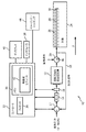
次に、同様の数字が同じ又は同様の要素を示す図面をそして最初に図1を参照すると、光学形状センシング送出システム10が、1つの実施形態にしたがって例示的に示されている。システム10は、回転可能な送出固定具12を含む。回転可能な送出固定具12は、手術台又は他の構造に強固に取り付けられる又は装着されることができ且つ光ファイバ28及び/又は光ファイバ28を含む器具26を定位置に保持するために用いられる1自由度作動コンポーネントを含む。送出固定具は通常は、如何なる回転コンポーネントも有さない。しかし、本原理によれば、回転可能な送出固定具12は、そこに接合又は他の方法で付けられたOSSファイバの送出領域を有する。回転可能な送出固定具12は、OSS器具又は装置26のねじれを最小にするために送出システム10の残りの部分に対して回転する。
Referring now to the drawings wherein like numerals indicate the same or similar elements, and initially to FIG. 1, an optical shape
送出領域は、そこから再構成が始まるファイバ28に沿った長手方向距離(例えば、約20mm)を含む。これは、ファイバ28の(0,0,0)位置を定める。送出領域は、再構成モジュール又はアルゴリズム42が、再構成を初期化するために線形ひずみとともに20mm長さを有するように、提供される。再構成が送出領域から始まるので、送出領域の位置及び配向は、如何なる実行された手術前の登録も有効なままであるように、手術を通じて知られている必要がある。
The delivery region includes a longitudinal distance (eg, about 20 mm) along the
固定具12は、ファイバ28の長さに沿って蓄積されるねじれを最小にするためにOSS使用可能デバイス又は器具26の1つのファイバ又は複数のファイバ28の送出領域を操作する。システム10は、モータ14又は同様の装置、エンコーダ16のような、センシングデバイス、及びモータコントローラ32を含み得る。エラー最小化コンポーネント17が、コントローラ32のためにゼロねじれ位置を参照するために含まれ得るとともに、ファイバ28の送出領域を回転させるのに適する機構又はハンドル20が設けられ得る。
The
回転送出固定具12は、光ファイバ29の送出領域を定位置に固定するための溝又は他の機構を含む。ファイバ28の送出領域は、そこから形状再構成が始まり且つ任意の再構成形状の初期位置及び配向(すなわち、ファイバの(0,0,0)位置)を定めるファイバに沿った場所であるので、送出領域全体が送出固定具12に固定されることが好ましい。
The
ねじれは、ねじれの蓄積がファイバ28で観測されるとき、モータ14が回転可能な送出固定具12を回転させ、したがって、ファイバの送出領域がねじれ値をゼロに駆動するように、ファイバ28又は他のソース(例えば、イメージング及び/又はトラッキングシステム44)からのねじれ信号18でモータ制御ループを閉じることによって、最小にされる。1つの実施形態では、送出固定具12の中の回転可能な要素だけではなく、送出システム10全体が、回転されるようにされ得る。
Twist is the
回転は、ファイバ再構成の座標系も実際上変化させる(すなわち、ファイバのz軸周りの回転を引き起こす)ので、エンコーダ16が、ファイバの形状及び配向が正しい座標系の中で正確に再構成されることができるように、ファイバ送出領域が受けている絶対角変位を測定するために用いられる。OSSファイバ28からのねじれ信号18は、モータコントローラ32に入力される。コントローラ32は、ファイバ28が受けるねじれを最小にするためにファイバ送出領域を回転させるためのフィードバックとしてねじれ信号を用いる。この回転の測定値は次に、メモリ36に記憶されたファイバ再構成アルゴリズム又はモジュール42への入力として使用されることができる。エンコーダ16からのエンコーダ信号が、モータコントローラ32に提供され、座標系が固定具12及びファイバ28の任意の動きにしたがって将来のデータを収集するために更新されることを確実にするように、ファイバ再構成アルゴリズム42に接続されることができる。
Rotation also effectively changes the fiber reconstruction coordinate system (ie, causes rotation about the z-axis of the fiber) so that the
モータコントローラ32は、別個の若しくはスタンドアローンのコントローラを含み得る又はコンピュータシステム若しくはOSSコンソールの一部であり得、これは、ファイバ形状再構成、ユーザ対応プログラミング、ユーザインタフェーシング等のような他の機能を提供することが理解されるべきである。例えば、コントローラ32、システム10及び他の特徴は、そこから手術が監視及び/又は管理されるワークステーション若しくはコンソールの一部であり得る。
The
コントローラ32は、1又は複数のプロセッサ34並びにプログラム及びアプリケーションを記憶するためのメモリ36を含み得る。メモリ36は、ファイバ再構成アルゴリズム又はモジュール42を記憶することができ、このアルゴリズム又はモジュールは、OSS使用可能デバイス26からの光学フィードバック信号を解釈するように構成される。モジュール42は、OSS使用可能デバイスに関連付けられる変形、偏向及び他の変化を再構成するために光学信号フィードバックを使用するように構成され、このOSS使用可能デバイスは医療デバイス又は器具を含み得る。ねじれは、ねじれの蓄積がファイバ28において観測されるとき、モータ14がねじれ値をゼロに駆動するよう送出領域を回転させるように、ファイバ28からのねじれ信号18でモータ制御ループを閉じることによって最小にされる。ねじれ信号18は、OSSコンソール若しくはコントローラ32から処理され得る又はTCP/IP通信チャンネル又はモータがそれを読むたびに上書きされるEEPROM等のような標準的な方法を使用して作動される回転可能な送出固定具12と通信することができる。ファイバ28で生成されるねじれを示す他の信号もまた、これらの又は他のデバイス若しくはモジュールのために用いられ得る。
The
他の実施形態では、ファイバ送出領域の回転は、作動手段よりむしろ受動的な手段によって達成され得る。このような実施形態では、オペレータによって引き起こされる器具26の回転は、回転可能な送出固定具12に機械的に結合される。回転可能な送出固定具12は、ねじれ蓄積を防ぐために、ハンドル20に沿って回転され得る。他の実施形態では、ファイバ28を回転させるための機構は、送出固定具12の中に配置されず、むしろ、器具26の長さに沿ったあるポイントに配置され得る。このような実施形態では、機構は、ハンドル20又は器具26の長さに沿ったハブの中に配置されることができる。
In other embodiments, rotation of the fiber delivery region may be achieved by passive means rather than actuation means. In such an embodiment, the rotation of the
OSS使用可能デバイス26は、カテーテル、ガイドワイヤ、プローブ、内視鏡、ロボット、電極、フィルタデバイス、バルーンデバイス、又は他の医療コンポーネント等を含み得る。OSS使用可能デバイス26は、設定された1つのパターン又は複数のパターンでデバイス26に結合される1又は複数の光ファイバ28を含み得る。光ファイバ28は、回転送出固定具12に接続する。OSS使用可能デバイス26は、例えば、光ファイバブラッググレーティングセンサ、レイリー散乱又は他の散乱を使用して、その形状及び/又は位置が決定され得る。
The OSS enabled
形状画像又は他の出力がディスプレイ40で見られ得る。ディスプレイ40は、対象(患者)又は体積24の内部画像を見るために構成され得るとともにセンシングデバイス26の重ね合わせ又は他のレンダリングとしての画像を含み得る。ディスプレイ40はまた、ユーザが、コントローラ32及びその構成要素及び機能、又はシステム内の任意の他の要素と情報をやりとりすることを可能にし得る。これは、キーボード、マウス、ジョイスティック、触覚デバイス、又は任意の他の周辺機器若しくは制御装置を含み得るインタフェース38によってさらに促進される。
A shape image or other output may be seen on the
本原理によれば、蓄積されるねじれは、ねじれ信号をゼロ又はゼロ近くに保つようにファイバ28の送出領域を回転させることによって、固定先端OSS可能な器具26において最小にされる。他の実施形態では、送出領域は、(全期間の代わりに)継時的なねじれの変化の測定に基づいて回転され得る。この方法では、回転補正が、よりゆるやかに及び/又は制御されて行われることができる。
According to the present principles, accumulated twist is minimized in the fixed tip OSS
送出領域を回転させるための他の方法又は機構が、用いられ得るとともに、異なるOSS使用可能デバイス、回転モータを含む作動機構、エンコーダ、ベアリング、伝達要素、リニアアクチュエータ、モータコントローラ等を含み得る。1つの実施形態では、EEPROMが、OSSファイバパラメータ及びモータ角度及び直線変位を記憶するために使用されることができる。 Other methods or mechanisms for rotating the delivery area can be used and can include different OSS-enabled devices, actuation mechanisms including rotary motors, encoders, bearings, transfer elements, linear actuators, motor controllers, and the like. In one embodiment, an EEPROM can be used to store OSS fiber parameters and motor angle and linear displacement.
他の実施形態では、異なる入力が、OSS又はねじれ信号18が利用可能でない又は使用可能でないとき制御ループを閉じるために使用され得る。OSSねじれデータのための代替信号が、イメージングシステム(カメラ、x線等)及び/又はそれらがデバイス26を操作するときの器具又は医者の手を追跡するトラッキングシステム(赤外線(IR)/光学的/電磁気的(EM))44の使用を含み得る。他の実施形態では、別個の回転エンコーダ46が、ハンドル20(又はハブ、トルク又は送出固定具)の中に含まれることができ、これは、オペレータによって器具に加えられるトルク又はねじれを測定する。さらに他の実施形態では、器具の既知の形状の配向の変化に基づくねじれ計算が用いられ得る。この形状情報は、OSS又は他のイメージングモダリティ(例えば、x線)から得られることができる。これらの代替シナリオでは、オペレータによる近位回転は、遠位先端30での蓄積されるねじれと相関している。これは、器具のトルク伝達の有効性を識別するための器具に特有の較正を含み得る。したがって、近位端部での回転を測定することによって、遠位端部30での回転が近似されることができ、蓄積されたねじれが計算されることができ、ファイバが補償するために適切に回転されることができる。
In other embodiments, a different input may be used to close the control loop when the OSS or
本原理は、(例えば、全ての血管内及び管腔内応用における)介入処置の間の使用に適応可能であるが、本実施形態は、他の使用にも用いられ得る。例えば、システム10は、デバイス26が最小のねじれ形状で出荷されることを確実にするためにデバイス製造ラインの終わりでの(デバイス26の中への)ファイバ28の組み込みの間に用いられ得る。他の使用は、組み込み後及び/又は臨床使用の前のデバイス26におけるねじれの較正を含む。この方法では、低いねじれ状態が、処置前に又は組み込み中のファイバ28の先端30の固定の前に達成されることができる。これはまた、例えば、オペレータにファイバのねじれ限界が近づいていることを示すために、処置の間に用いられるデバイス26に特有のねじれ閾値の設定を可能にする。
Although the present principles are adaptable for use during interventional procedures (eg, in all intravascular and intraluminal applications), the present embodiments may be used for other uses. For example, the
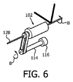
図2を参照すると、作動送出固定具の例示の構成が1つの実施形態にしたがって示されている。モータ114及びアブソリュートエンコーダ116が、2つのキャプスタン118、120及びベルト122又は他のトルク伝達機構(要素)(例えば、歯車、ホイール等)を介して送出固定具102に結合されている。送出固定具102は、OSS使用可能デバイスのための1つのファイバ128又は複数のファイバを含む。1つのファイバ又は複数のファイバの送出領域105が、送出固定具102に強固に取り付けられる。モータ114が回転するとき、送出固定具102、したがってファイバ128は回転する。実際、医者がOSS使用可能デバイス又は器具にトルクを加えるとき、OSSシステム(例えば、モジュール42、図1)は(ファイバ128を通じて)、ねじれの増加を登録する。このねじれは、ファイバ128の長さに沿った「ゼロ」の正味のねじれを確実にするように、ねじれと同じ方向に送出領域105を回転させることによって最小にされる。アブソリュートエンコーダ116は、再構成アルゴリズム又はモジュール42の中でOSS使用可能デバイスの配向を更新するために用いられる。図2の例では、回転送出固定具102は、ベルト122を使用して回され、このベルトは、モータ114によって回転させられる。エンコーダ116は、ファイバ形状が正しい座標系で正確に再構成されることができるように、送出領域105の絶対角変位を識別するために使用される。
Referring to FIG. 2, an exemplary configuration of an actuation delivery fixture is shown according to one embodiment. A
モータ114による作動は、ブラシDC、ブラシレスDC、空気式、超音波、圧電又は同様のモータ若しくはサーボを使用して達成されることができる。送出固定具102の回転によって達成可能な角速度が、臨床の回転の間に予想される回転の最大速度より高くなるべきである。アブソリュートエンコーダ116又は他のセンシング機構は、絶対又はインクリメンタルな光学、磁気、電位差測定又は同様のエンコーディングスキームを含み得る。幾つかの実施形態では、ファイバ128からの異なるねじれ信号が、継時的なゼロ位置からの送出領域102の絶対角変位を識別するために使用されることができる。
Actuation by the
他の実施形態では、ロボット作動が、X、Y及びZ方向の並進移動を含むように用いられ得る。特に、ファイバ128のZ軸に沿った並進移動が、その管腔の中のファイバ128のスティックスリップに対処するために使用されることができる。このスティックスリップ特性は、ファイバから測定されるねじれ信号のジャンプによって識別される。
In other embodiments, robot actuation can be used to include translation in the X, Y, and Z directions. In particular, translational movement of the
医者は典型的には、ねじれ蓄積を引き起こすことなしに複数ターンを通じて固定先端OSSデバイスを操作することができない。ねじれのこの蓄積は、再構成の不正確及び最終的に形状の完全な喪失につながる。本実施形態は、固定先端OSS使用可能デバイスの中の蓄積されるねじれを最小にし、操作している医者に課せられることになる操作制限の必要無しに正確な形状再構成を可能にする。 The physician typically cannot manipulate the fixed tip OSS device through multiple turns without causing twisting accumulation. This accumulation of twist leads to inaccurate reconstruction and ultimately complete loss of shape. This embodiment minimizes accumulated twists in the fixed tip OSS enabled device and allows for accurate shape reconstruction without the need for operational limitations that would be imposed on the operating physician.
図3を参照すると、グラフは、送出領域が固定されたままである間にファイバの遠位先端が4π(パイ)及び8π(パイ)両方まで回転されるときのOSSファイバのねじれ蓄積を示す。回転していないトレース(0パイ)も示されている。グラフは、先端が回転するとき最大ねじれ値が4ラジアンから18ラジアンに増加することを明確に示している。 Referring to FIG. 3, the graph shows the twist accumulation of the OSS fiber as the distal tip of the fiber is rotated to both 4π (pi) and 8π (pi) while the delivery region remains fixed. A non-rotating trace (0 pie) is also shown. The graph clearly shows that the maximum twist value increases from 4 radians to 18 radians as the tip rotates.
図4を参照すると、グラフは、遠位先端及び送出領域両方が同じ方向に4π(パイ)及び8π(パイ)回転まで回転されるときのOSSファイバのねじれ蓄積を示す。回転していないトレース(0パイ)も示されている。この場合、蓄積されたねじれのレベルは変化せず(一定のままであり)、したがって、全体的なねじれ値が、先端が受ける回転に適合するように送出領域を回転させることによって管理されることができることを明確に実証している。 Referring to FIG. 4, the graph shows twist accumulation of OSS fiber when both the distal tip and delivery region are rotated in the same direction to 4π (pi) and 8π (pi) rotations. A non-rotating trace (0 pie) is also shown. In this case, the accumulated twist level remains unchanged (and remains constant) and therefore the overall twist value is managed by rotating the delivery area to match the rotation experienced by the tip. Clearly demonstrates that it can.
続けて図2を参照しながら図5及び6を参照すると、図2は、送出固定具102のデフォルト(初期設定)位置を示している。モータ114が時計回り(矢印A)に回転するとき、送出固定具102及びファイバ128もまたそのように回転し、したがって、ファイバの配向を変化させる(図5)。図5は、医者による器具(及びしたがってファイバ128)の+30°回転を考慮するための+30°までの送出固定具102の回転を示す。モータ114が反時計回り(矢印B、図6)に回転するとき、送出固定具102及びファイバ128もまたそのように回転する。これはまた、ファイバ128の配向を変化させる。図6は、医者による器具(及びしたがってファイバ128)の−90°回転を考慮するための−90°までの送出固定具102の回転を示す。
5 and 6 with continued reference to FIG. 2, FIG. 2 shows the default (initial setting) position of the
実際、医者が器具にトルクを加えるとき、OSSシステム(コントローラ32)は、ねじれの増加を登録する。このねじれは、ファイバ128の長さに沿ったゼロの正味のねじれを確実にするようにねじれと同じ方向に送出領域を回転させることによって最小にされる。アブソリュートエンコーダ116は、再構成アルゴリズム(42、図1)の中でデバイスの配向を更新するために使用される。ファイバ128のこの回転が、ファイバ128が詰め込まれた器具の回転を引き起こすことなしに生じることに留意されたい。
In fact, when the doctor applies torque to the instrument, the OSS system (controller 32) registers an increase in twist. This twist is minimized by rotating the delivery region in the same direction as the twist to ensure zero net twist along the length of the
ベルト122は、送出固定具102及びしたがって、ファイバ送出領域(105、図5)の回転を引き起こす。エンコーダ116は、ファイバ形状が正しい座標系で正確に再構成されることができるように、送出領域105の絶対角変位を識別するために用いられる。
The
図7を参照すると、光ファイバの蓄積されるねじれを減らすための方法が示される。ブロック302では、送出固定具が、ファイバ送出領域を回転させるように構成される。固定具は、少なくとも1つの光ファイバを保持するように構成される。光学形状センシング使用可能デバイスが、少なくとも1つの光ファイバを含み、この少なくとも1つの光ファイバはその中に配置される。モータのような回転機構が、送出固定具及びしたがって送出領域を回転させるように構成される。ブロック304では、ねじれが、光学形状センシング使用可能デバイスの中に配置された少なくとも1つの光ファイバで測定される。ブロック306では、ねじれに応じて、送出領域が、少なくとも1つの光ファイバの中の蓄積されるねじれを少なくとも減少させるように、回転機構を使用して固定具において回転される。回転機構は、少なくとも1つの光ファイバにおけるねじれに反応するように構成されるモータを含み得る。回転機構は、少なくとも1つの光ファイバにおけるねじれを示す光学形状センシング信号に反応し得る、並びに/又はイメージングシステム及び/又はトラッキングシステムに反応し得る。イメージング及び/又はトラッキングシステムは、光学形状センシング使用可能デバイスの形状センシングシステムと独立している。イメージング及び/又はトラッキングシステムは、少なくとも1つの光ファイバにおけるねじれを示すために用いられ得る。
Referring to FIG. 7, a method for reducing the accumulated twist of an optical fiber is shown. At
ブロック308では、送出固定具の回転が感知される。ブロック310では、光学形状センシング使用可能デバイスの座標が回転に基づいて更新される。
In
添付の請求項を解釈する際に、
a)単語「有する」が、所定の請求項に挙げられた要素又は動作以外の要素又は動作の存在を除外しないこと、
b)要素に先行する単語「1つの」が、複数のこのような要素の存在を除外しないこと、
c)請求項のいかなる参照符号も、それらの範囲を限定しないこと、
d)幾つかの「手段」が、同じアイテム又はハードウェア又はソフトウェア実装構造又は機能により表され得ること、及び、
e)動作の特定の順序が、特に示されない限り、要求されることを意図されないこと、
が理解されるべきである。
When interpreting the appended claims,
a) the word “comprising” does not exclude the presence of elements or acts other than those listed in a given claim;
b) the word “one” preceding the element does not exclude the presence of a plurality of such elements;
c) any reference signs in the claims do not limit their scope;
d) that several “means” may be represented by the same item or hardware or software implementation structure or function; and
e) a specific order of operations is not intended to be required unless otherwise indicated;
Should be understood.
(例示的であって、限定的でないことが意図される)光学形状センシング使用可能デバイスにおけるファイバねじれを最小にするためのシステム及び方法の好適な実施例が記載されているが、修正及び変更が、上記の教示を踏まえて当業者によりなされることができることが留意される。したがって、変更が、添付の請求項により概説されるように本明細書に開示された実施形態の範囲内である開示された開示の特定の実施形態においてなされ得ることが理解されるべきである。したがって、詳細を記載し、特許法により特に要求されるが、請求項に記載され、特許証により保護されることを望むものは、添付の請求項に記載される。 Although preferred embodiments of systems and methods for minimizing fiber twist in optical shape sensing enabled devices (which are intended to be exemplary and not limiting) have been described, modifications and changes have been made. It should be noted that this can be done by those skilled in the art in light of the above teachings. Accordingly, it is to be understood that changes may be made in particular embodiments of the disclosed disclosure that are within the scope of the embodiments disclosed herein as outlined by the appended claims. Accordingly, what is described in the claims and what is specifically required by patent law, but which is desired to be protected by Letters Patent, is set forth in the appended claims.
Claims (20)
少なくとも1つの光ファイバを保持するように構成される回転可能な送出固定具、
その中に配置される前記少なくとも1つの光ファイバを含む光学形状センシング使用可能デバイス、及び
前記少なくとも1つの光ファイバの長さに沿って蓄積されるねじれを減少させるように前記少なくとも1つの光ファイバのねじれに応じて前記少なくとも1つの光ファイバを回転させるように構成される回転機構、を含む、
システム。 Fiber twist reduction system for instruments capable of optical shape sensing
A rotatable delivery fixture configured to hold at least one optical fiber;
An optical shape sensing enabled device including the at least one optical fiber disposed therein, and the at least one optical fiber to reduce twist accumulated along the length of the at least one optical fiber; A rotation mechanism configured to rotate the at least one optical fiber in response to twisting,
system.
請求項1に記載のシステム。 The rotating mechanism includes a motor configured to react to the twist of the at least one optical fiber;
The system of claim 1.
請求項2に記載のシステム。 The motor is configured to react to an optical shape sensing signal indicative of the twist of the at least one optical fiber;
The system according to claim 2.
請求項2に記載のシステム。 The motor is configured to be responsive to an imaging system, the imaging system indicating the twist of the at least one optical fiber;
The system according to claim 2.
請求項2に記載のシステム。 The motor is configured to be responsive to a tracking system, the tracking system independent of shape sensing using the optical shape sensing enabled device, and the tracking system configured to twist the twist of the at least one optical fiber. Used to show,
The system according to claim 2.
請求項1に記載のシステム。 The rotating mechanism includes a motor configured to drive a transmission element to rotate the delivery fixture;
The system of claim 1.
請求項6に記載のシステム。 The transmission element includes one of a belt, a wheel, and a gear.
The system according to claim 6.
請求項1に記載のシステム。 A sensing device configured to measure rotation of the delivery fixture;
The system of claim 1.
その中に配置される少なくとも1つの光ファイバを含む光学形状センシング使用可能デバイス、
前記少なくとも1つの光ファイバを保持するように且つ送出領域の少なくとも一部を支持するように構成される回転可能な送出固定具、
前記光ファイバの前記送出領域を回転させるように構成される回転機構、及び
前記回転機構に結合され、前記回転機構が前記少なくとも1つの光ファイバのねじれに応じて前記少なくとも1つの光ファイバの中の蓄積されるねじれを少なくとも減少させることを可能にするように構成される、コントローラ、を有する、
システム。 A fiber twist reduction system for an instrument capable of optical shape sensing, comprising:
An optical shape sensing enabled device comprising at least one optical fiber disposed therein,
A rotatable delivery fixture configured to hold the at least one optical fiber and to support at least a portion of the delivery area;
A rotating mechanism configured to rotate the delivery region of the optical fiber, and coupled to the rotating mechanism, wherein the rotating mechanism is in the at least one optical fiber in response to a twist of the at least one optical fiber. Having a controller configured to allow at least reducing accumulated twists;
system.
請求項9に記載のシステム。 The rotation mechanism includes a motor that can be used according to a twist in the at least one optical fiber.
The system according to claim 9.
請求項9に記載のシステム。 The rotating mechanism includes a motor configured to drive a transmission element to rotate the delivery fixture;
The system according to claim 9.
請求項11に記載のシステム。 The transmission element includes one of a belt, a wheel, and a gear.
The system of claim 11.
請求項9に記載のシステム。 A sensing device configured to measure rotation of the delivery fixture to update a coordinate system of the optical shape sensing enabled device;
The system according to claim 9.
請求項9に記載のシステム。 The controller includes a shape reconstruction module configured to interpret the shape of the optical shape sensing enabled device and to provide torsional feedback to the controller to operate the rotation mechanism;
The system according to claim 9.
請求項9に記載のシステム。 Further comprising an independent mechanism configured to provide torsional feedback to the controller to measure torsion and actuate the rotating mechanism;
The system according to claim 9.
少なくとの1つの光ファイバを保持するように構成される回転可能なファイバ送出固定具、その中に配置される前記少なくとも1つの光ファイバを含む光学形状センシング使用可能デバイス及び前記回転可能なファイバ送出固定具に配置される前記光ファイバを回転させるように構成される回転機構を提供するステップ、
前記光学形状センシング使用可能デバイスの中に配置される前記少なくとも1つの光ファイバのねじれを測定するステップ;並びに
前記ねじれに応じて、前記少なくとも1つの光ファイバの中の蓄積されるねじれを少なくとも減少させるように前記回転機構を使用して前記ファイバ送出固定具を回転させるステップ、を含む、
方法。 A method for reducing the accumulated twist of an optical fiber for a shape sensing enabled device comprising:
A rotatable fiber delivery fixture configured to hold at least one optical fiber, an optical shape sensing enabled device including the at least one optical fiber disposed therein, and the rotatable fiber delivery Providing a rotation mechanism configured to rotate the optical fiber disposed in a fixture;
Measuring the twist of the at least one optical fiber disposed in the optical shape sensing enabled device; and at least reducing the accumulated twist in the at least one optical fiber in response to the twist Rotating the fiber delivery fixture using the rotation mechanism as follows:
Method.
請求項16に記載の方法。 The rotating mechanism includes a motor configured to react to the twist of the at least one optical fiber;
The method of claim 16.
前記回転に応じて前記光学形状センシング使用可能デバイスの座標を更新するステップ、をさらに含む、
請求項16に記載の方法。 Sensing rotation of the delivery fixture; and updating coordinates of the optical shape sensing enabled device in response to the rotation.
The method of claim 16.
請求項16に記載の方法。 The rotating mechanism is responsive to an optical shape sensing signal indicative of the twist in the at least one optical fiber;
The method of claim 16.
請求項16に記載の方法。 The rotation mechanism is configured to be responsive to one of an imaging system and a tracking system, the one being independent of shape sensing using the optical shape sensing enabled device, wherein the imaging system and / or the tracking system is Used to indicate the twist in the at least one optical fiber;
The method of claim 16.
Applications Claiming Priority (3)
| Application Number | Priority Date | Filing Date | Title |
|---|---|---|---|
| US201361884157P | 2013-09-30 | 2013-09-30 | |
| US61/884,157 | 2013-09-30 | ||
| PCT/IB2014/064367 WO2015044815A1 (en) | 2013-09-30 | 2014-09-10 | System and method for minimizing fiber twist in optical shape sensing enabled devices |
Publications (2)
| Publication Number | Publication Date |
|---|---|
| JP2016534843A true JP2016534843A (en) | 2016-11-10 |
| JP2016534843A5 JP2016534843A5 (en) | 2017-12-07 |
Family
ID=51655793
Family Applications (1)
| Application Number | Title | Priority Date | Filing Date |
|---|---|---|---|
| JP2016545073A Pending JP2016534843A (en) | 2013-09-30 | 2014-09-10 | System and method for minimizing fiber twist in optical shape sensing enabled devices |
Country Status (5)
| Country | Link |
|---|---|
| US (1) | US9877796B2 (en) |
| EP (1) | EP3055721A1 (en) |
| JP (1) | JP2016534843A (en) |
| CN (1) | CN105612447A (en) |
| WO (1) | WO2015044815A1 (en) |
Cited By (1)
| Publication number | Priority date | Publication date | Assignee | Title |
|---|---|---|---|---|
| JP2020511255A (en) * | 2017-03-21 | 2020-04-16 | コーニンクレッカ フィリップス エヌ ヴェKoninklijke Philips N.V. | OSS guidance and monitoring system, controller and method |
Citations (4)
| Publication number | Priority date | Publication date | Assignee | Title |
|---|---|---|---|---|
| JPS6414126A (en) * | 1987-07-06 | 1989-01-18 | Hitachi Cable | Optical fiber drawing device |
| JPH0596823U (en) * | 1992-06-04 | 1993-12-27 | 旭光学工業株式会社 | Endoscope |
| WO2001033184A1 (en) * | 1999-10-29 | 2001-05-10 | Pirelli Cavi E Sistemi S.P.A. | Method of measuring the twist imparted to an optical fibre and procedure for processing an optical fibre using this method |
| WO2014188885A1 (en) * | 2013-05-22 | 2014-11-27 | オリンパス株式会社 | Curved sensor |
Family Cites Families (7)
| Publication number | Priority date | Publication date | Assignee | Title |
|---|---|---|---|---|
| US4753501A (en) * | 1986-01-15 | 1988-06-28 | The United States Of America As Represented By The Secretary Of The Air Force | Fiber optic rotary switching device |
| US7035525B2 (en) * | 2002-09-26 | 2006-04-25 | Fitel Usa Corp. | Methods and apparatuses for correcting mechanical twist in optical fiber |
| US7930065B2 (en) * | 2005-12-30 | 2011-04-19 | Intuitive Surgical Operations, Inc. | Robotic surgery system including position sensors using fiber bragg gratings |
| US8050523B2 (en) | 2007-04-20 | 2011-11-01 | Koninklijke Philips Electronics N.V. | Optical fiber shape sensing systems |
| US8335405B2 (en) | 2008-11-07 | 2012-12-18 | The United States Of America, As Represented By The Secretary Of The Navy | Method and apparatus for measuring fiber twist by polarization tracking |
| US9285246B2 (en) | 2010-02-12 | 2016-03-15 | Intuitive Surgical Operations, Inc. | Method and system for absolute three-dimensional measurements using a twist-insensitive shape sensor |
| EP2568865A1 (en) * | 2010-05-13 | 2013-03-20 | Koninklijke Philips Electronics N.V. | Rapid shape reconstruction of optical fibers |
-
2014
- 2014-09-10 US US14/917,975 patent/US9877796B2/en active Active
- 2014-09-10 WO PCT/IB2014/064367 patent/WO2015044815A1/en active Application Filing
- 2014-09-10 CN CN201480053944.3A patent/CN105612447A/en active Pending
- 2014-09-10 EP EP14777856.7A patent/EP3055721A1/en not_active Withdrawn
- 2014-09-10 JP JP2016545073A patent/JP2016534843A/en active Pending
Patent Citations (4)
| Publication number | Priority date | Publication date | Assignee | Title |
|---|---|---|---|---|
| JPS6414126A (en) * | 1987-07-06 | 1989-01-18 | Hitachi Cable | Optical fiber drawing device |
| JPH0596823U (en) * | 1992-06-04 | 1993-12-27 | 旭光学工業株式会社 | Endoscope |
| WO2001033184A1 (en) * | 1999-10-29 | 2001-05-10 | Pirelli Cavi E Sistemi S.P.A. | Method of measuring the twist imparted to an optical fibre and procedure for processing an optical fibre using this method |
| WO2014188885A1 (en) * | 2013-05-22 | 2014-11-27 | オリンパス株式会社 | Curved sensor |
Cited By (2)
| Publication number | Priority date | Publication date | Assignee | Title |
|---|---|---|---|---|
| JP2020511255A (en) * | 2017-03-21 | 2020-04-16 | コーニンクレッカ フィリップス エヌ ヴェKoninklijke Philips N.V. | OSS guidance and monitoring system, controller and method |
| JP7304814B2 (en) | 2017-03-21 | 2023-07-07 | コーニンクレッカ フィリップス エヌ ヴェ | OSS guidance and monitoring system, controller, and method |
Also Published As
| Publication number | Publication date |
|---|---|
| WO2015044815A1 (en) | 2015-04-02 |
| EP3055721A1 (en) | 2016-08-17 |
| US9877796B2 (en) | 2018-01-30 |
| CN105612447A (en) | 2016-05-25 |
| US20160206396A1 (en) | 2016-07-21 |
Similar Documents
| Publication | Publication Date | Title |
|---|---|---|
| US12114936B2 (en) | Shape sensor systems with redundant sensing | |
| KR101868081B1 (en) | Method and system for absolute three-dimensional measurements using a twist-insensitive shape sensor | |
| US11969221B2 (en) | Multipurpose lumen design for optical shape sensing | |
| US11547489B2 (en) | Shape sensing of multiple over-the-wire devices | |
| US11555692B2 (en) | Calculation of redundant bend in multi-core fiber for safety | |
| WO2014053934A1 (en) | System and method for registering shape sensing with imaging using an optimal plane | |
| JP6326483B2 (en) | System and method for minimizing torsion for optical shape detection enabled devices | |
| JP2016534843A (en) | System and method for minimizing fiber twist in optical shape sensing enabled devices |
Legal Events
| Date | Code | Title | Description |
|---|---|---|---|
| A621 | Written request for application examination |
Free format text: JAPANESE INTERMEDIATE CODE: A621 Effective date: 20170907 |
|
| A521 | Request for written amendment filed |
Free format text: JAPANESE INTERMEDIATE CODE: A523 Effective date: 20171025 |
|
| A871 | Explanation of circumstances concerning accelerated examination |
Free format text: JAPANESE INTERMEDIATE CODE: A871 Effective date: 20171025 |
|
| A975 | Report on accelerated examination |
Free format text: JAPANESE INTERMEDIATE CODE: A971005 Effective date: 20171129 |
|
| A131 | Notification of reasons for refusal |
Free format text: JAPANESE INTERMEDIATE CODE: A131 Effective date: 20171205 |
|
| A02 | Decision of refusal |
Free format text: JAPANESE INTERMEDIATE CODE: A02 Effective date: 20180626 |