JP7304814B2 - OSS guidance and monitoring system, controller, and method - Google Patents
OSS guidance and monitoring system, controller, and method Download PDFInfo
- Publication number
- JP7304814B2 JP7304814B2 JP2019551648A JP2019551648A JP7304814B2 JP 7304814 B2 JP7304814 B2 JP 7304814B2 JP 2019551648 A JP2019551648 A JP 2019551648A JP 2019551648 A JP2019551648 A JP 2019551648A JP 7304814 B2 JP7304814 B2 JP 7304814B2
- Authority
- JP
- Japan
- Prior art keywords
- oss
- interventional
- node
- interventional device
- proximal
- Prior art date
- Legal status (The legal status is an assumption and is not a legal conclusion. Google has not performed a legal analysis and makes no representation as to the accuracy of the status listed.)
- Active
Links
- 238000012544 monitoring process Methods 0.000 title claims description 65
- 238000000034 method Methods 0.000 title description 39
- 210000003484 anatomy Anatomy 0.000 claims description 110
- 238000005452 bending Methods 0.000 claims description 89
- 230000000007 visual effect Effects 0.000 claims description 23
- 230000010354 integration Effects 0.000 claims description 19
- 238000012806 monitoring device Methods 0.000 claims description 12
- 238000013519 translation Methods 0.000 claims description 12
- 230000008859 change Effects 0.000 claims description 7
- 230000005540 biological transmission Effects 0.000 claims description 2
- 238000006073 displacement reaction Methods 0.000 claims 1
- 239000013307 optical fiber Substances 0.000 description 30
- 238000007373 indentation Methods 0.000 description 25
- 238000001514 detection method Methods 0.000 description 20
- 238000003384 imaging method Methods 0.000 description 20
- 230000003287 optical effect Effects 0.000 description 18
- 230000004913 activation Effects 0.000 description 17
- 230000015654 memory Effects 0.000 description 16
- 230000008569 process Effects 0.000 description 11
- 230000004044 response Effects 0.000 description 11
- 230000014616 translation Effects 0.000 description 11
- 210000005166 vasculature Anatomy 0.000 description 10
- 239000000835 fiber Substances 0.000 description 9
- 238000013152 interventional procedure Methods 0.000 description 9
- 239000013598 vector Substances 0.000 description 9
- 238000013507 mapping Methods 0.000 description 8
- 230000000670 limiting effect Effects 0.000 description 7
- 238000010801 machine learning Methods 0.000 description 6
- 238000012545 processing Methods 0.000 description 6
- 238000012360 testing method Methods 0.000 description 6
- 230000008901 benefit Effects 0.000 description 5
- 238000004891 communication Methods 0.000 description 5
- 238000013459 approach Methods 0.000 description 4
- 230000001902 propagating effect Effects 0.000 description 4
- 210000002345 respiratory system Anatomy 0.000 description 4
- 230000002792 vascular Effects 0.000 description 4
- 210000004204 blood vessel Anatomy 0.000 description 3
- 210000000748 cardiovascular system Anatomy 0.000 description 3
- 230000009849 deactivation Effects 0.000 description 3
- 210000002249 digestive system Anatomy 0.000 description 3
- 230000006870 function Effects 0.000 description 3
- 239000011521 glass Substances 0.000 description 3
- 238000003780 insertion Methods 0.000 description 3
- 230000037431 insertion Effects 0.000 description 3
- 210000000936 intestine Anatomy 0.000 description 3
- 238000002372 labelling Methods 0.000 description 3
- 210000004072 lung Anatomy 0.000 description 3
- 238000005259 measurement Methods 0.000 description 3
- 238000002324 minimally invasive surgery Methods 0.000 description 3
- 230000000399 orthopedic effect Effects 0.000 description 3
- 230000001681 protective effect Effects 0.000 description 3
- 230000002829 reductive effect Effects 0.000 description 3
- 210000002784 stomach Anatomy 0.000 description 3
- 230000009897 systematic effect Effects 0.000 description 3
- VYPSYNLAJGMNEJ-UHFFFAOYSA-N Silicium dioxide Chemical compound O=[Si]=O VYPSYNLAJGMNEJ-UHFFFAOYSA-N 0.000 description 2
- 238000010586 diagram Methods 0.000 description 2
- 210000005095 gastrointestinal system Anatomy 0.000 description 2
- 230000006872 improvement Effects 0.000 description 2
- 238000002608 intravascular ultrasound Methods 0.000 description 2
- 239000000463 material Substances 0.000 description 2
- 210000002346 musculoskeletal system Anatomy 0.000 description 2
- 239000004033 plastic Substances 0.000 description 2
- 230000002441 reversible effect Effects 0.000 description 2
- 239000000523 sample Substances 0.000 description 2
- 239000004065 semiconductor Substances 0.000 description 2
- 230000003068 static effect Effects 0.000 description 2
- 238000012800 visualization Methods 0.000 description 2
- 229920002614 Polyether block amide Polymers 0.000 description 1
- 230000002411 adverse Effects 0.000 description 1
- 238000003491 array Methods 0.000 description 1
- 230000004397 blinking Effects 0.000 description 1
- 210000001072 colon Anatomy 0.000 description 1
- 238000004590 computer program Methods 0.000 description 1
- 230000008878 coupling Effects 0.000 description 1
- 238000010168 coupling process Methods 0.000 description 1
- 238000005859 coupling reaction Methods 0.000 description 1
- 239000006185 dispersion Substances 0.000 description 1
- 230000002526 effect on cardiovascular system Effects 0.000 description 1
- 210000000750 endocrine system Anatomy 0.000 description 1
- 238000005516 engineering process Methods 0.000 description 1
- 210000004907 gland Anatomy 0.000 description 1
- 238000009434 installation Methods 0.000 description 1
- 210000001613 integumentary system Anatomy 0.000 description 1
- 230000003993 interaction Effects 0.000 description 1
- 210000003734 kidney Anatomy 0.000 description 1
- 230000004807 localization Effects 0.000 description 1
- 210000001165 lymph node Anatomy 0.000 description 1
- 210000004324 lymphatic system Anatomy 0.000 description 1
- 239000002184 metal Substances 0.000 description 1
- 238000012986 modification Methods 0.000 description 1
- 230000004048 modification Effects 0.000 description 1
- 230000003387 muscular Effects 0.000 description 1
- 210000000653 nervous system Anatomy 0.000 description 1
- HLXZNVUGXRDIFK-UHFFFAOYSA-N nickel titanium Chemical compound [Ti].[Ti].[Ti].[Ti].[Ti].[Ti].[Ti].[Ti].[Ti].[Ti].[Ti].[Ni].[Ni].[Ni].[Ni].[Ni].[Ni].[Ni].[Ni].[Ni].[Ni].[Ni].[Ni].[Ni].[Ni] HLXZNVUGXRDIFK-UHFFFAOYSA-N 0.000 description 1
- 229910001000 nickel titanium Inorganic materials 0.000 description 1
- 238000002168 optical frequency-domain reflectometry Methods 0.000 description 1
- 210000000496 pancreas Anatomy 0.000 description 1
- 230000000737 periodic effect Effects 0.000 description 1
- 230000002093 peripheral effect Effects 0.000 description 1
- 239000005365 phosphate glass Substances 0.000 description 1
- 230000000644 propagated effect Effects 0.000 description 1
- 230000009467 reduction Effects 0.000 description 1
- 238000002310 reflectometry Methods 0.000 description 1
- 210000004994 reproductive system Anatomy 0.000 description 1
- 230000000241 respiratory effect Effects 0.000 description 1
- 239000000377 silicon dioxide Substances 0.000 description 1
- 239000007787 solid Substances 0.000 description 1
- 238000011477 surgical intervention Methods 0.000 description 1
- 238000001356 surgical procedure Methods 0.000 description 1
- 230000001360 synchronised effect Effects 0.000 description 1
- 238000012546 transfer Methods 0.000 description 1
- 230000009466 transformation Effects 0.000 description 1
- 238000002604 ultrasonography Methods 0.000 description 1
- 230000002485 urinary effect Effects 0.000 description 1
- 210000004291 uterus Anatomy 0.000 description 1
Images


Classifications
-
- A—HUMAN NECESSITIES
- A61—MEDICAL OR VETERINARY SCIENCE; HYGIENE
- A61B—DIAGNOSIS; SURGERY; IDENTIFICATION
- A61B34/00—Computer-aided surgery; Manipulators or robots specially adapted for use in surgery
- A61B34/30—Surgical robots
-
- A—HUMAN NECESSITIES
- A61—MEDICAL OR VETERINARY SCIENCE; HYGIENE
- A61B—DIAGNOSIS; SURGERY; IDENTIFICATION
- A61B34/00—Computer-aided surgery; Manipulators or robots specially adapted for use in surgery
- A61B34/20—Surgical navigation systems; Devices for tracking or guiding surgical instruments, e.g. for frameless stereotaxis
-
- A—HUMAN NECESSITIES
- A61—MEDICAL OR VETERINARY SCIENCE; HYGIENE
- A61B—DIAGNOSIS; SURGERY; IDENTIFICATION
- A61B34/00—Computer-aided surgery; Manipulators or robots specially adapted for use in surgery
- A61B34/70—Manipulators specially adapted for use in surgery
- A61B34/76—Manipulators having means for providing feel, e.g. force or tactile feedback
-
- A—HUMAN NECESSITIES
- A61—MEDICAL OR VETERINARY SCIENCE; HYGIENE
- A61B—DIAGNOSIS; SURGERY; IDENTIFICATION
- A61B5/00—Measuring for diagnostic purposes; Identification of persons
- A61B5/06—Devices, other than using radiation, for detecting or locating foreign bodies ; Determining position of diagnostic devices within or on the body of the patient
- A61B5/065—Determining position of the probe employing exclusively positioning means located on or in the probe, e.g. using position sensors arranged on the probe
-
- B—PERFORMING OPERATIONS; TRANSPORTING
- B25—HAND TOOLS; PORTABLE POWER-DRIVEN TOOLS; MANIPULATORS
- B25J—MANIPULATORS; CHAMBERS PROVIDED WITH MANIPULATION DEVICES
- B25J19/00—Accessories fitted to manipulators, e.g. for monitoring, for viewing; Safety devices combined with or specially adapted for use in connection with manipulators
- B25J19/02—Sensing devices
- B25J19/021—Optical sensing devices
- B25J19/025—Optical sensing devices including optical fibres
-
- G—PHYSICS
- G01—MEASURING; TESTING
- G01D—MEASURING NOT SPECIALLY ADAPTED FOR A SPECIFIC VARIABLE; ARRANGEMENTS FOR MEASURING TWO OR MORE VARIABLES NOT COVERED IN A SINGLE OTHER SUBCLASS; TARIFF METERING APPARATUS; MEASURING OR TESTING NOT OTHERWISE PROVIDED FOR
- G01D5/00—Mechanical means for transferring the output of a sensing member; Means for converting the output of a sensing member to another variable where the form or nature of the sensing member does not constrain the means for converting; Transducers not specially adapted for a specific variable
- G01D5/26—Mechanical means for transferring the output of a sensing member; Means for converting the output of a sensing member to another variable where the form or nature of the sensing member does not constrain the means for converting; Transducers not specially adapted for a specific variable characterised by optical transfer means, i.e. using infrared, visible, or ultraviolet light
- G01D5/32—Mechanical means for transferring the output of a sensing member; Means for converting the output of a sensing member to another variable where the form or nature of the sensing member does not constrain the means for converting; Transducers not specially adapted for a specific variable characterised by optical transfer means, i.e. using infrared, visible, or ultraviolet light with attenuation or whole or partial obturation of beams of light
- G01D5/34—Mechanical means for transferring the output of a sensing member; Means for converting the output of a sensing member to another variable where the form or nature of the sensing member does not constrain the means for converting; Transducers not specially adapted for a specific variable characterised by optical transfer means, i.e. using infrared, visible, or ultraviolet light with attenuation or whole or partial obturation of beams of light the beams of light being detected by photocells
- G01D5/353—Mechanical means for transferring the output of a sensing member; Means for converting the output of a sensing member to another variable where the form or nature of the sensing member does not constrain the means for converting; Transducers not specially adapted for a specific variable characterised by optical transfer means, i.e. using infrared, visible, or ultraviolet light with attenuation or whole or partial obturation of beams of light the beams of light being detected by photocells influencing the transmission properties of an optical fibre
-
- G—PHYSICS
- G02—OPTICS
- G02B—OPTICAL ELEMENTS, SYSTEMS OR APPARATUS
- G02B6/00—Light guides; Structural details of arrangements comprising light guides and other optical elements, e.g. couplings
- G02B6/02—Optical fibres with cladding with or without a coating
- G02B6/02057—Optical fibres with cladding with or without a coating comprising gratings
- G02B6/02076—Refractive index modulation gratings, e.g. Bragg gratings
- G02B6/02195—Refractive index modulation gratings, e.g. Bragg gratings characterised by means for tuning the grating
- G02B6/022—Refractive index modulation gratings, e.g. Bragg gratings characterised by means for tuning the grating using mechanical stress, e.g. tuning by compression or elongation, special geometrical shapes such as "dog-bone" or taper
-
- A—HUMAN NECESSITIES
- A61—MEDICAL OR VETERINARY SCIENCE; HYGIENE
- A61B—DIAGNOSIS; SURGERY; IDENTIFICATION
- A61B34/00—Computer-aided surgery; Manipulators or robots specially adapted for use in surgery
- A61B34/20—Surgical navigation systems; Devices for tracking or guiding surgical instruments, e.g. for frameless stereotaxis
- A61B2034/2046—Tracking techniques
- A61B2034/2061—Tracking techniques using shape-sensors, e.g. fiber shape sensors with Bragg gratings
Landscapes
- Health & Medical Sciences (AREA)
- Engineering & Computer Science (AREA)
- Life Sciences & Earth Sciences (AREA)
- Surgery (AREA)
- Physics & Mathematics (AREA)
- Veterinary Medicine (AREA)
- Heart & Thoracic Surgery (AREA)
- Medical Informatics (AREA)
- Molecular Biology (AREA)
- Animal Behavior & Ethology (AREA)
- General Health & Medical Sciences (AREA)
- Public Health (AREA)
- Biomedical Technology (AREA)
- Robotics (AREA)
- Nuclear Medicine, Radiotherapy & Molecular Imaging (AREA)
- General Physics & Mathematics (AREA)
- Biophysics (AREA)
- Pathology (AREA)
- Human Computer Interaction (AREA)
- Optics & Photonics (AREA)
- Mechanical Engineering (AREA)
- Endoscopes (AREA)
Description
本開示の発明は、概して、患者の解剖学的システム内の介入ツールのナビゲーションを誘導するための光学的形状感知(OSS)技術(例えば、患者の心血管系、呼吸器系、又は消化器系内でナビゲートされる介入ツールに統合されたOSSセンサの線形的/曲線的並進及び/又は軸方向/非軸方向回転の追跡)を実施するシステム、コントローラ、及び方法に関する。 The presently disclosed invention generally utilizes Optical Shape Sensing (OSS) technology for guiding the navigation of interventional tools within a patient's anatomical system (e.g., the patient's cardiovascular, respiratory, or gastrointestinal systems). Systems, controllers, and methods for performing linear/curvilinear translation and/or axial/non-axial rotation tracking of OSS sensors integrated into interventional tools navigated within.
本開示の発明は、より具体的には、患者の解剖学的システム内の介入ツールのナビゲーションの光学的形状感知(OSS)誘導の監視(例えば、介入ツールが患者の心血管系、呼吸器系、又は消化器系の内腔内で線形的/曲線的に並進する及び/又は軸方向/非軸方向に回転するときのOSSセンサの任意の折れ曲がり及び/又は任意のねじれの監視)を提供することによってそのようなシステム、コントローラ、及び方法を改善することに関する。 The invention of the present disclosure more specifically provides optical shape sensing (OSS)-guided monitoring of the navigation of an interventional tool within a patient's anatomical system (e.g., if the interventional tool , or any bending and/or twisting of the OSS sensor as it linearly/curvilinearly translates and/or axially/non-axially rotates within the lumen of the gastrointestinal system). It thus relates to improving such systems, controllers and methods.
光学的形状感知(OSS)は、外科的介入中のデバイスの位置特定及びナビゲーションのためにシングルコア又はマルチコアの光ファイバに沿った光を使用する。関連する原理は、特徴的なレイリー後方散乱又は制御されたグレーティングパターンを使用する光ファイバ内の分散歪み測定を利用する。光ファイバに沿った形状は、ランチ又はz=0として知られるセンサに沿った特定の点から始まり、光ファイバのその後の形状位置及び方向は、その点に関連する。 Optical shape sensing (OSS) uses light along single- or multi-core optical fibers for device localization and navigation during surgical interventions. A related principle utilizes dispersion strain measurements in optical fibers using characteristic Rayleigh backscattering or controlled grating patterns. The shape along the fiber begins at a particular point along the sensor known as the launch or z=0, and subsequent shape positions and orientations of the fiber are related to that point.
低侵襲処置中に介入ツールのモニタを介してライブ視覚誘導を提供するために、OSSファイバが介入ツール(例えば、血管ツール、腔内ツール、整形外科ツール)に統合され、それによって、統合されたOSSファイバは、介入ツールの一部又は全体の位置(すなわち、位置及び/又は方向)を提供する。介入ツールのライブ視覚誘導は、低侵襲処置の成功を容易にするのに有利であると証明されているが、介入ツールの「押し込み性」及び「トルク伝達性」の問題は、介入ツールの潜在的な「座屈」及び潜在的な「しなり」への懸念である。 OSS fibers have been integrated into interventional tools (e.g., vascular, endoluminal, orthopedic tools) to provide live visual guidance via monitoring of interventional tools during minimally invasive procedures, thereby integrating The OSS fiber provides the position (ie position and/or orientation) of part or all of the interventional tool. Live visual guidance of interventional tools has proven advantageous in facilitating the success of minimally invasive procedures, but the problem of "pushability" and "torqueability" of interventional tools is the potential for interventional tools. This is a concern with the inherent "buckling" and potential "bending".
例えば、血管ナビゲーションはカテーテルをガイドワイヤの上に通過させることによって実行され、それによって、ガイドワイヤとカテーテルとの間の機械的相互作用が、主に(1)血管系内のガイドワイヤ及び/若しくはカテーテルの前進及び/若しくは後退、並びに/又は(2)血管系内のガイドワイヤ及び/若しくはカテーテルの回転からなる。 For example, vascular navigation is performed by passing a catheter over a guidewire, whereby the mechanical interaction between the guidewire and the catheter primarily affects (1) the guidewire and/or Advancement and/or retraction of the catheter and/or (2) rotation of the guidewire and/or catheter within the vasculature.
理想的には、ガイドワイヤ及びカテーテルは、(1)患者に無関係なガイドワイヤの近位セグメント及び/又は患者に無関係なカテーテルの近位セグメントのオペレータ制御の並進及び/又は回転と、(2)患者内のガイドワイヤの遠位セグメント及び/又はカテーテルの遠位セグメントの対応する並進及び/又は回転との間の1対1のマッピングを有する。 Ideally, the guidewires and catheters are configured for (1) operator-controlled translation and/or rotation of the proximal segment of the patient-independent guidewire and/or the proximal segment of the patient-independent catheter; It has a one-to-one mapping between corresponding translations and/or rotations of the distal segment of the guidewire and/or the distal segment of the catheter within the patient.
ガイドワイヤ及びカテーテルの両方のセグメントが真っ直ぐで硬い場合、ガイドワイヤ及びカテーテルは、近位セグメントと遠位セグメントとの間に前述の1対1のマッピングを有する。しかしながら、低侵襲処置では、ガイドワイヤの遠位セグメント及びカテーテルの遠位セグメントは、曲がりくねった血管系を通ってナビゲートされるのに十分な可撓性でなければならない。そのような可撓性は、ガイドワイヤ及び/又はカテーテルの押し込み性及び/又はトルク伝達性を低下させることがある。 If both the guidewire and catheter segments are straight and stiff, the guidewire and catheter have the aforementioned one-to-one mapping between the proximal and distal segments. However, for minimally invasive procedures, the distal segment of the guidewire and the distal segment of the catheter must be flexible enough to be navigated through tortuous vasculature. Such flexibility may reduce the pushability and/or torqueability of the guidewire and/or catheter.
より具体的には、押し込み性は、無関係の近位セグメントが血管系内で遠位セグメントを前進又は後退させるためにオペレータ制御又はロボット制御されるときの、ガイドワイヤ及び/又はカテーテルの近位セグメントと遠位セグメントとの間の1対1マッピングの達成可能な程度に関する。ガイドワイヤ及び/又はカテーテルの押し込み性の低下は、血管系内のガイドワイヤ及び/又はカテーテルの遠位セグメントのある程度の折れ曲がりをもたらすことがあり、それによって、折れ曲がりは、血管系内のガイドワイヤ及び/若しくはカテーテルの操作及び誘導に悪影響を及ぼすことがあり、並びに/又は血管系内に過度のストレスを加える場合がある。 More specifically, pushability is defined by the proximal segment of a guidewire and/or catheter when an unrelated proximal segment is operator-controlled or robotically controlled to advance or retract the distal segment within the vasculature. and the achievable degree of one-to-one mapping between . Reduced pushability of the guidewire and/or catheter may result in some degree of kinking of the distal segment of the guidewire and/or catheter within the vasculature, whereby the kinking reduces the guidewire and/or catheter within the vasculature. /or may adversely affect manipulation and guidance of the catheter and/or may place undue stress within the vasculature.
トルク伝達性は、無関係な近位セグメントが血管系内で遠位セグメントを回転させるためにオペレータ制御又はロボット制御されるときの、ガイドワイヤ及び/又はカテーテルの近位セグメントと遠位セグメントとの間の1対1マッピングの達成可能な程度に関する。ガイドワイヤ及び/又はカテーテルのトルク伝達性の低下は、血管系内のガイドワイヤ及び/又はカテーテルの遠位セグメントのある程度のねじれをもたらす場合があり、それによって、ねじれは、血管系内のガイドワイヤ及び/若しくはカテーテルを潜在的且つ危険なほどにしなることがあり、並びに/又は血管系内に過度のストレスを加えることもある。低下したトルク伝達性は、ガイドワイヤ及び/又はカテーテルの最適な操作及び誘導を妨げることもある。 Torqueability is between the proximal and distal segments of the guidewire and/or catheter when the unrelated proximal segment is operator-controlled or robot-controlled to rotate the distal segment within the vasculature. about the achievable degree of one-to-one mapping of . Reduced torqueability of the guidewire and/or catheter may result in some degree of twisting of the distal segment of the guidewire and/or catheter within the vasculature, whereby the twisting is and/or may potentially and dangerously strain the catheter and/or place undue stress within the vasculature. Reduced torqueability may prevent optimal manipulation and guidance of the guidewire and/or catheter.
したがって、患者内の介入ツールの任意の潜在的な座屈を検出する必要があり、これは、介入ツールの折れ曲がりによる患者の解剖学的領域内の介入ツールのナビゲートされた形状の描写された許容できない程度の歪みである。 Therefore, there is a need to detect any potential buckling of the interventional tool within the patient, which is the delineated shape of the interventional tool's navigated shape within the patient's anatomical region due to bending of the interventional tool. Distortion is unacceptable.
患者内の介入ツールの任意の潜在的なしなりを検出する必要もあり、これは、介入ツールのねじれによる患者の解剖学的領域内の介入ツールのナビゲートされた形状の描写された許容できない程度の歪みである。 There is also a need to detect any potential flexing of the interventional tool within the patient, which is a delineated unacceptable degree of the navigated shape of the interventional tool within the patient's anatomical region due to twisting of the interventional tool. distortion.
光学的形状感知(OSS)誘導システム、コントローラ、及び方法を改善するために、本開示は、介入デバイスが解剖学的領域内の介入デバイスの線形的/曲線的並進によって及び/又は解剖学的領域内の介入デバイスの軸方向/非軸方向回転によって解剖学的領域内をナビゲートされるときに、介入ツールとOSSセンサとの統合を含む介入デバイスの任意の折れ曲がり及び/又は任意のねじれを検出するための発明を提供する。 To improve Optical Shape Sensing (OSS) guidance systems, controllers, and methods, the present disclosure provides for interventional devices to be controlled by linear/curvilinear translation of the interventional device within an anatomical region and/or the anatomical region. Detect any bending and/or twisting of the interventional device, including integration of interventional tools and OSS sensors, as navigated within the anatomical region by axial/non-axial rotation of the interventional device within To provide an invention for
本開示の発明を説明し特許請求する目的のために、
(1)「解剖学的領域」という用語は、本開示の技術分野で知られているように、そして本開示で例示的に説明するように、1つ又は複数の解剖学的システムを広く包含し、各解剖学的システムは、その中に介入デバイスのナビゲーションのための自然又は外科的構造を有している。解剖学的領域の例は、限定はしないが、外皮系(例えば、皮膚及び付属器)、骨格系、筋肉系、神経系、内分泌系(例えば、腺及び膵臓)、消化器系(例えば、胃、腸、及び結腸)、呼吸器系(例えば、気道及び肺)、循環器系(例えば、心臓及び血管)、リンパ系(例えば、リンパ節)、泌尿器系(例えば、腎臓)、及び生殖系(例えば、子宮)を含む。
(2)「介入ツール」という用語は、本開示の前又は後に知られる介入ツールを含み、本開示の技術分野で知られているように広く解釈されるべきである。介入ツールの例は、限定はしないが、血管介入ツール(例えば、ガイドワイヤ、カテーテル、ステントシース、バルーン、アテローム切除カテーテル、IVUSイメージングプローブ、展開システムなど)、管腔内介入ツール(例えば、内視鏡、気管支鏡など)、及び整形外科的介入ツール(例えば、kワイヤ及びねじ回し)を含む。
(3)「ツールノード」という用語は、本開示の技術分野で知られている介入ツールの単一の点、複数の点、セグメント、テンプレート(例えば、形状、湾曲、又は歪み)、又はそれ以外の任意の部分を広く包含し、「近位ツールノード」又は「遠位ツールノード」としてのツールノードのラベリングは、その特定のツールノードの介入デバイスの別のツールノードに対する相対的な長手方向の間隔を特徴付け、介入ツールの構成内のその特定のツールノードの正確な位置を特徴付けない。
(4)「OSSセンサ」という用語は、光ファイバに放射され、光ファイバを通って伝播し、光ファイバ内で伝播光の反対方向に反射される及び/又は光ファイバから伝播光の方向に伝送される光から導出される光ファイバの高密度歪み測定値を抽出するための、本開示の技術分野で知られるように、且つ以下で考えられるように構造的に構成された光ファイバを広く包含する。OSSセンサの例は、限定はしないが、光ファイバ内の制御されたグレーティングパターン(例えば、ファイバブラッググレーティング)、光ファイバの特徴的な後方散乱(例えば、レイリー後方散乱)、又は光ファイバ内に埋め込まれた、エッチングされた、インプリントされた、若しくは別のやり方で形成された反射ノード要素及び/若しくは透過ノード要素の任意の他の配置を介して、光ファイバに放射され、光ファイバを通って伝播し、光ファイバ内で伝播光の反対方向に反射される及び/又は光ファイバから伝播光の方向に伝送される光から導出される光ファイバの高密度歪み測定値を抽出するための光周波数領域反射測定(OFDR)の原理の下で構造的に構成された光ファイバを含む。
(5)「OSSノード」という用語は、本開示の技術分野で知られているOSSセンサの任意の反射ノード要素又は任意の透過ノード要素を広く包含し、「近位OSSノード」又は「遠位OSSノード」としてのOSSノードのラベリングは、本開示で例示的に説明するように、その特定のOSSノードの別のOSSノードに対する相対的な長手方向の間隔を特徴付け、OSSセンサの構造的構成内のその特定のOSSノードの正確な位置を特徴付けない。
(6)「介入ツールとOSSセンサとの統合」という語句は、本開示の技術分野で理解されるように、且つ例示的に説明されているように、介入ツール及びOSSセンサの介入デバイスへの任意のタイプの結合、接合、取り付け、据え付け、挿入、混ぜ合わせ、又はその他の統合を広く包含する。そのような統合の例は、限定はしないが、カテーテルのチャネル内へのOSSセンサの固定挿入、及びOSSセンサを組み込んだガイドワイヤを含む。
(7)「デバイスノード」という用語は、本開示の技術分野で知られている介入デバイスの単一の点、複数の点、セグメント、テンプレート(例えば、形状、湾曲、又は歪み)、又はそれ以外の任意の部分を広く包含し、「近位デバイスノード」又は「遠位デバイスノード」としてのデバイスノードのラベリングは、その特定のデバイスノードの介入デバイスの別のデバイスノードに対する相対的な長手方向の間隔を特徴付け、介入デバイスの構成内のその特定のデバイスノードの正確な位置を特徴付けない。デバイスノードの例は、限定はしないが、OSSセンサのOSSノード、及びOSSセンサのOSSノードにマッピングされた介入ツールのツールノードを含む。
(8)「介入デバイスの折れ曲がり」という語句は、本開示の技術分野で理解されるように、且つ本明細書で例示的に説明されているように、解剖学的領域に無関係な介入デバイスの近位デバイスノードと解剖学的領域内の介入デバイスの遠位デバイスノードとの間の長手方向の間隔の任意の減少を広く包含する。
(9)「介入デバイスのねじれ」という語句は、本開示の技術分野で理解されるように、且つ本明細書で例示的に説明されているように、解剖学的領域に無関係な介入デバイスの近位デバイスノードと解剖学的領域内のOSSセンサの遠位デバイスノードとの間の角度方向の任意の増加を広く包含する。
For the purposes of describing and claiming the invention of this disclosure:
(1) The term "anatomical region" broadly encompasses one or more anatomical systems, as known in the art of this disclosure and as illustratively described in this disclosure. However, each anatomical system has within it natural or surgical structures for navigation of interventional devices. Examples of anatomical regions include, but are not limited to, integumentary system (e.g., skin and appendages), skeletal system, muscular system, nervous system, endocrine system (e.g., glands and pancreas), digestive system (e.g., stomach). , intestine, and colon), respiratory system (e.g., airways and lungs), circulatory system (e.g., heart and blood vessels), lymphatic system (e.g., lymph nodes), urinary system (e.g., kidneys), and reproductive system ( e.g. uterus).
(2) The term "interventional tool" includes interventional tools known before or after the present disclosure, and should be interpreted broadly as known in the technical field of the present disclosure. Examples of interventional tools include, but are not limited to, vascular interventional tools (e.g., guidewires, catheters, stent sheaths, balloons, atherectomy catheters, IVUS imaging probes, deployment systems, etc.), endoluminal interventional tools (e.g., endoscopic scopes, bronchoscopes, etc.), and orthopedic interventional tools (eg, k-wires and screwdrivers).
(3) The term "tool node" refers to a single point, multiple points, segments, templates (e.g., shape, curvature, or distortion), or otherwise of an interventional tool known in the art of this disclosure. and the labeling of a tool node as "proximal tool node" or "distal tool node" refers to the relative longitudinal extent of that particular tool node to another tool node of the interventional device. It characterizes the spacing and not the exact location of that particular tool node within the configuration of interventional tools.
(4) The term "OSS sensor" means a sensor that is emitted into, propagates through, and is reflected within the optical fiber in the opposite direction of the propagating light and/or transmitted from the optical fiber in the direction of the propagating light. broadly encompasses optical fibers that are structurally configured as known in the art of the present disclosure and as contemplated below for extracting high-density strain measurements of optical fibers derived from light emitted from do. Examples of OSS sensors include, but are not limited to, controlled grating patterns in optical fibers (e.g., fiber Bragg gratings), characteristic backscattering of optical fibers (e.g., Rayleigh backscattering), or embedded in optical fibers. via any other arrangement of reflective and/or transmissive node elements etched, etched, imprinted, or otherwise formed into and through the optical fiber. Optical frequencies for extracting high-density strain measurements in optical fibers derived from light that propagates and is reflected in the fiber in the opposite direction of the propagating light and/or transmitted out of the optical fiber in the direction of the propagating light It includes an optical fiber that is structurally constructed under the principle of area reflectometry (OFDR).
(5) The term "OSS node" broadly encompasses any reflective node element or any transmissive node element of an OSS sensor known in the art of this disclosure, and includes a "proximal OSS node" or a "distal The labeling of an OSS node as"the OSS node" characterizes the relative longitudinal spacing of that particular OSS node to another OSS node, and the structural configuration of the OSS sensor, as illustratively described in this disclosure. It does not characterize the exact location of that particular OSS node within.
(6) The phrase "integration of interventional tools and OSS sensors" means integration of interventional tools and OSS sensors into interventional devices, as understood and illustratively described in the technical field of this disclosure. It broadly encompasses any type of coupling, joining, attachment, installation, insertion, intermingling, or other integration. Examples of such integration include, but are not limited to, fixed insertion of OSS sensors into channels of catheters, and guidewires incorporating OSS sensors.
(7) The term "device node" refers to a single point, multiple points, segments, templates (e.g., shape, curvature, or distortion), or otherwise of an interventional device known in the art of this disclosure. and the labeling of a device node as "proximal device node" or "distal device node" refers to the relative longitudinal length of that particular device node's interventional device to another device node. It characterizes the spacing and does not characterize the exact location of that particular device node within the configuration of the interventional device. Examples of device nodes include, but are not limited to, OSS nodes of OSS sensors and tool nodes of intervention tools mapped to OSS nodes of OSS sensors.
(8) The phrase "interventional device bend" refers to an interventional device that is unrelated to an anatomical region, as understood in the art of this disclosure and illustratively described herein. Broadly encompasses any reduction in longitudinal spacing between a proximal device node and a distal device node of an interventional device within an anatomical region.
(9) The phrase "torsion of an interventional device", as understood in the technical field of this disclosure and as illustratively described herein, refers to the Broadly encompasses any increase in angular orientation between the proximal device node and the distal device node of the OSS sensor within the anatomical region.
本開示の発明の一実施形態は、FORセンサと1つ又は複数の介入ツールとの統合を含む介入デバイスを用いるOSS誘導及び監視システムである。OSS誘導及び監視システムは、OSS誘導コントローラとOSS監視コントローラとを含むOSS誘導及び監視デバイスをさらに用いる。 One embodiment of the disclosed invention is an OSS guidance and monitoring system using interventional devices that include integration of FOR sensors with one or more interventional tools. The OSS guidance and monitoring system further employs OSS guidance and monitoring devices including an OSS guidance controller and an OSS supervisory controller.
動作中、介入デバイスが解剖学的領域内でナビゲートされる(例えば、解剖学的領域内で並進及び/又は回転される)とき、OSSセンサは、OSSセンサの形状の情報を与える形状感知データを生成する。 In operation, as the interventional device is navigated within the anatomical region (e.g., translated and/or rotated within the anatomical region), the OSS sensor generates shape sensing data that informs the shape of the OSS sensor. to generate
OSS誘導コントローラは、OSSセンサによる形状感知データの生成に応答して、解剖学的領域内の介入デバイスの形状の再構成を制御する。 The OSS guidance controller controls shape reconstruction of the interventional device within the anatomical region in response to generation of shape sensing data by the OSS sensor.
OSS監視コントローラは、OSSセンサによる形状感知データの生成に応答して押し込み性メトリック及び/又はトルク伝達性メトリックを生成することによって、解剖学的領域内の介入デバイスの折れ曲がりの程度及び/又はねじれの程度の監視を制御する。 The OSS monitoring controller measures the degree of tortuosity and/or torsion of the interventional device within the anatomical region by generating a pushability metric and/or a torquability metric in response to the generation of shape sensing data by the OSS sensor. Control the degree of monitoring.
押し込み性メトリックは、介入デバイスの近位デバイスノードと遠位デバイスノードとの間の介入デバイスの推定される折れ曲がりの程度を定量化する。 The pushability metric quantifies the estimated degree of bending of the interventional device between the proximal and distal device nodes of the interventional device.
トルク伝達性メトリックは、介入デバイスの近位デバイスノードと遠位デバイスノードとの間の介入デバイスの推定されるねじれの程度を定量化する。 The torqueability metric quantifies the estimated degree of torsion of the interventional device between the proximal and distal device nodes of the interventional device.
本開示の発明の第2の実施形態は、OSS誘導コントローラとOSS監視コントローラとを含むOSS誘導及び監視デバイスである。 A second embodiment of the disclosed invention is an OSS guidance and supervision device that includes an OSS guidance controller and an OSS supervision controller.
本開示の発明の第3の実施形態は、OSSセンサと介入ツールとの統合を含む介入デバイスのためのOSS誘導及び監視方法である。 A third embodiment of the disclosed invention is an OSS guidance and monitoring method for interventional devices that includes integration of OSS sensors and interventional tools.
OSS誘導及び監視方法は、介入デバイスが解剖学的領域内でナビゲートされる(例えば、解剖学的領域内で並進及び/又は回転される)とき、OSSセンサの形状の情報を与える形状感知データを生成するOSSセンサを伴う。 The OSS guidance and monitoring method uses shape sensing data to inform the shape of the OSS sensor as the interventional device is navigated within the anatomical region (e.g., translated and/or rotated within the anatomical region). with an OSS sensor that produces
OSS誘導及び監視方法は、OSSセンサによる形状感知データの生成に応答して、解剖学的領域内の介入デバイスの形状の再構成を制御するOSS誘導コントローラをさらに伴う。 The OSS guidance and monitoring method further involves an OSS guidance controller controlling shape reconfiguration of the interventional device within the anatomical region in response to generation of shape sensing data by the OSS sensor.
OSS誘導及び監視方法は、OSSセンサによる形状感知データの生成に応答して押し込み性メトリック及び/又はトルク伝達性メトリックを生成することによって、解剖学的領域内の介入デバイスの折れ曲がり及び/又はねじれの監視を制御するOSS監視コントローラをさらに伴う。 An OSS guidance and monitoring method measures bending and/or twisting of an interventional device within an anatomical region by generating a pushability metric and/or a torquability metric in response to the generation of shape sensing data by the OSS sensor. It also involves an OSS supervisory controller that controls the supervisory.
本開示の発明のすべての実施形態について、OSS監視コントローラは、
1.解剖学的領域内の介入デバイスの遠位デバイスノードの対応する前進なしの、解剖学的領域に無関係な介入デバイスの近位デバイスノードの前進、
2.介入デバイスが解剖学的領域内でナビゲートされるときの介入デバイスの近位デバイスノードと遠位デバイスノードとの間の介入デバイスの長手方向の湾曲の変化の領域、
3.介入デバイスが解剖学的領域内でナビゲートされるときの介入デバイスに対する過剰な力、及び
4.介入デバイスが解剖学的領域内でナビゲートされるときの介入デバイスによる過度の横方向の動き
を検出することによって、時間フレーム単位で形状感知データを介して押し込み性メトリックを導出する。
For all embodiments of the disclosed invention, the OSS supervisory controller:
1. advancement of a proximal device node of an interventional device independent of an anatomical region without corresponding advancement of a distal device node of the interventional device within the anatomical region;
2. an area of change in longitudinal curvature of the interventional device between proximal and distal device nodes of the interventional device as the interventional device is navigated within the anatomical region;
3. 4. Excessive force on the interventional device as it is navigated within the anatomic region; A pushability metric is derived via shape sensing data on a per time frame basis by detecting excessive lateral movement by the interventional device as it is navigated within the anatomic region.
座屈警告の目的のために、OSS監視コントローラは、それによって介入ツールが解剖学的領域内でさらに前進することができる介入デバイスの折れ曲がりを描写する折れ曲がり(非座屈閾値)を超える非ゼロの大きさを有する押し込み性メトリック、及び/又は、それによって介入ツールが解剖学的領域内でさらに前進することができない介入デバイスの折れ曲がりを描写する座屈閾値を超える非ゼロの大きさを有する押し込み性メトリックに応答して、介入デバイスの座屈の可能性を確認する。 For the purpose of buckling warning, the OSS supervisory controller detects a non-zero threshold above the bend (non-buckling threshold) delineating the bend of the interventional device by which the interventional tool can be advanced further within the anatomical region. A pushability metric having magnitude and/or a pushability having a non-zero magnitude above the buckling threshold delineating the bending of the interventional device whereby the interventional tool cannot be advanced further within the anatomical region. Check for possible buckling of the interventional device in response to the metric.
折れ曲がり警告及び/又は座屈警告は、
1.テキスト表示警告(例えば、表示される介入デバイスの形状再構成に重なるテキストの折れ曲がり/座屈メッセージ)、
2.聴覚警告(例えば、介入デバイスの折れ曲がり又は座屈を言葉で表す聴覚メッセージ)、
3.視覚表示警告(例えば、表示される介入デバイスの形状再構成の色分けされた折れ曲がり/座屈警告)、
4.視覚デバイス警告(例えば、介入デバイスのハブLEDの通電)、及び
5.触覚警告(例えば、介入デバイスのハブモータの振動)
によって、OSS監視コントローラによって通信される。
Bending and/or buckling warnings are
1. textual display warnings (e.g., textual bending/buckling messages overlaid on displayed interventional device shape reconstructions);
2. an audible warning (e.g., an audible message verbalizing the bending or buckling of the interventional device);
3. visual display warnings (e.g. color-coded bending/buckling warnings of interventional device shape reconstruction displayed);
4. 4. visual device alerts (eg, energizing hub LEDs on intervention devices); Tactile alerts (e.g. hub motor vibration of intervention devices)
is communicated by the OSS Supervisory Controller.
さらに、本開示の発明のすべての実施形態について、OSS監視コントローラは、
1.解剖学的領域内の介入デバイスの遠位デバイスノードの対応する回転なしの、解剖学的領域に無関係な介入デバイスの近位デバイスノードの回転、及び
2.介入デバイスが解剖学的領域内でナビゲートされるときの介入デバイスの近位デバイスノードと遠位デバイスノードとの間の介入デバイスの軸方向回転の領域
を検出することによって、時間フレーム単位で形状感知データを介してトルク伝達性メトリックを導出する。
Further, for all embodiments of the disclosed invention, the OSS supervisory controller:
1. 2. Rotation of the proximal device node of the interventional device independent of the anatomical region, without corresponding rotation of the distal device node of the interventional device within the anatomical region; Shape per time frame by detecting the region of axial rotation of the interventional device between its proximal and distal device nodes as the interventional device is navigated within the anatomical region Deriving a torqueability metric via the sensed data.
しなり警告の目的のために、OSS監視コントローラは、解剖学的領域内の介入デバイスのしなりの影響を受けにくい介入デバイスのねじれを描写するねじれ(非しなり)閾値を超える非ゼロの大きさを有するトルク伝達性メトリック、及び/又は、解剖学的領域内の介入デバイスのしなりの影響を受けやすい介入デバイスの描写されたねじれを示すしなり閾値を超える非ゼロの大きさを有するトルク伝達性メトリックに応答して、介入デバイスのしなりの可能性を確認する。 For the purpose of flexion warning, the OSS supervisory controller uses a non-zero magnitude threshold above a torsion (non-bending) threshold that describes torsion of the interventional device that is not susceptible to flexing of the interventional device within the anatomical region. and/or a torque with a non-zero magnitude above the flexing threshold indicating the depicted torsion of the interventional device that is susceptible to flexing of the interventional device within the anatomical region. Check the possible bending of the interventional device in response to the transmissibility metric.
ねじれ警告及び/又はしなり警告は、
1.テキスト表示警告(例えば、表示される介入デバイスの形状再構成に重なるテキストのねじれ/しなりメッセージ)、
2.聴覚警告(例えば、介入デバイスのねじれ又はしなりを言葉で表す聴覚メッセージ)、
3.視覚表示警告(例えば、介入デバイスの表示される形状再構成の色分けされたねじれ/警告)、
4.視覚デバイス警告(例えば、介入デバイスのハブLEDの通電)、及び
5.触覚警告(例えば、介入デバイスのハブモータの振動)
によって、OSS監視コントローラにより通信される。
Torsion warning and/or bending warning
1. textual display warnings (e.g., textual twist/bend messages overlaid on displayed interventional device shape reconstructions);
2. audible alerts (e.g., audible messages verbalizing twisting or flexing of interventional devices);
3. visual display warnings (e.g. color coded twist/warning of the displayed shape reconstruction of the interventional device);
4. 4. visual device alerts (eg, energizing hub LEDs on intervention devices); Tactile alerts (e.g. hub motor vibration of intervention devices)
is communicated by the OSS Supervisory Controller.
また、本開示の発明を説明し特許請求する目的のために、
(1)「OSS誘導及び監視システム」という用語は、解剖学的領域内の介入デバイスの折れ曲がり及び/又はねじれを監視するための本開示の発明原理を組み込んだ、本開示の技術分野で知られるように、且つ以下で考えられるように、解剖学的領域内で介入デバイスをナビゲートするための介入手順で利用されるすべての光学的形状感知ベースの誘導システムを広く包含する。
(2)「OSS誘導及び監視方法」という用語は、解剖学的領域内の介入デバイスの折れ曲がり及び/又はねじれを監視するための本開示の発明原理を組み込んだ、本開示の技術分野で知られるように、且つ以下で考えられるように、解剖学的領域内で介入デバイスをナビゲートするための介入手順で利用されるすべての光学的形状感知ベースの誘導システムを広く包含する。
(3)「コントローラ」という用語は、本開示において後に例示的に説明するように解剖学的領域内の介入デバイスの折れ曲がり及び/又はねじれを監視することに関する本開示の様々な発明原理の適用を制御するための特定用途向けメインボード又は特定用途向け集積回路のすべての構造的構成を広く包含する。コントローラの構造的構成は、限定はしないが、プロセッサ、コンピュータ使用可能/コンピュータ可読記憶媒体、オペレーティングシステム、アプリケーションモジュール、周辺デバイスコントローラ、インターフェース、バス、スロット、及びポートを含む。「コントローラ」という用語について本明細書で使用される「OSS誘導」及び「OSS監視」というラベルは、「コントローラ」という用語へのいかなる追加の制限も指定又は暗示することなく、本明細書で説明し特許請求する他のコントローラから特定のコントローラを識別の目的のために区別する。
(4)「アプリケーションモジュール」という用語は、特定のアプリケーションを実行するための電子回路及び/又は実行可能プログラム(例えば、非一時的コンピュータ可読媒体上に記憶された実行可能ソフトウェア及び/又はファームウェア)からなるコントローラの構成要素を広く包含する。「モジュール」という用語について本明細書で使用される「形状再構成」、「押し込み性メトリック」、及び「トルク伝達性メトリック」というラベルは、「アプリケーションモジュール」という用語へのいかなる追加の制限も指定又は暗示することなく、本明細書で説明し特許請求する他のモジュールから特定のモジュールを識別の目的のために区別する。
(5)「信号」、「データ」、及び「コマンド」という用語は、本開示の技術分野で理解されるように、且つ、本開示で例示的に説明するように、本開示で後に説明するように本開示の様々な発明原理を適用することを支援する情報及び/又は命令を通信するための検出可能な物理量又はインパルス(例えば、電圧、電流、又は磁場強度)のすべての形態を広く包含する。本開示の構成要素間の信号/データ/コマンド通信は、本開示の技術分野で知られているように、且つ以下で考えられるように、限定はしないが、任意のタイプの有線又はワイヤレス媒体/データリンクを介する信号/データ/コマンド送信/受信、並びに、コンピュータ使用可能/コンピュータ可読記憶媒体にアップロードされた信号/データ/コマンドの読み取りを含む、任意の通信方法を伴う。
Also, for purposes of describing and claiming the invention of this disclosure:
(1) The term "OSS guidance and monitoring system" is known in the technical field of the present disclosure, which incorporates the inventive principles of the present disclosure for monitoring kinking and/or torsion of interventional devices within an anatomical region. As such, and as considered below, it broadly encompasses all optical shape sensing-based guidance systems utilized in interventional procedures for navigating interventional devices within an anatomical region.
(2) The term "OSS guidance and monitoring method" is known in the technical field of the present disclosure incorporating inventive principles of the present disclosure for monitoring bending and/or torsion of an interventional device within an anatomical region. As such, and as considered below, it broadly encompasses all optical shape sensing-based guidance systems utilized in interventional procedures for navigating interventional devices within an anatomical region.
(3) The term "controller" refers to application of various inventive principles of the present disclosure related to monitoring bending and/or twisting of an interventional device within an anatomical region as illustratively described later in this disclosure. It broadly encompasses all structural configurations of application specific mainboards or application specific integrated circuits for control. Structural configurations of controllers include, but are not limited to, processors, computer usable/computer readable storage media, operating systems, application modules, peripheral device controllers, interfaces, buses, slots, and ports. The labels "OSS guidance" and "OSS monitoring" used herein for the term "controller" are described herein without specifying or implying any additional limitation to the term "controller". and to distinguish a particular controller from other claimed controllers for identification purposes.
(4) The term "application module" refers to electronic circuitry and/or executable programs (e.g., executable software and/or firmware stored on non-transitory computer-readable media) for executing a particular application. broadly encompasses the components of the controller. The labels "shape reconfiguration,""pushabilitymetric," and "torqueability metric" used herein for the term "module" specify any additional limitations to the term "application module." or, without implication, to distinguish a particular module from other modules described and claimed herein for purposes of identification.
(5) the terms "signal", "data", and "command" are described later in this disclosure as understood in the technical field of this disclosure and as illustratively described in this disclosure; broadly encompasses all forms of detectable physical quantities or impulses (e.g., voltage, current, or magnetic field strength) for communicating information and/or instructions that assist in applying the various inventive principles of this disclosure as do. Signal/data/command communication between components of the present disclosure may be, without limitation, any type of wired or wireless medium/ Any method of communication involves sending/receiving signals/data/commands over a data link and reading signals/data/commands uploaded to a computer usable/computer readable storage medium.
本開示の発明の前述の実施形態及び他の実施形態、並びに本開示の発明の様々な特徴及び利点は、添付図面と併せて読まれる本開示の発明の様々な実施形態の以下の詳細な説明からさらに明らかになるであろう。詳細な説明及び図面は、限定ではなく本開示の発明の単なる例示であり、本開示の発明の範囲は、添付の特許請求の範囲及びその均等物によって定義される。 The foregoing and other embodiments of the disclosed inventions, as well as various features and advantages of the disclosed inventions, are described in the following detailed description of the various embodiments of the disclosed inventions, read in conjunction with the accompanying drawings. will become clearer from The detailed description and drawings are merely illustrative of the disclosed invention rather than limiting, the scope of the disclosed invention being defined by the appended claims and equivalents thereof.
従来の光学的形状感知(OSS)ベースの誘導システム、方法、及びコントローラの改善として、本発明は、介入デバイスが、解剖学的領域内の介入デバイスの線形的/曲線的並進によって及び/又は解剖学的領域内の介入デバイスの軸方向/非軸方向回転によって解剖学的領域内でナビゲートされるときの、介入ツールとOSSセンサとの統合を含む介入デバイスの任意の折れ曲がり及び/又は任意のねじれの検出を提供する。 As an improvement over conventional Optical Shape Sensing (OSS)-based guidance systems, methods, and controllers, the present invention provides that an interventional device is guided by linear/curvilinear translation of the interventional device within an anatomical region and/or anatomically. Any folding and/or any bending of the interventional device, including the integration of the interventional tool and the OSS sensor, when navigated within the anatomical region by axial/non-axial rotation of the interventional device within the anatomical region. Provides twist detection.
本開示の様々な発明の理解を容易にするために、図1A~図3Bの以下の説明は、本開示の技術分野で知られているように、介入ツールとOSSセンサとの統合を有する介入デバイスを教示する。この説明から、当業者は、本開示の発明原理による解剖学的領域内の介入デバイスのナビゲーションのOSS誘導及び監視に適用可能な介入デバイスの様々な多数の実施形態を認識するであろう。図1A~図3Bに示す本開示の構成要素は、縮尺通りに描かれておらず、本開示の発明原理を概念的にサポートするように描かれていることに留意されたい。 To facilitate understanding of the various inventions of the present disclosure, the following description of FIGS. 1A-3B provides an interventional tool having integration of interventional tools and OSS sensors, as known in the art of the present disclosure. Teach the device. From this description, those skilled in the art will recognize many different embodiments of interventional devices applicable to OSS guidance and monitoring of interventional device navigation within an anatomical region according to the inventive principles of the present disclosure. Note that the components of the present disclosure shown in FIGS. 1A-3B are not drawn to scale, but are drawn to conceptually support the inventive principles of the present disclosure.
図1Aを参照すると、本開示の発明に適用可能なOSSセンサ20は、シングルコア光ファイバ(例えば、図1Bに示すように単一のコア22を有する光ファイバ21a)又はマルチコア光ファイバ(例えば、図1Cに示すように複数のコア22b~22dを有するマルチコア光ファイバ21b)として光ファイバ21を含む。光ファイバ21のコアは、制御されたグレーティングパターン(例えば、ファイバブラッググレーティング)、特徴的な後方散乱(例えば、レイリー後方散乱)、又は光ファイバ21内に埋め込まれた、エッチングされた、インプリントされた、若しくは別のやり方で形成された反射要素及び/若しくは透過要素の任意の他の配置を有する。実際には、制御されたグレーティング、特徴的な後方散乱、又は反射/透過要素の形態のOSSノードは、近位端21pから遠位端21dまで延びる破線22によって象徴的に示されるように、光ファイバ21の任意のセグメント又は全体に沿って延びる。また実際には、OSSセンサ20は、らせん状であってもなくてもよい2つ以上の個々の光ファイバ21を含む。
Referring to FIG. 1A, an
実際には、OSSセンサ20の光ファイバ21は、任意のガラス、シリカ、リン酸ガラス、若しくは他のガラスで部分的若しくは全体的に作られ、又は、ガラス及びプラスチック、若しくはプラスチック、若しくは光ファイバを作るために使用される他の材料で作られる。手動又はロボットによる挿入を介して患者の解剖学的構造に導入されたときにOSSセンサ20へのいかなる損傷も防ぐために、OSSセンサ20の光ファイバ21は、当技術分野で知られているように保護スリーブによって永続的に取り囲まれる。
In practice,
実際には、保護スリーブは、限定はしないが、ペバックス、ニチノール、分岐管、及び撚り金属管を含む、特定の硬さの任意の可撓性材料から作られる。また実際には、保護スリーブは、重なり合う及び/又は連続的な配置で、同じ又は異なる程度の可撓性及び硬さの2つ以上の管状構成要素から構成される。 In practice, the protective sleeve can be made from any flexible material of specified hardness including, but not limited to, Pebax, Nitinol, branched tubing, and stranded metal tubing. Also in practice, the protective sleeve consists of two or more tubular components of the same or different degrees of flexibility and stiffness in an overlapping and/or continuous arrangement.
OSSセンサ20は、本開示でさらに説明するように、光ファイバ21を別の光ファイバ、ランチ、又は光源(例えば、光インテグレータ)に接続するための光コネクタ23をさらに含む。
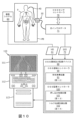
図2を参照すると、本開示の発明は、1つ又は複数の解剖学的領域(例えば、心血管系の心臓及び血管、呼吸器系の気道及び肺、消化器系の胃及び腸、並びに筋骨格系内の空洞)内の介入デバイス40のナビゲーションを伴う介入手順の実行のための介入デバイス40を構成するために、OSSセンサ20と1つ又は複数の介入ツール30との統合41を前提としている。
Referring to FIG. 2, the presently disclosed invention can be used to analyze one or more anatomical regions (e.g., the heart and blood vessels of the cardiovascular system, the airways and lungs of the respiratory system, the stomach and intestines of the digestive system, and the musculoskeletal system). Given the
介入ツール30の例は、限定はしないが、血管介入ツール(例えば、ガイドワイヤ、カテーテル、ステントシース、バルーン、アテローム切除カテーテル、IVUSイメージングプローブ、展開システムなど)、管腔内介入ツール(例えば、内視鏡、気管支鏡など)、及び整形外科的介入ツール(例えば、kワイヤ及びねじ回し)を含む。
Examples of
実際には、OSSセンサ20と介入ツール30との統合は、特定の介入手順に適した任意の構成である。
In practice, the integration of
さらに実際には、介入デバイス40の近位デバイスノード42pは、OSSセンサ20の近位OSSノード22pである。代替的には、介入デバイス40の近位デバイスノード42pは、本開示の技術分野で知られているように、近位OSSノード22pと近位ツールノード32pとの間の機械的関係マッピング又は形状テンプレートベースのマッピングを介してOSSセンサ20の近位OSSノード22pにマッピングされた近位ツールノード32pである。
Further in practice,
同様に、実際には、介入デバイス40の遠位デバイスノード42dは、OSSセンサ20の遠位OSSノード22dである。代替的には、介入デバイス40の遠位デバイスノード42dは、本開示の技術分野で知られているように、遠位OSSノード22dと遠位ツールノード32dとの間の機械的関係マッピング又は形状テンプレートベースのマッピングを介してOSSセンサ20の遠位OSSノード22dにマッピングされた遠位ツールノード32dである。
Similarly,
例えば、図3Aは、本開示の技術分野で知られているように、OSSガイドワイヤ40aの形態の介入デバイス40を構成するためにガイドワイヤ30a内に軸方向に埋め込まれたOSSセンサ20を示し、図3Bは、本開示の技術分野で知られているように、OSSガイドワイヤ40bの形態の介入デバイス40を構成するためにガイドワイヤ30b内に非軸方向に埋め込まれたOSSセンサ20を示す。OSSガイドワイヤ40a及びOSSガイドワイヤ40bは、ガイドワイヤの利用を伴う任意の介入手順に組み込まれ、それによって、OSSガイドワイヤ40a及びOSSガイドワイヤ40bは、本開示の技術分野で知られているように、OSSセンサ20の形状再構成機能を介して解剖学的領域内で必要に応じてナビゲートされる。
For example, FIG. 3A shows an
さらなる例によって、図4Aは、本開示の技術分野で知られているように、ユニバーサルカテーテル40cの形態の介入デバイス40を構成するためにカテーテル30cのチャネル内に一時的又は永続的に挿入されたOSSセンサ20を示し、図4Bは、本開示の技術分野で知られているように、ユニバーサルカテーテル40dの形態の介入デバイス40を構成するためにカテーテル30cのチャネル内に一時的又は永続的に挿入されたOSSガイドワイヤ40b(図3B)を示す。ユニバーサルカテーテル40c及びユニバーサルカテーテル40dは、カテーテル30cの作業チャネル31cの利用を伴う任意の介入手順に組み込まれ、それによって、ユニバーサルカテーテル40c及びユニバーサルカテーテル40dは、本開示の技術分野で知られているように、OSSセンサ20の形状再構成機能を介して解剖学的領域内で必要に応じてナビゲートされる。
By way of further example, FIG. 4A illustrates an
引き続き図4A及び図4Bを参照すると、ユニバーサルカテーテル40c及びユニバーサルカテーテル40dは、本開示の技術分野で知られているように、解剖学的領域内のユニバーサルカテーテル40c及びユニバーサルカテーテル40dのナビゲーションを容易にするためのハブ50をさらに用いる。本開示でさらに説明するように、実際には、ハブ50は、本開示の発明原理による、ハブ50に取り付けられた介入デバイスのOSS監視の視覚的フィードバックを提供するための発光ダイオード51、本開示の発明原理による、ハブ50に取り付けられた介入デバイスのOSS監視の触覚的フィードバックを提供するための振動モータ52、及び/又は本開示の発明原理による、ハブ50に取り付けられた介入デバイスのトルク伝達性メトリックの生成を容易にするための配向テンプレート53を含む。
With continued reference to FIGS. 4A and 4B,
図2に戻って参照すると、近位OSSノード22pは、OSSセンサ20の近位端21p内に位置するように示されており、遠位OSSノード22dは、OSSセンサ20の遠位端21d内に位置するように示されているが、実際には、近位OSSノード22p及び遠位OSSノード22dは、遠位OSSノード22dの位置よりもOSSセンサ20の近位端21pに近い近位OSSノード22pの位置によってのみ制限されるOSSセンサ20の構成内のどこにでも配置される。
Referring back to FIG. 2,
同様に、近位ツールノード32pは、介入ツール30の近位端31p内に位置するように示されており、遠位ツールノード32dは、介入ツール30の遠位端31d内に位置するように示されているが、実際には、近位ツールノード32p及び遠位ツールノード32dは、遠位ツールノード32dの位置よりも介入ツール30の近位端31pに近い近位ツールノード32pの位置によってのみ制限される介入ツール30の構成内のどこにでも配置される。
Similarly,
より具体的には、図3A及び図3Bを参照すると、介入ツール40aと介入ツール40bの両方は、特定の介入手順のために指定された近位端21p/31pと遠位端21d/31dとの間に位置する近位デバイスノード(図示せず)(例えば、図2の近位デバイスノード41p)と遠位デバイスノード(図示せず)(例えば、図2の遠位デバイスノード41)とを有する。例えば、近位デバイスノードは、介在デバイス40aの近位起点に又はそれに隣接して配置され、遠位デバイスノードは、介在デバイス40aの遠位先端に又はそれに隣接して配置される。同様に、近位デバイスノードは、介在デバイス40bの近位起点に又はそれに隣接して配置され、遠位デバイスノードは、介在デバイス40bの遠位先端に又はそれに隣接して配置される。
More specifically, referring to FIGS. 3A and 3B, both
さらに、図4A及び図4Bを参照すると、ユニバーサルカテーテル40cとユニバーサルカテーテル40dの両方は、特定の介入手順のために指定された近位端21p/31pと遠位端21d/31dとの間に位置する近位デバイスノード(図示せず)(例えば、図2の近位デバイスノード41p)と遠位デバイスノード(図示せず)(例えば、図2の遠位デバイスノード41)とを有する。例えば、近位デバイスノードは、ユニバーサルカテーテル40cのハブ50に又はそれに隣接して配置され、遠位デバイスノードは、ユニバーサルカテーテル40cの遠位先端に又はそれに隣接して配置される。同様に、近位デバイスノードは、ユニバーサルカテーテル40dのハブ50に又はそれに隣接して配置され、遠位デバイスノードは、ユニバーサルカテーテル40dの遠位先端に又はそれに隣接して配置される。
4A and 4B, both
本開示の発明のさらなる理解を容易にするために、図5A~図9Bの以下の説明は、本開示の発明原理による、それぞれの押し込み性メトリック及びトルク伝達性メトリックを介して解剖学的内腔AL内の介入デバイス40のそのような折れ曲がり及びねじれの監視のその後の教示を支持して本開示の技術分野で知られているように、解剖学的内腔AL内の介入デバイス40(図2)の折れ曲がり及びねじれを教示する。図5A~図9Bの実例は、解剖学的内腔AL内の介入デバイス40の折れ曲がり及びねじれの本明細書での説明を単純化する目的で、真っ直ぐな解剖学的内腔AL内の比較的短い介入デバイス40の折れ曲がり及びねじれのものであるが、当業者は、実際には、非常に細長い介入デバイス40が曲がりくねった解剖学的内腔ALを通ってナビゲートされ、それは、解剖学的内腔AL内の介入デバイス40の折れ曲がり及び/又はねじれの可能性を高めることを認識するであろう。
To facilitate a further understanding of the inventions of the present disclosure, the following description of FIGS. 5A-9B will provide an anatomical lumen via respective pushability and torquability metrics in accordance with the inventive principles of the present disclosure.
図5A~図9Bのこの説明から、当業者は、任意の解剖学的領域内の介入デバイス40の折れ曲がり及び/又はねじれの非常に高い可能性を理解するであろう。
From this description of FIGS. 5A-9B, those skilled in the art will appreciate the great potential for bending and/or twisting of
図5A~図9Bに示す本開示の構成要素は、縮尺通りに描かれておらず、本開示の発明原理を概念的にサポートするように描かれていることに留意されたい。 Note that the components of the present disclosure shown in FIGS. 5A-9B are not drawn to scale, but are drawn to conceptually support the inventive principles of the present disclosure.
図面に関して、図5A~図5Cは、介入デバイス40の近位セグメントが解剖学的内腔ALに無関係に前進するときに、近位デバイスノード42pと遠位デバイスノード42dとの間の介入デバイス40のいかなる折れ曲がりもいかなるねじれも伴わない距離D1及び距離D2にわたる解剖学的内腔ALを通る介入デバイス40の例示的なナビゲーションを示す。本開示の発明原理によれば、押し込み性メトリックは、近位デバイスノード42pと遠位デバイスノード42dとの間の介入デバイス40の非折れ曲がりの指標を提供し、トルク伝達性メトリックは、近位デバイスノード42pと遠位デバイスノード42dとの間の介入デバイス40の非ねじれの指標を提供する。
5A-5C illustrate
図6A~図6Cは、介入デバイス40の近位セグメントが解剖学的内腔ALに無関係に前進するときに、近位デバイスノード42pと遠位デバイスノード42dとの間の介入デバイス40の折れ曲がりを伴う距離D1及び距離D2にわたる解剖学的内腔ALを通る介入デバイス40の例示的な折れ曲がり、非ねじれナビゲーションを示す。本開示の発明原理によれば、押し込み性メトリックは、近位デバイスノード42pと遠位デバイスノード42dとの間の介入デバイス40の折れ曲がり/座屈の指標を提供し、トルク伝達性メトリックは、近位デバイスノード42pと遠位デバイスノード42dとの間の介入デバイス40の非ねじれの指標を提供する。
6A-6C illustrate the bending of
本開示の発明原理によれば、折れ曲がり(非座屈)閾値は、押し込み性メトリックに適用され、それによって、押し込み性メトリックが折れ曲がり閾値を超えた場合、解剖学的内腔ALを通して介入デバイス40をナビゲートするオペレータ又はロボットに解剖学的内腔AL内の介入デバイス40の折れ曲がりの警告が通信され、それによって、解剖学的内腔AL内の介入デバイス40の潜在的な座屈(例えば、図6Bの介入ツールの折れ曲がり)についてオペレータ又はロボットに警告する。したがって、折れ曲がり警告から、オペレータ又はロボットは、解剖学的内腔AL内の介入デバイス40を折り曲げない程度まで解剖学的内腔AL内の介入デバイス40を後退させる。
In accordance with the inventive principles of the present disclosure, a flexion (non-buckling) threshold is applied to the pushability metric such that if the pushability metric exceeds the flexion threshold, the
代替的に又は同時に、座屈閾値が押し込み性メトリックに適用され、それによって、押し込み性メトリックが座屈閾値を超えた場合、解剖学的内腔ALを通して介入デバイス40をナビゲートするオペレータ又はロボットに解剖学的内腔AL内の介入デバイス40の座屈(例えば、図6Cの介入ツールの座屈)の警告が通信される。座屈警告から、オペレータ又はロボットは、解剖学的内腔AL内の介入デバイス40の後退が絶対必要であることを理解し、それによって解剖学的内腔AL内の介入デバイス40の座屈を元に戻すか、又は介入デバイス40を交換する。
Alternatively or simultaneously, a buckling threshold is applied to the pushability metric, whereby if the pushability metric exceeds the buckling threshold, an operator or robot navigating the
図7A~図7Cは、介入デバイス40の近位セグメントが解剖学的内腔ALに無関係に前進するときに、近位デバイスノード42pと遠位デバイスノード42dとの間の介入デバイス40の折れ曲がりを伴う距離D1及び距離D2にわたる解剖学的内腔ALを通る介入デバイス40の別の例示的な折れ曲がり、非ねじれナビゲーションを示す。本開示の発明原理によれば、押し込み性メトリックは、近位デバイスノード42pと遠位デバイスノード42dとの間の介入デバイス40の折れ曲がり又は座屈の指標を提供し、トルク伝達性メトリックは、近位デバイスノード42pと遠位デバイスノード42dとの間の介入デバイス40の非ねじれの指標を提供する。折れ曲がり警告に応答して、オペレータ又はロボットは、折れ曲がり警告を無効にする程度まで介入デバイス40を解剖学的内腔ALから後退させる。
7A-7C illustrate the bending of
再び、本開示の発明原理によれば、折れ曲がり(非座屈)閾値は、押し込み性メトリックに適用され、それによって、押し込み性メトリックが折れ曲がり閾値を超えた場合、解剖学的内腔ALを通して介入デバイス40をナビゲートするオペレータ又はロボットに解剖学的内腔AL内の介入デバイス40の折れ曲がりの警告が通信され、それによって、解剖学的内腔AL内の介入デバイス40の潜在的な座屈(例えば、図7Bの介入ツールの折れ曲がり)についてオペレータ又はロボットに警告する。したがって、折れ曲がり警告から、オペレータ又はロボットは、解剖学的内腔AL内の介入デバイス40を折り曲げない程度まで解剖学的内腔AL内の介入デバイス40を後退させる。
Again, according to the inventive principles of the present disclosure, a kinking (non-buckling) threshold is applied to the pushability metric such that if the pushability metric exceeds the kinking threshold, the interventional device is pushed through the anatomical lumen AL. An operator or robot navigating 40 is alerted of the kinking of
代替的に又は同時に、座屈閾値が押し込み性メトリックに適用され、それによって、押し込み性メトリックが座屈閾値を超えた場合、解剖学的内腔ALを通して介入デバイス40をナビゲートするオペレータ又はロボットに解剖学的内腔AL内の介入デバイス40の座屈(例えば、図7Cの介入ツールの座屈)の警告が通信される。座屈警告から、オペレータ又はロボットは、解剖学的内腔AL内の介入デバイス40の後退が絶対必要であることを理解し、それによって解剖学的内腔AL内の介入デバイス40の座屈を元に戻すか、又は介入デバイス40を交換する。
Alternatively or simultaneously, a buckling threshold is applied to the pushability metric, whereby if the pushability metric exceeds the buckling threshold, an operator or robot navigating the
図8Aは、近位デバイスノード42p及び遠位デバイスノード42dの同期回転を伴う解剖学的内腔AL内の介入デバイス40の例示的な非ねじれ回転を示す。
FIG. 8A shows an exemplary non-torsional rotation of
図8B及び図8Cは、介入デバイス40の近位セグメントが解剖学的内腔ALに無関係に回転するときに、近位デバイスノード42pと遠位デバイスノード42dとの間の介入デバイス40のねじれを伴う解剖学的内腔AL内の介入デバイス40の例示的な非折れ曲がり、ねじれ回転を示す。より具体的には、図8Bは、解剖学的内腔ALに無関係な近位デバイスノード42pの回転と、図8Cに示すように解剖学的内腔AL内の遠位デバイスノード42dのしなりを最終的にもたらす解剖学的内腔AL内の遠位デバイスノード42dの非回転(又は最小)回転とを示す。本開示の発明原理によれば、押し込み性メトリックは、近位デバイスノード42pと遠位デバイスノード42dとの間の介入デバイス40の非折れ曲がりの指標を提供し、トルク伝達性メトリックは、近位デバイスノード42pと遠位デバイスノード42dとの間の介入デバイス40のねじれ又はしなりの指標を提供する。
8B and 8C illustrate twisting of
本開示の発明原理によれば、ねじれ(非しなり)閾値は、トルク伝達性メトリックに適用され、それによって、トルク伝達性メトリックがねじれ閾値を超えた場合、解剖学的内腔ALを通して介入デバイス40をナビゲートするオペレータ又はロボットに解剖学的内腔AL内の介入デバイス40のねじれの警告が通信され、それによって、解剖学的内腔AL内の介入デバイス40の潜在的なしなり(例えば、図8Bの介入ツールのねじれ)についてオペレータ又はロボットに警告する。したがって、ねじれ警告から、オペレータ又はロボットは、解剖学的内腔ALに無関係な介入デバイス40の近位セグメントを、解剖学的内腔AL内の介入デバイス40をねじらない程度まで反対方向に回転させる。
According to the inventive principles of the present disclosure, a torsion (non-bending) threshold is applied to the torqueability metric such that if the torqueability metric exceeds the torsion threshold, the interventional device is delivered through the anatomical lumen AL. A warning of twisting of the
代替的に又は同時に、しなり閾値がトルク伝達性メトリックに適用され、それによって、トルク伝達性メトリックがしなり閾値を超えた場合、解剖学的内腔ALを通して介入デバイス40をナビゲートするオペレータ又はロボットに解剖学的内腔AL内の介入デバイス40の可能性の高いしなり(例えば、図8Cの介入ツールのしなり)の警告が通信される。しなり警告から、オペレータ又はロボットは、解剖学的内腔AL内の介入デバイス40の逆回転が絶対必要であることを理解し、それによって解剖学的内腔AL内の介入デバイス40のいかなるしなりも防ぐ。
Alternatively or simultaneously, a flex threshold is applied to the torqueability metric, whereby an operator navigating the
図9Aは、近位デバイスノード42p及び遠位デバイスノード42dのゼロ回転を伴う解剖学的内腔AL内の介入デバイス40の例示的な非ねじれナビゲーションを示す。
FIG. 9A shows exemplary non-torsional navigation of
図9B及び図9Cは、介入デバイス40の近位セグメントが解剖学的内腔ALに無関係に前進するときに、近位デバイスノード42pと遠位デバイスノード42dとの間の介入デバイス40のねじれを伴う距離D1及び距離D2にわたる解剖学的内腔ALを通る介入デバイス40の別の例示的な非折れ曲がり、ねじれナビゲーションを示す。より具体的には、図9Bは、解剖学的内腔ALに無関係な近位デバイスノード42pの非回転(又は最小)回転と、図8Cに示すように解剖学的内腔内の遠位デバイスノード42dのしなりを最終的にもたらす、遠位デバイスノードが42d解剖学的内腔AL内で前進するときの(解剖学的内腔AL内の力による)解剖学的内腔AL内の遠位デバイスノード42dの回転とを示す。本開示の発明原理によれば、押し込み性メトリックは、近位デバイスノード42pと遠位デバイスノード42dとの間の介入デバイス40の非折れ曲がりの指標を提供し、トルク伝達性メトリックは、近位デバイスノード42pと遠位デバイスノード42dとの間の介入デバイス40のねじれの指標を提供する。
9B and 9C illustrate twisting of
再び、本開示の発明原理によれば、ねじれ(非しなり)閾値は、トルク伝達性メトリックに適用され、それによって、トルク伝達性メトリックがねじれ閾値を超えた場合、解剖学的内腔ALを通して介入デバイス40をナビゲートするオペレータ又はロボットに解剖学的内腔AL内の介入デバイス40のねじれの警告が通信され、それによって、解剖学的内腔AL内の介入デバイス40の潜在的なしなり(例えば、図9Bの介入ツールのねじれ)についてオペレータ又はロボットに警告する。したがって、ねじれ警告から、オペレータ又はロボットは、解剖学的内腔ALに無関係な介入デバイス40の近位セグメントを、解剖学的内腔AL内の介入デバイス40をねじらない程度まで反対方向に回転させる。
Again, according to the inventive principles of the present disclosure, a torsion (non-bending) threshold is applied to the torqueability metric such that if the torqueability metric exceeds the torsion threshold, A warning of twisting of the
代替的に又は同時に、しなり閾値がトルク伝達性メトリックに適用され、それによって、トルク伝達性メトリックがしなり閾値を超えた場合、解剖学的内腔ALを通して介入デバイス40をナビゲートするオペレータ又はロボットに解剖学的内腔AL内の介入デバイス40のしなり(例えば、図9Cの介入ツールのしなり)の警告が通信される。しなり警告から、オペレータ又はロボットは、解剖学的内腔AL内の介入デバイス40の逆回転が絶対必要であることを理解し、それによって解剖学的内腔AL内の介入デバイス40のいかなるしなりも防ぐ。
Alternatively or simultaneously, a flex threshold is applied to the torqueability metric, whereby an operator navigating the
図5A~図9Bでは、近位デバイスノード42pは、介入デバイス40の近位起点に位置し、遠位デバイスノード42dは、介入デバイス40の遠位先端に位置する。それにもかかわらず、本開示による押し込み性検出及びトルク伝達性検出の実施では、近位デバイスノード42p及び遠位デバイスノード42dは、遠位デバイスノード42dの前方にある近位デバイスノード42pと、解剖学的内腔内でナビゲートされるように指定された介入ツール40のセグメントを有する遠位デバイスノード42dとによってのみ制限される介入ツール40の構成内のどこにでも配置される。
5A-9B,
本開示の発明のさらなる理解を容易にするために、図10~図12の以下の説明は、介入デバイスが解剖学的領域内の介入デバイスの線形的/曲線的並進によって及び/又は解剖学的領域内の介入デバイスの軸方向/非軸方向回転によって解剖学的領域内をナビゲートされるときに、介入ツールとOSSセンサとの統合を含む介入デバイスの任意の折れ曲がり及び/又は任意のねじれを検出するためのOSS誘導及び監視システム、コントローラ、及び方法の基本的な発明原理を教示する。図10~図12のこの説明から、当業者は、本開示の発明原理に従ってOSS誘導及び監視システム、コントローラ、及び方法の多数の様々な実施形態を実施するために本開示の発明原理を適用する方法を認識するであろう。 To facilitate a further understanding of the inventions of the present disclosure, the following description of FIGS. 10-12 provides an explanation of how the interventional device may be anatomically controlled by linear/curvilinear translation of the interventional device within an anatomical region and/or anatomically. Any bending and/or twisting of the interventional device, including the integration of interventional tools and OSS sensors, as navigated within the anatomical region by axial/non-axial rotation of the interventional device within the region Basic inventive principles of OSS guidance and monitoring systems, controllers and methods for detection are taught. 10-12, one skilled in the art will apply the inventive principles of the present disclosure to implement many different embodiments of OSS guidance and monitoring systems, controllers, and methods in accordance with the inventive principles of the present disclosure. will know how.
図10を参照すると、本開示のOSS誘導及び監視システムは、介入デバイス40(図2)と、撮像システム60と、ワークステーション110上にインストールされたOSS誘導コントローラ90及びOSS監視コントローラ100を含むOSS誘導及び監視デバイス80とを用いる。OSS誘導及び監視システムは、患者のベッドPB上にうつ伏せに又は別のやり方で横たわる患者Pの解剖学的領域(例えば、心血管系の心臓及び血管、呼吸器系の気道及び肺、消化器系の胃及び腸、並びに筋骨格系内の空洞)内の介入デバイス40の任意の折れ曲がり及び任意のねじれの検出を提供する。
10, the OSS guidance and monitoring system of the present disclosure includes intervention device 40 (FIG. 2),
実際には、介入デバイス40は、図1~図4Bに関連して本開示で前述したように、介入OSSセンサ20と1つ又は複数の介入ツール30との統合を含む。例えば、介入デバイス40は、OSSガイドワイヤ40a(図3A)、OSSガイドワイヤ40b(図3B)、ユニバーサルカテーテル40c(図4A)、及びユニバーサルカテーテル40d(図4B)である。
In practice, the
実際には、撮像システム60は、患者Pの解剖学的領域のボリューム画像を生成するための任意のタイプの撮像モダリティ(例えば、X線システム、MRIシステム、CTシステム、超音波システムなど)を実施する。
In practice, the
実際には、OSS誘導コントローラ90及びOSS監視コントローラ100は、本開示の発明原理に従って患者Pの解剖学的領域内の介入デバイス40のナビゲーションを誘導し監視するためのハードウェア、ソフトウェア、ファームウェア、及び/又は電子回路の任意の配置を具体化する。
In practice,
一実施形態では、OSS誘導コントローラ90及びOSS監視コントローラ100は、1つ又は複数のシステムバスを介して相互接続されたプロセッサと、メモリと、ユーザインターフェースと、ネットワークインターフェースと、記憶装置とを含む。
In one embodiment,
プロセッサは、メモリ若しくは記憶装置内に記憶された命令を実行するか、又はデータを別のやり方で処理することが可能な、本開示の技術分野で知られているか、又は以下で考えられる任意のハードウェアデバイスである。非限定的な例では、プロセッサは、マイクロプロセッサ、フィールドプログラマブルゲートアレイ(FPGA)、特定用途向け集積回路(ASIC)、又は他の同様のデバイスを含む。 A processor is any device known in the art of this disclosure or contemplated below that is capable of executing instructions or otherwise processing data stored in a memory or storage device. It is a hardware device. In non-limiting examples, processors include microprocessors, field programmable gate arrays (FPGAs), application specific integrated circuits (ASICs), or other similar devices.
メモリは、限定はしないが、L1、L2、若しくはL3キャッシュ、又はシステムメモリを含む、本開示の技術分野で知られているか、又は以下で考えられる様々なメモリを含む。非限定的な例では、メモリは、スタティックランダムアクセスメモリ(SRAM)、ダイナミックRAM(DRAM)、フラッシュメモリ、読み取り専用メモリ(ROM)、又は他の同様のメモリデバイスを含む。 Memory includes various memories known in the art of this disclosure or contemplated below, including but not limited to L1, L2, or L3 caches, or system memory. In non-limiting examples, memory includes static random access memory (SRAM), dynamic RAM (DRAM), flash memory, read only memory (ROM), or other similar memory devices.
ユーザインターフェースは、管理者などのユーザとの通信を可能にするための、本開示の技術分野で知られているか、又は以下で考えられる1つ又は複数のデバイスを含む。非限定的な例では、ユーザインターフェースは、ネットワークインターフェースを介してリモート端末に提示されるコマンドラインインターフェース又はグラフィカルユーザインターフェースを含む。 The user interface includes one or more devices known in the technical field of this disclosure or contemplated below for enabling communication with a user, such as an administrator. In non-limiting examples, the user interface includes a command line interface or graphical user interface presented to the remote terminal via the network interface.
ネットワークインターフェースは、他のハードウェアデバイスとの通信を可能にするための、本開示の技術分野で知られているか、又は以下で考えられる1つ又は複数のデバイスを含む。非限定的な例では、ネットワークインターフェースは、イーサネット(登録商標)プロトコルに従って通信するように構成されたネットワークインターフェースカード(NIC)を含む。加えて、ネットワークインターフェースは、TCP/IPプロトコルに従って通信するためのTCP/IPスタックを実施する。ネットワークインターフェースのための様々な代替の又は追加のハードウェア又は構成が明らかである。 A network interface includes one or more devices known in the technical field of this disclosure or contemplated below for enabling communication with other hardware devices. In a non-limiting example, the network interface includes a network interface card (NIC) configured to communicate according to the Ethernet protocol. Additionally, the network interface implements a TCP/IP stack for communicating according to the TCP/IP protocol. Various alternative or additional hardware or configurations for network interfaces are apparent.
記憶装置は、限定はしないが、読み取り専用メモリ(ROM)、ランダムアクセスメモリ(RAM)、磁気ディスク記憶媒体、光記憶媒体、フラッシュメモリデバイス、又は同様の記憶媒体を含む、本開示の技術分野で知られているか、又は以下で考えられる1つ又は複数の機械可読記憶媒体を含む。様々な非限定的な実施形態では、記憶装置は、プロセッサによる実行のための命令、又はプロセッサが操作するデータを記憶する。例えば、記憶装置は、ハードウェアの様々な基本動作を制御するための基本オペレーティングシステムを記憶する。記憶装置は、実行可能なソフトウェア/ファームウェアの形態で1つ又は複数のアプリケーションモジュールをさらに記憶する。 Storage devices include, but are not limited to, read-only memory (ROM), random-access memory (RAM), magnetic disk storage media, optical storage media, flash memory devices, or similar storage media in the technical field of the present disclosure. including one or more machine-readable storage media known or hereinafter considered. In various non-limiting embodiments, the storage device stores instructions for execution by the processor or data on which the processor manipulates. For example, the storage device stores a base operating system for controlling various basic operations of the hardware. The storage device also stores one or more application modules in the form of executable software/firmware.
より具体的には、引き続き図10を参照すると、OSS誘導コントローラ90のアプリケーションモジュールは、本開示の技術分野で知られており、且つ本開示でさらに例示的に説明する形状感知データ72に応答して介入ツール40の形状を再構成するための形状再構成器91である。
More specifically, with continued reference to FIG. 10, the
さらに、OSS監視コントローラ100のアプリケーションモジュールは、本開示でさらに例示的に説明する本開示の発明原理に従って患者Pの解剖学的領域内の介入デバイス40の任意の折れ曲がりを検出するための押し込み性検出器101、及び/又は本開示でさらに例示的に説明する本開示の発明原理に従って患者Pの解剖学的領域内の介入デバイス40の任意のねじれを検出するためのトルク伝達性検出器102を含む。
In addition, the application module of the
実際には、OSS監視コントローラ100は、押し込み性検出器101及び/又はトルク伝達性検出器102を含む。
In practice, the OSS
引き続き図10を参照すると、ワークステーション110は、モニタ111、キーボード112、及びコンピュータ113の知られている配置を含む。
With continued reference to FIG. 10,
実際には、OSS誘導及び監視デバイス80は、代替的に又は同時に、限定はしないが、ワークステーション及びタブレットによってアクセス可能なタブレット若しくはサーバを含む他のタイプの処理デバイス上にインストールされ、又は、介入デバイス40を伴う介入手順の実行をサポートするネットワークを介して分散される。
In practice, the OSS guidance and
また、実際には、OSS誘導コントローラ90及びOSS監視コントローラ100は、OSS誘導及び監視デバイス80の統合された構成要素、分離された構成要素、又は論理的に分割された構成要素である。
Also, in practice,
引き続き図10を参照すると、動作中、撮像システム60は、患者Pの対象解剖学的領域のボリューム画像を表示するためのボリューム画像データVID61を手術前及び/又は手術中に生成する。ボリューム画像データVID61は、OSS誘導及び監視デバイス80に通信され(例えば、ボリューム画像データVID61のストリーミング又はアップロード)、それによって、OSS誘導コントローラ90は、本開示の技術分野で知られているように患者Pの解剖学的領域のボリューム画像上の介入デバイス40の再構成形状のオーバレイ表示を制御する。例えば、図10は、患者Pの血管系のボリューム画像上の介入デバイス40の再構成形状のモニタ111上のオーバレイ表示を示す。
With continued reference to FIG. 10, in operation,
代替的には、OSS誘導及び監視システムは、撮像システム60を省略し、それによって、介入デバイス40の再構成形状のみがモニタ111上に表示される。
Alternatively, the OSS guidance and monitoring system omits
介入デバイス40は、図示のように患者のベッドPBのレールに隣接するか、又は代替的には患者のベッドPB隣りのカート(図示せず)に隣接するか、又は代替的にはワークステーション(例えば、ワークステーション100又はタブレット(図示せず))に隣接するランチ51から遠位に延びる。光ファイバ50は、ランチ51から光インテロゲータ71まで近位に延びる。実際には、光ファイバ50は、ランチ51において介入デバイス40のOSSセンサ20に接続された別個の光ファイバ、又はランチ51を通って延びるOSSセンサ20の近位延長部である。
The
本開示の技術分野で知られているように、OSSセンサコントローラ70は、光インテロゲータ71による光ファイバ50を介するOSSセンサ20への光の周期的な放射を制御し、OSSセンサ20を介して介入デバイス40の遠位先端に伝播され、それによって、光は、固定基準位置として機能するランチ51に対する介入デバイス40の形状の情報を与える形状感知データ72をそれによって生成する。実際には、OSSセンサ20の遠位端は、特にOSSセンサ20の光反射性実施形態では閉じられるが、特にOSSセンサ20の光透過性実施形態では開かれる。
As is known in the art of this disclosure,
OSSセンサコントローラ70は、本開示の技術分野で知られているように、形状感知データ72の時間フレームシーケンスのOSS誘導コントローラ90への通信を制御する。より具体的には、各フレームは、OSSセンサ20の歪みセンサ(例えば、ファイバブラッググレーティング又はレイリー後方散乱)の単一の問合せサイクルからなり、それによって、形状再構成器91は、本開示の技術分野で知られているように時間フレーム単位でOSSセンサ20の形状を再構成し、それは、OSSセンサ20と介入デバイス30との特定の統合から導出された介入デバイス40の形状の再構成を提供する。
実際には、形状再構成器91は、本開示の技術分野で知られているように介入デバイス40の形状を再構成するための任意の再構成技法を実施する。
In practice, shape
一再構成実施形態では、形状再構成器91は、光インテロゲータ71に対応する座標系内で、時間フレーム単位で形状感知データ72を介して介入デバイス40の形状のポーズの描写を実行する。
In one reconstruction embodiment, the
第2の再構成実施形態では、形状再構成器91は、光インテロゲータ71の座標系の撮像システム60の座標系へのレジストレーションを実行し、それによって、形状再構成器91は、撮像システム60の座標系内で、時間フレーム単位で形状感知データ72を介して介入デバイス40の形状の描写を位置決めし方向付ける。例えば、図11A~図11Cは、図6A~図6Cに示す解剖学的内腔AL内の介在デバイス40の例示的なナビゲーションを含む時間フレーム単位での撮像システム60の座標系内の介入デバイス40の形状の再構成を示す。
In a second reconstruction embodiment, shape
図10に戻って参照すると、OSS誘導コントローラ90が介入デバイス40の再構成形状の表示を制御するとき、OSS監視コントローラ100は、図12に示すフローチャート120によって表されるように本開示のOSS監視方法を実施する。
Referring back to FIG. 10, when the
図12を参照すると、フローチャート120のステージS122は、介入ツール40の近位デバイスノード及び遠位デバイスノードの静的又は動的選択を実施するOSS監視コントローラ100を包含する。
Referring to FIG. 12, stage S122 of flowchart 120 involves OSS
実際には、OSS監視コントローラ100は、デバイスノードを介入デバイス40の単一の点、複数の点、セグメント、テンプレート(例えば、形状、湾曲、又は歪み)、又はそれ以外の任意の部分として選択するための、本開示の技術分野で知られている任意の技法を実施する。
In practice, OSS
ステージS122の一実施形態では、介入デバイス40及び撮像システム60のレジストレーションに続いて、グラフィカルユーザインターフェースがワークステーション110のオペレータに提供され、それによって、オペレータは、近位デバイスノードと遠位デバイスノードとを選択することが可能である。
In one embodiment of stage S122, following registration of
ステージS122の別の実施形態では、OSSセンサ20の遠位先端の又はそれに隣接する遠位OSSノードが、OSS監視コントローラ100によって遠位デバイスノードとして指定される。
In another embodiment of stage S122, a distal OSS node at or adjacent to the distal tip of
ステージS122の別の実施形態では、OSS監視コントローラ100は、(1)介入デバイス40のレジストレーション位置(例えば、ユニバーサルカテーテル位置)を使用するか、(2)(例えば、本開示の技術分野で知られているように、OSSセンサ20の把持による軸方向歪みにおいて測定された温度プロファイル又は湾曲のサインを介して)オペレータが介入デバイス40を保持している場所を識別するか、又は(3)(例えば、本開示の技術分野で知られているように、導入器の温度プロファイル及び/又は形状テンプレートを介して)介入デバイス40が患者Pの身体に入る場所を識別するかのいずれかによって、近位デバイスノードを指定する。
In another embodiment of stage S122,
OSS監視コントローラ100は、本開示の発明原理による押し込み性検出方法130の実行のために近位デバイスノード選択データ43a及び遠位デバイスノード選択データ43bを押し込み性検出器101に提供し、並びに/又は、本開示の発明原理によるトルク伝達性検出方法180の実行のために近位デバイスノード選択データ43a及び遠位デバイスノード選択データ43bをトルク伝達性検出器102に提供する。
より具体的には、押し込み性検出方法130に関して、押し込み性検出器101は、
1.患者Pの解剖学的領域内の介入ツール40の遠位デバイスノードの対応する前進なしの、解剖学的領域に無関係な介入ツール40の近位デバイスノードの前進、
2.介入デバイス40が患者Pの解剖学的領域内でナビゲートされるときの介入ツール40の近位デバイスノードと遠位デバイスノードとの間の介入ツール40の長手方向の湾曲の変化の領域、
3.介入デバイス40が患者Pの解剖学的領域内でナビゲートされるときの介入ツール40の遠位デバイスノードに対する過剰な力、及び/又は、
4.介入デバイス40が患者Pの解剖学的領域内でナビゲートされるときの介入ツール40による過度の横方向の動き
を検出することによって、時間フレーム単位で形状感知データ72(図10)を介して1つ又は複数の押し込み性メトリックを導出する。
More specifically, regarding the
1. advancement of a proximal device node of the
2. areas of change in longitudinal curvature of the
3. excessive force on the distal device node of the
4. By detecting excessive lateral movement by the
折れ曲がり/座屈警告目的のために、押し込み性検出器101は、それによって介入ツールが解剖学的領域内でさらに前進することができる介入デバイス40の折れ曲がりを描写する折れ曲がり(非座屈閾値)を超える非ゼロの大きさを有する押し込み性メトリック、及び/又は、それによって介入デバイス40が解剖学的領域内でさらに前進することができない介入デバイスの折れ曲がりを描写する座屈閾値を超える非ゼロの大きさを有する押し込み性メトリックに応答して、介入デバイス40の座屈の可能性を確認する。
For kink/buckling warning purposes, the
折れ曲がり警告及び/又は座屈警告は、
1.テキスト表示警告(例えば、表示される介入デバイスの形状再構成に重なるテキストの折れ曲がり/座屈メッセージ)、
2.聴覚警告(例えば、介入デバイスの折れ曲がり又は座屈を言葉で表す聴覚メッセージ)、
3.視覚表示警告(例えば、表示される介入デバイスの形状再構成の色分けされた折れ曲がり/座屈警告)、
4.視覚デバイス警告(例えば、介入デバイスのハブLEDの通電)、及び
5.触覚警告(例えば、介入デバイスのハブモータの振動)
によって、押し込み性検出器101によって通信される。
Bending and/or buckling warnings are
1. textual display warnings (e.g., textual bending/buckling messages overlaid on displayed interventional device shape reconstructions);
2. an audible warning (e.g., an audible message verbalizing the bending or buckling of the interventional device);
3. visual display warnings (e.g. color-coded bending/buckling warnings of interventional device shape reconstruction displayed);
4. 4. visual device alerts (eg, energizing hub LEDs on intervention devices); Tactile alerts (e.g. hub motor vibration of intervention devices)
is communicated by the
より具体的には、トルク伝達性検出方法180に関して、トルク伝達性検出器102は、
1.患者Pの解剖学的領域内のOSSセンサ20の遠位デバイスノードの対応する回転なしの、患者Pの解剖学的領域に無関係なOSSセンサ20の近位デバイスノードの回転、及び
2.介入デバイス40が患者Pの解剖学的領域内でナビゲートされるときのOSSセンサ20の近位デバイスノードとOSSセンサ20の遠位デバイスノードとの間のOSSセンサ20の軸方向回転の領域
を検出することによって、時間フレーム単位で形状感知データ72(図10)を介して1つ又は複数のトルク伝達性メトリックを導出する。
More specifically, with respect to
1. 2. Rotation of the proximal device node of the
ねじれ/しなり警告の目的のために、トルク伝達性検出器102は、非ゼロの大きさを有するか、若しくは解剖学的領域内の介入デバイス40のしなりの影響を受けにくい介入デバイスのねじれを描写するねじれ(非しなり)閾値を超えるトルク伝達性メトリック、及び/又は、解剖学的領域内の介入デバイスのしなりの影響を受けやすい介入デバイス40の描写されたねじれを示すしなり閾値を超える非ゼロの大きさを有するトルク伝達性メトリックに応答して、介入デバイス40のしなりの可能性を確認する。
For the purpose of torsion/bending warning, the
ねじれ警告及び/又はしなり警告は、
1.テキスト表示警告(例えば、表示される介入デバイスの形状再構成に重なるテキストのねじれ/しなりメッセージ)、
2.聴覚警告(例えば、介入デバイスのねじれ又はしなりを言葉で表す聴覚メッセージ)、
3.視覚表示警告(例えば、介入デバイスの表示される形状再構成の色分けされたねじれ/しなり警告)、
4.視覚デバイス警告(例えば、介入デバイスのハブLEDの通電)、及び
5.触覚警告(例えば、介入デバイスのハブモータの振動)
によって、トルク伝達性検出器101によって通信される。
Torsion warning and/or bending warning
1. textual display warnings (e.g., textual twist/bend messages overlaid on displayed interventional device shape reconstructions);
2. audible alerts (e.g., audible messages verbalizing twisting or flexing of interventional devices);
3. visual display warnings (e.g. color-coded twist/bending warnings of visible shape reconstruction of the interventional device);
4. 4. visual device alerts (eg, energizing hub LEDs on intervention devices); Tactile alerts (e.g. hub motor vibration of intervention devices)
is communicated by the
本開示の発明のさらなる理解を容易にするために、図13~図16の以下の説明は、本発明の発明原理による押し込み性検出方法及びトルク伝達性検出方法の実施形態を教示する。図13~図16のこの説明から、当業者は、本発明の発明原理による押し込み性検出方法及びトルク伝達性検出方法の多数の様々な実施形態を実施するために本開示の発明原理を適用する方法を認識するであろう。 To facilitate a further understanding of the invention of the present disclosure, the following descriptions of FIGS. 13-16 teach embodiments of the pushability detection method and the torqueability detection method according to the inventive principles of the present invention. From this description of FIGS. 13-16, those skilled in the art will apply the inventive principles of the present disclosure to implement many different embodiments of pushability detection methods and torqueability detection methods according to the inventive principles of the present invention. will know how.
図13Aを参照すると、フローチャート130aは、介入デバイス40(図10)の近位セグメントが解剖学的領域に手動で又はロボットで前進しているときに時間フレーム単位で押し込み性検出器101(図10)によって実行可能な押し込み性検出方法130(図12)の一実施形態を表す。 Referring to FIG. 13A, a flow chart 130a illustrates the intrusiveness detector 101 (FIG. 10) on a time frame basis as the proximal segment of the interventional device 40 (FIG. 10) is manually or robotically advanced into the anatomical region. ) represents an embodiment of a pushability detection method 130 (FIG. 12) that can be performed by .
フローチャート130aのステージS132aは、近位デバイスノードデータ43aによって示される近位デバイスノード及び遠位デバイスノードデータ43bによって示される遠位デバイスノードに対応する形状感知データ72(図10)の2つ以上のフレームに応答する押し込み性検出器101による前進押し込み性メトリックの初期生成を包含する。より具体的には、ステージS132aは、関連する座標系(例えば、インテロゲータ又は撮像)内の近位デバイスノードの並進ベクトルTVPSSN及び関連する座標系(例えば、インテロゲータ又は撮像)内の遠位デバイスノードの並進ベクトルTVDSSNの押し込み性検出器101による決定を伴い、それによって、押し込み性メトリックは、TVPSSN-TVDSSNに従って2つのベクトルの大きさの間の差になる。
Stage S132a of flow chart 130a consists of processing two or more pieces of shape sensing data 72 (FIG. 10) corresponding to a proximal device node indicated by proximal
フローチャート130aのステージS134aは、押し込み性メトリックへの折れ曲がり閾値の適用に基づく折れ曲がり警告の条件付きアクティブ化、及び/又は押し込み性メトリックへの座屈閾値の適用に基づく座屈警告の条件付きアクティブ化を包含する。より具体的には、折れ曲がり閾値は、介入デバイス40が解剖学的領域内でさらに前進することができる介入デバイスの折れ曲がりを描写し、及び/又は、座屈閾値は、介入ツールが解剖学的領域内をさらに前進することができない介入デバイス40の折れ曲がりを描写する。
Stage S134a of flowchart 130a performs conditional activation of a bend warning based on application of a bend threshold to the pushability metric and/or conditional activation of a buckling warning based on application of a buckling threshold to the pushability metric. contain. More specifically, the kinking threshold describes the flexing of the interventional device that allows the
実際には、折れ曲がり閾値及び/又は座屈閾値のいずれもが押し込み性検出器101によって実施される。
In practice, both the bending threshold and/or the buckling threshold are implemented by the
折れ曲がり閾値が押し込み性検出器101によって排他的に実施される場合、折れ曲がり閾値は、押し込み性メトリックが折れ曲がり閾値を超えたときに折れ曲がり警告がアクティブ化されるゼロよりも大きい任意の大きさである。折れ曲がり警告は、患者Pの解剖学的領域内の介入デバイス40の表示された再構成形状の色分け、テキスト表示警告、聴覚警告、視覚警告(例えば、介入デバイス40のハブLEDの通電)、及び/又は触覚フィードバック(例えば、介入デバイス40のハブモータの振動)を介して押し込み性検出器101によって通信される。
If the inflection threshold is implemented exclusively by the
実際には、折れ曲がり閾値の値は、機械学習から導出されるか、又は複数のテストシナリオから経験的に導出される。 In practice, the value of the kink threshold is derived from machine learning or empirically derived from multiple test scenarios.
同様に、座屈閾値が押し込み性検出器101によって排他的に実施される場合、座屈閾値は、押し込み性メトリックが座屈閾値を超えたときに座屈警告がアクティブ化されるゼロよりも大きい任意の大きさである。座屈警告は、患者Pの解剖学的領域内の介入デバイス40の表示された再構成形状の色分け、テキスト表示警告、聴覚警告、視覚警告(例えば、介入デバイス40のハブLEDの通電)、及び/又は触覚フィードバック(例えば、介入デバイス40のハブモータの振動)を介して押し込み性検出器101によって通信される。
Similarly, if the buckling threshold is enforced exclusively by the
実際には、座屈閾値の値は、機械学習から導出されるか、又は複数のテストシナリオから経験的に導出される。 In practice, the value of the buckling threshold is derived from machine learning or empirically derived from multiple test scenarios.
そうではなく、折れ曲がり閾値と座屈閾値との両方が押し込み性検出器101によって実施される場合、折れ曲がり閾値は、ゼロよりも大きく、座屈閾値の大きさよりも小さい大きさを有し、それによって、押し込み性メトリックが折れ曲がり閾値を超えるが、座屈閾値よりも小さいときに折れ曲がり警告がアクティブ化され、押し込み性メトリックが座屈閾値を超えたときに座屈警告がアクティブ化される。折れ曲がり警告及び座屈警告は、本開示で前述したように、各警告が特有のモードを有して押し込み性検出器101によって通信される。例えば、アクティブ化された折れ曲がり警告は、ハブLEDを定期的に通電し、アクティブ化された座屈警告は、ハブLEDを完全に通電する。また、例として、アクティブ化された折れ曲がり警告は、ハブモータを定期的に振動させ、アクティブ化された座屈警告は、ハブモータを連続的に振動させる。
Otherwise, if both the bending threshold and the buckling threshold are implemented by the
非アクティブ化警告シナリオの例が図5A~図5Cに示されている。 Examples of deactivation warning scenarios are shown in FIGS. 5A-5C.
アクティブ化警告シナリオの例が図6A~図6C及び図7A~図7Cに示されている。 Examples of activation alert scenarios are shown in FIGS. 6A-6C and 7A-7C.
引き続き図13Aを参照すると、フローチャート130aのステージS136aの間に押し込み性検出器101によって確認されるようにステージS134aの間に警告がアクティブ化されない場合、押し込み性検出器101は、近位デバイスノード及び遠位デバイスノードのフレームの次のセットを処理するためにステージS132aに戻る。
Continuing to refer to FIG. 13A, if the alert is not activated during stage S134a, as seen by
そうでない場合、ステージS136aの間に押し込み性検出器101によって確認されるようにステージS134aの間に警告がアクティブ化される場合、押し込み性検出器101は、関連する座標系(例えば、インテロゲータ又は撮像)内の近位デバイスノードの並進ベクトルTVPSSN、及び関連する座標系(例えば、インテロゲータ又は撮像)内の遠位デバイスノードの並進ベクトルTVDSSNの押し込み性検出器101による決定を包含するフローチャート130aのステージS138aに進み、それによって、押し込み性メトリックは、TVPSSN-TVDSSNに従って2つのベクトルの大きさの間の差になる。
Otherwise, if the alert is activated during stage S134a as seen by
近位デバイスノードの並進ベクトルTVPSSNの方向及び大きさが、近位デバイスノードが折れ曲がり閾値若しくは座屈閾値(アクティブ化された警告に適用可能な方)を超える程度まで解剖学的領域に対して後退したことを示すことを、押し込み性検出器101がフローチャート130aのステージS140aの間に確認した場合、又は、遠位デバイスノードの並進ベクトルTVDSSNの方向及び大きさが、遠位デバイスノードが折れ曲がり閾値若しくは座屈閾値(アクティブ化された警告に適用可能な方)を超える程度まで解剖学的領域内で前進したことを示すことを、押し込み性検出器101がステージS140の間に確認した場合、又は、押し込み性検出器101がステージS140の間に折れ曲がり閾値若しくは座屈閾値(アクティブ化された警告に適用可能な方)を超える近位後退及び遠位前進の任意の組合せを確認した場合、押し込み性検出器101は、アクティブ化された警告を非アクティブ化し、近位デバイスノード及び遠位デバイスノードのフレームの次のセットを処理するためにステージS132aに戻る。
The direction and magnitude of the translational vector TV PSSN of the proximal device node relative to the anatomical region to the extent that the proximal device node exceeds the bending or buckling threshold (whichever is applicable to the activated alert) If the
そうでない場合、押し込み性検出器101は、近位感知歪みノードが安全に後退し、及び/又は遠位感知歪みノードが安全に前進するそのようなときまで、近位デバイスノード及び遠位デバイスノードのフレームの次のセットを処理するためにステージS138aに戻る。
Otherwise, the
安全な近位感知歪みノードの後退の例が、逆の順序で図6A~図6C及び図7A~図7Cに示されている。 An example of safe proximal sensing strain node retraction is shown in reverse order in FIGS. 6A-6C and 7A-7C.
フローチャート130aの代替実施形態では、ステージS134aは、警告の追加の条件付きアクティブ化をさらに伴う。フローチャート130aのこの代替実施形態の一バージョンでは、前進押し込み性メトリックが適用可能な閾値を超えない(すなわち、遠位デバイスノードが近位デバイスノードとして対応する前進を行った)場合、押し込み性検出器101は、それにもかかわらず、遠位デバイスノードを含むOSSセンサ20の領域の形状がOSSセンサ20の形状、湾曲、又は歪み情報から導出される折れ曲がりテンプレート又は座屈テンプレート(例えば、C字型テンプレート又はZ字型テンプレート)の形態におけるテンプレート押し込み性メトリックに適合する場合、折れ曲がり/座屈警告をアクティブ化する。
In an alternative embodiment of flowchart 130a, stage S134a further involves additional conditional activation of the alert. In a version of this alternative embodiment of flowchart 130a, if the advance pushability metric does not exceed the applicable threshold (i.e., the distal device node made corresponding advance as the proximal device node), the
この代替実施形態の別のバージョンでは、前進押し込み性メトリックが適用可能な閾値を超えない(すなわち、遠位デバイスノードが近位デバイスノードとして対応する前進を行った)場合、押し込み性検出器101は、それにもかかわらず、介入ツール40の近位デバイスノードと遠位デバイスノードとの間のOSSセンサ20の任意の2つのOSSノード間の監視された空間的位置決めが真っ直ぐな整列でOSSセンサ20の隣接するOSSノードの構造的空間的位置決めから導出された空間的閾値よりも小さい場合、折れ曲がり/座屈警告をアクティブ化する。例えば、OSSセンサ20の隣接するOSSノードは、OSSセンサ20の任意の2つのOSSノードの監視された空間的位置決めYが空間的閾値Z(例えば、ミリメートルでの空間的距離)よりも小さい場合に折れ曲がり/座屈警告がアクティブ化されるXの構造的空間位置決め(例えば、センチメートルでの空間的距離)を有する。
In another version of this alternative embodiment, if the advance pushability metric does not exceed the applicable threshold (i.e., the distal device node made corresponding advance as the proximal device node), the
引き続き図13Aを参照すると、本開示の当業者は、フローチャート130aの利益が介入デバイス40の潜在的な又は可能性のある座屈の警告の体系的な条件付きアクティブ化であることを認識するであろう。
With continued reference to FIG. 13A, those skilled in the art of the present disclosure will appreciate that the benefit of flowchart 130a is the systematic conditional activation of warnings of potential or potential buckling of
例えば、図13Bは、解剖学的領域の入口位置における近位デバイスノードの例示的な並進ベクトルTVPSSNの時間グラフ150と、OSSセンサ20の遠位先端における遠位デバイスノードの例示的な並進ベクトルTVDSSNの時間グラフ表示151と、差分TVPSSN-TVDSSNである例示的な押し込み性メトリックの時間グラフとを示す。例示的な折れ曲がり閾値153及び/又は例示的な座屈閾値154は、介入デバイス40の潜在的な又は可能性のある座屈の警告の条件付きアクティブ化のための押し込み性メトリックに適用される。
For example, FIG. 13B shows a
図13Aに戻って参照すると、ステージS134a中の警告アクティブ化は、OSSセンサ20の隣接ノードの湾曲によって示されるOSSセンサ20の任意の折れ曲がり又は任意の座屈の位置の押し込み性検出器101による決定を伴う。
Referring back to FIG. 13A, alert activation during stage S134a is determined by
例えば、図14Aは、OSSセンサ20の遠位セグメントに沿ったOSSセンサ20の高い湾曲が図13Bに示す押し込み性メトリックのフレーム95の間のOSSセンサ20の検出された折れ曲がり及び/又は検出された座屈に対応する、最近位ノードから最遠位ノードまで延びるOSSセンサ20の湾曲のノードグラフ155を示す。この検出された折れ曲がり及び/又は検出された座屈は、例えば、図14Bに示すようにOSSセンサ20/介入デバイス40の再構成形状のプロット156を介する潜在的な座屈の例示的な識別によるなどして、OSSセンサ20/介入デバイス40の再構成形状のプロットを介してオペレータに通信される。
For example, FIG. 14A shows that high curvature of
実際には、OSSセンサ20によって感知される介入デバイス40の折れ曲がり/座屈の領域の位置は、その領域における介入デバイス40の形状の視覚化の変更(色分け、点滅、より太い形状視覚化など)によって、又は、形状全体を示し、座屈を有する領域を強調表示するモニタ画面の下部の小さいウィンドウによって(ユーザの視野が小さく、座屈がその領域内に発生する可能性が低い場合に有用)、又は、座屈の領域の上にオペレータを自動的にズームすることによって(ユーザがこのオプションを選択したときにも実行される)、又は、介入デバイス40の形状全体を視界から除去し、ユーザに警告を表示することによって、オペレータに通信される。
In practice, the position of the area of bending/buckling of the
図15を参照すると、フローチャート130bは、介入デバイス40(図10)の近位セグメントが解剖学的領域に手動で又はロボットで前進しているときに時間フレーム単位で押し込み性検出器101(図10)によって実行可能な押し込み性検出方法130(図12)の一実施形態を表す。 Referring to FIG. 15, a flow chart 130b illustrates the intrusiveness detector 101 (FIG. 10) on a time frame basis as the proximal segment of the interventional device 40 (FIG. 10) is manually or robotically advanced into the anatomical region. ) represents an embodiment of a pushability detection method 130 (FIG. 12) that can be performed by .
フローチャート130bのステージS132bは、近位デバイスノードデータ43aによって示される近位デバイスノードと遠位デバイスノードデータ43bによって示される遠位デバイスノードとに対応する形状感知データ72(図10)の2つのフレームに応答した押し込み性検出器101による湾曲押し込み性メトリックの初期生成を包含する。
Stage S132b of flow chart 130b generates two frames of shape sensing data 72 (FIG. 10) corresponding to a proximal device node indicated by proximal
一実施形態では、ステージS132bは、フレームごとの関連する座標系(例えば、インテロゲータ又は撮像)内の近位デバイスノードと遠位デバイスノードとの間の各デバイスノードの湾曲の押し込み性検出器101による決定を伴い、それによって、各ノードのノード湾曲押し込み性メトリックは、2つのフレームにわたる特定のノードの湾曲間の差である。
In one embodiment, stage S132b is determined by the
別の実施形態では、ステージS132bは、フレームごとの関連する座標系(例えば、インテロゲータ又は撮像)内の近位デバイスノードと遠位デバイスノードとの間の各デバイスノードの歪みの押し込み性検出器101による決定を伴い、それによって、各ノードの歪み湾曲押し込み性メトリックは、2つのフレームにわたる特定のノードの歪み間の差である。
In another embodiment, stage S132b performs
フローチャート130bのステージS134bは、押し込み性メトリック(ノード湾曲又は歪み湾曲)への折れ曲がり閾値の適用に基づく折れ曲がり警告の条件付きアクティブ化、及び/又は、押し込み性メトリック(ノード湾曲又は歪み湾曲)への座屈閾値の適用に基づく座屈警告の条件付きアクティブ化を包含する。より具体的には、折れ曲がり閾値は、介入デバイス40が解剖学的領域内でさらに前進することができる介入デバイスの折れ曲がりを描写し、及び/又は、座屈閾値指標は、介入ツールが解剖学的領域内でさらに前進することができない介入デバイス40の折れ曲がりを描写する。
Stage S134b of flowchart 130b includes conditional activation of a bend warning based on application of a bend threshold to the pushability metric (node bend or strain bend) and/or adjustment to the pushability metric (node bend or strain bend). Includes conditional activation of buckling warning based on application of a bending threshold. More specifically, the kinking threshold describes the flexing of the interventional device that allows the
実際には、折れ曲がり閾値及び/又は座屈閾値は、押し込み性検出器101によって実施される。
In practice, the bending and/or buckling thresholds are implemented by the
折れ曲がり閾値が押し込み性検出器101によって排他的に実施される場合、折れ曲がり閾値は、押し込み性メトリック(ノード湾曲又は歪み湾曲)が折れ曲がり閾値を超えたときに折れ曲がり警告がアクティブ化されるゼロよりも大きい任意の大きさである。折れ曲がり警告は、本明細書で前述したように、テキスト表示警告、聴覚表示警告、視覚表示警告(例えば、介入デバイス40の表示されたオーバレイの色分け)、視覚デバイス警告(例えば、介入デバイス40のハブLEDの通電)、及び/又は触覚デバイス警告(例えば、介入デバイス40のハブモータの振動)を介して押し込み性検出器101によって通信される。
If the inflection threshold is enforced exclusively by the
実際には、折れ曲がり閾値の値は、機械学習から、又は複数のテストシナリオから経験的に導出される。 In practice, the value of the kink threshold is derived empirically from machine learning or from multiple test scenarios.
同様に、座屈閾値が押し込み性検出器101によって排他的に実施される場合、座屈閾値は、(ノード湾曲又は歪み湾曲が)座屈閾値を超えたときに座屈警告がアクティブ化されるゼロよりも大きい任意の大きさである。座屈警告は、本明細書で前述したように、テキスト表示警告、聴覚表示警告、視覚表示警告(例えば、介入デバイス40の表示されたオーバレイの色分け)、視覚デバイス警告(例えば、介入デバイス40のハブLEDの通電)、及び/又は触覚デバイス警告(例えば、介入デバイス40のハブモータの振動)を介して押し込み性検出器101によって通信される。
Similarly, if the buckling threshold is enforced exclusively by the
実際には、座屈閾値の値は、機械学習から、又は複数のテストシナリオから経験的に導出される。 In practice, the buckling threshold value is derived empirically from machine learning or from multiple test scenarios.
そうではなく、折れ曲がり閾値と座屈閾値との両方が押し込み性検出器101によって実施される場合、折れ曲がり閾値は、ゼロよりも大きく、座屈閾値の大きさよりも小さい大きさを有し、それによって、(ノード湾曲又は歪み湾曲が)折れ曲がり閾値を超えるが、座屈閾値よりも小さいときに折れ曲がり警告がアクティブ化され、(ノード湾曲又は歪み湾曲が)座屈閾値を超えたときに座屈警告がアクティブ化される。折れ曲がり警告及び座屈警告は、本開示で前述したように、各警告が特有のモードを有して押し込み性検出器101によって通信される。例えば、アクティブ化された折れ曲がり警告は、ハブLEDを定期的に通電し、アクティブ化された座屈警告は、ハブLEDを完全に通電する。また、例として、アクティブ化された折れ曲がり警告は、ハブモータを定期的に振動させ、アクティブ化された座屈警告は、ハブモータを連続的に振動させる。
Otherwise, if both the bending threshold and the buckling threshold are implemented by the
非アクティブ化警告シナリオの例が図5A~図5Cに示されている。 Examples of deactivation warning scenarios are shown in FIGS. 5A-5C.
アクティブ化警告シナリオの例が図6A~図6C及び図7A~図7Cに示されている。 Examples of activation alert scenarios are shown in FIGS. 6A-6C and 7A-7C.
実際には、押し込み性メトリックがますます折れ曲がり閾値を超えるか、又は押し込み性メトリックが折れ曲がり閾値に近づくにつれて、折れ曲がり警告は、増加する強度及び増加する頻度でアクティブ化される。 In practice, as the indentability metric increasingly exceeds or approaches the indentation threshold, the indentation warning is activated with increasing intensity and increasing frequency.
また、実際には、押し込み性メトリックがますます座屈閾値を超えるか、又は押し込み性メトリックが座屈閾値に近づくにつれて、座屈警告は、増加する強度及び増加する頻度でアクティブ化される。 Also, in practice, the buckling warning is activated with increasing intensity and increasing frequency as the pushability metric increasingly exceeds or approaches the buckling threshold.
引き続き図15を参照すると、フローチャート130bのステージS136bの間に押し込み性検出器101によって確認されるようにステージS134bの間に警告がアクティブ化されない場合、押し込み性検出器101は、近位デバイスノード及び遠位デバイスノードのフレームの次のセットを処理するためにステージS132bに戻る。
Continuing to refer to FIG. 15, if the alert is not activated during stage S134b, as determined by the
そうでない場合、ステージS136bの間に押し込み性検出器101によって確認されるようにステージS134bの間に警告がアクティブ化される場合、押し込み性検出器101は、フローチャート130bのステージS138bに進む。
Otherwise, if the warning is activated during stage S134b as seen by
一実施形態では、ステージS138bは、フレームごとの関連する座標系(例えば、インテロゲータ又は撮像)内の近位デバイスノードと遠位デバイスノードとの間の各デバイスノードの湾曲の押し込み性検出器101による決定を伴い、それによって、各ノードのノード湾曲押し込み性メトリックは、2つのフレームにわたる特定のノードの湾曲間の差である。
In one embodiment, stage S138b is determined by the
別の実施形態では、ステージS138bは、フレームごとの関連する座標系(例えば、インテロゲータ又は撮像)内の近位デバイスノードと遠位デバイスノードとの間の各デバイスノードの歪みの押し込み性検出器101による決定を伴い、それによって、各ノードの歪み湾曲押し込み性メトリックは、2つのフレームにわたる特定のノードの歪み間の差である。
In another embodiment, stage S138b uses the
警告のアクティブ化を駆動する押し込み性メトリック(ノード湾曲又は歪み湾曲)が、近位デバイスノードが折れ曲がり閾値若しくは座屈閾値(アクティブ化された警告に適用可能な方)を超える程度まで解剖学的領域に対して後退したことを現在示していることを、押し込み性検出器101がフローチャート130bのステージS140bの間に確認した場合、又は、警告のアクティブ化を駆動する押し込み性メトリック(ノード湾曲又は歪み湾曲)が、遠位デバイスノードが折れ曲がり閾値若しくは座屈閾値(アクティブ化された警告に適用可能な方)を超える程度まで解剖学的領域内を前進したことを現在示していることを、押し込み性検出器101がステージS140の間に確認した場合、又は、押し込み性検出器101がステージS140の間に折れ曲がり閾値若しくは座屈閾値(アクティブ化された警告に適用可能な方)を超える近位後退及び遠位前進の任意の組合せを確認した場合、押し込み性検出器101は、アクティブ化された警告を非アクティブ化し、近位デバイスノードと遠位デバイスノードとの間のデバイスノードのフレームの次のセットを処理するためにステージS132bに戻る。
The anatomical region to the extent that the pushability metric (node curvature or strain curvature) that drives alert activation exceeds the kinking or buckling threshold (whichever is applicable for activated alerts) of the proximal device node or the indentation metric (node curvature or strain curvature ) currently indicates that the distal device node has advanced within the anatomical region to the extent that it exceeds the kinking or buckling threshold (whichever is applicable to the activated alert).
そうでない場合、押し込み性検出器101は、近位感知歪みノードが安全に後退し、及び/又は遠位感知歪みノードが安全に前進するそのようなときまで、近位デバイスノードと遠位デバイスノードとの間のデバイスノードのフレームの次のセットを処理するためにステージS138bに戻る。
Otherwise, the
安全な近位感知歪みノードの後退の例が、逆の順序で図6A~図6C及び図7A~図7Cに示されている。 An example of safe proximal sensing strain node retraction is shown in reverse order in FIGS. 6A-6C and 7A-7C.
フローチャート130bの代替実施形態では、ステージS134bは、警告の追加の条件付きアクティブ化をさらに伴う。具体的には、剛性の解剖学的領域内の介入デバイス40の折れ曲がり、特に座屈により、横方向の力及び摩擦力が解剖学的領域に加えられる。例えば、図16は、剛性の解剖学的内腔AL内の制約された経路171に限定される介入デバイス40の自然な機械的経路170を示す。
In an alternative embodiment of flowchart 130b, stage S134b further involves additional conditional activation of the alert. Specifically, bending, particularly buckling, of
そのような横方向の力及び摩擦力を検出するために、レジストレーションされたボリューム撮像データ61(図10)から経路湾曲押し込み性メトリックを導出する押し込み性検出器101を伴い、それによってステージS132bは、解剖学的領域を通る剛性経路を描写し、ステージS134bは、フレームごとに経路湾曲押し込み性メトリックを介入デバイス40の湾曲プロファイルと比較する押し込み性検出器1010を伴う。比較が、(例えば、本開示の技術分野で知られているように介入ツール40のスプライン補間を介して)解剖学的領域が解剖学的内腔を通る介入ツール40の自然な機械的経路を制約していることを示す場合、座屈警告がアクティブ化される。
To detect such lateral and frictional forces, involves an
図15に戻って参照すると、本開示の当業者は、フローチャート130bの利益が介入デバイス40の潜在的な又は可能性のある座屈の警告の体系的な条件付きアクティブ化であることを認識するであろう。
Referring back to FIG. 15, those skilled in the art of the present disclosure will appreciate that the benefit of flowchart 130b is the systematic conditional activation of warnings of potential or potential buckling of
図17Aを参照すると、フローチャート180aは、介入デバイス40(図10)の近位セグメントが手動又はロボットで解剖学的領域に対して回転するか又は解剖学的領域に前進するときに時間フレーム単位でトルク伝達性検出器102(図10)によって実行可能なトルク伝達性検出方法180(図12)の一実施形態を表す。 Referring to FIG. 17A, a flow chart 180a illustrates, on a time frame-by-time basis, when the proximal segment of interventional device 40 (FIG. 10) is manually or robotically rotated relative to or advanced into an anatomical region. 12 depicts one embodiment of a torqueability detection method 180 (FIG. 12) that can be performed by the torqueability detector 102 (FIG. 10).
フローチャート180aのステージS182aは、近位デバイスノードデータ43aによって示される近位デバイスノード及び遠位デバイスノードデータ43bによって示される遠位デバイスノードに対応する形状感知データ72(図10)の2つのフレームに応答するトルク伝達性検出器102によるトルク伝達性メトリックの初期生成を包含する。より具体的には、ステージS182aは、現在のフレームからの近位デバイスノード及び遠位デバイスノードのベースライン位置0°のトルク伝達性検出器102による設定と、それぞれのベースライン位置に対する近位デバイスノードの回転RPSSN及び遠位デバイスノードの回転RDSSNの決定とを伴い、それによって、トルク伝達性メトリックは、||RPSSN-RDSSN||の絶対値を有するノードの回転間の絶対差である。
Stage S182a of flowchart 180a divides two frames of shape sensing data 72 (FIG. 10) corresponding to the proximal device node indicated by proximal
フローチャート180aのステージS184aは、トルク伝達性メトリックへのねじれ閾値の適用に基づくねじれ警告の条件付きアクティブ化、及び/又はトルク伝達性メトリックへのしなり閾値の適用に基づくしなり警告の条件付きアクティブ化を包含する。より具体的には、解剖学的領域内の介入デバイス40のしなりの影響を受けにくい介入デバイスのねじれ、及び/又は、解剖学的領域内の介入デバイス40のしなりの影響を受けやすい介入デバイスの描写されたねじれを示すしなり閾値を超える非ゼロの大きさを有するトルク伝達性メトリックを描写する。
Stage S184a of flowchart 180a includes conditional activation of a torsion warning based on applying a torsion threshold to a torqueability metric and/or conditional activation of a flexing warning based on application of a flexing threshold to a torqueability metric. embrace transformation. More specifically, torsion of the interventional device less susceptible to flexing of the
実際には、ねじれ閾値及び/又はしなり閾値は、トルク伝達性検出器102によって実施される。
In practice, the torsion and/or bending thresholds are implemented by the
ねじれ閾値がトルク伝達性検出器102によって排他的に実施される場合、ねじれ閾値は、トルク伝達性メトリックがねじれ閾値を超えたときにねじれ警告がアクティブ化されるゼロよりも大きい任意の大きさである。ねじれ警告は、患者Pの解剖学的領域内の介入デバイス40の表示された再構成形状の色分け、テキスト表示警告、聴覚警告、視覚警告(例えば、介入デバイス40のハブLEDの通電)、及び/又は触覚フィードバック(例えば、介入デバイス40のハブモータの振動)を介してトルク伝達性検出器102によって通信される。
If the torsion threshold is implemented exclusively by the
実際には、ねじれ閾値の値は、機械学習から、又は複数のテストシナリオから経験的に導出される。 In practice, the value of the twist threshold is derived empirically from machine learning or from multiple test scenarios.
同様に、しなり閾値がトルク伝達性検出器102によって排他的に実施される場合、しなり閾値は、トルク伝達性メトリックがしなり閾値を超えたときにしなり警告がアクティブ化されるゼロよりも大きい任意の大きさである。しなり警告は、患者Pの解剖学的領域内の介入デバイス40の表示された再構成形状の色分け、テキスト表示警告、聴覚警告、視覚警告(例えば、介入デバイス40のハブLEDの通電)、及び/又は触覚フィードバック(例えば、介入デバイス40のハブモータの振動)を介してトルク伝達性検出器102によって通信される。
Similarly, if the flex threshold is implemented exclusively by the
実際には、しなり閾値の値は、機械学習から、又は複数のテストシナリオから経験的に導出される。 In practice, the bend threshold value is derived empirically from machine learning or from multiple test scenarios.
そうではなく、ねじれ閾値としなり閾値との両方がトルク伝達性検出器102によって実施される場合、ねじれ閾値は、ゼロよりも大きく、しなり閾値の大きさよりも小さい大きさを有し、それによって、トルク伝達性メトリックがねじれ閾値を超えるが、しなり閾値よりも小さいときにねじれ警告がアクティブ化され、トルク伝達性メトリックがしなり閾値を超えたときにしなり警告がアクティブ化される。ねじれ警告及びしなり警告は、本開示で前述したように、各警告が特有のモードを有してトルク伝達性検出器102によって通信される。例えば、アクティブ化されたねじれ警告は、ハブLEDを定期的に通電し、アクティブ化されたしなり警告は、ハブLEDを完全に通電する。また、例として、アクティブ化されたねじれ警告は、ハブモータを定期的に振動させ、アクティブ化されたしなり警告は、ハブモータを連続的に振動させる。
Otherwise, if both the torsion threshold and the bending threshold are implemented by the
非アクティブ化警告シナリオの例が図8A及び図9Aに示されている。 Examples of deactivation warning scenarios are shown in FIGS. 8A and 9A.
アクティブ化警告シナリオの例が図8B及び図9Bに示されている。 Examples of activation alert scenarios are shown in FIGS. 8B and 9B.
実際には、トルク伝達性メトリックがますますねじれ閾値を超えるか、又はトルク伝達性メトリックがねじれ閾値に近づくにつれて、ねじれ警告は、増加する強度及び増加する頻度でアクティブ化される。 In practice, as the torqueability metric increasingly exceeds or approaches the torsion threshold, the torsion warning is activated with increasing intensity and increasing frequency.
また、実際には、トルク伝達性メトリックがますますしなり閾値を超えるか、又はトルク伝達性メトリックがしなり閾値に近づくにつれて、しなり警告は、増加する強度及び増加する頻度でアクティブ化される。 Also, in practice, the flex warning is activated with increasing intensity and increasing frequency as the torqueability metric increasingly exceeds or approaches the flexion threshold. .
図17Aに戻って参照すると、フローチャート180aのステージS186aの間にトルク伝達性検出器102によって確認されるようにステージS184aの間に警告がアクティブ化されない場合、トルク伝達性検出器102は、ベースライン回転位置に対する近位デバイスノード及び遠位デバイスノードの次のフレームを処理するためにステージS182aに戻る。
Referring back to FIG. 17A, if the warning is not activated during stage S184a as determined by
そうではなく、ステージS186aの間にトルク伝達性検出器102によって確認されるようにステージS184aの間に警告がアクティブ化される場合、トルク伝達性検出器102は、トルク伝達性検出器102がそれぞれのベースライン位置に対する近位デバイスノードの回転RPSSN及び遠位デバイスノードの回転RDSSNの決定を継続するために次のフレームを処理することを包含するフローチャート180aのステージS188aに進み、それによって、トルク伝達性メトリックは、||RPSSN-RDSSN||の絶対値を有するノードの回転間の絶対差である。
Otherwise, if the warning is activated during stage S184a as determined by
トルク伝達性検出器102がフローチャート180aのステージS190aの間に、近位デバイスノード及び/又は遠位デバイスノードがねじれ閾値又はしなり閾値(アクティブ化された警告に適用可能な方)を超える程度まで展開されていることを確認した場合、トルク伝達性検出器102は、アクティブ化された警告を非アクティブ化し、ベースライン回転位置に対する近位デバイスノード及び遠位デバイスノードの次のフレームを処理するためにステージS182aに戻る。
To the extent that the
そうでない場合、トルク伝達性検出器102は、近位デバイスノード及び/若しくは遠位デバイスノードがねじれ閾値又はしなり閾値(アクティブ化された警告に適用可能な方)を超える程度まで展開されるまで、又は解剖学的領域内の介入デバイス40のしなりのトルク伝達性検出器102による検出時に、近位デバイスノード及び遠位デバイスノードの次のフレームを処理するためにステージS188aに戻る。
Otherwise, the
近位デバイスノード及び/又は遠位デバイスノードが展開されている場合、トルク伝達性検出器102は、ステージS182aに戻り、トルク伝達性メトリックを生成するための現在のベースライン位置を利用し続ける。
If the proximal and/or distal device nodes have been deployed, the
トルク伝達性検出器102が介入デバイス40のしなりを検出した場合、トルク伝達性検出器102は、ステージS182aに戻り、トルク伝達性メトリックを生成するためのベースライン位置をリセットする。
If the
しなりシナリオの例が図8C及び図9Cに示されている。 Examples of bending scenarios are shown in FIGS. 8C and 9C.
引き続き図17Aを参照すると、本開示の当業者は、フローチャート180aの利益が介入デバイス40の潜在的な又は可能性のあるしなりの警告の体系的な条件付きアクティブ化であることを認識するであろう。
With continued reference to FIG. 17A, those skilled in the art of the present disclosure will appreciate that the benefit of flowchart 180a is the systematic conditional activation of warnings of potential or potential flexing of
例えば、図17B及び17Cは、介入デバイス40の例示的なねじれのグラフ200と、ベースライン位置に対する近位デバイスノードに関連付けられた介入デバイス40のハブの例示的な回転のグラフ201と、ベースライン位置に対する遠位デバイスノードに関連付けられた介入デバイス40の遠位先端の例示的な回転のグラフ202と、ねじれ閾値204及びしなり閾値205(図17B)を有する例示的なトルク伝達性メトリックのグラフ203と、例示的なしなりインジケータのグラフ206とを示す。
For example, FIGS. 17B and 17C show
この例では、しなりは、フレーム200とフレーム250との間で発生し、それによって、トルク伝達性検出器102は、ベースライン位置をリセットする。
In this example, flex occurs between
図1~図17を参照すると、当業者は、限定はしないが、介入デバイスが解剖学的領域内で線形的/曲線的に並進する及び/又は軸方向/非軸方向に回転するときに、介入ツール及びOSSセンサの統合を組み込んだ介入デバイスの任意の折れ曲がり及び/又は任意のねじれの検出を提供する本開示の発明によるOSS誘導システム、コントローラ、及び方法の改善を含む、本開示の多数の利益を認識するであろう。 With reference to FIGS. 1-17, those skilled in the art will recognize, but are not limited to, that when an interventional device linearly/curvilinearly translates and/or axially/non-axially rotates within an anatomical region, Many of the present disclosure, including improvements in OSS guidance systems, controllers, and methods according to the disclosed inventions that provide detection of any flexing and/or any twisting of interventional devices that incorporate the integration of interventional tools and OSS sensors. will recognize the benefits.
さらに、当業者が本明細書で提供される教示を考慮して認識するように、本開示/明細書で説明する及び/又は図に示す特徴、要素、構成要素などは、電子構成要素/回路、ハードウェア、実行可能ソフトウェア、及び実行可能ファームウェアの様々な組合せで実施され、単一の要素又は複数の要素に結合される機能を提供する。例えば、図に示された/例示された/描かれた様々な特徴、要素、構成要素などの機能は、適切なソフトウェアに関連してソフトウェアを実行することができるハードウェアだけでなく、専用ハードウェアを使用して提供され得る。プロセッサによって提供される場合、機能は、単一の専用プロセッサによって、単一の共有プロセッサによって、又は、そのいくつかが共有及び/若しくは多重化される複数の個別のプロセッサによって提供され得る。さらに、「プロセッサ」という用語の明示的な使用は、ソフトウェアを実行することができるハードウェアを排他的に指すと解釈されるべきではなく、限定はしないが、デジタル信号プロセッサ(「DSP」)ハードウェア、メモリ(例えば、ソフトウェアを記憶するための読み取り専用メモリ(「ROM」)、ランダムアクセスメモリ(「RAM」)、不揮発性記憶装置など)、並びに、プロセスを実行及び/又は制御することができる(及び/又はそうするように構成可能な)実質的に任意の手段及び/又はマシン(ハードウェア、ソフトウェア、ファームウェア、回路、それらの組合せなどを含む)を暗に含み得る。 Furthermore, as those skilled in the art will appreciate in view of the teachings provided herein, the features, elements, components, etc. described and/or shown in this disclosure/specification are not electronic components/circuits. , may be implemented in various combinations of hardware, software executable, and firmware to provide functionality that may be combined in a single element or multiple elements. For example, the functionality of the various features, elements, components, etc. shown/illustrated/depicted in the figures may be represented by dedicated hardware as well as hardware capable of executing the software in conjunction with appropriate software. can be provided using ware. If provided by a processor, the functionality may be provided by a single dedicated processor, by a single shared processor, or by multiple separate processors, some of which are shared and/or multiplexed. Furthermore, any explicit use of the term "processor" should not be construed to refer exclusively to hardware capable of executing software, including, but not limited to, digital signal processor ("DSP") hardware software, memory (e.g., read-only memory (“ROM”), random-access memory (“RAM”), non-volatile storage, etc., for storing software), and can execute and/or control processes may implicitly include (and/or be configured to do) substantially any means and/or machine (including hardware, software, firmware, circuits, combinations thereof, etc.).
さらに、本発明の原理、態様、及び実施形態、並びにその特定の例を列挙する本明細書のすべての記述は、その構造的な均等物と機能的な均等物の両方を包含することを意図している。加えて、そのような均等物は、現在知られている均等物、並びに将来開発される均等物(例えば、構造に関係なく、同じ又は実質的に同様の機能を実行することができる任意の要素)の両方を含むことが意図されている。したがって、例えば、本明細書で提示される任意のブロック図は、本発明の発明原理を具体化する例示的なシステム構成要素及び/又は回路の概念図を表すことができることが、本明細書で提供される教示を考慮して当業者によって認識されるであろう。同様に、当業者は、本明細書で提供される教示を考慮して、任意のフローチャート、フロー図などが、コンピュータ可読記憶媒体内で実質的に表され得る、したがって、そのようなコンピュータ又はプロセッサが明示的に示されているかどうかにかかわらず、コンピュータ、プロセッサ、又は処理能力を有する他のデバイスによって実行され得る様々なプロセスを表すことができることを認識すべきである。 Moreover, all statements herein reciting principles, aspects, and embodiments of the invention, as well as specific examples thereof, are intended to encompass both structural and functional equivalents thereof. are doing. In addition, such equivalents include both now known equivalents as well as future developed equivalents (e.g., any element capable of performing the same or substantially similar functions, regardless of structure). ) are intended to include both Thus, for example, it is hereby understood that any block diagrams presented herein can represent conceptual views of illustrative system components and/or circuits embodying the inventive principles of the invention. It will be recognized by those skilled in the art in view of the teachings provided. Similarly, one of ordinary skill in the art, in view of the teachings provided herein, will appreciate that any flowchart, flow diagram, etc., can be substantially represented within a computer-readable storage medium, thus such a computer or processor , whether or not explicitly indicated, can represent various processes that can be performed by a computer, processor, or other device having processing capabilities.
さらに、本開示の例示的な実施形態は、例えば、コンピュータ又は任意の命令実行システムによって又はそれらに関連して使用するためのプログラムコード及び/又は命令を提供するコンピュータ使用可能及び/又はコンピュータ可読記憶媒体からアクセス可能なコンピュータプログラム製品又はアプリケーションモジュールの形態を取ることができる。本開示によれば、コンピュータ使用可能又はコンピュータ可読記憶媒体は、例えば、命令実行システム、装置、又はデバイスによって又はそれらに関連して使用するためのプログラムを含む、記憶する、通信する、伝播する、又は輸送することができる任意の装置であり得る。そのような例示的な媒体は、例えば、電子、磁気、光学、電磁気、赤外線、又は半導体システム(又は装置又はデバイス)又は伝播媒体であり得る。コンピュータ可読媒体の例は、例えば、半導体又は固体メモリ、磁気テープ、リムーバブルコンピュータディスケット、ランダムアクセスメモリ(RAM)、読み取り専用メモリ(ROM)、フラッシュ(ドライブ)、リジッド磁気ディスク、及び光ディスクを含む。光ディスクの現在の例は、コンパクトディスク-読み取り専用メモリ(CD-ROM)、コンパクトディスク-読み取り/書き込み(CD-R/W)、及びDVDを含む。さらに、今後開発される任意の新しいコンピュータ可読媒体も、本開示及び開示の例示的な実施形態に従って使用又は参照されるコンピュータ可読媒体とみなされるべきであることが理解されるべきである。 Further, the exemplary embodiments of the present disclosure are, for example, computer usable and/or computer readable storage that provides program code and/or instructions for use by or in connection with a computer or any instruction execution system. It can take the form of a computer program product or an application module accessible from a medium. According to this disclosure, a computer-usable or computer-readable storage medium contains, stores, communicates, propagates, e.g., a program for use by or in connection with an instruction execution system, apparatus, or device. or any device that can be transported. Such exemplary media can be, for example, electronic, magnetic, optical, electromagnetic, infrared, or semiconductor systems (or apparatus or devices) or propagation media. Examples of computer readable media include, for example, semiconductor or solid state memory, magnetic tape, removable computer diskettes, random access memory (RAM), read only memory (ROM), flash (drives), rigid magnetic disks, and optical disks. Current examples of optical discs include compact disc-read only memory (CD-ROM), compact disc-read/write (CD-R/W), and DVD. In addition, it should be understood that any new computer-readable medium developed in the future should be considered a computer-readable medium for use or reference in accordance with this disclosure and the illustrative embodiments of the disclosure.
新規で発明性のあるOSS誘導及び監視システム、コントローラ、及び方法の好ましい例示的な実施形態(これらの実施形態は、例示であり、限定するものではない)を説明したが、図を含む本明細書で提供される教示に照らして修正及び変形が当業者によってなされ得ることに留意されたい。したがって、本明細書で開示される実施形態の範囲内である本開示の好ましい例示的な実施形態において/に対して変更が行われ得ることが理解されるべきである。 Having described preferred exemplary embodiments of the novel and inventive OSS guidance and monitoring system, controller, and method (these embodiments are illustrative and not limiting), the present specification, including the figures, has been described. It should be noted that modifications and variations can be made by those skilled in the art in light of the teachings provided herein. It is therefore to be understood that changes may be made in/to the preferred exemplary embodiments of the present disclosure that are within the scope of the embodiments disclosed herein.
さらに、デバイスを組み込む及び/若しくは実施する対応する及び/若しくは関連するシステム、又は、本開示によるデバイスにおいて使用される/実施されるようなシステムも、本開示の範囲内であると考えられ、みなされると考えられる。さらに、本開示によるデバイス及び/又はシステムを製造及び/又は使用するための対応する及び/又は関連する方法も、本開示の範囲内であると考えられ、みなされる。
Additionally, corresponding and/or related systems incorporating and/or implementing the device, or systems as used/implemented in the device according to the present disclosure, are also contemplated and considered within the scope of the present disclosure. It is thought that In addition, corresponding and/or related methods for making and/or using devices and/or systems according to the present disclosure are also contemplated and considered within the scope of the present disclosure.
Claims (15)
前記介入デバイスが解剖学的領域内でナビゲートされるとき、前記OSSセンサが、前記OSSセンサの形状の情報を与える形状感知データを生成する、介入デバイスと、
OSS誘導及び監視デバイスとを備えるOSS誘導及び監視システムであって、前記OSS誘導及び監視デバイスが、
前記OSSセンサによる前記形状感知データの生成に基づいて前記解剖学的領域内の前記介入デバイスの形状の再構成を制御するOSS誘導コントローラと、
近位デバイスノードと遠位デバイスノードとの間の前記OSSセンサによる前記形状感知データの生成に基づいて押し込み性メトリック及びトルク伝達性メトリックのうちの少なくとも1つを生成することを含む、前記解剖学的領域内の前記介入デバイスの折れ曲がりの程度及びねじれの程度の監視を制御するOSS監視コントローラであって、
前記押し込み性メトリックが、時間フレーム単位で、前記近位デバイスノードの位置の変化の大きさと前記遠位デバイスノードの位置の変化の大きさとの比較により、前記介入デバイスの前記近位デバイスノードと前記遠位デバイスノードとの間の前記介入デバイスの推定される折れ曲がりの程度を定量化し、
前記トルク伝達性メトリックが、前記近位デバイスノード及び前記遠位デバイスノードのベースライン位置0°の設定と、当該ベースライン位置0°に対する前記近位デバイスノードの回転と前記遠位デバイスノードの回転との回転間の絶対差により、前記介入デバイスの前記近位デバイスノードと前記遠位デバイスノードとの間の前記介入デバイスの推定されるねじれの程度を定量化する、
OSS監視コントローラと
を含む、
OSS誘導及び監視システム。 An interventional device comprising an integration of an OSS sensor and at least one interventional tool, comprising:
an interventional device, wherein the OSS sensor generates shape sensing data that informs the shape of the OSS sensor as the interventional device is navigated within an anatomical region;
An OSS guidance and monitoring system comprising an OSS guidance and monitoring device, said OSS guidance and monitoring device comprising:
an OSS guidance controller for controlling shape reconstruction of the interventional device within the anatomical region based on the generation of the shape sensing data by the OSS sensor;
generating at least one of a pushability metric and a torqueability metric based on generation of the shape sensing data by the OSS sensor between a proximal device node and a distal device node. an OSS monitoring controller for controlling the monitoring of the degree of bending and degree of twisting of the interventional device within the target area,
wherein the pushability metric is determined by comparing the magnitude of change in position of the proximal device node to the magnitude of change in position of the distal device node on a time frame basis to compare the interventional device to the proximal device node; quantifying an estimated degree of bending of the interventional device between the distal device nodes;
The torque transferability metric includes setting a baseline position of 0 degrees for the proximal device node and the distal device node, and rotation of the proximal device node and rotation of the distal device node relative to the baseline position of 0 degrees. quantifying the estimated degree of torsion of the interventional device between the proximal device node and the distal device node of the interventional device by the absolute difference between the rotations of
an OSS supervisory controller;
OSS guidance and monitoring system.
前記OSS監視コントローラが、前記近位OSSノード及び前記遠位OSSノードに対する前記解剖学的領域内の前記介入デバイスの前記折れ曲がりの程度及び前記ねじれの程度のうちの少なくとも1つの監視を制御する、
請求項1に記載のOSS誘導及び監視システム。 the OSS supervisory controller designates a proximal OSS node and a distal OSS node of the OSS sensor;
the OSS monitoring controller controls monitoring of at least one of the degree of bending and the degree of twisting of the interventional device within the anatomical region relative to the proximal OSS node and the distal OSS node;
OSS guidance and monitoring system according to claim 1.
前記折れ曲がり閾値が、前記解剖学的領域内でさらに前進することができる前記介入デバイスの折れ曲がりを描写し、
前記座屈閾値が、前記解剖学的領域内でさらに前進することができない前記介入デバイスの折れ曲がりを描写する、
請求項1に記載のOSS誘導及び監視システム。 the OSS supervisory controller applying at least one of a bending threshold and a buckling threshold to the pushability metric;
the kink threshold delineates the kink of the interventional device that can be further advanced within the anatomical region;
the buckling threshold describes a kink in the interventional device that cannot be advanced further within the anatomical region;
OSS guidance and monitoring system according to claim 1.
前記ねじれ閾値が、前記解剖学的領域内で前記介入デバイスのしなりの影響を受けにくい前記介入デバイスのねじれを描写し、
前記しなり閾値が、前記解剖学的領域内で前記介入デバイスのしなりの影響を受けやすい前記介入デバイスのねじれを描写する、
請求項1に記載のOSS誘導及び監視システム。 the OSS supervisory controller applying at least one of a torsion threshold and a bend threshold to the torque transferability metric;
wherein the torsion threshold describes torsion of the interventional device that is less susceptible to flexing of the interventional device within the anatomical region;
the flexing threshold describes twisting of the interventional device that is subject to flexing of the interventional device within the anatomical region;
OSS guidance and monitoring system according to claim 1.
前記条件付き警告が、
前記解剖学的領域内の前記介入デバイスの前記形状の前記再構成の表示に関連付けられたテキスト表示警告、
前記解剖学的領域内の前記介入デバイスの前記形状の前記再構成の前記表示に関連付けられた聴覚表示警告、
前記解剖学的領域内の前記介入デバイスの前記形状の前記再構成の前記表示に関連付けられた視覚表示警告、
前記介入デバイスによって生成された視覚デバイス警告、及び
前記介入デバイスによって生成された触覚警告
のうちの少なくとも1つを含む、
請求項1に記載のOSS誘導及び監視システム。 the OSS monitoring controller controls conditional warnings of at least one of bending and twisting of the interventional device within the anatomical region;
the conditional warning that
a text display warning associated with displaying the reconstruction of the shape of the interventional device within the anatomical region;
an audible display alert associated with the display of the reconstruction of the shape of the interventional device within the anatomical region;
a visual display alert associated with said display of said reconstruction of said shape of said interventional device within said anatomical region;
at least one of a visual device alert generated by the intervention device and a haptic alert generated by the intervention device;
OSS guidance and monitoring system according to claim 1.
前記OSSセンサによる前記形状感知データの生成に基づいて前記解剖学的領域内の前記介入デバイスの形状の再構成を制御するOSS誘導コントローラと、
近位デバイスノードと遠位デバイスノードとの間の前記OSSセンサによる前記形状感知データの生成に基づいて押し込み性メトリック及びトルク伝達性メトリックのうちの少なくとも1つを生成するOSS監視コントローラを含む前記解剖学的領域内の前記介入デバイスの折れ曲がりの程度及びねじれの程度のうちの少なくとも1つの監視を制御するOSS監視コントローラであって、
前記押し込み性メトリックが、時間フレーム単位で、前記近位デバイスノードの位置の変化の大きさと前記遠位デバイスノードの位置の変化の大きさとの比較により、前記介入デバイスの前記近位デバイスノードと前記遠位デバイスノードとの間の前記介入デバイスの推定される折れ曲がりの程度を定量化し、
前記トルク伝達性メトリックが、前記近位デバイスノード及び前記遠位デバイスノードのベースライン位置0°の設定と、当該ベースライン位置0°に対する前記近位デバイスノードの回転と前記近位デバイスノードの回転との回転間の絶対差により、前記介入デバイスの前記近位デバイスノードと前記遠位デバイスノードとの間の前記介入デバイスの推定されるねじれの程度を定量化する、
OSS監視コントローラと
を備える、OSS誘導及び監視デバイス。 An OSS guidance and monitoring device for an interventional device including integration of an OSS sensor and at least one interventional tool, wherein the OSS sensor detects the OSS as the interventional device is navigated within an anatomical region. generating shape sensing data that provides information on the shape of the sensor, the OSS guidance and monitoring device comprising:
an OSS guidance controller for controlling shape reconstruction of the interventional device within the anatomical region based on the generation of the shape sensing data by the OSS sensor;
an OSS monitoring controller that generates at least one of a pushability metric and a torqueability metric based on generation of the shape sensing data by the OSS sensor between a proximal device node and a distal device node; an OSS monitoring controller for controlling monitoring of at least one of a degree of bending and a degree of torsion of the interventional device within a surgical area;
wherein the pushability metric is determined by comparing the magnitude of change in position of the proximal device node to the magnitude of change in position of the distal device node on a time frame basis to compare the interventional device to the proximal device node; quantifying an estimated degree of bending of the interventional device between the distal device nodes;
The torque transferability metric includes setting a baseline position of 0 degrees for the proximal device node and the distal device node, rotation of the proximal device node relative to the baseline position of 0 degrees, and rotation of the proximal device node. quantifying the estimated degree of torsion of the interventional device between the proximal device node and the distal device node of the interventional device by the absolute difference between the rotations of
and an OSS supervisory controller.
前記OSS監視コントローラが、前記近位OSSノードと前記遠位OSSノードとの間の前記解剖学的領域内の前記介入デバイスの前記折れ曲がりの程度及び前記ねじれの程度のうちの前記少なくとも1つの前記監視を制御する、
請求項11に記載のOSS誘導及び監視デバイス。 the OSS supervisory controller designates a proximal OSS node and a distal OSS node of the OSS sensor;
wherein the OSS monitoring controller monitors the at least one of the degree of bending and the degree of twisting of the interventional device within the anatomical region between the proximal OSS node and the distal OSS node; to control the
12. The OSS guidance and monitoring device of claim 11.
前記折れ曲がり閾値が、前記解剖学的領域内でさらに前進することができる前記介入デバイスの折れ曲がりを描写し、
前記座屈閾値が、前記解剖学的領域内でさらに前進することができない前記介入デバイスの折れ曲がりを描写する、
請求項11に記載のOSS誘導及び監視デバイス。 the OSS supervisory controller applying at least one of a bending threshold and a buckling threshold to the pushability metric;
the kink threshold delineates the kink of the interventional device that can be further advanced within the anatomical region;
the buckling threshold describes a kink in the interventional device that cannot be advanced further within the anatomical region;
12. The OSS guidance and monitoring device of claim 11.
前記ねじれ閾値が、前記解剖学的領域内で前記介入デバイスのしなりの影響を受けにくい前記介入デバイスのねじれを描写し、
前記しなり閾値が、前記解剖学的領域内で前記介入デバイスのしなりの影響を受けやすい前記介入デバイスのねじれを描写する、
請求項11に記載のOSS誘導及び監視デバイス。 the OSS supervisory controller applying at least one of a torsion threshold and a bend threshold to the torque transferability metric;
wherein the torsion threshold describes torsion of the interventional device that is less susceptible to flexing of the interventional device within the anatomical region;
the flexing threshold describes twisting of the interventional device that is subject to flexing of the interventional device within the anatomical region;
12. The OSS guidance and monitoring device of claim 11.
前記条件付き警告が、
前記解剖学的領域内の前記介入デバイスの前記形状の前記再構成の表示に関連付けられたテキスト表示警告、
前記解剖学的領域内の前記介入デバイスの前記形状の前記再構成の前記表示に関連付けられた聴覚表示警告、
前記解剖学的領域内の前記介入デバイスの前記形状の前記再構成の前記表示に関連付けられた視覚表示警告、
前記介入デバイスによって生成された視覚デバイス警告、及び
前記介入デバイスによって生成された触覚警告
のうちの少なくとも1つを含む、
請求項11に記載のOSS誘導及び監視デバイス。 the OSS monitoring controller controls conditional warnings of at least one of bending and twisting of the interventional device within the anatomical region;
the conditional warning that
a text display warning associated with displaying the reconstruction of the shape of the interventional device within the anatomical region;
an audible display alert associated with the display of the reconstruction of the shape of the interventional device within the anatomical region;
a visual display alert associated with said display of said reconstruction of said shape of said interventional device within said anatomical region;
at least one of a visual device alert generated by the intervention device and a haptic alert generated by the intervention device;
12. The OSS guidance and monitoring device of claim 11.
Applications Claiming Priority (3)
| Application Number | Priority Date | Filing Date | Title |
|---|---|---|---|
| US201762474118P | 2017-03-21 | 2017-03-21 | |
| US62/474,118 | 2017-03-21 | ||
| PCT/EP2018/056795 WO2018172237A1 (en) | 2017-03-21 | 2018-03-19 | Oss guiding and monitoring systems, controllers and methods |
Publications (3)
| Publication Number | Publication Date |
|---|---|
| JP2020511255A JP2020511255A (en) | 2020-04-16 |
| JP2020511255A5 JP2020511255A5 (en) | 2021-04-30 |
| JP7304814B2 true JP7304814B2 (en) | 2023-07-07 |
Family
ID=61952623
Family Applications (1)
| Application Number | Title | Priority Date | Filing Date |
|---|---|---|---|
| JP2019551648A Active JP7304814B2 (en) | 2017-03-21 | 2018-03-19 | OSS guidance and monitoring system, controller, and method |
Country Status (5)
| Country | Link |
|---|---|
| US (1) | US20200022764A1 (en) |
| EP (1) | EP3600116A1 (en) |
| JP (1) | JP7304814B2 (en) |
| CN (1) | CN110636814A (en) |
| WO (1) | WO2018172237A1 (en) |
Families Citing this family (5)
| Publication number | Priority date | Publication date | Assignee | Title |
|---|---|---|---|---|
| US11090079B2 (en) * | 2018-02-27 | 2021-08-17 | Boston Scientific Scimed, Inc. | Atherectomy motor control system with haptic feedback |
| CN113164212A (en) * | 2018-09-19 | 2021-07-23 | 科林达斯公司 | Robotic-assisted movement of elongate medical devices |
| US12256890B2 (en) * | 2019-12-23 | 2025-03-25 | Covidien Lp | Systems and methods for guiding surgical procedures |
| US12171457B2 (en) | 2020-10-30 | 2024-12-24 | Boston Scientific Scimed, Inc. | Atherectomy burrs with blood flow enhancements |
| WO2022244183A1 (en) * | 2021-05-20 | 2022-11-24 | 朝日インテック株式会社 | Medical system and navigation method |
Citations (4)
| Publication number | Priority date | Publication date | Assignee | Title |
|---|---|---|---|---|
| US20080285909A1 (en) | 2007-04-20 | 2008-11-20 | Hansen Medical, Inc. | Optical fiber shape sensing systems |
| WO2016038492A1 (en) | 2014-09-08 | 2016-03-17 | Koninklijke Philips N.V. | Detection of surface contact with optical shape sensing |
| WO2016135966A1 (en) | 2015-02-27 | 2016-09-01 | オリンパス株式会社 | Manipulation support device, insert system, and manipulation support method |
| JP2016534843A (en) | 2013-09-30 | 2016-11-10 | コーニンクレッカ フィリップス エヌ ヴェKoninklijke Philips N.V. | System and method for minimizing fiber twist in optical shape sensing enabled devices |
Family Cites Families (5)
| Publication number | Priority date | Publication date | Assignee | Title |
|---|---|---|---|---|
| US6563107B2 (en) * | 2001-01-11 | 2003-05-13 | Canadian Space Agency | Topological and motion measuring tool |
| WO2012029013A1 (en) * | 2010-09-01 | 2012-03-08 | Koninklijke Philips Electronics N.V. | Backloadable optical shape sensing guidewires |
| EP2809249B1 (en) * | 2012-02-03 | 2018-12-26 | Intuitive Surgical Operations, Inc. | Steerable flexible needle with embedded shape sensing |
| CN110811488B (en) * | 2014-10-17 | 2023-07-14 | 直观外科手术操作公司 | System and method for reducing measurement errors using fiber optic shape sensors |
| US10939967B2 (en) * | 2015-01-22 | 2021-03-09 | Koninklijke Philips N.V. | Robotic control of an endovascular deployment device with optical shape sensing feedback |
-
2018
- 2018-03-19 EP EP18716902.4A patent/EP3600116A1/en active Pending
- 2018-03-19 CN CN201880032798.4A patent/CN110636814A/en active Pending
- 2018-03-19 US US16/495,409 patent/US20200022764A1/en active Pending
- 2018-03-19 JP JP2019551648A patent/JP7304814B2/en active Active
- 2018-03-19 WO PCT/EP2018/056795 patent/WO2018172237A1/en unknown
Patent Citations (4)
| Publication number | Priority date | Publication date | Assignee | Title |
|---|---|---|---|---|
| US20080285909A1 (en) | 2007-04-20 | 2008-11-20 | Hansen Medical, Inc. | Optical fiber shape sensing systems |
| JP2016534843A (en) | 2013-09-30 | 2016-11-10 | コーニンクレッカ フィリップス エヌ ヴェKoninklijke Philips N.V. | System and method for minimizing fiber twist in optical shape sensing enabled devices |
| WO2016038492A1 (en) | 2014-09-08 | 2016-03-17 | Koninklijke Philips N.V. | Detection of surface contact with optical shape sensing |
| WO2016135966A1 (en) | 2015-02-27 | 2016-09-01 | オリンパス株式会社 | Manipulation support device, insert system, and manipulation support method |
Also Published As
| Publication number | Publication date |
|---|---|
| JP2020511255A (en) | 2020-04-16 |
| WO2018172237A1 (en) | 2018-09-27 |
| EP3600116A1 (en) | 2020-02-05 |
| CN110636814A (en) | 2019-12-31 |
| US20200022764A1 (en) | 2020-01-23 |
Similar Documents
| Publication | Publication Date | Title |
|---|---|---|
| JP7304814B2 (en) | OSS guidance and monitoring system, controller, and method | |
| Shi et al. | Shape sensing techniques for continuum robots in minimally invasive surgery: A survey | |
| EP3055646B1 (en) | Device tracking using longitudinal encoding | |
| KR102279975B1 (en) | Shape sensor systems with redundant sensing | |
| CN107105974B (en) | System and method for reducing measurement error using fiber optic shape sensor | |
| CN108784702B (en) | Shape sensor system for tracking interventional instruments and method of use | |
| US20210268233A1 (en) | Systems and methods for holding a flexible elongate device in a pose | |
| KR102301021B1 (en) | Systems and methods for registration of multiple vision systems | |
| US20200391010A1 (en) | Axial support structure for a flexible elongate device | |
| JP2018529449A (en) | Hub for device navigation with optical shape-sensing guidewire | |
| US20190133702A1 (en) | Guide apparatus for delivery of a flexible instrument and methods of use | |
| Sahu et al. | Shape reconstruction processes for interventional application devices: State of the art, progress, and future directions | |
| CN105979899A (en) | Systems and methods for device-aware flexible tool registration | |
| JP7216655B2 (en) | OSS depth reduction detection system | |
| CN111566744B (en) | Animated position display of OSS intervention equipment | |
| CN111278381B (en) | Automatic field of view update for location tracked interventional devices | |
| US11589943B2 (en) | Torsional deployment detection of a vascular therapy | |
| JP2009285180A (en) | Operation support device for linear body |
Legal Events
| Date | Code | Title | Description |
|---|---|---|---|
| A521 | Request for written amendment filed |
Free format text: JAPANESE INTERMEDIATE CODE: A523 Effective date: 20210318 |
|
| A621 | Written request for application examination |
Free format text: JAPANESE INTERMEDIATE CODE: A621 Effective date: 20210318 |
|
| A977 | Report on retrieval |
Free format text: JAPANESE INTERMEDIATE CODE: A971007 Effective date: 20220131 |
|
| A131 | Notification of reasons for refusal |
Free format text: JAPANESE INTERMEDIATE CODE: A131 Effective date: 20220210 |
|
| A521 | Request for written amendment filed |
Free format text: JAPANESE INTERMEDIATE CODE: A523 Effective date: 20220509 |
|
| A131 | Notification of reasons for refusal |
Free format text: JAPANESE INTERMEDIATE CODE: A131 Effective date: 20221007 |
|
| A601 | Written request for extension of time |
Free format text: JAPANESE INTERMEDIATE CODE: A601 Effective date: 20221221 |
|
| A521 | Request for written amendment filed |
Free format text: JAPANESE INTERMEDIATE CODE: A523 Effective date: 20230322 |
|
| TRDD | Decision of grant or rejection written | ||
| A01 | Written decision to grant a patent or to grant a registration (utility model) |
Free format text: JAPANESE INTERMEDIATE CODE: A01 Effective date: 20230530 |
|
| A61 | First payment of annual fees (during grant procedure) |
Free format text: JAPANESE INTERMEDIATE CODE: A61 Effective date: 20230627 |
|
| R150 | Certificate of patent or registration of utility model |
Ref document number: 7304814 Country of ref document: JP Free format text: JAPANESE INTERMEDIATE CODE: R150 |