JP2016533957A - Driving method for automobile and driving system for automobile - Google Patents
Driving method for automobile and driving system for automobile Download PDFInfo
- Publication number
- JP2016533957A JP2016533957A JP2016537162A JP2016537162A JP2016533957A JP 2016533957 A JP2016533957 A JP 2016533957A JP 2016537162 A JP2016537162 A JP 2016537162A JP 2016537162 A JP2016537162 A JP 2016537162A JP 2016533957 A JP2016533957 A JP 2016533957A
- Authority
- JP
- Japan
- Prior art keywords
- storage unit
- gas engine
- energy storage
- automobile
- gas
- Prior art date
- Legal status (The legal status is an assumption and is not a legal conclusion. Google has not performed a legal analysis and makes no representation as to the accuracy of the status listed.)
- Pending
Links
Images
Classifications
-
- B—PERFORMING OPERATIONS; TRANSPORTING
- B60—VEHICLES IN GENERAL
- B60L—PROPULSION OF ELECTRICALLY-PROPELLED VEHICLES; SUPPLYING ELECTRIC POWER FOR AUXILIARY EQUIPMENT OF ELECTRICALLY-PROPELLED VEHICLES; ELECTRODYNAMIC BRAKE SYSTEMS FOR VEHICLES IN GENERAL; MAGNETIC SUSPENSION OR LEVITATION FOR VEHICLES; MONITORING OPERATING VARIABLES OF ELECTRICALLY-PROPELLED VEHICLES; ELECTRIC SAFETY DEVICES FOR ELECTRICALLY-PROPELLED VEHICLES
- B60L53/00—Methods of charging batteries, specially adapted for electric vehicles; Charging stations or on-board charging equipment therefor; Exchange of energy storage elements in electric vehicles
-
- B—PERFORMING OPERATIONS; TRANSPORTING
- B60—VEHICLES IN GENERAL
- B60K—ARRANGEMENT OR MOUNTING OF PROPULSION UNITS OR OF TRANSMISSIONS IN VEHICLES; ARRANGEMENT OR MOUNTING OF PLURAL DIVERSE PRIME-MOVERS IN VEHICLES; AUXILIARY DRIVES FOR VEHICLES; INSTRUMENTATION OR DASHBOARDS FOR VEHICLES; ARRANGEMENTS IN CONNECTION WITH COOLING, AIR INTAKE, GAS EXHAUST OR FUEL SUPPLY OF PROPULSION UNITS IN VEHICLES
- B60K6/00—Arrangement or mounting of plural diverse prime-movers for mutual or common propulsion, e.g. hybrid propulsion systems comprising electric motors and internal combustion engines ; Control systems therefor, i.e. systems controlling two or more prime movers, or controlling one of these prime movers and any of the transmission, drive or drive units Informative references: mechanical gearings with secondary electric drive F16H3/72; arrangements for handling mechanical energy structurally associated with the dynamo-electric machine H02K7/00; machines comprising structurally interrelated motor and generator parts H02K51/00; dynamo-electric machines not otherwise provided for in H02K see H02K99/00
- B60K6/20—Arrangement or mounting of plural diverse prime-movers for mutual or common propulsion, e.g. hybrid propulsion systems comprising electric motors and internal combustion engines ; Control systems therefor, i.e. systems controlling two or more prime movers, or controlling one of these prime movers and any of the transmission, drive or drive units Informative references: mechanical gearings with secondary electric drive F16H3/72; arrangements for handling mechanical energy structurally associated with the dynamo-electric machine H02K7/00; machines comprising structurally interrelated motor and generator parts H02K51/00; dynamo-electric machines not otherwise provided for in H02K see H02K99/00 the prime-movers consisting of electric motors and internal combustion engines, e.g. HEVs
- B60K6/22—Arrangement or mounting of plural diverse prime-movers for mutual or common propulsion, e.g. hybrid propulsion systems comprising electric motors and internal combustion engines ; Control systems therefor, i.e. systems controlling two or more prime movers, or controlling one of these prime movers and any of the transmission, drive or drive units Informative references: mechanical gearings with secondary electric drive F16H3/72; arrangements for handling mechanical energy structurally associated with the dynamo-electric machine H02K7/00; machines comprising structurally interrelated motor and generator parts H02K51/00; dynamo-electric machines not otherwise provided for in H02K see H02K99/00 the prime-movers consisting of electric motors and internal combustion engines, e.g. HEVs characterised by apparatus, components or means specially adapted for HEVs
- B60K6/24—Arrangement or mounting of plural diverse prime-movers for mutual or common propulsion, e.g. hybrid propulsion systems comprising electric motors and internal combustion engines ; Control systems therefor, i.e. systems controlling two or more prime movers, or controlling one of these prime movers and any of the transmission, drive or drive units Informative references: mechanical gearings with secondary electric drive F16H3/72; arrangements for handling mechanical energy structurally associated with the dynamo-electric machine H02K7/00; machines comprising structurally interrelated motor and generator parts H02K51/00; dynamo-electric machines not otherwise provided for in H02K see H02K99/00 the prime-movers consisting of electric motors and internal combustion engines, e.g. HEVs characterised by apparatus, components or means specially adapted for HEVs characterised by the combustion engines
-
- B—PERFORMING OPERATIONS; TRANSPORTING
- B60—VEHICLES IN GENERAL
- B60K—ARRANGEMENT OR MOUNTING OF PROPULSION UNITS OR OF TRANSMISSIONS IN VEHICLES; ARRANGEMENT OR MOUNTING OF PLURAL DIVERSE PRIME-MOVERS IN VEHICLES; AUXILIARY DRIVES FOR VEHICLES; INSTRUMENTATION OR DASHBOARDS FOR VEHICLES; ARRANGEMENTS IN CONNECTION WITH COOLING, AIR INTAKE, GAS EXHAUST OR FUEL SUPPLY OF PROPULSION UNITS IN VEHICLES
- B60K6/00—Arrangement or mounting of plural diverse prime-movers for mutual or common propulsion, e.g. hybrid propulsion systems comprising electric motors and internal combustion engines ; Control systems therefor, i.e. systems controlling two or more prime movers, or controlling one of these prime movers and any of the transmission, drive or drive units Informative references: mechanical gearings with secondary electric drive F16H3/72; arrangements for handling mechanical energy structurally associated with the dynamo-electric machine H02K7/00; machines comprising structurally interrelated motor and generator parts H02K51/00; dynamo-electric machines not otherwise provided for in H02K see H02K99/00
- B60K6/20—Arrangement or mounting of plural diverse prime-movers for mutual or common propulsion, e.g. hybrid propulsion systems comprising electric motors and internal combustion engines ; Control systems therefor, i.e. systems controlling two or more prime movers, or controlling one of these prime movers and any of the transmission, drive or drive units Informative references: mechanical gearings with secondary electric drive F16H3/72; arrangements for handling mechanical energy structurally associated with the dynamo-electric machine H02K7/00; machines comprising structurally interrelated motor and generator parts H02K51/00; dynamo-electric machines not otherwise provided for in H02K see H02K99/00 the prime-movers consisting of electric motors and internal combustion engines, e.g. HEVs
- B60K6/22—Arrangement or mounting of plural diverse prime-movers for mutual or common propulsion, e.g. hybrid propulsion systems comprising electric motors and internal combustion engines ; Control systems therefor, i.e. systems controlling two or more prime movers, or controlling one of these prime movers and any of the transmission, drive or drive units Informative references: mechanical gearings with secondary electric drive F16H3/72; arrangements for handling mechanical energy structurally associated with the dynamo-electric machine H02K7/00; machines comprising structurally interrelated motor and generator parts H02K51/00; dynamo-electric machines not otherwise provided for in H02K see H02K99/00 the prime-movers consisting of electric motors and internal combustion engines, e.g. HEVs characterised by apparatus, components or means specially adapted for HEVs
- B60K6/28—Arrangement or mounting of plural diverse prime-movers for mutual or common propulsion, e.g. hybrid propulsion systems comprising electric motors and internal combustion engines ; Control systems therefor, i.e. systems controlling two or more prime movers, or controlling one of these prime movers and any of the transmission, drive or drive units Informative references: mechanical gearings with secondary electric drive F16H3/72; arrangements for handling mechanical energy structurally associated with the dynamo-electric machine H02K7/00; machines comprising structurally interrelated motor and generator parts H02K51/00; dynamo-electric machines not otherwise provided for in H02K see H02K99/00 the prime-movers consisting of electric motors and internal combustion engines, e.g. HEVs characterised by apparatus, components or means specially adapted for HEVs characterised by the electric energy storing means, e.g. batteries or capacitors
-
- B—PERFORMING OPERATIONS; TRANSPORTING
- B60—VEHICLES IN GENERAL
- B60K—ARRANGEMENT OR MOUNTING OF PROPULSION UNITS OR OF TRANSMISSIONS IN VEHICLES; ARRANGEMENT OR MOUNTING OF PLURAL DIVERSE PRIME-MOVERS IN VEHICLES; AUXILIARY DRIVES FOR VEHICLES; INSTRUMENTATION OR DASHBOARDS FOR VEHICLES; ARRANGEMENTS IN CONNECTION WITH COOLING, AIR INTAKE, GAS EXHAUST OR FUEL SUPPLY OF PROPULSION UNITS IN VEHICLES
- B60K6/00—Arrangement or mounting of plural diverse prime-movers for mutual or common propulsion, e.g. hybrid propulsion systems comprising electric motors and internal combustion engines ; Control systems therefor, i.e. systems controlling two or more prime movers, or controlling one of these prime movers and any of the transmission, drive or drive units Informative references: mechanical gearings with secondary electric drive F16H3/72; arrangements for handling mechanical energy structurally associated with the dynamo-electric machine H02K7/00; machines comprising structurally interrelated motor and generator parts H02K51/00; dynamo-electric machines not otherwise provided for in H02K see H02K99/00
- B60K6/20—Arrangement or mounting of plural diverse prime-movers for mutual or common propulsion, e.g. hybrid propulsion systems comprising electric motors and internal combustion engines ; Control systems therefor, i.e. systems controlling two or more prime movers, or controlling one of these prime movers and any of the transmission, drive or drive units Informative references: mechanical gearings with secondary electric drive F16H3/72; arrangements for handling mechanical energy structurally associated with the dynamo-electric machine H02K7/00; machines comprising structurally interrelated motor and generator parts H02K51/00; dynamo-electric machines not otherwise provided for in H02K see H02K99/00 the prime-movers consisting of electric motors and internal combustion engines, e.g. HEVs
- B60K6/42—Arrangement or mounting of plural diverse prime-movers for mutual or common propulsion, e.g. hybrid propulsion systems comprising electric motors and internal combustion engines ; Control systems therefor, i.e. systems controlling two or more prime movers, or controlling one of these prime movers and any of the transmission, drive or drive units Informative references: mechanical gearings with secondary electric drive F16H3/72; arrangements for handling mechanical energy structurally associated with the dynamo-electric machine H02K7/00; machines comprising structurally interrelated motor and generator parts H02K51/00; dynamo-electric machines not otherwise provided for in H02K see H02K99/00 the prime-movers consisting of electric motors and internal combustion engines, e.g. HEVs characterised by the architecture of the hybrid electric vehicle
- B60K6/46—Series type
-
- B—PERFORMING OPERATIONS; TRANSPORTING
- B60—VEHICLES IN GENERAL
- B60L—PROPULSION OF ELECTRICALLY-PROPELLED VEHICLES; SUPPLYING ELECTRIC POWER FOR AUXILIARY EQUIPMENT OF ELECTRICALLY-PROPELLED VEHICLES; ELECTRODYNAMIC BRAKE SYSTEMS FOR VEHICLES IN GENERAL; MAGNETIC SUSPENSION OR LEVITATION FOR VEHICLES; MONITORING OPERATING VARIABLES OF ELECTRICALLY-PROPELLED VEHICLES; ELECTRIC SAFETY DEVICES FOR ELECTRICALLY-PROPELLED VEHICLES
- B60L50/00—Electric propulsion with power supplied within the vehicle
- B60L50/10—Electric propulsion with power supplied within the vehicle using propulsion power supplied by engine-driven generators, e.g. generators driven by combustion engines
- B60L50/15—Electric propulsion with power supplied within the vehicle using propulsion power supplied by engine-driven generators, e.g. generators driven by combustion engines with additional electric power supply
-
- B—PERFORMING OPERATIONS; TRANSPORTING
- B60—VEHICLES IN GENERAL
- B60L—PROPULSION OF ELECTRICALLY-PROPELLED VEHICLES; SUPPLYING ELECTRIC POWER FOR AUXILIARY EQUIPMENT OF ELECTRICALLY-PROPELLED VEHICLES; ELECTRODYNAMIC BRAKE SYSTEMS FOR VEHICLES IN GENERAL; MAGNETIC SUSPENSION OR LEVITATION FOR VEHICLES; MONITORING OPERATING VARIABLES OF ELECTRICALLY-PROPELLED VEHICLES; ELECTRIC SAFETY DEVICES FOR ELECTRICALLY-PROPELLED VEHICLES
- B60L53/00—Methods of charging batteries, specially adapted for electric vehicles; Charging stations or on-board charging equipment therefor; Exchange of energy storage elements in electric vehicles
- B60L53/50—Charging stations characterised by energy-storage or power-generation means
- B60L53/57—Charging stations without connection to power networks
-
- B—PERFORMING OPERATIONS; TRANSPORTING
- B60—VEHICLES IN GENERAL
- B60L—PROPULSION OF ELECTRICALLY-PROPELLED VEHICLES; SUPPLYING ELECTRIC POWER FOR AUXILIARY EQUIPMENT OF ELECTRICALLY-PROPELLED VEHICLES; ELECTRODYNAMIC BRAKE SYSTEMS FOR VEHICLES IN GENERAL; MAGNETIC SUSPENSION OR LEVITATION FOR VEHICLES; MONITORING OPERATING VARIABLES OF ELECTRICALLY-PROPELLED VEHICLES; ELECTRIC SAFETY DEVICES FOR ELECTRICALLY-PROPELLED VEHICLES
- B60L58/00—Methods or circuit arrangements for monitoring or controlling batteries or fuel cells, specially adapted for electric vehicles
- B60L58/10—Methods or circuit arrangements for monitoring or controlling batteries or fuel cells, specially adapted for electric vehicles for monitoring or controlling batteries
- B60L58/12—Methods or circuit arrangements for monitoring or controlling batteries or fuel cells, specially adapted for electric vehicles for monitoring or controlling batteries responding to state of charge [SoC]
- B60L58/13—Maintaining the SoC within a determined range
-
- B—PERFORMING OPERATIONS; TRANSPORTING
- B60—VEHICLES IN GENERAL
- B60W—CONJOINT CONTROL OF VEHICLE SUB-UNITS OF DIFFERENT TYPE OR DIFFERENT FUNCTION; CONTROL SYSTEMS SPECIALLY ADAPTED FOR HYBRID VEHICLES; ROAD VEHICLE DRIVE CONTROL SYSTEMS FOR PURPOSES NOT RELATED TO THE CONTROL OF A PARTICULAR SUB-UNIT
- B60W10/00—Conjoint control of vehicle sub-units of different type or different function
- B60W10/04—Conjoint control of vehicle sub-units of different type or different function including control of propulsion units
- B60W10/06—Conjoint control of vehicle sub-units of different type or different function including control of propulsion units including control of combustion engines
-
- B—PERFORMING OPERATIONS; TRANSPORTING
- B60—VEHICLES IN GENERAL
- B60W—CONJOINT CONTROL OF VEHICLE SUB-UNITS OF DIFFERENT TYPE OR DIFFERENT FUNCTION; CONTROL SYSTEMS SPECIALLY ADAPTED FOR HYBRID VEHICLES; ROAD VEHICLE DRIVE CONTROL SYSTEMS FOR PURPOSES NOT RELATED TO THE CONTROL OF A PARTICULAR SUB-UNIT
- B60W10/00—Conjoint control of vehicle sub-units of different type or different function
- B60W10/04—Conjoint control of vehicle sub-units of different type or different function including control of propulsion units
- B60W10/08—Conjoint control of vehicle sub-units of different type or different function including control of propulsion units including control of electric propulsion units, e.g. motors or generators
-
- B—PERFORMING OPERATIONS; TRANSPORTING
- B60—VEHICLES IN GENERAL
- B60W—CONJOINT CONTROL OF VEHICLE SUB-UNITS OF DIFFERENT TYPE OR DIFFERENT FUNCTION; CONTROL SYSTEMS SPECIALLY ADAPTED FOR HYBRID VEHICLES; ROAD VEHICLE DRIVE CONTROL SYSTEMS FOR PURPOSES NOT RELATED TO THE CONTROL OF A PARTICULAR SUB-UNIT
- B60W20/00—Control systems specially adapted for hybrid vehicles
- B60W20/10—Controlling the power contribution of each of the prime movers to meet required power demand
- B60W20/13—Controlling the power contribution of each of the prime movers to meet required power demand in order to stay within battery power input or output limits; in order to prevent overcharging or battery depletion
-
- B—PERFORMING OPERATIONS; TRANSPORTING
- B60—VEHICLES IN GENERAL
- B60W—CONJOINT CONTROL OF VEHICLE SUB-UNITS OF DIFFERENT TYPE OR DIFFERENT FUNCTION; CONTROL SYSTEMS SPECIALLY ADAPTED FOR HYBRID VEHICLES; ROAD VEHICLE DRIVE CONTROL SYSTEMS FOR PURPOSES NOT RELATED TO THE CONTROL OF A PARTICULAR SUB-UNIT
- B60W20/00—Control systems specially adapted for hybrid vehicles
- B60W20/10—Controlling the power contribution of each of the prime movers to meet required power demand
- B60W20/15—Control strategies specially adapted for achieving a particular effect
- B60W20/19—Control strategies specially adapted for achieving a particular effect for achieving enhanced acceleration
-
- B—PERFORMING OPERATIONS; TRANSPORTING
- B60—VEHICLES IN GENERAL
- B60W—CONJOINT CONTROL OF VEHICLE SUB-UNITS OF DIFFERENT TYPE OR DIFFERENT FUNCTION; CONTROL SYSTEMS SPECIALLY ADAPTED FOR HYBRID VEHICLES; ROAD VEHICLE DRIVE CONTROL SYSTEMS FOR PURPOSES NOT RELATED TO THE CONTROL OF A PARTICULAR SUB-UNIT
- B60W30/00—Purposes of road vehicle drive control systems not related to the control of a particular sub-unit, e.g. of systems using conjoint control of vehicle sub-units, or advanced driver assistance systems for ensuring comfort, stability and safety or drive control systems for propelling or retarding the vehicle
- B60W30/18—Propelling the vehicle
- B60W30/18009—Propelling the vehicle related to particular drive situations
- B60W30/18054—Propelling the vehicle related to particular drive situations at stand still, e.g. engine in idling state
-
- B—PERFORMING OPERATIONS; TRANSPORTING
- B60—VEHICLES IN GENERAL
- B60W—CONJOINT CONTROL OF VEHICLE SUB-UNITS OF DIFFERENT TYPE OR DIFFERENT FUNCTION; CONTROL SYSTEMS SPECIALLY ADAPTED FOR HYBRID VEHICLES; ROAD VEHICLE DRIVE CONTROL SYSTEMS FOR PURPOSES NOT RELATED TO THE CONTROL OF A PARTICULAR SUB-UNIT
- B60W30/00—Purposes of road vehicle drive control systems not related to the control of a particular sub-unit, e.g. of systems using conjoint control of vehicle sub-units, or advanced driver assistance systems for ensuring comfort, stability and safety or drive control systems for propelling or retarding the vehicle
- B60W30/18—Propelling the vehicle
- B60W30/188—Controlling power parameters of the driveline, e.g. determining the required power
- B60W30/1882—Controlling power parameters of the driveline, e.g. determining the required power characterised by the working point of the engine, e.g. by using engine output chart
-
- B—PERFORMING OPERATIONS; TRANSPORTING
- B60—VEHICLES IN GENERAL
- B60W—CONJOINT CONTROL OF VEHICLE SUB-UNITS OF DIFFERENT TYPE OR DIFFERENT FUNCTION; CONTROL SYSTEMS SPECIALLY ADAPTED FOR HYBRID VEHICLES; ROAD VEHICLE DRIVE CONTROL SYSTEMS FOR PURPOSES NOT RELATED TO THE CONTROL OF A PARTICULAR SUB-UNIT
- B60W2710/00—Output or target parameters relating to a particular sub-units
- B60W2710/06—Combustion engines, Gas turbines
- B60W2710/0644—Engine speed
-
- B—PERFORMING OPERATIONS; TRANSPORTING
- B60—VEHICLES IN GENERAL
- B60W—CONJOINT CONTROL OF VEHICLE SUB-UNITS OF DIFFERENT TYPE OR DIFFERENT FUNCTION; CONTROL SYSTEMS SPECIALLY ADAPTED FOR HYBRID VEHICLES; ROAD VEHICLE DRIVE CONTROL SYSTEMS FOR PURPOSES NOT RELATED TO THE CONTROL OF A PARTICULAR SUB-UNIT
- B60W2710/00—Output or target parameters relating to a particular sub-units
- B60W2710/24—Energy storage means
- B60W2710/242—Energy storage means for electrical energy
- B60W2710/244—Charge state
-
- B—PERFORMING OPERATIONS; TRANSPORTING
- B60—VEHICLES IN GENERAL
- B60Y—INDEXING SCHEME RELATING TO ASPECTS CROSS-CUTTING VEHICLE TECHNOLOGY
- B60Y2200/00—Type of vehicle
- B60Y2200/90—Vehicles comprising electric prime movers
- B60Y2200/92—Hybrid vehicles
-
- B—PERFORMING OPERATIONS; TRANSPORTING
- B60—VEHICLES IN GENERAL
- B60Y—INDEXING SCHEME RELATING TO ASPECTS CROSS-CUTTING VEHICLE TECHNOLOGY
- B60Y2400/00—Special features of vehicle units
- B60Y2400/43—Engines
- B60Y2400/431—Gas turbine engines
-
- B—PERFORMING OPERATIONS; TRANSPORTING
- B60—VEHICLES IN GENERAL
- B60Y—INDEXING SCHEME RELATING TO ASPECTS CROSS-CUTTING VEHICLE TECHNOLOGY
- B60Y2400/00—Special features of vehicle units
- B60Y2400/43—Engines
- B60Y2400/433—Gas Engines, e.g. using LPG, natural gas or gasifiers
-
- Y—GENERAL TAGGING OF NEW TECHNOLOGICAL DEVELOPMENTS; GENERAL TAGGING OF CROSS-SECTIONAL TECHNOLOGIES SPANNING OVER SEVERAL SECTIONS OF THE IPC; TECHNICAL SUBJECTS COVERED BY FORMER USPC CROSS-REFERENCE ART COLLECTIONS [XRACs] AND DIGESTS
- Y02—TECHNOLOGIES OR APPLICATIONS FOR MITIGATION OR ADAPTATION AGAINST CLIMATE CHANGE
- Y02T—CLIMATE CHANGE MITIGATION TECHNOLOGIES RELATED TO TRANSPORTATION
- Y02T10/00—Road transport of goods or passengers
- Y02T10/10—Internal combustion engine [ICE] based vehicles
- Y02T10/40—Engine management systems
-
- Y—GENERAL TAGGING OF NEW TECHNOLOGICAL DEVELOPMENTS; GENERAL TAGGING OF CROSS-SECTIONAL TECHNOLOGIES SPANNING OVER SEVERAL SECTIONS OF THE IPC; TECHNICAL SUBJECTS COVERED BY FORMER USPC CROSS-REFERENCE ART COLLECTIONS [XRACs] AND DIGESTS
- Y02—TECHNOLOGIES OR APPLICATIONS FOR MITIGATION OR ADAPTATION AGAINST CLIMATE CHANGE
- Y02T—CLIMATE CHANGE MITIGATION TECHNOLOGIES RELATED TO TRANSPORTATION
- Y02T10/00—Road transport of goods or passengers
- Y02T10/60—Other road transportation technologies with climate change mitigation effect
- Y02T10/62—Hybrid vehicles
-
- Y—GENERAL TAGGING OF NEW TECHNOLOGICAL DEVELOPMENTS; GENERAL TAGGING OF CROSS-SECTIONAL TECHNOLOGIES SPANNING OVER SEVERAL SECTIONS OF THE IPC; TECHNICAL SUBJECTS COVERED BY FORMER USPC CROSS-REFERENCE ART COLLECTIONS [XRACs] AND DIGESTS
- Y02—TECHNOLOGIES OR APPLICATIONS FOR MITIGATION OR ADAPTATION AGAINST CLIMATE CHANGE
- Y02T—CLIMATE CHANGE MITIGATION TECHNOLOGIES RELATED TO TRANSPORTATION
- Y02T10/00—Road transport of goods or passengers
- Y02T10/60—Other road transportation technologies with climate change mitigation effect
- Y02T10/70—Energy storage systems for electromobility, e.g. batteries
-
- Y—GENERAL TAGGING OF NEW TECHNOLOGICAL DEVELOPMENTS; GENERAL TAGGING OF CROSS-SECTIONAL TECHNOLOGIES SPANNING OVER SEVERAL SECTIONS OF THE IPC; TECHNICAL SUBJECTS COVERED BY FORMER USPC CROSS-REFERENCE ART COLLECTIONS [XRACs] AND DIGESTS
- Y02—TECHNOLOGIES OR APPLICATIONS FOR MITIGATION OR ADAPTATION AGAINST CLIMATE CHANGE
- Y02T—CLIMATE CHANGE MITIGATION TECHNOLOGIES RELATED TO TRANSPORTATION
- Y02T10/00—Road transport of goods or passengers
- Y02T10/60—Other road transportation technologies with climate change mitigation effect
- Y02T10/7072—Electromobility specific charging systems or methods for batteries, ultracapacitors, supercapacitors or double-layer capacitors
-
- Y—GENERAL TAGGING OF NEW TECHNOLOGICAL DEVELOPMENTS; GENERAL TAGGING OF CROSS-SECTIONAL TECHNOLOGIES SPANNING OVER SEVERAL SECTIONS OF THE IPC; TECHNICAL SUBJECTS COVERED BY FORMER USPC CROSS-REFERENCE ART COLLECTIONS [XRACs] AND DIGESTS
- Y02—TECHNOLOGIES OR APPLICATIONS FOR MITIGATION OR ADAPTATION AGAINST CLIMATE CHANGE
- Y02T—CLIMATE CHANGE MITIGATION TECHNOLOGIES RELATED TO TRANSPORTATION
- Y02T10/00—Road transport of goods or passengers
- Y02T10/80—Technologies aiming to reduce greenhouse gasses emissions common to all road transportation technologies
- Y02T10/84—Data processing systems or methods, management, administration
-
- Y—GENERAL TAGGING OF NEW TECHNOLOGICAL DEVELOPMENTS; GENERAL TAGGING OF CROSS-SECTIONAL TECHNOLOGIES SPANNING OVER SEVERAL SECTIONS OF THE IPC; TECHNICAL SUBJECTS COVERED BY FORMER USPC CROSS-REFERENCE ART COLLECTIONS [XRACs] AND DIGESTS
- Y02—TECHNOLOGIES OR APPLICATIONS FOR MITIGATION OR ADAPTATION AGAINST CLIMATE CHANGE
- Y02T—CLIMATE CHANGE MITIGATION TECHNOLOGIES RELATED TO TRANSPORTATION
- Y02T90/00—Enabling technologies or technologies with a potential or indirect contribution to GHG emissions mitigation
- Y02T90/10—Technologies relating to charging of electric vehicles
- Y02T90/12—Electric charging stations
-
- Y—GENERAL TAGGING OF NEW TECHNOLOGICAL DEVELOPMENTS; GENERAL TAGGING OF CROSS-SECTIONAL TECHNOLOGIES SPANNING OVER SEVERAL SECTIONS OF THE IPC; TECHNICAL SUBJECTS COVERED BY FORMER USPC CROSS-REFERENCE ART COLLECTIONS [XRACs] AND DIGESTS
- Y02—TECHNOLOGIES OR APPLICATIONS FOR MITIGATION OR ADAPTATION AGAINST CLIMATE CHANGE
- Y02T—CLIMATE CHANGE MITIGATION TECHNOLOGIES RELATED TO TRANSPORTATION
- Y02T90/00—Enabling technologies or technologies with a potential or indirect contribution to GHG emissions mitigation
- Y02T90/10—Technologies relating to charging of electric vehicles
- Y02T90/14—Plug-in electric vehicles
-
- Y—GENERAL TAGGING OF NEW TECHNOLOGICAL DEVELOPMENTS; GENERAL TAGGING OF CROSS-SECTIONAL TECHNOLOGIES SPANNING OVER SEVERAL SECTIONS OF THE IPC; TECHNICAL SUBJECTS COVERED BY FORMER USPC CROSS-REFERENCE ART COLLECTIONS [XRACs] AND DIGESTS
- Y10—TECHNICAL SUBJECTS COVERED BY FORMER USPC
- Y10S—TECHNICAL SUBJECTS COVERED BY FORMER USPC CROSS-REFERENCE ART COLLECTIONS [XRACs] AND DIGESTS
- Y10S903/00—Hybrid electric vehicles, HEVS
- Y10S903/902—Prime movers comprising electrical and internal combustion motors
- Y10S903/903—Prime movers comprising electrical and internal combustion motors having energy storing means, e.g. battery, capacitor
- Y10S903/904—Component specially adapted for hev
- Y10S903/905—Combustion engine
-
- Y—GENERAL TAGGING OF NEW TECHNOLOGICAL DEVELOPMENTS; GENERAL TAGGING OF CROSS-SECTIONAL TECHNOLOGIES SPANNING OVER SEVERAL SECTIONS OF THE IPC; TECHNICAL SUBJECTS COVERED BY FORMER USPC CROSS-REFERENCE ART COLLECTIONS [XRACs] AND DIGESTS
- Y10—TECHNICAL SUBJECTS COVERED BY FORMER USPC
- Y10S—TECHNICAL SUBJECTS COVERED BY FORMER USPC CROSS-REFERENCE ART COLLECTIONS [XRACs] AND DIGESTS
- Y10S903/00—Hybrid electric vehicles, HEVS
- Y10S903/902—Prime movers comprising electrical and internal combustion motors
- Y10S903/903—Prime movers comprising electrical and internal combustion motors having energy storing means, e.g. battery, capacitor
- Y10S903/904—Component specially adapted for hev
- Y10S903/907—Electricity storage, e.g. battery, capacitor
Abstract
自動車を専ら電動機で動かすために少なくとも一つの電動機が間接的又は直接的に自動車のドライブシャフトと結合しており、この電動機が、エネルギー貯蔵ユニットを介して電気エネルギーを供給され、このエネルギー貯蔵ユニットが、ガスエンジンによって駆動される発電機により充電電流を供給される、自動車の駆動方法及び自動車のための駆動システムを記載する。本発明は、自動車が動いている間は、電動機に割当可能な平均的な出力需要がガスエンジンに割当可能な平均的な出力放出量に相当するようにガスエンジンを動作させ、したがってエネルギー貯蔵ユニットに割当可能な充電状態が、変化しないか又は許容差を足した充電状態範囲内でしか変化しないことを特色とする。【選択図】図1At least one motor is indirectly or directly coupled to the drive shaft of the vehicle in order to move the vehicle exclusively by an electric motor, which is supplied with electrical energy via an energy storage unit, An automobile driving method and a driving system for an automobile, in which charging current is supplied by a generator driven by a gas engine, are described. The present invention operates the gas engine so that the average output demand that can be allocated to the electric motor corresponds to the average output discharge that can be allocated to the gas engine while the vehicle is moving, and thus the energy storage unit. The feature is that the state of charge that can be assigned to is not changed or only changes within a range of state of charge plus a tolerance. [Selection] Figure 1
Description
本発明は、自動車を専ら電動機で動かすために少なくとも一つの電動機が間接的又は直接的に自動車のドライブシャフトと又は自動車のホイールの少なくとも一つのドライブハブと結合している、自動車の駆動方法及び自動車のための駆動システムに関する。この少なくとも一つの電動機は、エネルギー貯蔵ユニットを介して電気エネルギーを供給され、このエネルギー貯蔵ユニットの方は、ガスエンジンよって駆動される発電機により充電電流を供給される。 The invention relates to a method for driving a motor vehicle and a motor vehicle in which at least one motor is indirectly or directly coupled to the drive shaft of the motor vehicle or to at least one drive hub of a motor vehicle wheel in order to move the motor vehicle exclusively. The drive system for The at least one electric motor is supplied with electrical energy via an energy storage unit, which is supplied with a charging current by a generator driven by a gas engine.
エレクトロモビリティは工業国においてますます関心を得ているが、とりわけ電動車両の実際の普及及び利用は、産業界や政治によって期待され望まれているよりはるかに少ない。これは、一つには電動機で駆動される自動車の航続距離がごく短いせいであり、そのうえこれまでは購入費がまだ高すぎたせいである。快適性及び航続距離に関する消費者の高い期待は、電動機によるドライブチェーンに関与するすべてのコンポーネントの効率を最適化することを技術開発に対して強い、したがってそれに伴う製造費が同じように上昇している。例えば、高効率の同期電動機がホイールの直接駆動に用いられ、同期電動機の電流供給にはエネルギー密度が特に高いリチウムイオン蓄電池が用いられている。 Electromobility is gaining increasing interest in industrialized countries, but in particular, the actual spread and use of electric vehicles is much less than expected and desired by industry and politics. This is partly due to the very short cruising range of motor vehicles driven by electric motors, and to date, the purchase costs were still too high. Consumers' high expectations regarding comfort and cruising range are strong against technology development to optimize the efficiency of all components involved in the motorized drive chain, and therefore the production costs associated with it increase as well. Yes. For example, a high-efficiency synchronous motor is used for direct driving of the wheel, and a lithium ion storage battery having a particularly high energy density is used for supplying current to the synchronous motor.
これに加えてフル電動車両は、今のところまだ認識され得る航続距離問題のほかに、自動車に積載されている電気エネルギー貯蔵ユニットの充電時間が長すぎることと、少なくともこれまではまだ十分に普及していない充電インフラとによって理由づけられる追加的な動作問題を有している。 In addition to this, a fully electric vehicle, besides the cruising distance problem that can still be recognized so far, is that the charging time of the electric energy storage unit mounted on the car is too long, and at least it has been sufficiently popular so far. Have additional operational issues that are reasoned by the charging infrastructure that has not.
上記の問題を回避又は軽減するため、電動機による駆動技術も燃焼に基づく駆動技術も適用されるハイブリッド駆動形態での自動車が売り出されている。とりわけ、自動車の直接駆動のために内燃機関も少なくとも一つの電動機も設けられている場合には、構造が複雑な、したがって製造費が高いトランスミッションユニット及びクラッチユニットを必要とし、これらのユニットは最終的に、バッテリー又は蓄電池のかなりの重量だけでなく、自動車の総重量にも顕著に反映される。 In order to avoid or mitigate the above problems, automobiles in a hybrid drive form to which both a driving technique using an electric motor and a driving technique based on combustion are applied are on the market. In particular, if an internal combustion engine and at least one electric motor are provided for direct driving of a motor vehicle, transmission units and clutch units that are complex in structure and therefore expensive to manufacture are required, and these units are ultimately In addition, not only the considerable weight of the battery or storage battery, but also the total weight of the automobile is reflected significantly.
これに対し、電動機で駆動される自動車のためのハイブリッドな駆動コンセプトが知られており、この自動車を動かすためには、ドライブシャフトと結合した少なくとも一つの電動機が用いられ、この電動機のエネルギー供給のために、再充電可能なバッテリー又は蓄電池が存在している。バッテリーの充電容量を超える電気エネルギー供給のためには、追加的に設けられた例えばディーゼルエンジン又はガソリンエンジンの形態の内燃機関が用いられ、この内燃機関は、電流生成のための発電機と結合しており、この発電機がバッテリー又は蓄電池の充電に用いられる。このような駆動コンセプトは、文献DE4121386A1でより詳しく説明されており、この駆動コンセプトでは、専ら電動機で駆動される自動車の自動車側のトレーラ連結器により、連結又は取外し可能なエネルギートレーラを繋ぎ合わせることができ、このエネルギートレーラが、発電機のための駆動部としての内燃機関を内包している。内燃機関によって駆動される発電機により生成され得る電気エネルギーが、車両バッテリーの充電に用いられ、したがってこの電気自動車による、車両バッテリーに貯蔵される総電荷の利用だけで到達可能な航続距離を、延長することができる。 On the other hand, a hybrid drive concept for a motor vehicle driven by an electric motor is known, and at least one electric motor coupled with a drive shaft is used to move the motor vehicle. For this reason, there are rechargeable batteries or accumulators. For the supply of electrical energy exceeding the charge capacity of the battery, an additionally provided internal combustion engine, for example in the form of a diesel engine or a gasoline engine, is used, which is coupled to a generator for generating current. This generator is used for charging a battery or a storage battery. Such a drive concept is described in more detail in document DE4121386A1, in which an energy trailer that can be connected or removed can be connected by a trailer coupler on the side of an automobile driven exclusively by an electric motor. This energy trailer includes an internal combustion engine as a drive for the generator. The electrical energy that can be generated by the generator driven by the internal combustion engine is used to charge the vehicle battery, thus extending the cruising range that can be reached by this electric vehicle only by using the total charge stored in the vehicle battery. can do.
電気自動車のための、エネルギーを供給するトレーラを備えた類似の駆動コンセプトを文献DE9404746.4U1から読み取ることができ、この駆動コンセプトではガソリンエンジンが、エネルギーを供給するトレーラ上にある発電機を駆動するために設けられている。さらなる同等の、電気自動車のためのトレーラ上の電流ユニットをDE3732869A1から読み取ることができる。 A similar drive concept for electric vehicles with a trailer supplying energy can be read from document DE9404746.4U1, in which the gasoline engine drives a generator on the trailer supplying energy. It is provided for. A further equivalent current unit on a trailer for an electric vehicle can be read from DE3732869A1.
電流生成のための発電機を駆動するためにディーゼルエンジン及びガソリンエンジンを使用するだけでなく、文献DE102009045979A1ではガスタービンの使用が提案されており、このガスタービンは、新鮮な空気と、固体、液体、及び/又は気体状の燃料とから成る混合物によって動作され、したがって従来のディーゼルエンジン又はガソリンエンジンより最適化された効率及びまた少ない排出で動作することができる。電動機駆動に必要なバッテリーユニット又は蓄電池ユニットを充電するための電気エネルギー源としてガスタービンと発電機の組合せを用いた同等のハイブリッド駆動システムは、さらに文献DE102009000530A1、DE102005035313A1、及び米国特許出願公開第2011/0017532(A1)号から読み取れる。 In addition to using diesel and gasoline engines to drive generators for current generation, the document DE102009045979A1 proposes the use of gas turbines, which use fresh air, solids, liquids And / or can be operated with a mixture of gaseous fuels, and thus can operate with optimized efficiency and also less emissions than conventional diesel or gasoline engines. An equivalent hybrid drive system using a combination of a gas turbine and a generator as an electrical energy source for charging a battery unit or storage battery unit necessary for driving an electric motor is further described in documents DE102009000530A1, DE102005035313A1, and US Patent Application Publication No. 2011 / It can be read from 0017532 (A1).
専ら少なくとも一つの電動機で駆動される自動車に電流供給するための、電流生成のための及び蓄電池又はバッテリーの充電のための発電機を駆動するためのディーゼル駆動、ガソリン駆動、及びガスタービン駆動のほかに、ガスエンジンの使用も知られており、ガスエンジンは、液化石油ガス(LPG)又は圧縮天然ガス(CNG)によって動作させることができ、これによりディーゼルエンジン及びガソリンエンジンに比べて少ない排ガス排出を達成することができる。ガスエンジンと組み合わせてハイブリッドに駆動されるこのような電動車両は、例えば文献DE102008051324A1、DE102010028312A1、DE19509625A1、及びDE102009027294A1に記載されている。 Other than diesel drive, gasoline drive, and gas turbine drive for driving generators for supplying current to cars driven exclusively by at least one electric motor, for generating current and for charging batteries or batteries In addition, the use of gas engines is also known, which can be operated with liquefied petroleum gas (LPG) or compressed natural gas (CNG), which results in lower emissions compared to diesel and gasoline engines. Can be achieved. Such electric vehicles driven in a hybrid manner in combination with a gas engine are described, for example, in documents DE102008051324A1, DE102010028312A1, DE19509625A1, and DE102009027294A1.
文献DE102007004172A1は、積載されているバッテリーの絶え間ない放電によって電動機が電気エネルギーを供給される電動車両を開示している。同様に積載されている内燃機関によって駆動される発電機は、自動車のエンジンが切られた状態、つまり休止状態で、バッテリーを再充電することができる。緊急の場合にのみ、車両内の操作機構のアクティブ化によりいわゆる緊急走行モードが実現され、この緊急走行モードでは、車両はトラクションバッテリーなしで限定的な走行動作が可能である。この場合には例外的に、走行中に内燃機関によって駆動される発電機がアクティブ化され、この発電機によって提供される電力が電動機駆動部に直接的に、つまりトラクションバッテリーを迂回して提供される。 Document DE102007004172A1 discloses an electric vehicle in which the electric motor is supplied with electrical energy by constant discharge of the mounted battery. Similarly, a generator driven by a loaded internal combustion engine can recharge the battery when the automobile engine is off, that is, in a resting state. Only in the case of an emergency, the so-called emergency travel mode is realized by activating the operating mechanism in the vehicle, and in this emergency travel mode, the vehicle can perform a limited travel operation without a traction battery. In this case, exceptionally, a generator driven by the internal combustion engine is activated during travel, and the power provided by this generator is provided directly to the motor drive, i.e. bypassing the traction battery. The
文献WO2013/000534A1は、シリーズハイブリッド構造の自動車を説明しており、この自動車は、発電機を備えた内燃機関を内包するそれ自体で知られているレンジエクステンダーにより充電状態を上昇させ得る電気エネルギー貯蔵器を備えている。 Document WO2013 / 000534A1 describes an automobile with a series hybrid structure, which is an electrical energy storage that can be charged up by a range extender known per se that contains an internal combustion engine with a generator. Equipped with a bowl.
この文献から読み取れる技術的教示は、レンジエクステンダーの内燃機関を、発電機により経済的に出力制御することに関している。これに関しては内燃機関の回転数が制御され、この回転数は、発電機の負荷トルクを制御することで制御される。発電機の負荷トルクの制御の方は、積載されているエネルギー貯蔵器を発電機が充電する充電電流を制御することに基づいて行われる。 The technical teaching that can be read from this document relates to economically controlling the output of a range extender internal combustion engine with a generator. In this regard, the rotational speed of the internal combustion engine is controlled, and this rotational speed is controlled by controlling the load torque of the generator. The control of the load torque of the generator is performed based on controlling the charging current with which the generator charges the loaded energy storage.
文献DE69927341T2は、発電機を駆動する内燃機関を備えたハイブリッド車両を説明している。この発電機は、駆動輪を駆動するためにバッテリーとも第2の発電機とも結合している。この文献から読み取れる技術的教示は、ハイブリッド車両の個々のコンポーネントに対して個別に構想された調節論理に関しており、この調節論理を用い、少なくとも内燃機関及び第1の発電機の動作が、修正値及び規定値と実際値の多数の比較に応じて実現される。 Document DE69927341T2 describes a hybrid vehicle with an internal combustion engine that drives a generator. This generator is coupled to both the battery and the second generator to drive the drive wheels. The technical teachings that can be read from this document relate to the adjustment logic conceived individually for the individual components of the hybrid vehicle, and using this adjustment logic, at least the operation of the internal combustion engine and the first generator is corrected and Realized in response to numerous comparisons between specified and actual values.
本発明の基礎となる課題は、自動車を専ら電動機で動かすために少なくとも一つの電動機が間接的又は直接的に自動車のドライブシャフトと又は自動車のホイールの少なくとも一つのドライブハブと結合しており、この少なくとも一つの電動機が、エネルギー貯蔵ユニットを介して電気エネルギーを供給され、このエネルギー貯蔵ユニットの方は、ガスエンジンによって駆動される発電機により充電電流を供給される、自動車の駆動方法及びまた自動車のためのこれに関する駆動システムを、一方では、電動機で駆動される自動車に存在する航続距離問題を軽減又は解決するように、もう一方では安価なコンポーネントを採用するように、さらに発展させることである。とりわけ、支配的な開発信条、つまり航続距離及び効率が最適化された電動車両を実現するためにできるだけ最適化された個々のコンポーネントを組み合わせることに反して、以前から定評のある技術を採用し、ただしこれらの技術を、航続距離問題がさながら解決されるように、ただしこれがはるかに有利な実現費用で解決されるように用いる。 The problem underlying the present invention is that at least one motor is connected indirectly or directly to the drive shaft of the vehicle or to at least one drive hub of the wheel of the vehicle in order to move the vehicle exclusively with the motor. At least one electric motor is supplied with electrical energy via an energy storage unit, which is supplied with charging current by a generator driven by a gas engine, and a method for driving an automobile and also an automobile The driving system for this is to be further developed, on the one hand, to reduce or solve the cruising problem present in motor vehicles driven by electric motors, on the other hand, to employ inexpensive components. In particular, adopting a well-established technology, contrary to combining individual components optimized as much as possible to achieve a dominant development creed, namely an electric vehicle with optimized cruising range and efficiency, However, these techniques are used so that the cruising range problem is solved, but at a much more advantageous implementation cost.
本発明の基礎となる課題の解決策は請求項1に提示されている。電動機で駆動される車両のための本解決策により形成された駆動システムは請求項9の対象である。本解決思想を有利に形成する特徴は、従属請求項の対象であり、また以下の説明から読み取ることができる。
A solution to the problem underlying the present invention is presented in
本発明の基礎となる考えは、それ自体で知られているシリーズハイブリッド駆動原理を採用しており、この駆動原理では、専ら電気により駆動される自動車が少なくとも一つの電動機を備えており、この電動機は、間接的又は直接的に自動車のドライブシャフトと又は自動車のホイールの少なくとも一つのドライブハブと結合しており、且つエネルギー貯蔵ユニットによって電気エネルギーを供給され、このエネルギー貯蔵ユニットは、ガスエンジンによって駆動される発電機を介して充電される。しかしながら本解決思想は、エネルギー貯蔵ユニットをそのエネルギー密度及び最大充電容量に関してそれほど最適に設計してはいないことにより、属概念のハイブリッド車両の支配的な開発戦略及び動作戦略に故意に背を向けている。むしろ、エネルギー貯蔵ユニットの最大充電容量は、そこに貯蔵される電気エネルギーがせいぜい、専ら電動機で駆動される走行方式の場合の、つまり積載されているガスエンジンと発電機とのユニットによるエネルギー貯蔵ユニットの充電がない場合の最低航続距離を達成するのに足りるように、容量決定されている。エネルギー貯蔵ユニットの明確に非常に制限して選択されたエネルギー貯蔵能力によって少なくとも保証されるべきは、約20〜50kmの最低航続距離の保証である。航続距離を決定するのはむしろ、エネルギー貯蔵ユニットを充電する発電機を駆動するガスエンジン内で燃焼させるための積載されている燃料である。 The idea underlying the present invention adopts the series hybrid drive principle known per se, in which a motor vehicle driven exclusively by electricity is equipped with at least one electric motor. Is indirectly or directly coupled to the drive shaft of the vehicle or to at least one drive hub of the vehicle wheel and is supplied with electrical energy by an energy storage unit, which is driven by a gas engine Is charged via a generator. However, this solution philosophy deliberately turns away from the dominant development and operation strategies of the generic hybrid vehicle by not designing the energy storage unit so optimally in terms of its energy density and maximum charge capacity. Yes. Rather, the maximum charge capacity of the energy storage unit is the energy storage unit in the case of a traveling system driven exclusively by an electric motor, that is, the unit of the loaded gas engine and generator, at most. The capacity is determined to be sufficient to achieve the minimum cruising range in the absence of charging. It is a guarantee of a minimum cruising range of about 20-50 km that should be at least assured by the energy storage unit's clearly selected and very limited energy storage capacity. Rather, it is the fuel loaded to burn in the gas engine that drives the generator that charges the energy storage unit.
本解決策による駆動コンセプトは、電動機による駆動技術の分野ではパラダイムシフトであり、このパラダイムシフトは、電気駆動システム又はハイブリッド電気駆動システムの分野での、あらゆる個々のコンポーネントの効率の最適化に関係している一般に表明される開発目標に、明らかに反している。このような技術的に最適化されたシステムが高い開発費を積み上げることは確実であり、この開発費は最終的に消費者に対し、非常に高い購入費として現れ、したがってこのように非常に今風の電動機で駆動される自動車は、必要な資金をもっている限定的な関心者層だけに委ねられる。 The drive concept according to this solution is a paradigm shift in the field of motor drive technology, which relates to optimizing the efficiency of every individual component in the field of electric drive systems or hybrid electric drive systems. Is clearly contrary to the generally stated development goals. It is certain that such technically optimized systems will accumulate high development costs, which will eventually appear to consumers as very high purchase costs, and thus are very modern. Vehicles driven by the motors of the company are left only to a limited interest group with the necessary funds.
技術的な出力限界を絶えずずらしていくことを特徴とするこの技術パラダイムにまさに逆行して、本解決策による駆動コンセプトは、存在しており以前から定評のある技術をベースとする要求により、電気自動車に存在する中心的な航続距離問題をいわば知的に解決するように方向転換しており、ただし安価なコンポーネントを用い、この安価なコンポーネントは最終的に有意に低下した購入価格において現れ、こうすることで、電動機で駆動される車両の市場受容性及び最終的には普及を明らかに最大化することができる。 Just in opposition to this technology paradigm, which is characterized by constantly shifting technical output limits, the drive concept of this solution exists, with the demand based on previously established technology, It turns to intelligently solve the central cruising problem that exists in automobiles, but it uses cheaper components that eventually appear at significantly reduced purchase prices, This clearly maximizes the market acceptance and ultimately the spread of vehicles driven by electric motors.
したがって本解決策によれば、自動車が動いている間は、電動機に割当可能な平均的な出力需要がガスエンジンに割当可能な平均的な出力放出量に相当するようにガスエンジンを動作させ、したがってエネルギー貯蔵ユニットに割当可能な充電状態は、変化しないか又は許容差を足した充電状態範囲内でしか変化しない。これは、平均して電動機によりエネルギー貯蔵ユニットから取り出される自動車を動かすための出力が、積載されているガスエンジンによって間接的にもたらされることを意味しており、このガスエンジンは、自動車の動作中には連続的に動作するのが好ましい。この場合、エネルギー貯蔵ユニットは、ガスエンジンと発電機とのユニットによる電流生成により連続的に充電されるエネルギー中間貯蔵器として用いられるだけであり、その一方で自動車の駆動に役立つ少なくとも一つの電動機は、このエネルギー貯蔵ユニットから電気エネルギーを得る。もちろん、少なくとも一つの電動機によってエネルギー貯蔵ユニットから取り出される電荷は、発電機によってエネルギー貯蔵ユニットに送られる電荷に数学的に厳密には相当し得ず、むしろ、エネルギー貯蔵ユニットの充電状態は、自動車の動作中には支配的である連続的な放電過程及び充電過程により、エネルギー貯蔵ユニットに割当可能な充電状態の約±30%の許容範囲内で変動する。 Therefore, according to this solution, while the vehicle is moving, the gas engine is operated so that the average output demand that can be allocated to the electric motor corresponds to the average output discharge amount that can be allocated to the gas engine, Therefore, the charge state that can be allocated to the energy storage unit does not change or changes only within a charge state range with a tolerance added. This means that, on average, the output for moving the car that is taken from the energy storage unit by the electric motor is indirectly provided by the gas engine that is on board, which is used during the operation of the car. It is preferable to operate continuously. In this case, the energy storage unit is only used as an energy intermediate storage that is continuously charged by the current generation by the gas engine and generator unit, while at least one electric motor useful for driving the vehicle is Electric energy is obtained from this energy storage unit. Of course, the charge drawn from the energy storage unit by at least one electric motor cannot mathematically correspond exactly to the charge sent to the energy storage unit by the generator; rather, the state of charge of the energy storage unit is The continuous discharging and charging processes that dominate during operation vary within an acceptable range of about ± 30% of the state of charge that can be allocated to the energy storage unit.
一つの例示的実施形態では、エネルギー貯蔵ユニットを、適切に容量決定された一種の電気コンデンサーとしてのみ形成することが考えられ、この電気コンデンサーの充電容量は、原理に起因し、重量の重い蓄電池に比べて小さい。自動車の動作中は絶えずコンデンサーが充電されており、且つ少なくとも一つの電動機により同じ量の放電が行われることにより、エネルギー貯蔵ユニットには、電動機の平均的なエネルギー需要を超える充電量を蓄える必要がない。それでもエネルギー貯蔵ユニットの充電容量は常に、少なくとも一つの電動機による上昇したエネルギー需要を短期間で取り出せるように選択されているのが望ましく、この上昇したエネルギー需要は、例えば追越し過程の途中の、例えば短期間の加速過程によって生じ得る。 In one exemplary embodiment, it is conceivable to form the energy storage unit only as a kind of appropriately sized electrical capacitor, the charging capacity of which is due to the principle to the heavy storage battery. Smaller than that. During the operation of the automobile, the capacitor is constantly charged and the same amount of discharge is performed by at least one electric motor, so that the energy storage unit needs to store a charge exceeding the average energy demand of the electric motor. Absent. Nevertheless, it is desirable that the charging capacity of the energy storage unit is always selected so that the increased energy demand from at least one electric motor can be taken out in a short period of time, such as during the overtaking process, for example in the short term. Can be caused by the acceleration process in between.
少なくとも一つの電動機の短期間に上昇した出力需要による、エネルギー貯蔵ユニットの短期間の上昇した放電を補償するには、好ましくは効率及び排ガスを最適化され、離散的に設定された回転数で動作するガスエンジンを、許容差を足した回転数範囲内で動作させる。 To compensate for the short-term increased discharge of the energy storage unit due to the short-term increased output demand of at least one electric motor, preferably the efficiency and exhaust gas are optimized and operate at discretely set speeds The gas engine to be operated is operated within a rotation speed range including a tolerance.
その代わりに、ガスエンジンが同様に効率及び排出又は排ガスを最適化されて動作される様々な離散的な回転数で、ガスエンジンを動作させることが可能である。例えば自動車が長く続く上り坂を越えなければならないときに、少なくとも一つの電動機による上昇したエネルギー消費が比較的長く持続する走行状況が、動作に条件づけられて生じる場合には、ガスエンジンを離散的に設定された上昇した回転数で動作させ、この回転数によりエネルギー貯蔵ユニットも、少なくとも一つの電動機の上昇したエネルギー需要に適合し、上昇した充電電流を印加される。 Instead, it is possible to operate the gas engine at various discrete speeds where the gas engine is similarly operated with optimized efficiency and emissions or exhaust gas. If, for example, the car has to cross a long uphill, the driving situation in which the increased energy consumption by at least one motor lasts for a relatively long time is conditioned on the operation, the gas engine can be The energy storage unit is also adapted to the increased energy demand of at least one electric motor and is applied with an increased charging current.
自動車を専ら電動機で動かすために少なくとも一つの電動機が間接的又は直接的に自動車のドライブシャフトと結合している、自動車を駆動するための本解決策による動作コンセプトは、航続距離を決定するエネルギー源として、積載されているエネルギー貯蔵ユニットの最大充電容量ではなく、むしろ、ガスエンジン及びガスエンジンと電流生成のために結合された発電機の駆動に用いられる積載されている燃料の量を利用する。好ましい一実施形態では、ガスエンジン内での積載されている燃料の燃焼及びそれに伴う発電機の駆動のみによって獲得される電気エネルギー部分が、自動車によって到達可能な最大航続距離の少なくとも60%、好ましくは少なくとも70%〜最大90%であるように、エネルギー貯蔵ユニットの充電容量とガスエンジンの動作のために積載されているガスエンジンの燃料の量とを互いに調整して選択している。これは、フル充電されたエネルギー貯蔵ユニットに蓄えられた電気エネルギー部分が、本解決策により形成される駆動システムの最大航続距離に対して10%〜最大40%にすぎないことを意味する。さらに、自動車の最大航続距離に到達したときにそうであるような、エネルギー供給ユニットが完全に放電されている動作事例が考えられる。この場合に、燃料タンク、つまりガスタンクを満たすことしかできず、電気エネルギー貯蔵ユニットを満たすことはできないならば、この場合には、自動車の最大航続距離は、その燃料量の技術的に利用可能なエネルギー含量だけに左右され、つまり最大限到達可能な航続距離に対する燃料の割合は100%であろう。 The operating concept according to this solution for driving a vehicle, in which at least one motor is coupled indirectly or directly to the drive shaft of the vehicle in order to drive the vehicle exclusively with a motor, is an energy source that determines the cruising range. As such, it utilizes not the maximum charge capacity of the loaded energy storage unit, but rather the amount of loaded fuel used to drive the gas engine and the generator coupled to the gas engine for current generation. In a preferred embodiment, the portion of electrical energy gained solely by the combustion of the loaded fuel in the gas engine and the accompanying drive of the generator is at least 60% of the maximum cruising range reachable by the vehicle, preferably The charging capacity of the energy storage unit and the amount of fuel in the gas engine that is loaded for the operation of the gas engine are selected so as to be at least 70% to a maximum of 90%. This means that the electrical energy portion stored in the fully charged energy storage unit is only 10% to a maximum of 40% with respect to the maximum range of the drive system formed by this solution. Furthermore, there may be an operating case in which the energy supply unit is completely discharged, as is the case when the maximum range of the vehicle is reached. In this case, if the fuel tank, i.e. the gas tank, can only be filled and the electrical energy storage unit cannot be filled, in this case the maximum cruising range of the vehicle is technically available for that fuel quantity. It depends only on the energy content, ie the ratio of fuel to the maximum reachable range will be 100%.
本解決策による動作コンセプトは、ゼロエミッション車両の意味における電気エネルギーだけの利用という考えからは外れるのではあるが、本解決策による駆動コンセプトは、重量及び充電容量に起因する航続距離問題を回避し、それだけでなく例えば、好ましくはニッケル水素バッテリー、アルカリマンガンバッテリー、塩化亜鉛バッテリー、又は亜鉛炭素バッテリーをベースとする従来の安価な蓄電池の使用のような従来技術の使用の下で、電気自動車の安価な実現を可能にする。 Although the operating concept of this solution deviates from the idea of using only electric energy in the sense of a zero-emission vehicle, the driving concept of this solution avoids cruising distance problems due to weight and charge capacity. In addition, for example, the low cost of electric vehicles under the use of prior art, such as the use of conventional inexpensive storage batteries, preferably based on nickel metal hydride batteries, alkaline manganese batteries, zinc chloride batteries, or zinc carbon batteries, for example Realization is possible.
また、好ましくは液化石油ガス(LPG)又は圧縮天然ガス(CNG)の形態のガスエンジン用燃料に関する膨大で広域にわたるインフラが既に存在している。 There is also already a vast and extensive infrastructure for gas engine fuels, preferably in the form of liquefied petroleum gas (LPG) or compressed natural gas (CNG).
説明したガスエンジンと発電機との動作による、及びまた逆の電気力学原理を利用するブレーキ過程中のエネルギー回生による、自動車が動いている間のエネルギー貯蔵器の充電の可能性のほかに、燃料が相応に蓄えられていれば、休止状態の自動車を、ガスエンジン及びガスエンジンと結合された発電機により充電することも可能である。したがって、例えばとりわけ、純粋に電気によって駆動される車両を充電するためのインフラがないか又はまだ十分には存在していない地域において、充電ステーションの可能性に関係なく自動車を動作させることもできる。 In addition to the possibility of charging the energy reservoir while the car is moving, due to the operation of the described gas engine and generator, and also due to energy recovery during the braking process using the opposite electrodynamic principle, the fuel Can be charged by a gas engine and a generator coupled to the gas engine. Thus, for example, an automobile can be operated regardless of the possibility of a charging station, especially in an area where there is no infrastructure to charge a vehicle that is driven purely by electricity or does not yet exist sufficiently.
間接的又は直接的に自動車のドライブシャフトと結合している少なくとも一つの電動機と、電気エネルギー供給のために電動機に電気的に結合している電気エネルギー貯蔵ユニットと、充電電流供給のために電気エネルギー貯蔵ユニットに電気的に結合している発電機と、電流生成のために作用結合しているガスエンジンと、を備えた自動車のための本解決策により形成された駆動システムを実現するために、好ましくはLPG燃料又はCNG燃料で駆動される一価のガスエンジンが用意され、この場合、積載されている燃料量のエネルギー含量が、自動車の最大航続距離を本質的に決定する。これに対し電気エネルギー貯蔵ユニットの充電容量は、自動車に対して航続距離を決定しない。液化石油ガス又はCNGの純粋な燃焼だけでなく、必要に応じてガソリンでも動作させ得るほぼ一価のガスエンジンを使用することもできる。 At least one motor indirectly or directly coupled to the drive shaft of the vehicle, an electrical energy storage unit electrically coupled to the motor for supplying electrical energy, and electrical energy for supplying charging current In order to realize a drive system formed by the present solution for a motor vehicle with a generator electrically coupled to the storage unit and a gas engine operatively coupled for current generation, A monovalent gas engine, preferably driven with LPG fuel or CNG fuel, is provided, where the energy content of the amount of fuel loaded essentially determines the maximum cruising range of the vehicle. On the other hand, the charging capacity of the electrical energy storage unit does not determine the cruising distance for the vehicle. Not only pure combustion of liquefied petroleum gas or CNG, but also a nearly monovalent gas engine that can be operated with gasoline as required can be used.
従来のガソリンエンジンとは異なるガスエンジンの使用は、ことにガスエンジンが従来の内燃機関に対してより高い圧縮に基づきより高い効率を有するので、特に寒冷時始動の直後には、排出値を有意により少なくすることができる。さらに、ガスエンジンを最適な動作点で、つまり離散的に設定された回転数で動作させることにより、ガスエンジンの効率を上昇させることができる。それだけでなくガスエンジンは、従来のガソリン燃料又はディーゼル燃料で駆動される内燃機関に対し、基本的には、ガス引込管を備えた建物に接続することでも追加補充ができるという利点を有している。 The use of a gas engine different from a conventional gasoline engine makes the emission value significant, especially immediately after cold start, especially because the gas engine has higher efficiency based on higher compression than a conventional internal combustion engine. Can be reduced. Furthermore, the efficiency of the gas engine can be increased by operating the gas engine at an optimum operating point, that is, at a discretely set rotational speed. In addition, a gas engine has the advantage that it can be supplemented by connecting it to a building equipped with a gas inlet pipe, in contrast to an internal combustion engine driven by conventional gasoline fuel or diesel fuel. Yes.
本発明の簡単な説明
以下では本発明を、包括的な発明思想を制限することなく、一つの例示的実施形態に基づいて、一つだけの図面を参照しながら具体的に説明する。
BRIEF DESCRIPTION OF THE INVENTION In the following, the present invention will be described in detail with reference to only one drawing, based on one exemplary embodiment, without limiting the general inventive idea.
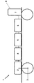
一つだけの図には、専ら電動機で駆動される自動車1をベースとする本解決策による駆動コンセプトが図解されており、この駆動コンセプトでは、ドライブシャフト3の駆動に用いられる駆動に必要な少なくとも一つの電動機2が、電気エネルギー貯蔵器4と結合しており、この電気エネルギー貯蔵器は、一価又は二価のガスエンジン6で駆動される発電機5によって充電される。ガスエンジン6を動作させるための燃料7は、自動車1により積載されている適切な燃料タンク8に蓄えられている。本解決策による動作方式は、電動機2の平均的な出力需要とガスエンジン6の平均的な出力放出量とを適応させることを基礎とする。こうすることで、自動車1の走行中に、積載されているエネルギー貯蔵ユニット4の充電状態が変化しないか又はさほど変化しないことを保証することができる。
Only one figure illustrates the drive concept according to the present solution, which is based exclusively on a
この動作方式により初めて、電気エネルギー貯蔵ユニット4を、すべてのこれまで知られている解決策の場合のように航続距離を決定するエネルギー源としては形成しないことが可能となり、むしろエネルギー貯蔵ユニット4は、ガスエンジン6及びガスエンジンの後ろに接続された発電機5によって生成された電気エネルギーのためのバッファーユニット又は中間貯蔵ユニットとしてのみ用いられる。理論上の極端な場合には、電気エネルギー貯蔵ユニット4をただのコンデンサーの形態で形成することもでき、このコンデンサーの充電容量はシステムに基づいて制限されており、コンデンサーに中間貯蔵された電気エネルギーを電動機2に転送するためだけに用いられる。エネルギー貯蔵ユニット4は、典型的にはニッケル水素、アルカリマンガンバッテリー、塩化亜鉛バッテリー、又は亜鉛炭素バッテリーの形態で形成されている。
For the first time, this mode of operation makes it possible not to form the electrical energy storage unit 4 as an energy source for determining the cruising range as in all previously known solutions, rather the energy storage unit 4 It is only used as a buffer unit or intermediate storage unit for the electric energy generated by the gas engine 6 and the
充電容量を最適化した非常に今風のバッテリーシステムとは違うエネルギー貯蔵ユニット4のまったく異なる機能方式により、充電容量特性に関し、質的に高価値の要求は存在せず、したがって本解決策による駆動コンセプトは、従来の、及びとりわけ安価なエネルギー貯蔵ユニットの使用を可能にする。本解決策による方法が少なくとも一つの最適化された作用点でのガスエンジン6の動作を可能にすることが加わると、従来の駆動技術にも関わらず、最も経済的でまたエコロジーな要求に対応する。電動機で駆動される自動車1の本解決策による駆動コンセプトによって到達可能な最大航続距離は、ガスエンジン6の着火のための積載されている燃料7、例えば液化石油ガス(LPG)又は圧縮天然ガス(CNG)によって有力に決定される。こうすることで、従来式に駆動される自動車1の航続距離に相当する航続距離が可能となり、したがって最終顧客にとっては、最新の構造形式の電気自動車でそうであるような航続距離の鬱積がない。
Due to the completely different functional scheme of the energy storage unit 4 which is different from the very modern battery system with optimized charge capacity, there is no qualitatively high value requirement for the charge capacity characteristics, so the driving concept according to this solution Enables the use of conventional and especially inexpensive energy storage units. When the method according to this solution is added to enable the operation of the gas engine 6 with at least one optimized working point, it meets the most economical and ecological demands despite the conventional drive technology To do. The maximum cruising range that can be reached by the driving concept of this solution for motor-driven
1 自動車
2 電動機
3 ドライブハブ
4 エネルギー貯蔵ユニット
5 発電機
6 ガスエンジン
7 燃料
8 燃料タンク
1 car
2 Electric motor
3 Drive hub
4 Energy storage unit
5 Generator
6 Gas engine
7 Fuel
8 Fuel tank
Claims (12)
前記自動車(1)が動いている間は、前記電動機(2)に割当可能な平均的な出力需要が前記ガスエンジン(6)に割当可能な平均的な出力放出量に相当するように前記ガスエンジン(6)を動作させ、したがって前記エネルギー貯蔵ユニット(4)に割当可能な充電状態が、変化しないか又は許容差を足した充電状態範囲内でしか変化しないことを特徴とする駆動方法。 At least one electric motor (2) is indirectly or directly coupled to the drive shaft (3) or drive hub of the automobile (1) in order to move the automobile (1) exclusively by the electric motor, and the electric motor (2) Is supplied with electrical energy via an energy storage unit (4), and the electrical energy storage unit (4) is supplied with a charging current by a generator (5) driven by a gas engine (6), In the driving method of the automobile (1),
While the automobile (1) is in motion, the gas output so that the average output demand that can be allocated to the electric motor (2) corresponds to the average output discharge amount that can be allocated to the gas engine (6). A driving method, characterized in that the engine (6) is operated and therefore the state of charge that can be allocated to the energy storage unit (4) does not change or changes only within a range of state of charge plus a tolerance.
前記一部分が、最大航続距離の少なくとも60%、好ましくは少なくとも70%、特に好ましくは少なくとも90%であることを特徴とする請求項1から5のいずれか一項に記載の方法。 The maximum charge capacity that can be allocated to the energy storage unit (4) and the maximum amount of fuel (7) loaded on the vehicle (1) are part of the maximum cruising distance reachable by the vehicle (1), Selected to be achieved only by combustion of the fuel (7) in the gas engine (6) and conversion to electrical energy for driving the vehicle (1) by the generator (5). And the portion is at least 60%, preferably at least 70%, particularly preferably at least 90% of the maximum cruising range.
前記ガスエンジン(6)が一価又は二価のガスエンジンであり、前記電気エネルギー貯蔵ユニット(4)の充電容量が、前記自動車(1)に対して航続距離を決定しないことを特徴とする駆動システム。 At least one motor (2), which is indirectly or directly coupled to the drive shaft (3) or drive hub of the vehicle (1), and electrically coupled to the motor (2) for electrical energy supply. An electric energy storage unit (4), and a generator (5) electrically coupled to the electric energy storage unit (4) for supplying charging current, and a gas operatively coupled to generate current In the drive system for the automobile (1) comprising an engine (6),
The gas engine (6) is a monovalent or divalent gas engine, and the charge capacity of the electric energy storage unit (4) does not determine a cruising distance with respect to the automobile (1) system.
前記一部分が、少なくとも60%、好ましくは少なくとも70%、特に好ましくは少なくとも90%であることを特徴とする請求項9に記載の駆動システム。 The maximum charging capacity of the energy storage unit (4) and the maximum amount of fuel (7) loaded by the automobile (1) are such that the maximum cruising distance reachable by the automobile (1) is a part of the cruising distance. Is selected to be achieved only by combustion of the fuel (7) in the gas engine (6) and conversion to electrical energy for driving the automobile (1) by the generator (5). 10. Drive system according to claim 9, characterized in that the portion is at least 60%, preferably at least 70%, particularly preferably at least 90%.
12.The gas engine (6) according to any one of claims 9 to 11, characterized in that it comprises a fuel tank (8) for liquefied petroleum gas (LPG) or compressed natural gas (CNG). Drive system.
Applications Claiming Priority (3)
| Application Number | Priority Date | Filing Date | Title |
|---|---|---|---|
| DE102013014457.4 | 2013-08-30 | ||
| DE102013014457.4A DE102013014457A1 (en) | 2013-08-30 | 2013-08-30 | Method for driving a motor vehicle and drive system for a motor vehicle |
| PCT/EP2014/002329 WO2015028147A1 (en) | 2013-08-30 | 2014-08-26 | Method for driving a motor vehicle and drive system for a motor vehicle |
Publications (1)
| Publication Number | Publication Date |
|---|---|
| JP2016533957A true JP2016533957A (en) | 2016-11-04 |
Family
ID=51422044
Family Applications (1)
| Application Number | Title | Priority Date | Filing Date |
|---|---|---|---|
| JP2016537162A Pending JP2016533957A (en) | 2013-08-30 | 2014-08-26 | Driving method for automobile and driving system for automobile |
Country Status (8)
| Country | Link |
|---|---|
| US (1) | US20160207404A1 (en) |
| EP (1) | EP3038848B1 (en) |
| JP (1) | JP2016533957A (en) |
| KR (1) | KR20160048094A (en) |
| CN (1) | CN105473364B (en) |
| BR (1) | BR112016004312B1 (en) |
| DE (1) | DE102013014457A1 (en) |
| WO (1) | WO2015028147A1 (en) |
Families Citing this family (7)
| Publication number | Priority date | Publication date | Assignee | Title |
|---|---|---|---|---|
| US10337424B2 (en) * | 2014-12-02 | 2019-07-02 | Electronic Power Design, Inc. | System and method for energy management using linear programming |
| US10530290B2 (en) * | 2014-12-02 | 2020-01-07 | Electronic Power Design, Inc. | System and method for hybrid power generation |
| SE542110C2 (en) * | 2016-06-21 | 2020-02-25 | Scania Cv Ab | A method and a system for controlling a gas engine |
| US11333085B2 (en) * | 2017-01-25 | 2022-05-17 | Electronic Power Design, Inc. | System and method for energy management using linear programming |
| DE102018103246A1 (en) * | 2018-02-14 | 2019-08-14 | HELLA GmbH & Co. KGaA | Motor vehicle drive system and motor vehicle |
| CN110203090A (en) * | 2019-05-07 | 2019-09-06 | 北京九曜智能科技有限公司 | Movable charging vehicle and its charging method |
| DE102021105089B3 (en) | 2021-03-03 | 2022-02-10 | CM Fluids AG | Caloric vehicle management system |
Citations (5)
| Publication number | Priority date | Publication date | Assignee | Title |
|---|---|---|---|---|
| JPH03270603A (en) * | 1990-03-20 | 1991-12-02 | Nkk Corp | Electric car |
| JPH0998515A (en) * | 1995-07-25 | 1997-04-08 | Nippon Soken Inc | Engine controller for hybrid vehicle |
| JP2002199509A (en) * | 2000-12-25 | 2002-07-12 | Fuji Electric Co Ltd | Driving method of hybrid vehicle |
| JP2012056559A (en) * | 2010-08-13 | 2012-03-22 | Honda Motor Co Ltd | Hybrid vehicle control device |
| JP2013513522A (en) * | 2009-12-17 | 2013-04-22 | ローベルト ボツシユ ゲゼルシヤフト ミツト ベシユレンクテル ハフツング | Range extender for automobile |
Family Cites Families (54)
| Publication number | Priority date | Publication date | Assignee | Title |
|---|---|---|---|---|
| DE3732869A1 (en) | 1987-09-30 | 1989-04-20 | Adolf Dipl Ing Kindler | Power unit on trailers for electric cars |
| US5172784A (en) * | 1991-04-19 | 1992-12-22 | Varela Jr Arthur A | Hybrid electric propulsion system |
| DE4121386A1 (en) | 1991-06-28 | 1993-01-07 | Bayerische Motoren Werke Ag | Hybrid vehicle comprising electric motor car with removable power trailer - carrying IC engine operating generator for direct propulsion, via buffered battery of towing vehicle's electric motors |
| FR2705928B1 (en) * | 1993-06-02 | 1995-07-21 | Smh Management Services Ag | Motor vehicle with electric traction. |
| DE9404746U1 (en) | 1994-03-21 | 1994-06-01 | Schlueter Martina | Energy supply trailer for electric automobiles (power trailers) |
| DE19509625A1 (en) | 1995-03-21 | 1995-11-02 | Schlueter Martina | Power-supply trailer for urban electric car |
| US6116363A (en) * | 1995-05-31 | 2000-09-12 | Frank Transportation Technology, Llc | Fuel consumption control for charge depletion hybrid electric vehicles |
| WO1998028832A1 (en) * | 1996-12-20 | 1998-07-02 | Manuel Dos Santos Da Ponte | Hybrid generator apparatus |
| US6554088B2 (en) * | 1998-09-14 | 2003-04-29 | Paice Corporation | Hybrid vehicles |
| JP3385986B2 (en) * | 1998-12-18 | 2003-03-10 | 本田技研工業株式会社 | Output control device for series hybrid vehicles |
| US7252165B1 (en) * | 2000-04-26 | 2007-08-07 | Bowling Green State University | Hybrid electric vehicle |
| US7391129B2 (en) * | 2002-05-31 | 2008-06-24 | Ise Corporation | System and method for powering accessories in a hybrid vehicle |
| JP4248303B2 (en) * | 2003-05-09 | 2009-04-02 | 本田技研工業株式会社 | Power unit comprising a combustion engine and a Stirling engine |
| FR2854847B1 (en) * | 2003-05-16 | 2007-03-23 | Peugeot Citroen Automobiles Sa | MOTORPOWER GROUP OF A MOTOR VEHICLE |
| CN1298560C (en) * | 2003-12-30 | 2007-02-07 | 联合汽车电子有限公司 | Mixed power automobile control system and its control method |
| DE102004035341B4 (en) * | 2004-07-21 | 2012-05-16 | Volkswagen Ag | hybrid vehicle |
| DE102005035313A1 (en) | 2005-07-28 | 2007-02-01 | Hager, Ronald | Drive system for cars, trucks, trains and buses comprises an electric motor arranged on each wheel of the vehicle, electronic devices for controlling the motors and electrolyte capacitors as energy storage units |
| JP4390785B2 (en) * | 2006-05-24 | 2009-12-24 | トヨタ自動車株式会社 | Driving force control device for four-wheel drive vehicle |
| US7292932B1 (en) * | 2006-11-13 | 2007-11-06 | Ford Global Technologies, Llc | System and method for controlling speed of an engine |
| DE102007004172A1 (en) * | 2007-01-27 | 2008-07-31 | Volkswagen Ag | Motor vehicle e.g. zero emission vehicle, has generator activated and/or deactivated in parking condition of vehicle and started after activation of drive, where disconnection of drive of generator is carried out after deactivation |
| US7726130B2 (en) * | 2007-05-11 | 2010-06-01 | Joseph Shea McDowell | Stirling-electric hybrid automobile |
| US8022674B2 (en) * | 2007-07-10 | 2011-09-20 | Toyota Motor Engineering & Manufacturing North America, Inc. | State of charge control method and systems for vehicles |
| GB0720151D0 (en) | 2007-10-15 | 2007-11-28 | Delaney Christopher B | A hybrid powertrain |
| US8138720B2 (en) * | 2008-02-26 | 2012-03-20 | Afs Trinity Power Corporation | System and method for dual energy storage management |
| US8225900B2 (en) * | 2008-04-26 | 2012-07-24 | Domes Timothy J | Pneumatic mechanical power source |
| US20090288899A1 (en) * | 2008-05-20 | 2009-11-26 | Belloso Gregorio M | Vehicle with multiple engines coupled to a transmission via a jackshaft |
| US8561744B1 (en) * | 2008-05-20 | 2013-10-22 | Gregorio M. Belloso | Vehicle with multiple engines coupled to a transmission via a jackshaft |
| US7911180B2 (en) | 2008-07-31 | 2011-03-22 | GM Global Technology Operations LLC | Single-phase phase locked loop suitable for use in a hybrid vehicle charging system and method for charging a hybrid vehicle from a single-phase power source |
| US8337359B2 (en) * | 2008-08-27 | 2012-12-25 | EcoMotors International | Hybrid engine system |
| US8290653B2 (en) * | 2008-08-27 | 2012-10-16 | Ecomotors International, Inc. | Powertrain with multiple, selectable power sources |
| DE102008051324A1 (en) | 2008-10-11 | 2010-04-15 | Desider Boda | Drive for e.g. commercial vehicle, has electric motor provided in position to drive auxiliary load in mechanically connected manner, where electric motor drives hybrid vehicle when internal combustion engine is switched off |
| DE102009000530A1 (en) | 2009-02-02 | 2010-08-05 | Robert Bosch Gmbh | Hybrid drive device i.e. serial hybrid drive device, for motor vehicle, has two drive assemblies, where one of drive assemblies comprises electric motor and other drive assembly comprises gas turbine |
| DE102009045979A1 (en) | 2009-10-26 | 2011-04-28 | Robert Bosch Gmbh | Drive device for electric vehicle, has expansion machine formed as gas turbine that has combustion chamber for mixture of fresh air and solid, liquid and/or gaseous fuel, where combustion chamber is connected upstream of turbine |
| US8855840B2 (en) * | 2010-02-03 | 2014-10-07 | Toyota Motor Engineering & Manufacturing North America, Inc. | Method and system for more efficient operation of plug-in electric vehicles |
| DE102010009832A1 (en) * | 2010-03-02 | 2011-09-08 | Ivd Prof. Hohenberg Gmbh | Motor vehicle with combined drive |
| DE102010028312A1 (en) | 2010-04-28 | 2011-11-03 | Ford Global Technologies, Llc | Electrically propelled vehicle i.e. electric car, for long haul travel, has separate power supply unit for supplying supplementary electrical power, where separate power supply unit is attached on fixed and removable trailer couplings |
| WO2012138991A2 (en) * | 2011-04-08 | 2012-10-11 | Polaris Industries Inc. | Electric vehicle with range extender |
| DE102011102423A1 (en) * | 2011-05-24 | 2012-11-29 | Audi Ag | Method for operating a motor vehicle |
| DE102011105618A1 (en) * | 2011-06-28 | 2013-01-03 | Audi Ag | Method of controlling a range extension device and range extension device |
| US8606450B2 (en) * | 2011-09-09 | 2013-12-10 | GM Global Technology Operations LLC | Hybrid powertrain with geared starter motor and belt alternator starter and method of restarting an engine |
| US8761981B2 (en) * | 2011-10-18 | 2014-06-24 | Fuel Motion Inc. | Method and apparatus for a vehicle control unit (VCU), using current and historical instantaneous power usage data, to determine optimum power settings for a hybrid electric drive system |
| US9365210B2 (en) * | 2011-11-08 | 2016-06-14 | Volvo Lastvagnar Ab | Method and arrangement in a hybrid vehicle |
| US8907629B2 (en) * | 2012-02-28 | 2014-12-09 | Tesla Motors, Inc. | Electric vehicle battery lifetime optimization operational mode |
| US9321358B2 (en) * | 2012-07-06 | 2016-04-26 | Xtreme Products, Inc. | Light vehicles with on-board rapid charging systems and associated methods |
| US9705353B2 (en) * | 2012-07-11 | 2017-07-11 | Ford Global Technologies, Llc | Method and system for heating traction battery of electric vehicle |
| WO2014018503A1 (en) * | 2012-07-25 | 2014-01-30 | Fisker Automotive, Inc. | All wheel drive system for hybrid vehicle |
| US9296309B2 (en) * | 2012-09-12 | 2016-03-29 | Ford Global Technologies, Llc | Customized battery charging |
| CN104125904B (en) * | 2012-09-24 | 2017-08-08 | 株式会社久保田 | Vehicle |
| US20140114514A1 (en) * | 2012-10-19 | 2014-04-24 | Ford Global Technologies, Llc | Delayed electric-only operation of a hybrid vehicle |
| KR101836527B1 (en) * | 2012-12-05 | 2018-03-08 | 현대자동차주식회사 | System and method for learning transfering torque for hybrid vehicle |
| KR101775547B1 (en) * | 2013-01-16 | 2017-09-06 | 삼성에스디아이 주식회사 | Battery system comprising different kinds of cells and power device comprising the same |
| US9162666B2 (en) * | 2013-03-15 | 2015-10-20 | GM Global Technology Operations LLC | Hybrid vehicle and method of braking by controlling an exhaust heat recovery device bypass valve on a hybrid vehicle |
| EP3206294B1 (en) * | 2014-11-25 | 2019-10-30 | Yamaha Hatsudoki Kabushiki Kaisha | Vehicle |
| US9815373B2 (en) * | 2015-02-23 | 2017-11-14 | Ford Global Technologies, Llc | Battery state of charge target based on predicted regenerative energy |
-
2013
- 2013-08-30 DE DE102013014457.4A patent/DE102013014457A1/en not_active Withdrawn
-
2014
- 2014-08-26 WO PCT/EP2014/002329 patent/WO2015028147A1/en active Application Filing
- 2014-08-26 KR KR1020167005520A patent/KR20160048094A/en not_active IP Right Cessation
- 2014-08-26 CN CN201480046833.XA patent/CN105473364B/en active Active
- 2014-08-26 JP JP2016537162A patent/JP2016533957A/en active Pending
- 2014-08-26 EP EP14755988.4A patent/EP3038848B1/en active Active
- 2014-08-26 US US14/915,436 patent/US20160207404A1/en not_active Abandoned
- 2014-08-26 BR BR112016004312-0A patent/BR112016004312B1/en active IP Right Grant
Patent Citations (5)
| Publication number | Priority date | Publication date | Assignee | Title |
|---|---|---|---|---|
| JPH03270603A (en) * | 1990-03-20 | 1991-12-02 | Nkk Corp | Electric car |
| JPH0998515A (en) * | 1995-07-25 | 1997-04-08 | Nippon Soken Inc | Engine controller for hybrid vehicle |
| JP2002199509A (en) * | 2000-12-25 | 2002-07-12 | Fuji Electric Co Ltd | Driving method of hybrid vehicle |
| JP2013513522A (en) * | 2009-12-17 | 2013-04-22 | ローベルト ボツシユ ゲゼルシヤフト ミツト ベシユレンクテル ハフツング | Range extender for automobile |
| JP2012056559A (en) * | 2010-08-13 | 2012-03-22 | Honda Motor Co Ltd | Hybrid vehicle control device |
Also Published As
| Publication number | Publication date |
|---|---|
| EP3038848A1 (en) | 2016-07-06 |
| CN105473364A (en) | 2016-04-06 |
| DE102013014457A1 (en) | 2015-03-05 |
| EP3038848B1 (en) | 2017-10-18 |
| BR112016004312B1 (en) | 2022-05-10 |
| US20160207404A1 (en) | 2016-07-21 |
| BR112016004312A2 (en) | 2017-08-01 |
| WO2015028147A1 (en) | 2015-03-05 |
| CN105473364B (en) | 2017-12-19 |
| KR20160048094A (en) | 2016-05-03 |
Similar Documents
| Publication | Publication Date | Title |
|---|---|---|
| JP2016533957A (en) | Driving method for automobile and driving system for automobile | |
| Vidyanandan | Overview of electric and hybrid vehicles | |
| US9457671B2 (en) | Drive system for a motor vehicle | |
| EP3424770B1 (en) | Extended-range electric passenger vehicle having front-mounted engine | |
| US8657046B2 (en) | Engine system | |
| US9956873B1 (en) | Electric vehicles with extended range | |
| US8517129B2 (en) | Motorized dual engine power system | |
| US8875819B2 (en) | Hybrid drive system for hybrid electric vehicles | |
| CN202896272U (en) | Novel series-parallel hybrid electric vehicle | |
| US20140116793A1 (en) | Hybrid vehicle | |
| CN104837702A (en) | Hybrid electric vehicle control system and method | |
| JP5301658B2 (en) | Hybrid vehicle | |
| WO2013070407A1 (en) | Power hybrid integrated management system | |
| WO2010133330A1 (en) | Multi component propulsion systems for road vehicles | |
| KR20200115646A (en) | Hybrid powertrain | |
| US20130133180A1 (en) | Electric vehicle motion generator | |
| US11097717B2 (en) | Electric vehicles with extended range | |
| EP2463169A1 (en) | A hybride vehicle | |
| EP0218632A1 (en) | Battery-powered vehicle | |
| Yadav et al. | Innovative Method for Enhancing E-Bikes Performance through riding mechanical force | |
| Kaźmierczak et al. | Project of hybrid motor system in scooter | |
| Ignatyugin et al. | ELECTRIC CARS | |
| Duysinx | MECA0527: HYBRID ELECTRIC VEHICLES | |
| CA2719462A1 (en) | Electric vehicle motion generator |
Legal Events
| Date | Code | Title | Description |
|---|---|---|---|
| A529 | Written submission of copy of amendment under article 34 pct |
Free format text: JAPANESE INTERMEDIATE CODE: A529 Effective date: 20160418 |
|
| RD01 | Notification of change of attorney |
Free format text: JAPANESE INTERMEDIATE CODE: A7426 Effective date: 20160812 |
|
| A521 | Request for written amendment filed |
Free format text: JAPANESE INTERMEDIATE CODE: A821 Effective date: 20160812 |
|
| A621 | Written request for application examination |
Free format text: JAPANESE INTERMEDIATE CODE: A621 Effective date: 20170310 |
|
| A977 | Report on retrieval |
Free format text: JAPANESE INTERMEDIATE CODE: A971007 Effective date: 20171213 |
|
| A131 | Notification of reasons for refusal |
Free format text: JAPANESE INTERMEDIATE CODE: A131 Effective date: 20180109 |
|
| A521 | Request for written amendment filed |
Free format text: JAPANESE INTERMEDIATE CODE: A523 Effective date: 20180409 |
|
| A131 | Notification of reasons for refusal |
Free format text: JAPANESE INTERMEDIATE CODE: A131 Effective date: 20181002 |
|
| A601 | Written request for extension of time |
Free format text: JAPANESE INTERMEDIATE CODE: A601 Effective date: 20181221 |
|
| A521 | Request for written amendment filed |
Free format text: JAPANESE INTERMEDIATE CODE: A523 Effective date: 20190315 |
|
| A02 | Decision of refusal |
Free format text: JAPANESE INTERMEDIATE CODE: A02 Effective date: 20190730 |