JP2016524889A - Magnetic field sensing device for wireless power transfer system - Google Patents
Magnetic field sensing device for wireless power transfer system Download PDFInfo
- Publication number
- JP2016524889A JP2016524889A JP2016513969A JP2016513969A JP2016524889A JP 2016524889 A JP2016524889 A JP 2016524889A JP 2016513969 A JP2016513969 A JP 2016513969A JP 2016513969 A JP2016513969 A JP 2016513969A JP 2016524889 A JP2016524889 A JP 2016524889A
- Authority
- JP
- Japan
- Prior art keywords
- wireless power
- controller
- power receiver
- power
- receiver
- Prior art date
- Legal status (The legal status is an assumption and is not a legal conclusion. Google has not performed a legal analysis and makes no representation as to the accuracy of the status listed.)
- Pending
Links
Images

Classifications
-
- B—PERFORMING OPERATIONS; TRANSPORTING
- B60—VEHICLES IN GENERAL
- B60L—PROPULSION OF ELECTRICALLY-PROPELLED VEHICLES; SUPPLYING ELECTRIC POWER FOR AUXILIARY EQUIPMENT OF ELECTRICALLY-PROPELLED VEHICLES; ELECTRODYNAMIC BRAKE SYSTEMS FOR VEHICLES IN GENERAL; MAGNETIC SUSPENSION OR LEVITATION FOR VEHICLES; MONITORING OPERATING VARIABLES OF ELECTRICALLY-PROPELLED VEHICLES; ELECTRIC SAFETY DEVICES FOR ELECTRICALLY-PROPELLED VEHICLES
- B60L53/00—Methods of charging batteries, specially adapted for electric vehicles; Charging stations or on-board charging equipment therefor; Exchange of energy storage elements in electric vehicles
- B60L53/30—Constructional details of charging stations
-
- B—PERFORMING OPERATIONS; TRANSPORTING
- B60—VEHICLES IN GENERAL
- B60L—PROPULSION OF ELECTRICALLY-PROPELLED VEHICLES; SUPPLYING ELECTRIC POWER FOR AUXILIARY EQUIPMENT OF ELECTRICALLY-PROPELLED VEHICLES; ELECTRODYNAMIC BRAKE SYSTEMS FOR VEHICLES IN GENERAL; MAGNETIC SUSPENSION OR LEVITATION FOR VEHICLES; MONITORING OPERATING VARIABLES OF ELECTRICALLY-PROPELLED VEHICLES; ELECTRIC SAFETY DEVICES FOR ELECTRICALLY-PROPELLED VEHICLES
- B60L53/00—Methods of charging batteries, specially adapted for electric vehicles; Charging stations or on-board charging equipment therefor; Exchange of energy storage elements in electric vehicles
- B60L53/10—Methods of charging batteries, specially adapted for electric vehicles; Charging stations or on-board charging equipment therefor; Exchange of energy storage elements in electric vehicles characterised by the energy transfer between the charging station and the vehicle
- B60L53/12—Inductive energy transfer
- B60L53/122—Circuits or methods for driving the primary coil, e.g. supplying electric power to the coil
-
- B—PERFORMING OPERATIONS; TRANSPORTING
- B60—VEHICLES IN GENERAL
- B60L—PROPULSION OF ELECTRICALLY-PROPELLED VEHICLES; SUPPLYING ELECTRIC POWER FOR AUXILIARY EQUIPMENT OF ELECTRICALLY-PROPELLED VEHICLES; ELECTRODYNAMIC BRAKE SYSTEMS FOR VEHICLES IN GENERAL; MAGNETIC SUSPENSION OR LEVITATION FOR VEHICLES; MONITORING OPERATING VARIABLES OF ELECTRICALLY-PROPELLED VEHICLES; ELECTRIC SAFETY DEVICES FOR ELECTRICALLY-PROPELLED VEHICLES
- B60L53/00—Methods of charging batteries, specially adapted for electric vehicles; Charging stations or on-board charging equipment therefor; Exchange of energy storage elements in electric vehicles
- B60L53/30—Constructional details of charging stations
- B60L53/305—Communication interfaces
-
- B—PERFORMING OPERATIONS; TRANSPORTING
- B60—VEHICLES IN GENERAL
- B60L—PROPULSION OF ELECTRICALLY-PROPELLED VEHICLES; SUPPLYING ELECTRIC POWER FOR AUXILIARY EQUIPMENT OF ELECTRICALLY-PROPELLED VEHICLES; ELECTRODYNAMIC BRAKE SYSTEMS FOR VEHICLES IN GENERAL; MAGNETIC SUSPENSION OR LEVITATION FOR VEHICLES; MONITORING OPERATING VARIABLES OF ELECTRICALLY-PROPELLED VEHICLES; ELECTRIC SAFETY DEVICES FOR ELECTRICALLY-PROPELLED VEHICLES
- B60L58/00—Methods or circuit arrangements for monitoring or controlling batteries or fuel cells, specially adapted for electric vehicles
- B60L58/10—Methods or circuit arrangements for monitoring or controlling batteries or fuel cells, specially adapted for electric vehicles for monitoring or controlling batteries
- B60L58/18—Methods or circuit arrangements for monitoring or controlling batteries or fuel cells, specially adapted for electric vehicles for monitoring or controlling batteries of two or more battery modules
- B60L58/21—Methods or circuit arrangements for monitoring or controlling batteries or fuel cells, specially adapted for electric vehicles for monitoring or controlling batteries of two or more battery modules having the same nominal voltage
-
- H—ELECTRICITY
- H02—GENERATION; CONVERSION OR DISTRIBUTION OF ELECTRIC POWER
- H02J—CIRCUIT ARRANGEMENTS OR SYSTEMS FOR SUPPLYING OR DISTRIBUTING ELECTRIC POWER; SYSTEMS FOR STORING ELECTRIC ENERGY
- H02J50/00—Circuit arrangements or systems for wireless supply or distribution of electric power
- H02J50/10—Circuit arrangements or systems for wireless supply or distribution of electric power using inductive coupling
- H02J50/12—Circuit arrangements or systems for wireless supply or distribution of electric power using inductive coupling of the resonant type
-
- H—ELECTRICITY
- H02—GENERATION; CONVERSION OR DISTRIBUTION OF ELECTRIC POWER
- H02J—CIRCUIT ARRANGEMENTS OR SYSTEMS FOR SUPPLYING OR DISTRIBUTING ELECTRIC POWER; SYSTEMS FOR STORING ELECTRIC ENERGY
- H02J50/00—Circuit arrangements or systems for wireless supply or distribution of electric power
- H02J50/80—Circuit arrangements or systems for wireless supply or distribution of electric power involving the exchange of data, concerning supply or distribution of electric power, between transmitting devices and receiving devices
-
- H—ELECTRICITY
- H02—GENERATION; CONVERSION OR DISTRIBUTION OF ELECTRIC POWER
- H02J—CIRCUIT ARRANGEMENTS OR SYSTEMS FOR SUPPLYING OR DISTRIBUTING ELECTRIC POWER; SYSTEMS FOR STORING ELECTRIC ENERGY
- H02J7/00—Circuit arrangements for charging or depolarising batteries or for supplying loads from batteries
- H02J7/00032—Circuit arrangements for charging or depolarising batteries or for supplying loads from batteries characterised by data exchange
- H02J7/00034—Charger exchanging data with an electronic device, i.e. telephone, whose internal battery is under charge
-
- B—PERFORMING OPERATIONS; TRANSPORTING
- B60—VEHICLES IN GENERAL
- B60L—PROPULSION OF ELECTRICALLY-PROPELLED VEHICLES; SUPPLYING ELECTRIC POWER FOR AUXILIARY EQUIPMENT OF ELECTRICALLY-PROPELLED VEHICLES; ELECTRODYNAMIC BRAKE SYSTEMS FOR VEHICLES IN GENERAL; MAGNETIC SUSPENSION OR LEVITATION FOR VEHICLES; MONITORING OPERATING VARIABLES OF ELECTRICALLY-PROPELLED VEHICLES; ELECTRIC SAFETY DEVICES FOR ELECTRICALLY-PROPELLED VEHICLES
- B60L2210/00—Converter types
- B60L2210/30—AC to DC converters
-
- H—ELECTRICITY
- H02—GENERATION; CONVERSION OR DISTRIBUTION OF ELECTRIC POWER
- H02J—CIRCUIT ARRANGEMENTS OR SYSTEMS FOR SUPPLYING OR DISTRIBUTING ELECTRIC POWER; SYSTEMS FOR STORING ELECTRIC ENERGY
- H02J2310/00—The network for supplying or distributing electric power characterised by its spatial reach or by the load
- H02J2310/40—The network being an on-board power network, i.e. within a vehicle
- H02J2310/48—The network being an on-board power network, i.e. within a vehicle for electric vehicles [EV] or hybrid vehicles [HEV]
-
- Y—GENERAL TAGGING OF NEW TECHNOLOGICAL DEVELOPMENTS; GENERAL TAGGING OF CROSS-SECTIONAL TECHNOLOGIES SPANNING OVER SEVERAL SECTIONS OF THE IPC; TECHNICAL SUBJECTS COVERED BY FORMER USPC CROSS-REFERENCE ART COLLECTIONS [XRACs] AND DIGESTS
- Y02—TECHNOLOGIES OR APPLICATIONS FOR MITIGATION OR ADAPTATION AGAINST CLIMATE CHANGE
- Y02T—CLIMATE CHANGE MITIGATION TECHNOLOGIES RELATED TO TRANSPORTATION
- Y02T10/00—Road transport of goods or passengers
- Y02T10/60—Other road transportation technologies with climate change mitigation effect
- Y02T10/70—Energy storage systems for electromobility, e.g. batteries
-
- Y—GENERAL TAGGING OF NEW TECHNOLOGICAL DEVELOPMENTS; GENERAL TAGGING OF CROSS-SECTIONAL TECHNOLOGIES SPANNING OVER SEVERAL SECTIONS OF THE IPC; TECHNICAL SUBJECTS COVERED BY FORMER USPC CROSS-REFERENCE ART COLLECTIONS [XRACs] AND DIGESTS
- Y02—TECHNOLOGIES OR APPLICATIONS FOR MITIGATION OR ADAPTATION AGAINST CLIMATE CHANGE
- Y02T—CLIMATE CHANGE MITIGATION TECHNOLOGIES RELATED TO TRANSPORTATION
- Y02T10/00—Road transport of goods or passengers
- Y02T10/60—Other road transportation technologies with climate change mitigation effect
- Y02T10/7072—Electromobility specific charging systems or methods for batteries, ultracapacitors, supercapacitors or double-layer capacitors
-
- Y—GENERAL TAGGING OF NEW TECHNOLOGICAL DEVELOPMENTS; GENERAL TAGGING OF CROSS-SECTIONAL TECHNOLOGIES SPANNING OVER SEVERAL SECTIONS OF THE IPC; TECHNICAL SUBJECTS COVERED BY FORMER USPC CROSS-REFERENCE ART COLLECTIONS [XRACs] AND DIGESTS
- Y02—TECHNOLOGIES OR APPLICATIONS FOR MITIGATION OR ADAPTATION AGAINST CLIMATE CHANGE
- Y02T—CLIMATE CHANGE MITIGATION TECHNOLOGIES RELATED TO TRANSPORTATION
- Y02T10/00—Road transport of goods or passengers
- Y02T10/60—Other road transportation technologies with climate change mitigation effect
- Y02T10/72—Electric energy management in electromobility
-
- Y—GENERAL TAGGING OF NEW TECHNOLOGICAL DEVELOPMENTS; GENERAL TAGGING OF CROSS-SECTIONAL TECHNOLOGIES SPANNING OVER SEVERAL SECTIONS OF THE IPC; TECHNICAL SUBJECTS COVERED BY FORMER USPC CROSS-REFERENCE ART COLLECTIONS [XRACs] AND DIGESTS
- Y02—TECHNOLOGIES OR APPLICATIONS FOR MITIGATION OR ADAPTATION AGAINST CLIMATE CHANGE
- Y02T—CLIMATE CHANGE MITIGATION TECHNOLOGIES RELATED TO TRANSPORTATION
- Y02T90/00—Enabling technologies or technologies with a potential or indirect contribution to GHG emissions mitigation
- Y02T90/10—Technologies relating to charging of electric vehicles
- Y02T90/12—Electric charging stations
-
- Y—GENERAL TAGGING OF NEW TECHNOLOGICAL DEVELOPMENTS; GENERAL TAGGING OF CROSS-SECTIONAL TECHNOLOGIES SPANNING OVER SEVERAL SECTIONS OF THE IPC; TECHNICAL SUBJECTS COVERED BY FORMER USPC CROSS-REFERENCE ART COLLECTIONS [XRACs] AND DIGESTS
- Y02—TECHNOLOGIES OR APPLICATIONS FOR MITIGATION OR ADAPTATION AGAINST CLIMATE CHANGE
- Y02T—CLIMATE CHANGE MITIGATION TECHNOLOGIES RELATED TO TRANSPORTATION
- Y02T90/00—Enabling technologies or technologies with a potential or indirect contribution to GHG emissions mitigation
- Y02T90/10—Technologies relating to charging of electric vehicles
- Y02T90/14—Plug-in electric vehicles
-
- Y—GENERAL TAGGING OF NEW TECHNOLOGICAL DEVELOPMENTS; GENERAL TAGGING OF CROSS-SECTIONAL TECHNOLOGIES SPANNING OVER SEVERAL SECTIONS OF THE IPC; TECHNICAL SUBJECTS COVERED BY FORMER USPC CROSS-REFERENCE ART COLLECTIONS [XRACs] AND DIGESTS
- Y02—TECHNOLOGIES OR APPLICATIONS FOR MITIGATION OR ADAPTATION AGAINST CLIMATE CHANGE
- Y02T—CLIMATE CHANGE MITIGATION TECHNOLOGIES RELATED TO TRANSPORTATION
- Y02T90/00—Enabling technologies or technologies with a potential or indirect contribution to GHG emissions mitigation
- Y02T90/10—Technologies relating to charging of electric vehicles
- Y02T90/16—Information or communication technologies improving the operation of electric vehicles
Abstract
無線電力伝送システム(10)の捕捉共振器(38)とバッテリパックまたは電動機などの電気負荷(18)との間の電気的接続を制御するように構成された無線電力受信機(16)。無線電力受信機(16)の回路は捕捉共振器(38)からの電力出力によって直接的に電力を供給され、捕捉共振器(38)が電力の生成を開始し次第、無線電力受信機(16)を自動的に起動する。無線電力受信機(16)は、車両バッテリ(18)などの外部電源から供給される待機電力を必要としない。無線電力受信機(16)は外部電源からの電力を必要としないので、車両バッテリ(18)の充電状態が制御器(50)を作動するには低すぎるとしても、車両バッテリ(18)の充電を開始できる。【選択図】図1A wireless power receiver (16) configured to control an electrical connection between a capture resonator (38) of the wireless power transfer system (10) and an electrical load (18) such as a battery pack or motor. The circuitry of the wireless power receiver (16) is powered directly by the power output from the capture resonator (38), and as soon as the capture resonator (38) starts generating power, the wireless power receiver (16). ) Automatically. The wireless power receiver (16) does not require standby power supplied from an external power source such as a vehicle battery (18). Since the wireless power receiver (16) does not require power from an external power source, the vehicle battery (18) can be charged even if the state of charge of the vehicle battery (18) is too low to operate the controller (50). Can start. [Selection] Figure 1
Description
[0001]本発明は、概して、無線電力伝送システムに関し、より詳細には、磁場を検知し、無線電力受信機を起動させる装置に関する。 [0001] The present invention relates generally to wireless power transfer systems, and more particularly to an apparatus for sensing a magnetic field and activating a wireless power receiver.
[0002]無線電力伝送システムの供給源共振器と捕捉共振器との間の電力伝送は、通常、車両外の送信機制御器と車両上の受信機制御器との間で無線通信リンクが確立された後に開始される。電源と負荷との間の電力伝送は、負荷が使用可能なエネルギーを超えないように電源がエネルギーを供給するように制御されなければならない。受信機制御器は送信機制御器と通信し、負荷によって受け入れ可能なエネルギー伝送量を取り決める。 [0002] Power transfer between a source resonator and a capture resonator of a wireless power transfer system typically establishes a wireless communication link between a transmitter controller outside the vehicle and a receiver controller on the vehicle Will be started after. Power transfer between the power source and the load must be controlled so that the power source supplies energy so that the load does not exceed the available energy. The receiver controller communicates with the transmitter controller to negotiate the amount of energy transfer that can be accepted by the load.
[0003]例えば、オフピーク電力料金を利用するためなど、車両が供給源共振器の近くに停車後しばらくしてから電力伝送を開始するのが望ましい。このためには、受信機制御器は送信機制御器との通信を確立できなくてはならない。したがって、受信機制御器は、送信機制御器に応答可能な電源の入った状態または低電力の待機状態に維持されなくてはならない。どちらの例においても、受信機制御器は車両バッテリから電力を供給される必要がある。 [0003] It is desirable to start power transmission some time after the vehicle stops near the source resonator, eg, to take advantage of off-peak power charges. To do this, the receiver controller must be able to establish communication with the transmitter controller. Accordingly, the receiver controller must be maintained in a powered on or low power standby state capable of responding to the transmitter controller. In either example, the receiver controller needs to be powered from the vehicle battery.
[0004]背景技術セクションで説明される主題は、背景技術セクションにおいて言及していることのみをもって従来技術と見なされるべきではない。同様に、背景技術セクションにおいて言及された問題点または背景技術セクションの主題と関連する問題点は、従来技術において既に認識されていたと見なされるべきではない。背景技術における主題は、それ自体もまた発明であり得る異なる試みを単に提示するものである。 [0004] The subject matter described in the background art section should not be regarded as prior art only by reference in the background art section. Similarly, problems referred to in the background art section or related to the subject matter of the background art section should not be considered as already recognized in the prior art. The subject matter in the background art merely presents different attempts that may themselves be inventions.
[0005]本発明の一実施形態によると、無線電力送信機によって生成された交流磁場を受けるように構成された無線電力受信機が提供される。無線電力受信機は、交流磁場によって励起されたときに交流電流を生成するように構成された捕捉共振器を含む。無線電力受信機はまた、捕捉共振器に電気的に結合され、捕捉共振器によって生成された交流電流に励起されたときに直流電流を生成するように構成された電流変換回路も含む。無線電力受信機は、捕捉共振器と電気負荷との間の電気的接続を制御するように構成された装置を更に含む。 [0005] According to one embodiment of the present invention, a wireless power receiver configured to receive an alternating magnetic field generated by a wireless power transmitter is provided. The wireless power receiver includes a capture resonator configured to generate an alternating current when excited by an alternating magnetic field. The wireless power receiver also includes a current conversion circuit that is electrically coupled to the capture resonator and configured to generate a direct current when excited by an alternating current generated by the capture resonator. The wireless power receiver further includes a device configured to control the electrical connection between the capture resonator and the electrical load.
[0006]無線電力受信機はまた、制御器と通信しているとともに、前記無線電力送信機の第2の送受信機と通信するように構成された第1の送受信機も含み得る。装置はまた、前記制御器と通信しているとともに、実行されたときに装置に無線電力受信機と無線電力送信機との間に第1の送受信機を介して第1の通信リンクを確立させる命令を含むメモリ装置も含み得る。 [0006] The wireless power receiver may also include a first transceiver configured to communicate with a controller and to communicate with a second transceiver of the wireless power transmitter. The device is also in communication with the controller and when executed causes the device to establish a first communication link between the wireless power receiver and the wireless power transmitter via the first transceiver. A memory device containing instructions may also be included.
[0007]本発明の更なる特徴および利点は、添付の図面を参照して、単なる非限定的な例示として与えられる本発明の好ましい実施形態に関する以下の詳細な説明を読むことによってより明確になるであろう。 [0007] Further features and advantages of the present invention will become more apparent upon reading the following detailed description of preferred embodiments of the invention given by way of non-limiting illustration only, with reference to the accompanying drawings, in which: Will.
[0008]次に、本発明について、添付の図を参照し、例として説明する。 [0008] The present invention will now be described by way of example with reference to the accompanying drawings.
[0011]本明細書で提示されるのは、無線電力伝送システムとともに使用されるように構成され得る装置である。無線電力伝送システムは、無線電力送信機および無線電力受信機を含む。無線電力伝送システムは、供給源共振器を介して交流磁場を生成し、捕捉共振器を介してこの交流磁場を受けることで、送信機と受信機との間で電力を送信する。装置は、これ以降は磁気信号と称される交流磁場が捕捉共振器に供給されたときに、無線電力受信機の制御器に電力を供給するように構成される。無線電力装置の制御器は、制御器へのバックアップ電力の供給の必要なく起動し得る。その結果、無線電力伝送システムの使用者は、無線電力受信機が低電力または無電力の待機モードにあったとしても、無線電力送信機を作動させることでシステムを使用して車両の充電を開始できる。 [0011] Presented herein is an apparatus that may be configured for use with a wireless power transfer system. The wireless power transmission system includes a wireless power transmitter and a wireless power receiver. The wireless power transmission system generates an alternating magnetic field via the source resonator and receives the alternating magnetic field via the capture resonator, thereby transmitting power between the transmitter and the receiver. The apparatus is configured to supply power to the controller of the wireless power receiver when an alternating magnetic field, hereinafter referred to as a magnetic signal, is supplied to the capture resonator. The controller of the wireless power device can be activated without the need to supply backup power to the controller. As a result, users of the wireless power transfer system can start charging the vehicle using the system by operating the wireless power transmitter, even if the wireless power receiver is in a low power or no power standby mode it can.
[0012]図1は、無線電力伝送システム10の非限定的な例を示す。無線電力伝送システム10は、これ以降は磁気信号14と称される交流磁場14を生成するように構成された無線電力送信機12を含む。無線電力伝送システム10は、磁気信号14を受信し、磁気信号14内のエネルギーを電気負荷18、この例では電気自動車のバッテリパック、に供給される電気エネルギーに変換するように構成された無線電力受信機16を更に含む。
FIG. 1 illustrates a non-limiting example of a wireless
[0013]無線電力送信機12は、電源装置22から供給された交流(AC)電圧によって励起されたとき磁気信号14を生成するように構成された共振回路である供給源共振器20を含む。電源装置22は、公共電源網(不図示)からの電力(例えば、AC240ボルト、60ヘルツ)を供給源共振器20に供給される異なる電圧および周波数に変換するように構成される。無線電力送信機12はまた、電源装置22を制御し、それによって供給源共振器20によって供給される磁気信号14を制御するように構成された送信機制御器24も含む。無線電力送信機12は、送信機制御器24と通信しているとともに、無線電力受信機16との無線通信リンク28を確立するように構成された第1の送受信機26を更に含む。
The
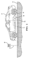
[0014]図2に示される非限定的な例によると、電源装置22、送信機制御器24、および第1の送受信機26は、供給源共振器20から離れて設置された独立した筐体30に収容され得る。この例においては、筐体30は、車両駐車空間の前方のパイロン32またはポストに設置され、一方、供給源共振器20は、車両36の下方の駐車面34の表面または内部に配置される。供給源共振器20が、電源装置22、送信機制御器24、および第1の送受信機26とともに駐車面34の同じ場所に設置される他の実施形態も想定できる。
[0014] According to a non-limiting example shown in FIG. 2, the
[0015]再び図1を参照すると、無線電力受信機16は、供給源共振器20によって生成された磁気信号14によって励起されたとき、交流電流を生成するように構成された共振回路である捕捉共振器38を含む。無線電力受信機16はまた、捕捉共振器38によって供給された交流(AC)電力を、電気自動車(EV)またはハイブリッド電気自動車(HEV)のバッテリパックなどの電気負荷18によって使用可能な直流(DC)電力に変換(整流)する整流回路40も含む。捕捉共振器からのAC電力出力を変化させないまま、AC負荷に供給されるAC電力の周波数および電圧を変更する回路を含むAC電動機などのAC負荷に供給する代替的実施形態も想定できる。無線電力受信機16はまた、整流回路40の出力および制御器50に接続され、制御器50に電力を供給するように構成された電圧調整回路52も含む。
[0015] Referring back to FIG. 1, the
[0016]電圧調整回路52は、整流回路40を介して捕捉共振器38に電気的に結合される入力と、制御器50に電気的に結合される出力とを有する。電圧調整回路52は、捕捉共振器38が電力を供給しているときはいつでも制御器50に電力を供給する。電圧調整回路52は、制御器50に、整流回路40による高電圧出力ではなく制御器50の適切な動作に必要な電圧で、電力を供給するように構成される。制御器50は、電圧調整回路52が制御器50への電力供給を開始すると、「起動」して動作を開始するように構成される。電圧調整回路52は、整流回路40からの高電圧出力を、12ボルト電力を必要とする装置の他の回路が使用可能な電圧に調整する12ボルト調整器、および12ボルト調整器から12ボルトの電力を受信し、調整された5ボルトの電力を、制御器50および5ボルトの電力供給を必要とする他の回路に供給する5ボルト調整器などのいくつかの回路を含み得る。
The
[0017]制御器50は、マイクロプロセッサまたは特定用途向け集積回路(ASIC)を含み得る。無線電力受信機16を制御するように制御器50をプログラムするソフトウェア命令は、不揮発性(NV)メモリ装置51に保存される。メモリ装置51は、マイクロプロセッサまたはASICに含まれてもよく、または個別の装置でもよい。使用され得るNVメモリの種類の非限定的な例は、電気的消去可能プログラマブル読出し専用メモリ(EEPROM)、マスクされた読出し専用メモリ(ROM)、およびフラッシュメモリなどを含む。制御器50はまた、アナログ−デジタル(A/D)変換器回路およびデジタル−アナログ(D/A)変換器回路を含み得、変換器が制御器50の外部の装置と電気通信を確立することを許容する。本明細書において説明される制御器50は、互いに通信しているいくつかのマイクロプロセッサを含み得る。
[0017] The
[0018]無線電力受信機16はまた、これもまた捕捉共振器38の出力と制御器50とに接続され、制御器50によって捕捉共振器38が電力を出力しているかを判定するための入力として使用され得る、電圧検知回路58も含み得る。
[0018] The
[0019]無線電力受信機16は追加的に、捕捉共振器38に電気的に結合され、この例においては整流回路40の出力に直接的に電気的に接続された電圧検知回路58を含む。電圧検知回路58は、整流回路40の出力に高電圧DCがあったときに検知し、制御器50にデジタル信号を送信する。
[0019] The
[0020]典型的には、高電圧回路においては、高電圧に取り付けられる電圧調整器および他の回路は、安全のために絶縁されなければならない。電圧検知回路58の場合は、光結合器が使用される。電圧調整回路52は絶縁変圧器を含み得るが、他の高電圧(HV)絶縁方法が代替的に用いられてもよい。
[0020] Typically, in high voltage circuits, voltage regulators and other circuits attached to the high voltage must be isolated for safety. In the case of the
[0021]無線電力受信機16はまた、無線電力受信機16と無線電力送信機12との間に第1の送受信機26を介して無線通信リンク28を確立するように構成された第2の送受信機62も含む。第2の送受信機62は制御器50と通信している。第2の送受信機62は、電圧調整回路52と電気的に結合され、電圧調整回路52によって電力を供給される。あるいは、バッテリによって電力を供給される車両の電気システムなどの、別個の電源装置によって電力を供給されてもよい。
[0021] The
[0022]典型的には、制御器50は、稼働していないときには、電力消費を最小化するためにスリープまたは非作動状態にある。しかしながら、もしも無線電力送信機12と無線電力受信機16との間に既に電力が流れているとしたら、それは速やかに管理されなければならない。電圧調整回路52は、整流回路40の高電圧出力に接続される。整流回路40が高電圧電力の供給を開始したら即座に、電圧調整回路52は制御器50および無線電力受信機16の残りの回路に電力を供給する。制御器50は電圧調整回路52から供給される電力によって起動され、次いで内的な起動手順を行い、制御器50の全ての入力を確認する。これらの入力のうちの1つは、電圧検知回路58からの論理レベル信号であり得、この倫理レベル信号は、点火スイッチ、他の起動信号、または制御器50がモニタリングしている電源装置によって制御器50が起動されたのか否かを、制御器50が判定するために他の入力とともに使用可能である。制御器50はまた、コントローラエリアネットワーク(CAN)バス66などのデータ通信バス66または他の通信方法を介して、電力がどのように使用されるべきかを判断するために、車両制御器64とも通信し得る。
[0022] Typically, the
[0023]制御器50と送信機制御器24とが無線通信リンク28を介して通信しているとき、制御器50は無線電力送信機12が無線電力受信機16に充電電力を供給することを許可する。無線電力受信機16は、次いで、無線電力送信機12によって送信された電力を調整する。
[0023] When the
[0024]システム10は、無線電力受信機16からではなく無線電力送信機12からの電力伝送を、自動的に開始し得る。無線電力受信機16は、多くの種類の磁場源を自動的に検知し、起動して無線電力送信機12からの電力の調整を開始するために使用することができる。
[0024] The
[0025]かくして、無線電力伝送システム10の捕捉共振器38と電気負荷18との間の電気接続を制御するための無線電力受信機16が提供される。無線電力受信機16の回路は捕捉共振器38からの電力出力によって直接的に電力を供給される。これは、捕捉共振器38が電力の生成を開始し次第、無線電力受信機16を自動的に起動するという利点を提供する。無線電力受信機16は、車両バッテリ18などの外部電源から供給される待機電力を必要としない。無線電力受信機16は外部電源からの電力を必要としないので、無線電力受信機16はまた、車両36のバッテリの充電状態が制御器50を作動するには低すぎるとしても、すなわち、「バッテリが上がっている(dead battery)」状態だとしても、車両バッテリ18の充電を開始できるという利点も提供する。
[0025] Thus, a
[0026]本発明は、その好ましい実施形態に関して説明されたが、本発明はそのように限定されることは意図されておらず、以下の特許請求の範囲に記載された範囲にのみ限定されることが意図される。更に、第1、第2などの用語の使用は、重要度の順番を示すものではなく、第1、第2などの用語は、1つの要素を別の要素から区別するために使用されている。更に、1つの(a、an)などの用語の使用は、量の限定を示すものではなく、言及された物品が少なくとも1つ存在することを示す。 [0026] Although the invention has been described with reference to preferred embodiments thereof, it is not intended that the invention be limited so, but only to the extent described in the following claims. Is intended. Furthermore, the use of terms such as first, second, etc. does not indicate the order of importance, and terms such as first, second, etc. are used to distinguish one element from another. . Furthermore, the use of a term such as (a, an) does not indicate a limitation of quantity, but indicates that there is at least one article mentioned.
Claims (3)
前記交流磁場(14)によって励起されたときに交流電流を生成するように構成された捕捉共振器(38)と、
前記捕捉共振器(38)に電気的に結合され、前記交流電流に励起されたときに直流電流を生成するように構成された整流回路(40)と、
前記無線電力受信機(16)を制御するように構成された制御器(50)と、
前記捕捉共振器(38)および前記制御器(50)に電気的に結合された電圧調整回路(52)とを備え、前記制御器(50)は、前記捕捉共振器(38)が前記交流磁場(14)を受けとっているとき、前記電圧調整回路(52)から電力を受信し、これにより前記制御器(50)を作動させるように構成される、無線電力受信機(16)。 A wireless power receiver (16) configured to receive an alternating magnetic field (14) generated by a wireless power transmitter (12), comprising:
A capture resonator (38) configured to generate an alternating current when excited by the alternating magnetic field (14);
A rectifier circuit (40) electrically coupled to the capture resonator (38) and configured to generate a direct current when excited by the alternating current;
A controller (50) configured to control the wireless power receiver (16);
A voltage regulator circuit (52) electrically coupled to the capture resonator (38) and the controller (50), wherein the controller (50) is configured such that the capture resonator (38) is the alternating magnetic field. (14) A wireless power receiver (16) configured to receive power from the voltage regulator circuit (52) and thereby activate the controller (50) when receiving.
Applications Claiming Priority (3)
| Application Number | Priority Date | Filing Date | Title |
|---|---|---|---|
| US13/895,413 US9369001B2 (en) | 2013-05-16 | 2013-05-16 | Magnetic field detection apparatus for a wireless power transfer system |
| US13/895,413 | 2013-05-16 | ||
| PCT/US2014/036022 WO2014186128A1 (en) | 2013-05-16 | 2014-04-30 | Magnetic field detection apparatus for a wireless power transfer system |
Publications (2)
| Publication Number | Publication Date |
|---|---|
| JP2016524889A true JP2016524889A (en) | 2016-08-18 |
| JP2016524889A5 JP2016524889A5 (en) | 2016-09-29 |
Family
ID=51895234
Family Applications (1)
| Application Number | Title | Priority Date | Filing Date |
|---|---|---|---|
| JP2016513969A Pending JP2016524889A (en) | 2013-05-16 | 2014-04-30 | Magnetic field sensing device for wireless power transfer system |
Country Status (6)
| Country | Link |
|---|---|
| US (1) | US9369001B2 (en) |
| EP (1) | EP2997641A4 (en) |
| JP (1) | JP2016524889A (en) |
| KR (1) | KR20160013862A (en) |
| CN (1) | CN105379050A (en) |
| WO (1) | WO2014186128A1 (en) |
Families Citing this family (29)
| Publication number | Priority date | Publication date | Assignee | Title |
|---|---|---|---|---|
| US9281119B2 (en) * | 2013-11-13 | 2016-03-08 | The Hong Kong Polytechnic University | Three-coil topology for wireless power transfer |
| US9739844B2 (en) * | 2014-07-25 | 2017-08-22 | Qualcomm Incorporated | Guidance and alignment system and methods for electric vehicle wireless charging systems |
| JP6476721B2 (en) * | 2014-10-10 | 2019-03-06 | 株式会社Ihi | Power receiving coil device and non-contact power feeding system |
| CA2974480C (en) * | 2015-01-29 | 2019-04-02 | Nissan Motor Co., Ltd. | Parking assistance device and parking assistance method |
| US10097046B2 (en) | 2016-03-18 | 2018-10-09 | Global Energy Transmission, Co. | Wireless power assembly |
| KR20180132715A (en) * | 2016-03-18 | 2018-12-12 | 글로벌 에너지 트랜스미션, 컴퍼니 | System for wireless power transmission |
| US9662900B1 (en) * | 2016-07-14 | 2017-05-30 | Datamax-O'neil Corporation | Wireless thermal printhead system and method |
| US20200274398A1 (en) * | 2018-05-01 | 2020-08-27 | Global Energy Transmission, Co. | Systems and methods for wireless power transferring |
| CN108556632B (en) * | 2018-06-10 | 2023-08-25 | 重庆三三电器股份有限公司 | Intelligent TFT instrument screen brightness wake-up circuit and control method thereof |
| US11336120B2 (en) * | 2018-12-14 | 2022-05-17 | Otis Elevator Company | Wireless power transfer system for elevators with extended range |
| US10892800B1 (en) | 2020-01-06 | 2021-01-12 | Nucurrent, Inc. | Systems and methods for wireless power transfer including pulse width encoded data communications |
| US11303165B2 (en) | 2020-07-24 | 2022-04-12 | Nucurrent, Inc. | Low cost communications demodulation for wireless power receiver system |
| US11303164B2 (en) | 2020-07-24 | 2022-04-12 | Nucurrent, Inc. | Low cost communications demodulation for wireless power transmission system |
| US11476898B2 (en) | 2021-01-28 | 2022-10-18 | Nucurrent, Inc. | Wireless power transfer system with mode switching using selective quality factor alteration |
| US11316378B1 (en) * | 2021-01-28 | 2022-04-26 | Nucurrent, Inc. | Wireless power receiver with in-band virtualized wired communications |
| US11271611B1 (en) | 2021-01-28 | 2022-03-08 | Nucurrent, Inc. | Wireless power transfer with in-band virtualized wired communications |
| US11483033B2 (en) | 2021-01-28 | 2022-10-25 | Nucurrent, Inc. | Wireless power transfer system with data versus power priority optimization |
| US11418069B1 (en) | 2021-01-28 | 2022-08-16 | Nucurrent, Inc. | Wireless power transfer system with data-priority and power-priority transfer modes |
| US11838076B2 (en) | 2021-01-28 | 2023-12-05 | Nucurrent, Inc. | Wireless power transmitter with in-band virtualized wired communications |
| US11277031B1 (en) * | 2021-02-01 | 2022-03-15 | Nucurrent, Inc. | Automatic gain control for communications demodulation in wireless power transmitters |
| US11277035B1 (en) * | 2021-02-01 | 2022-03-15 | Nucurrent, Inc. | Automatic gain control for communications demodulation in wireless power transmitters |
| US11569694B2 (en) | 2021-02-01 | 2023-01-31 | Nucurrent, Inc. | Automatic gain control for communications demodulation in wireless power receivers |
| US11431205B2 (en) | 2021-02-01 | 2022-08-30 | Nucurrent, Inc. | Systems and methods for receiver beaconing in wireless power systems |
| US11431204B2 (en) | 2021-02-01 | 2022-08-30 | Nucurrent, Inc. | Automatic gain control for communications demodulation in wireless power transfer systems |
| US11811244B2 (en) | 2021-02-01 | 2023-11-07 | Nucurrent, Inc. | Automatic gain control for communications demodulation in wireless power transmitters |
| US11277034B1 (en) * | 2021-02-01 | 2022-03-15 | Nucurrent, Inc. | Systems and methods for receiver beaconing in wireless power systems |
| WO2022165363A1 (en) * | 2021-02-01 | 2022-08-04 | Nucurrent, Inc. | Automatic gain control for communications demodulation in wireless power transfer systems |
| US11754618B2 (en) | 2021-10-15 | 2023-09-12 | Nucurrent, Inc. | Testing device for electronic devices with in-band virtualized wired communications |
| US11626756B1 (en) * | 2021-10-15 | 2023-04-11 | Nucurrent, Inc. | Wireless power and data transfer system with out of band communications hand off |
Citations (4)
| Publication number | Priority date | Publication date | Assignee | Title |
|---|---|---|---|---|
| JPH03210828A (en) * | 1990-01-12 | 1991-09-13 | Omron Corp | Object identification system |
| JPH11341711A (en) * | 1998-05-21 | 1999-12-10 | Sony Corp | Noncontact power supply circuit |
| JP2011229265A (en) * | 2010-04-19 | 2011-11-10 | Panasonic Electric Works Co Ltd | Non-contacting power transmitter |
| JP2013065154A (en) * | 2011-09-16 | 2013-04-11 | Seiko Epson Corp | Circuit device and electronic apparatus |
Family Cites Families (20)
| Publication number | Priority date | Publication date | Assignee | Title |
|---|---|---|---|---|
| US8527046B2 (en) | 2000-04-20 | 2013-09-03 | Medtronic, Inc. | MRI-compatible implantable device |
| KR100792311B1 (en) | 2005-07-30 | 2008-01-07 | 엘에스전선 주식회사 | Rechargeable power supply, rechargeable device, battery device, contactless recharger system and method for charging rechargeable battery cell |
| US8450877B2 (en) * | 2009-01-06 | 2013-05-28 | Access Business Group International Llc | Communication across an inductive link with a dynamic load |
| CN101715261A (en) * | 2009-07-15 | 2010-05-26 | 深圳市泉芯电子技术有限公司 | Status switching circuit of LED controller |
| US8390249B2 (en) * | 2009-11-30 | 2013-03-05 | Broadcom Corporation | Battery with integrated wireless power receiver and/or RFID |
| US9106086B2 (en) | 2010-03-11 | 2015-08-11 | Qualcomm Incorporated | Detection and protection of devices within a wireless power system |
| US8473070B2 (en) | 2010-03-26 | 2013-06-25 | Boston Scientific Neuromodulation Corporation | Method for a controlled shutdown of an implantable medical device |
| CA2801920A1 (en) | 2010-06-10 | 2011-12-15 | Access Business Group International Llc | Coil configurations for inductive power transfer |
| EP2580844A4 (en) * | 2010-06-11 | 2016-05-25 | Mojo Mobility Inc | System for wireless power transfer that supports interoperability, and multi-pole magnets for use therewith |
| KR101859191B1 (en) | 2011-03-23 | 2018-05-18 | 삼성전자주식회사 | Method and apparatus for controlling wireless power transmission and reception, and wireless power transmission system |
| KR101850527B1 (en) | 2011-03-25 | 2018-04-19 | 삼성전자주식회사 | Portable Device and Wireless Power Charging system |
| US10090885B2 (en) | 2011-04-13 | 2018-10-02 | Qualcomm Incorporated | Antenna alignment and vehicle guidance for wireless charging of electric vehicles |
| US9199545B2 (en) | 2011-06-01 | 2015-12-01 | Samsung Electronics Co., Ltd. | Method and apparatus for controlling wireless power transmission |
| JP2012257395A (en) | 2011-06-09 | 2012-12-27 | Toyota Motor Corp | Non-contact power reception device, vehicle having the same, non-contact transmission device, and non-contact power transmission system |
| JP2013070580A (en) * | 2011-09-26 | 2013-04-18 | Sony Corp | Power receiving device, power transmitting device, wireless power transfer system, and wireless power transfer method |
| JP2013078171A (en) | 2011-09-29 | 2013-04-25 | Semiconductor Energy Lab Co Ltd | Power receiving device and non-contact power supply system |
| US8483899B2 (en) | 2011-10-06 | 2013-07-09 | Ford Global Technologies, Llc | Vehicle guidance system |
| JP5657148B2 (en) * | 2012-01-25 | 2015-01-21 | 三菱電機株式会社 | Optical receiver, station side optical termination device, and received light level monitoring method |
| US9934902B2 (en) * | 2012-12-05 | 2018-04-03 | Samsung Electronics Co., Ltd. | Apparatus and method for transceiving wireless power |
| US20140191568A1 (en) * | 2013-01-04 | 2014-07-10 | Mojo Mobility, Inc. | System and method for powering or charging multiple receivers wirelessly with a power transmitter |
-
2013
- 2013-05-16 US US13/895,413 patent/US9369001B2/en active Active
-
2014
- 2014-04-30 JP JP2016513969A patent/JP2016524889A/en active Pending
- 2014-04-30 KR KR1020157032258A patent/KR20160013862A/en not_active Application Discontinuation
- 2014-04-30 EP EP14797733.4A patent/EP2997641A4/en not_active Withdrawn
- 2014-04-30 CN CN201480028128.7A patent/CN105379050A/en active Pending
- 2014-04-30 WO PCT/US2014/036022 patent/WO2014186128A1/en active Application Filing
Patent Citations (4)
| Publication number | Priority date | Publication date | Assignee | Title |
|---|---|---|---|---|
| JPH03210828A (en) * | 1990-01-12 | 1991-09-13 | Omron Corp | Object identification system |
| JPH11341711A (en) * | 1998-05-21 | 1999-12-10 | Sony Corp | Noncontact power supply circuit |
| JP2011229265A (en) * | 2010-04-19 | 2011-11-10 | Panasonic Electric Works Co Ltd | Non-contacting power transmitter |
| JP2013065154A (en) * | 2011-09-16 | 2013-04-11 | Seiko Epson Corp | Circuit device and electronic apparatus |
Also Published As
| Publication number | Publication date |
|---|---|
| EP2997641A1 (en) | 2016-03-23 |
| US9369001B2 (en) | 2016-06-14 |
| CN105379050A (en) | 2016-03-02 |
| WO2014186128A1 (en) | 2014-11-20 |
| US20140339923A1 (en) | 2014-11-20 |
| EP2997641A4 (en) | 2017-01-11 |
| KR20160013862A (en) | 2016-02-05 |
Similar Documents
| Publication | Publication Date | Title |
|---|---|---|
| JP2016524889A (en) | Magnetic field sensing device for wireless power transfer system | |
| US9333864B2 (en) | Wake-by-control pilot circuit for onboard battery charger | |
| CN103119823B (en) | Battery charge controller and charging system | |
| US10418859B2 (en) | Control apparatus | |
| KR20120023750A (en) | Electric vehicle | |
| KR101523158B1 (en) | Recharging device for vehicle | |
| WO2013054435A1 (en) | Electric vehicle charging device | |
| EP2910407A2 (en) | Connection detecting device for electric vehicle charger | |
| US20160111908A1 (en) | Power supply apparatus for electric vehicle and method of controlling the same | |
| US20200094703A1 (en) | Vehicle charging system | |
| US20160311338A1 (en) | Device and Method for the Supply of Emergency Power to at Least One Electrical Load | |
| CN115149611A (en) | Bidirectional charging system for electric vehicle | |
| KR101619618B1 (en) | Vehicle charger and method for controlling power thereof | |
| KR20180087014A (en) | Battery pack, management method of the same, and vehicle comprisin the same | |
| CN104737407A (en) | Power supply system and method for an electric vehicle | |
| EP3038853B1 (en) | Charging system and pairing method | |
| KR20190130937A (en) | Control method of reservation-based charging device for vehicle | |
| JP2008236968A (en) | Noncontact power transmitter | |
| US20150372519A1 (en) | Charging and discharging device | |
| JPWO2014068782A1 (en) | vehicle | |
| CN110014889B (en) | Power supply for a low-voltage on-board network of a vehicle having an electric drive | |
| JP5220078B2 (en) | In-vehicle charging / discharging device | |
| JP2007336787A (en) | Contactless power supply system, power supply device, and power receiving device | |
| JP2016010246A (en) | Charging/discharging device for electric vehicle, charging/discharging system for electric vehicle, and operation method of charging/discharging system for electric vehicle | |
| JP2018074753A (en) | Charge and discharge device |
Legal Events
| Date | Code | Title | Description |
|---|---|---|---|
| A521 | Request for written amendment filed |
Free format text: JAPANESE INTERMEDIATE CODE: A523 Effective date: 20160712 |
|
| A621 | Written request for application examination |
Free format text: JAPANESE INTERMEDIATE CODE: A621 Effective date: 20160712 |
|
| A871 | Explanation of circumstances concerning accelerated examination |
Free format text: JAPANESE INTERMEDIATE CODE: A871 Effective date: 20160712 |
|
| A975 | Report on accelerated examination |
Free format text: JAPANESE INTERMEDIATE CODE: A971005 Effective date: 20160826 |
|
| A131 | Notification of reasons for refusal |
Free format text: JAPANESE INTERMEDIATE CODE: A131 Effective date: 20160830 |
|
| A521 | Request for written amendment filed |
Free format text: JAPANESE INTERMEDIATE CODE: A523 Effective date: 20161130 |
|
| A02 | Decision of refusal |
Free format text: JAPANESE INTERMEDIATE CODE: A02 Effective date: 20170117 |