JP2016515066A - Electro-optic mirror system and method - Google Patents
Electro-optic mirror system and method Download PDFInfo
- Publication number
- JP2016515066A JP2016515066A JP2016501295A JP2016501295A JP2016515066A JP 2016515066 A JP2016515066 A JP 2016515066A JP 2016501295 A JP2016501295 A JP 2016501295A JP 2016501295 A JP2016501295 A JP 2016501295A JP 2016515066 A JP2016515066 A JP 2016515066A
- Authority
- JP
- Japan
- Prior art keywords
- electro
- optic
- rearview mirror
- photosensor
- mirror assembly
- Prior art date
- Legal status (The legal status is an assumption and is not a legal conclusion. Google has not performed a legal analysis and makes no representation as to the accuracy of the status listed.)
- Pending
Links
Images


Classifications
-
- B—PERFORMING OPERATIONS; TRANSPORTING
- B60—VEHICLES IN GENERAL
- B60R—VEHICLES, VEHICLE FITTINGS, OR VEHICLE PARTS, NOT OTHERWISE PROVIDED FOR
- B60R1/00—Optical viewing arrangements; Real-time viewing arrangements for drivers or passengers using optical image capturing systems, e.g. cameras or video systems specially adapted for use in or on vehicles
- B60R1/02—Rear-view mirror arrangements
- B60R1/08—Rear-view mirror arrangements involving special optical features, e.g. avoiding blind spots, e.g. convex mirrors; Side-by-side associations of rear-view and other mirrors
- B60R1/083—Anti-glare mirrors, e.g. "day-night" mirrors
- B60R1/088—Anti-glare mirrors, e.g. "day-night" mirrors using a cell of electrically changeable optical characteristic, e.g. liquid-crystal or electrochromic mirrors
-
- B—PERFORMING OPERATIONS; TRANSPORTING
- B60—VEHICLES IN GENERAL
- B60R—VEHICLES, VEHICLE FITTINGS, OR VEHICLE PARTS, NOT OTHERWISE PROVIDED FOR
- B60R1/00—Optical viewing arrangements; Real-time viewing arrangements for drivers or passengers using optical image capturing systems, e.g. cameras or video systems specially adapted for use in or on vehicles
- B60R1/12—Mirror assemblies combined with other articles, e.g. clocks
- B60R2001/1223—Mirror assemblies combined with other articles, e.g. clocks with sensors or transducers
Landscapes
- Engineering & Computer Science (AREA)
- Multimedia (AREA)
- Mechanical Engineering (AREA)
- Chemical & Material Sciences (AREA)
- Crystallography & Structural Chemistry (AREA)
- Electrochromic Elements, Electrophoresis, Or Variable Reflection Or Absorption Elements (AREA)
- Rear-View Mirror Devices That Are Mounted On The Exterior Of The Vehicle (AREA)
Abstract
システムは、後続車両からのグレアを減少するように構成される。このシステムは、内部ミラー筐体に部分的に囲まれた前方光センサを備えてもよい。この前方光センサは、システムが昼間条件および夜間条件を決定することができるように、周囲光を検出するように構成されている。このシステムは、別々のミラーアセンブリに各々が含まれる複数の後向き光センサを備えてもよい。検知された周囲光および後続車両のグレアに基づいて、システムは、別個のミラーアセンブリ内で個別にグレアを減少するために、電気光学素子の反射率を変更するように、構成されてもよい。The system is configured to reduce glare from the following vehicle. The system may include a front light sensor partially surrounded by an internal mirror housing. The front light sensor is configured to detect ambient light so that the system can determine daytime and nighttime conditions. The system may comprise a plurality of rearward light sensors, each included in a separate mirror assembly. Based on the sensed ambient light and the glare of the following vehicle, the system may be configured to change the reflectivity of the electro-optic element to reduce glare individually within a separate mirror assembly.
Description
本発明は、概ねバックミラーシステムに関し、より詳しくは電気光学バックミラーシステムに関する。 The present invention relates generally to rearview mirror systems, and more particularly to electro-optic rearview mirror systems.
本発明の一態様によれば、システムは、後続車両からのグレアを減少させるように構成されている。このシステムは、内部ミラー筐体に部分的に囲まれた前向き光センサを具備する。前向き光センサは、システムが昼間条件または夜間条件を決定することができるように、周囲光を検出するように構成されている。また、このシステムは、別々のミラーアセンブリに各々が含まれる複数の後向きグレアセンサまたは光センサを具備している。後続車両の検知されたグレアに基づいて、システムはグレアを少なくする各々のミラーモジュールアセンブリにおける電気光学素子の反射率を変更するように、構成されている。 According to one aspect of the invention, the system is configured to reduce glare from the following vehicle. The system includes a forward light sensor partially surrounded by an internal mirror housing. The forward light sensor is configured to detect ambient light so that the system can determine daytime or nighttime conditions. The system also includes a plurality of rear-facing glare sensors or light sensors, each contained in a separate mirror assembly. Based on the detected glare of the following vehicle, the system is configured to change the reflectivity of the electro-optic element in each mirror module assembly that reduces glare.
本発明の別の態様によれば、外部電気光学ミラーアセンブリは、車両で使用されるように構成されている。外部電気光学ミラーアセンブリは、第1の基板と、この第1の基板にほぼ平行な第2の基板とを備えてもよい。第1の基板および第2の基板は、電気光学素子を受けるように構成された空隙部を画成してもよい。第1の光センサは光を検出するように構成され、車両の後方に少なくとも部分的に視野を有してもよい。プロセッサは第2の光センサから入力信号を受け取るように構成されてもよい。さらに、プロセッサは、光センサによって検出された光と第2の光センサからの受信入力とに応答して電気光学素子に供給される電力を制御するように、構成されてもよい。 According to another aspect of the invention, the external electro-optic mirror assembly is configured for use in a vehicle. The external electro-optic mirror assembly may include a first substrate and a second substrate that is substantially parallel to the first substrate. The first substrate and the second substrate may define a gap configured to receive the electro-optic element. The first light sensor may be configured to detect light and may have a field of view at least partially behind the vehicle. The processor may be configured to receive an input signal from the second photosensor. Further, the processor may be configured to control the power supplied to the electro-optic element in response to the light detected by the photosensor and the received input from the second photosensor.
本発明のこれらおよびその他の特徴、利点、および目的は、以下の明細書、特許請求の範囲、および添付図面を参照により、当業者によってさらに理解および認識される。 These and other features, advantages, and objects of the present invention will be further understood and appreciated by those skilled in the art by reference to the following specification, claims, and appended drawings.
本発明は、詳細な説明および添付図面から、より完全に理解される。
図示した本発明の実施形態は、電気光学ミラーシステムに関する方法ステップと装置構成要素との組み合わせに、主として属する。したがって、装置構成素子および方法ステップが説明されており、必要に応じて図中の慣習的な符号により、本発明の実施形態の理解に関係のある特定の詳細のみを示すことで、当業者が容易に理解して本明細書中の説明の利益を得るであろう詳細な開示が不明瞭にならないようにする。さらに、説明および図面にある同様の数字は同様の素子を表す場合がある。 The illustrated embodiments of the present invention primarily belong to the combination of method steps and apparatus components for an electro-optic mirror system. Accordingly, apparatus components and method steps have been described, and those of ordinary skill in the art will be able to provide only specific details relevant to an understanding of embodiments of the present invention, where appropriate, with conventional reference numerals in the figures. The detailed disclosure, which will be readily understood and will benefit from the description herein, should not be obscured. Moreover, like numbers in the description and drawings may represent like elements.
この明細書では、関連する用語、例えば、第1および第2、上および下などは、1つの構成素子または動作を他の構成素子または動作と区別するために、単独で用いられるもので、そのような複数の構成素子または動作の間での実際の相互関係または順序を必ずしも要求または包含するものではない。用語「含む("comprises"、"comprising")」またはその用語の他のバリエーションは、列挙される複数の要素を含むプロセス、方法、物品、または装置がそれらの要素のみを含むものではなく、はっきりと列挙されていない、またはそのようなプロセス、方法、物品、もしくは装置にとって固有のものではない他の要素を含んでもよいように、非排他的包含を範囲とすることを意図している。「〜を具備する("comprses…a")」に先行する素子は、その素子を具備するプロセス、方法、物品、または装置において同一の素子が追加されて存在することを、制限されることなく、除外するものではない。 In this specification, related terms, such as first and second, top and bottom, etc., are used solely to distinguish one component or operation from another component or operation. The actual interrelationship or order between such components or operations is not necessarily required or encompassed. The term “comprises”, “comprising” or other variations of the term does not mean that a process, method, article, or apparatus that includes a plurality of listed elements includes only those elements. It is intended to cover non-exclusive inclusions so that they may include other elements that are not listed as such or that are not inherent to such processes, methods, articles, or devices. An element preceding "comprises ... a" is not limited to the presence of additional identical elements in the process, method, article, or apparatus comprising the element , Not exempt.
図1に関して、電気光学ミラーシステムは、参照符号100で概ね示される。システム100は、第1のミラーアセンブリ102(例えば電気光学内部ミラーアセンブリ)を具備してもよい。さらに、システム100は、第2のミラーアセンブリ104aと、第3のミラーアセンブリ104bとを具備してもよい。第2のミラーアセンブリ104aおよび第3のミラーアセンブリ104bは、それぞれ、運転手側外部ミラーアセンブリおよび乗客側外部ミラーアセンブリを具備してもよい。
With reference to FIG. 1, an electro-optic mirror system is indicated generally by the
ミラーアセンブリ102、104a、104bはそれぞれ、受けた光(例えばグレア光)を検出するように構成された後向き光センサ106a、106b、106dを具備してもよい。グレア光は、1つまたは複数の後続車両の少なくとも1つのヘッドライトから放射される光に相当することがある。後向き光センサ106a、106b、および106d の各々は、ミラーアセンブリ102、104a、および104bの各々において、プロセッサ108a、108b、および108cと連通するように構成されてもよい。受信した光に応答して、後向き光センサ106a、106b、および106dの各々は、各々のプロセッサ108a、108b、および108cへ信号を通信してもよい。
Each of the
プロセッサ108a、108b、および108cは、後向き光センサ106a、106b、および106dから受信された信号の各々からの光強度を決定するように、作動可能であってもよい。さらに、プロセッサ108a、108b、および108cの各々は、ミラーアセンブリ102、104a、および104bの各々の駆動回路110a、110b、および110cと連通し、かつそれらを制御するように作動可能であってもよい。さらに、各々の駆動回路110a、110b、および110cは、ミラーアセンブリ102、104a、および104bに各々の可変反射率ミラー素子112a、112b、および112cと電気的に連通してもよい。プロセッサ108a、108b、および108cの各々からの制御信号に応答して、駆動回路110a、110b、および110cは、可変反射率ミラー素子112a、112b、および112cの各々の反射率レベルを制御してもよい。各々のプロセッサ108a、108b、および108cの制御信号に応答して、可変反射率ミラーアセンブリ102、104a、および104bの各々は、反射率レベルを個々に変化させるように作動可能であってもよい。
The
例えば、第1の後向き光センサ106aはグレア光を検知し、プロセッサ108aへグレア光に対応する信号を通信してもよい。信号に応答して、プロセッサ108aは、グレア光の強度を決定するよう作動可能であってもよい。グレア光の強度にもとづいて、プロセッサ108aは、反射率、または、可変反射率ミラー素子112aの反射率レベルを制御してもよい。可変反射率ミラー素子112aの反射率を制御するために、プロセッサ108aは、駆動回路110aへの制御信号を送信してもよい。制御信号に応答して、駆動回路は、後向き光センサ106aによって検知されたグレア光に基づいた可変反射率ミラー素子112aの反射率レベルを制御するよう作動可能であってもよい。
For example, the first backward
ミラーアセンブリ102、104a、および104b(例えば内部バックミラーアセンブリ102)の少なくとも1つは、さらに第4の光センサ(例えば前向き光センサ106c)を具備してもよい。前向き光センサ106cは、一般に車両の通常運転方向に対して前方向を向いてもよい。前向き光センサ106cは、周囲光を受信するように構成されてもよく、それによってシステム100が周囲照明条件を決定可能になる。周囲照明条件は、任意の照明条件を含んでもよく、光源から上に、または、車両からいくらか前方に放射された光に概ね対応してもよい。例えば、周囲照明条件は、昼間照明条件または夜間照明条件などの周囲の光強度を有してもよい。
At least one of the
前向き光センサ106cは、プロセッサ108a、108b、および108cの1つまたは複数と電気的に連通してもよい。例示的な実施形態では、前向き光センサ106cは、内部ミラーアセンブリ102に組み込まれてもよく、またプロセッサ108bと連通してもよい。内部ミラーアセンブリ102のプロセッサ108bとプロセッサ108a、108cの外部のミラーアセンブリ104aおよび104bとは、データリンク114aおよび114bを介して通信するように、さらに作動可能であってもよい。データリンク114aおよび114bは周囲光信号を通信するのに、あるいは、前向き光センサ106cまたはプロセッサ108bからプロセッサ108aおよび108cの各々へ制御信号を通信するのに作動可能であってもよい。
The forward light sensor 106c may be in electrical communication with one or more of the
1つの特定の例において、前向き光センサ106cによって受信された光に基づいた信号は、各々の後向き光センサ106a、106b、106dによって受信された光またはグレア光に基づいた信号と組み合わせられて、プロセッサ108a、108b、および108cの各々によって実行されてもよい。前向き光センサ106cに対応する受信された信号と、後向き光センサ106a、106b、および106dの各々から受信された信号またはグレア光信号とに基づいて、プロセッサ108a、108b、および108cの各々は、可変反射率ミラー素子112a、112b、および112cの反射率レベルを、それぞれ独立して、制御してもよい。
In one particular example, the light based signal received by the forward light sensor 106c is combined with the light or glare light based signal received by each of the backward
この実装で実証されたミラーアセンブリ102、104a、および104bの各々はプロセッサ108a、108b、および108cを含むが、シングルプロセッサは、可変反射率ミラー素子112a、112b、および112cの各々の駆動回路110a、110b、および110cを部分的または全体的に制御するように作動可能であってもよい。ミラーアセンブリ102、104a、および104bの各々が連通しているものとして示されるため、様々な実装には、本開示の精神の範囲内で、単一のプロセッサまたは複数のプロセッサの任意の組み合わせによって、プロセッサ108a、108b、および108cの間で伝達された様々な信号の処理が含まれてもよい。例えば、プロセッサ108bは、前向き光センサ106cからの周囲光の強度を決定し、プロセッサ108aおよび108cの各々に周囲光信号を伝達してもよい。周囲光信号はプロセッサ108aおよび108cを用いて、可変反射率ミラー素子112aおよび112cの反射率を制御してもよい。このように、プロセッサ108aおよび108cは、前向き光センサ106cによって検知された周囲光に対応するプロセッサ108bからの制御信号(例えば、周囲光信号)に応答してもよい。
Each of the
1つの実施形態によれば、通信結合部114aおよび114bは一方向の通信リンクである。いくつかの実装では、通信結合部114aおよび114bは配線接続である。しかしながら、通信結合部114aおよび114bは、少なくとも1つの通報信号を伝送するように作動可能な任意の通信方式によって実装されてもよい。例えば、通信結合部114aおよび114bは、限定されるものではないが、Wi−Fi、RF、IR、ブルートゥース、その他同種のもの、またはそれの任意の組み合わせ等の無線接続によって実装されてもよい。通信結合部114aおよび114bが双方向接続リンクであってもよいことは、当業者であれば当然理解しうる。 According to one embodiment, the communication couplings 114a and 114b are unidirectional communication links. In some implementations, the communication couplings 114a and 114b are wired connections. However, the communication couplings 114a and 114b may be implemented by any communication scheme operable to transmit at least one notification signal. For example, the communication coupling units 114a and 114b may be implemented by a wireless connection such as, but not limited to, Wi-Fi, RF, IR, Bluetooth, or the like, or any combination thereof. A person skilled in the art can naturally understand that the communication coupling portions 114a and 114b may be bidirectional connection links.
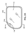
図2Aに示された実施形態を参照すると、外部バックミラーアセンブリ、例えば、運転手側外部ミラーアセンブリ104aの正面図が示される。運転手側外部ミラーアセンブリ104aはミラー筐体120を具備してもよく、それは可変反射率ミラー112aを少なくとも部分的に囲んでいる。また、外部バックミラーアセンブリ104aは後向き光センサ106aを具備してもよい。後向き光センサ106aは、ミラー素子112aの少なくとも1つの基板の後ろに置かれてもよい。また、プロセッサ108aおよび駆動回路110aも、可変反射率ミラー112aの後ろのミラー筐体120に囲まれた運転手側外部ミラーアセンブリ104aに組み込まれてもよい。
Referring to the embodiment shown in FIG. 2A, a front view of an external rearview mirror assembly, eg, a driver side
ミラー素子112aの少なくとも1つの基板は、実質的に並列の第1の基板および第2の基板を具備してもよい。第1の基板と第2の基板は空隙部を画成してもよい。エレクトロクロミック媒体は、空隙部に配置され、少なくとも1つの可変反射率素子の可変反射率を生じるように、作動可能であってもよい。本明細書中で議論されるようなエレクトロクロミック媒体に関するさらなる詳細は、開示の後続部分に見いだされる。
At least one substrate of the
後向き光センサ106aは、可変反射率ミラーの領域を通って、光(例えばグレア光)を検知するように作動可能であってもよい。例えば、可変反射率ミラー112aは、光が可変反射率ミラー112aを通り抜け可能にするように構成された部分116を具備してもよく、この部分116を通り抜ける光を後向き光センサが検知可能になるようにする。いくつかの実装では、部分116は、可変反射率ミラーの表面の全体または表面の一部にわたって半透過型であってもよい。さらに、上記部分116は、光が可変反射率ミラー112aを通り抜けることを可能にするように構成された複数のスリットまたはシースルー部分を有する、窓部分または遮蔽部分を具備してもよい。これらの構成では、後向き光センサ106aは、後続車両からのグレア光の存在や強度を検知するように、作動可能であってもよい。
The backward
図2Bを参照すると、運転手側外部ミラーアセンブリ104aの横断面図が示されている。運転手側外部ミラーアセンブリ104aは、可変反射率ミラー112aの可変反射率表面122を、概ね具備してもよい。可変反射率ミラー112aは、キャリアプレート124によって部分的に囲まれ、かつ支持されてもよい。可変反射率表面122の後ろで、可変反射率表面122の部分116が、光センサ窓部118を光が通り抜け可能になるように、構成されてもよい。いくつかの実装では、汚れおよび破片から後向き光センサ106aを保護するために、後向き光センサ106aは可変反射率ミラー素子112aの後ろに位置してもよい。
Referring to FIG. 2B, a cross-sectional view of the driver side
後向き光センサ106aは、後続車両の少なくとも1つのヘッドライトから光量またはグレア光の強度を読取るように構成される。後向き光センサ106aによって検知されたグレア光の強度に応じて、光センサ106aは、強度を識別する信号をプロセッサ108aに伝達してもよい。制御回路110aと通信するための制御信号を決定するために、後向き光センサ106aからの信号はプロセッサ108aによって分析されてもよい。プロセッサ108aからの制御信号に基づいて、制御回路110aは、可変反射ミラー素子112aの可変反射率表面122の反射率レベルを制御するように構成されてもよい。
The
典型的な実装では、さらに、プロセッサは通信結合部114aからの信号を受け取るように、作動可能であってもよい。通信結合部は、前向き光センサ106cによって検知された少なくとも1つの周囲光信号を送信してもよい。後向き光センサ106aからの信号と前向き光センサ106cからの信号との組み合わせに応じて、プロセッサは、可変反射率表面122の反射率レベルを制御してもよい。例えば、前向き光センサ106cから送信された暗所または夜間条件と後向き光センサ106aによって検知されたグレア光とに応答して、プロセッサは、可変反射率表面122の反射率レベルを減少させてもよい。
In a typical implementation, the processor may be further operable to receive a signal from communication coupling 114a. The communication coupling unit may transmit at least one ambient light signal detected by the forward light sensor 106c. Depending on the combination of the signal from the backward
本明細書中で議論された後向き光センサ106a、106b、および106dの1つまたは複数の様々な実装は、視野に影響する二次光学部品を、さらに具備してもよい。例えば、外部ミラーアセンブリ104aおよび104b上の後向き光センサ106aおよび106dは、二次光学部品を具備してもよく、その際、該二次光学部品が、それぞれの後向き光センサ106aおよび106dの各々の原点または光軸に対して水平視野が約10度外側および約35度内側になるようにする。さらに、または、二者択一的に、外部ミラーアセンブリ104aおよび104bの後向き光センサ106aおよび106dは、センサ原点または光軸、例えば、後向き光センサ106aおよび106dの各々の原点よりも、約10度下および約15度上の、垂直視野をモニターするように構成されてもよい、
Various implementations of one or more of the rear facing
上述の視野は、後向き光センサ106aおよび106dの各々のおよび同一平面感知面および可変反射率表面122が車両に対して垂直でありかつ車両が置かれている道路または面に対して垂直であるように、所定の位置に設けられたミラーアセンブリ104aおよび104bの各々に対応してもよい。従って、後向き光センサ106aおよび106dの各々の視野の中心は、車両の後部の方向とほぼ平行である。特定の視野が本明細書中に詳細に議論されるが、後向き光センサ106aおよび106dの視野は、本開示の精神の範囲内において、垂直方向および水平方向の両方で、10から20度変動してもよい。
The above field of view is such that each of the rear facing
図3および図4に示された実装に関して、内部ミラーアセンブリ102は、少なくとも部分的に可変反射率ミラー素子112bを囲むのに適した筐体126を具備してもよい。内部ミラーアセンブリ102は、車両のフロントガラスまたはヘッドライナーに作動可能に接続するように構成されたマウント128を、具備するようにしてもよい。内部バックミラーアセンブリ102は、筐体126に組み込まれた前向き光センサ106cをさらに具備してもよい。いくつかの実装では、前向き光センサ106cは、車両の後部位置(例えば、内部ミラーアセンブリが設けられるヘッドライナー制御コンソール)に位置決めされてもよい。そのような実装では、前向き光センサ106cは、内部ミラーアセンブリ102の駆動回路またはプロセッサと通信するように、作動可能であってもよい。
With respect to the implementation shown in FIGS. 3 and 4, the
前向き光センサ106cは環境または周囲光の条件(例えば周囲の光強度、照明環境、または他の外部周囲照明条件の明るさ)を検知するように構成されてもよい。周囲光条件には、走行条件(例えば昼間走行条件、夜間走行時間)が含まれてもよい。前向き光センサ106cは、さらにプロセッサ108bと連通してもよい。周囲光の検出または周囲光の強度レベルに応じて、前向き光センサ106cは対応する信号をプロセッサ108bに送信してもよい。周囲光条件に対応する信号に応じて、プロセッサ106bは、システム100が照明条件を決定できるように、周囲光条件を送信してもよい。照明条件に基づいて、システム100は、可変反射率ミラー素子112a、112b、および112cの各々の反射率を、選択的に調節してもよい。
The forward light sensor 106c may be configured to detect environmental or ambient light conditions (eg, ambient light intensity, lighting environment, or brightness of other external ambient lighting conditions). Ambient light conditions may include travel conditions (eg daytime travel conditions, nighttime travel time). The forward light sensor 106c may further communicate with the processor 108b. Depending on the detection of ambient light or the intensity level of ambient light, the forward light sensor 106c may send a corresponding signal to the processor 108b. In response to the signal corresponding to the ambient light condition, the
さらに、内部ミラーアセンブリ102は、後向き光センサ106bを具備してもよい。後向き光センサ106bは、後続車両の少なくとも1つのヘッドライトからのグレア光を検知するように、構成されてもよい。運転中、前向き光センサ106cは、周囲光量(例えば低光量条件または夜間走行条件)を検知するように、作動可能であってもよい。さらに、後向き光センサ106bは、後続車両からのグレア光を検知してもよい。グレア光と組み合わさった低周囲光条件に応答して、プロセッサ108bは、可変反射率ミラー素子112bの反射率が減少するように、可変反射率ミラー素子112bを制御してもよい。図5および6を参照しながらさらに考察するとおり、ミラーアセンブリ102、104a、および104bの各々は、前向き光センサ106cによって検知された周囲条件と、後向き光センサ106a、106b、および106dの各々に検知されたグレア光条件に対して、個別に応答してもよい。
Further, the
動作中のシステム100の一例を図5に示すが、システム100を含む制御された車両のバックミラーアセンブリには、一定量のグレアが存在する。さらに、周囲光または環境照明強度は、前向き光センサ106cによって検知されてもよい。図5および6に関して説明された例では、前向き光センサは低周囲光または夜間条件を検知する。低光条件に応じて、前向き光センサ106cはバックミラーアセンブリのプロセッサ108a、108b、および108cの各々に周囲光信号を送信してもよい。後向き光センサ106a、106b、および106dの少なくとも1つによって検知されたグレア光に応答して、反射率レベルの減少を促進するべく、周囲光信号は、プロセッサ108a、108b、および108cの各々と通信してもよい。
An example of a
当該の例において、後続車両142は、後続車両142の少なくとも1つのヘッドライトからのグレア146が先行車両144のバックミラーアセンブリ102、104a、および104bの各々に到達可能なように、制御された車両(例えば、先行車両144)の真後ろにある。各々の光センサ106a、106b、106dは、後続車両142からグレア146に対応するグレア量を検知してもよい。受信されたグレアの量に応じて、可変反射率ミラー素子112a、112b、および112cの各々の反射率レベルはプロセッサ108a、108b、および108cの各々によって下げられてもよい。受信されたグレアの量に基づいて、プロセッサの各々は、ミラーアセンブリ102、104a、および104bの反射率レベルを下げるために、可変反射率ミラー素子112a、112b、および112cをそれぞれ別個に暗くしてもよい。反射率レベルの減少によって、先行車両144の乗員に反射されたグレアの量を低減されることがある。
In this example, the following
後向き光センサ106a、106b、および106dの各々は、視野152、154、および156を持つように構成されてもよい。視野152、154、および156の各々は、先行車両144のまわりに位置した、別個の暗くなるゾーンに設けられるように、構成されてもよい。後続車両142が先行車両144に接近するにつれて、グレア光は、それぞれの視野152、154、および156の各々にある光センサ106a、106b、および106dの各々によって、受信されてもよい。受信された光あるいは視野152、154、および156の各々に検知されたグレア光に応じて、ミラーアセンブリ102、104a、および104bの各々が結果的に暗くなるように構成されてもよい。このように、システムは、可変性反射素子112a、112b、および112cの反射率を変えるための、独立した複数のゾーンを提供する。
Each of the rear facing
動作中のシステム100の一例も図6に示すが、この例では、一定量のグレアが先行車両144の少なくとも1つのバックミラーアセンブリの中に存在する。後続車両142が先行車両144を追い越している、または、それに対して隣のレーンにいる場合、後続車両142の少なくとも1つのヘッドライトからのグレア146は、部分的に各々のバックミラーアセンブリ102、104a、および104bに達してもよい。この例において、バックミラーアセンブリ104aは、グレア光の第1のレベルを検知してもよい。バックミラーアセンブリ102は、グレア光の第2のレベルを検知してもよい。また、バックミラーアセンブリ104bは、グレア光の第3のレベルを検知してもよい。すなわち各々の後向き光センサ106a、106b、106dは、後続車両142からの異なるレベルのグレア光を受信してもよい。
An example of an
検知されたグレア光の各レベルに応じて、プロセッサ108a、108b、および108cの各々は、可変反射率ミラー素子112a、112b、および112cの各々の反射率レベルの変更を開始してもよい。後向き光センサ106a、106b、および106dの各々は、プロセッサ108a、108b、および108cに信号を送信してもよい。プロセッサ108a、108b、および108cは、駆動回路110a、110b、および110cにそれぞれの可変反射率ミラー素子112a、112b、および112cの各々の反射率を減少させることによって、信号に応答してもよい。可変反射率ミラー素子112a、112b、および112cの反射率を減少させるか暗くすることで、後続車両からのグレアの量を減らして先行車両144のドライバーの視程を改善してもよい。
Depending on the detected level of glare light, each of the
既に論じられたように、後向き光センサ106a、106b、および106dの各々は異なる視野152、154、および156を有するように示されている。後続車両142が先行車両144を追い越すとき、グレア146は各々の視野152、154、および156に不均等に分配されることがある。後向き光センサ106a、106b、および106dの各々によって検知されるグレアのレベルに応答して、各々のミラー102、104a、および104bは結果として暗くなるように構成されてもよい。例えば、ミラーアセンブリ104aおよび対応の後向き光センサ106aは、視野154におけるグレア146の第1のレベルを受信してもよい。内部ミラーアセンブリ156および対応の後向き光センサ106bは、第2の視野156おけるグレア146の第2のレベルを受信してもよい。第1のレベルおよびグレア146の第2のレベルは、強度において異なってもよい。
As previously discussed, each of the rear facing
検知されたグレア146の第1のレベルに応じて、可変反射率ミラー素子112aが第1の減少反射率レベルまで減少されてもよい。検知されたグレア146の第2のレベルに応じて、可変反射率ミラー素子112bは第2の減少反射率レベルまで減少されてもよい。さらに、ミラーアセンブリ104aおよび対応の後向き光センサ106dは、任意のレベルのグレア146を検知しなくてもよいし、受信しなくてもよい。この例において、第1の減少反射率は第2の減少反射率よりも多く減少されてもよい。さらに、可変反射率ミラー素子112cの反射率は、グレア146に対応して検出された光の不足により減少されなくてもよい。このように、システム100は、可変反射率ミラー素子112a、112b、および112cの各々の反射率レベルを個別に制御してもよい。
Depending on the sensed first level of
図7を参照すると、電気光学バックミラーシステムを制御する方法を参照符号200で概ね示す。方法200は、ステップ202で開始されてステップ204へ進み、ここで光が検出される。通常、周囲光は前向き光センサ106cによって検知され、そしてグレア光(例えば後続車両からの光)は後向き光センサ106a、106b、および106dによって検知される。ステップ206では、検知された周囲光に対応するデータは、周囲光信号の形で、プロセッサ108a、108b、および108cに送信される。さらに、後向き光センサ106a、106b、および106dの各々によって検知されたグレア光に対応するデータは、それぞれのプロセッサ108a、108b、および108cの各々に送信される。
Referring to FIG. 7, a method for controlling an electro-optic rearview mirror system is indicated generally by the
ステップ208では、プロセッサ108a、108b、および108cの各々は、それぞれの可変反射率ミラー素子112a、112b、および112cの各々の反射率を制御してもよい。周囲光とグレア光とに対応するデータに応じて、プロセッサ108a、108b、および108cの各々は、可変反射率ミラー素子112a、112b、および112cの各々に適切な反射率レベルを、個別に決定してもよい。例えば、プロセッサ108aは、低周囲光量および高グレア光量を送信するデータを受信してもよい。低周囲光量と高グレア光量とに応じて、プロセッサ108aは、可変反射率ミラー素子112aの反射率を適切なレベルまで減少させてもよい。方法200は、車両の操作の始めから終わりまで続けてもよく、さらにステップ210で終了してもよい。複数の可変反射率ミラー素子の反射率を個別に変えることによって、本明細書中で開示されたシステムおよび方法は、車両上のミラーアセンブリから反射される安全かつ快適な量のグレア光を車両乗員が受けられるようにしてもよい。
In
本明細書中で議論されたシステムおよび方法は、複数の可変反射率ミラー素子の反射率を決定し制御するように作動可能である、内部ミラーアセンブリ(例えば102)および外部ミラーアセンブリ(例えば104a、104b)を、提供してもよい。内部ミラーアセンブリの前向き光センサから受信された周囲光データと、複数の後向き光センサから受信したグレア光とが、複数のプロセッサに送信されて、複数の可変反射率ミラー素子の反射率のレベルを決定してもよい。一実施形態によれば、前向き光センサからの周囲光信号は、外部バックミラーアセンブリに送信される。しかしながら、当業者は、検知された周囲光条件を表す周囲光信号が内部バックミラーアセンブリのプロセッサから外部バックミラーアセンブリへ送信されるように、内部ミラーアセンブリ(例えば108b)に対応するプロセッサが周囲光データを受信し処理する構成であってもよいことを、当然認識しうる。 The systems and methods discussed herein are operable to determine and control the reflectivity of a plurality of variable reflectivity mirror elements, such as an internal mirror assembly (eg, 102) and an external mirror assembly (eg, 104a, 104b) may be provided. Ambient light data received from the front-facing light sensor of the internal mirror assembly and glare light received from the plurality of back-facing light sensors are sent to the multiple processors to determine the reflectivity levels of the multiple variable reflectivity mirror elements. You may decide. According to one embodiment, the ambient light signal from the forward light sensor is transmitted to the external rearview mirror assembly. However, those skilled in the art will recognize that the processor corresponding to the internal mirror assembly (eg, 108b) has ambient light so that an ambient light signal representative of the sensed ambient light condition is transmitted from the processor of the internal rearview mirror assembly to the external rearview mirror assembly. Of course, it may be recognized that the configuration may be such that data is received and processed.
本明細書中で議論された周囲光レベル、グレア光レベル、および反射率レベルは、適切、安全、減少、高、低、その他と言及されてもよい。本明細書中に記載した例示的な例の各々において、これらの用語は、それぞれ、特定の用途に対するシステム100の解像度に基づいた種々の定量的なレベルを参照する。例えば、後向き光センサは、光量(例えばグレア光の光量)の複数の第1のレベルを検知するように作動可能である。前向き光センサは、光量(例えば周囲光の光量)の複数の第2のレベルを検知するように作動可能である。また、可変反射率ミラー素子はグレア光量と周囲光量とに応じて、複数の第3のレベルの間で可変反射率ミラー素子の反射率を調整するように、作動可能であってもよい。本明細書中で議論されるような様々なレベルは、1〜2、1〜3(低中、高)、1〜5、1〜10、1〜100などのレベルを測定する範囲を含んでもよく、そこでは様々なレベルが特定の範囲にわたり均一に分布されてもよい。
The ambient light level, glare light level, and reflectance level discussed herein may be referred to as appropriate, safe, reduced, high, low, etc. In each of the illustrative examples described herein, these terms each refer to various quantitative levels based on the resolution of the
検知された周囲光量およびグレア光量に基づいて、少なくとも1つのプロセッサは、ミラーアセンブリの可変反射率ミラー素子の反射率レベルを決定するように作動可能であってもよい。少なくとも1つのプロセッサは、ロジックに基づいたプロセス、ルックアッププロセスなどのプロセスを介して反射率レベルを決定してもよい。周囲光およびグレア光に対応する入力レベルは、プロセッサがアウトプットレベル(例えば反射率レベル)を決定するべく入力レベルにアクセスし得るように、1つまたは複数のテーブルまたはマトリックスをメモリに格納してもよい。いくつかの実装では、少なくとも1つのプロセッサは、受信した周囲光量およびグレア光量の、1つのアルゴリズムまたは複数のアナログ範囲に基づいて、反射率レベルを決定するべく、作動可能であってもよい。本明細書中で説明した処理ステップおよび特定のプロセッサは、様々な方法およびシステムを介して達成および実装可能であり、それらの方法およびシステムのいくつかは本明細書中で議論される。特定のプロセッサおよび加工方法は、この開示の精神の範囲内で変化し得る。 Based on the sensed ambient light and glare light, the at least one processor may be operable to determine a reflectivity level of the variable reflectivity mirror element of the mirror assembly. The at least one processor may determine the reflectivity level through a process such as a logic based process, a lookup process. Input levels corresponding to ambient light and glare light are stored in memory in one or more tables or matrices so that the processor can access the input levels to determine the output level (eg, reflectance level). Also good. In some implementations, the at least one processor may be operable to determine the reflectance level based on one algorithm or multiple analog ranges of the received ambient light and glare light. The processing steps and specific processors described herein can be accomplished and implemented via various methods and systems, some of which are discussed herein. The particular processor and processing method may vary within the spirit of this disclosure.
いくつかの実装では、本開示は、街の中を運転している最中に街灯により不調を来す(不正確な検出を行う)可能性を減らすべく、1つの内部ミラーアセンブリの中で前方に向いている1つの中央周囲センサを提供することが可能である。一実施形態によれば、上方向の角度よりもむしろ車両の操作面に対して水平に向いている周囲光センサを有することで、街の中を運転中に日光および頭上の街灯が光センサによって受信される可能性を減少させることが可能である。各ミラーアセンブリ上の後向き光センサを組み込むことで、内部および外部ミラーの各々を暗くして、検出されたグレアの量に基づいた適切な反射率にすることが可能である。 In some implementations, the present disclosure provides a forward view within one internal mirror assembly to reduce the chance of streetlight upsets (inaccurate detection) while driving through the city. It is possible to provide one central ambient sensor that is oriented toward According to one embodiment, by having an ambient light sensor that is oriented horizontally with respect to the vehicle's operating surface rather than an upward angle, sunlight and overhead street lights are driven by the light sensor while driving in the city. It is possible to reduce the possibility of being received. By incorporating a rear-facing light sensor on each mirror assembly, each of the inner and outer mirrors can be dimmed to an appropriate reflectivity based on the amount of glare detected.
本明細書中で議論されるシステムおよび方法は、それらが複数の後向き光センサを提供するという点で有利であると考えられる。開示されたシステムは、複数の後向き光センサにより、障害で誤動作する可能性は少ないと考えられる。複数の後向き光センサは、本明細書中で議論されたシステムの動作に悪影響を及ぼし得る障害の可能性を減少させるために、複数の視野を提供することが可能である。単一の内部センサは、とりわけ、乗客、後部座席、およびプライバシーガラス等の、多くの障害物によって妨害されることがある。 The systems and methods discussed herein are considered advantageous in that they provide a plurality of backward-facing light sensors. It is believed that the disclosed system is less likely to malfunction due to a fault due to multiple back facing light sensors. Multiple retro-light sensors can provide multiple fields of view to reduce the likelihood of obstructions that can adversely affect the operation of the system discussed herein. A single internal sensor can be disturbed by many obstacles such as passengers, backseats, and privacy glasses, among others.
ミラー素子112a、112b、および112cは、様々な装置を用いて実装可能である。調光は、「光電制御式学区ミラー」と題するJordanらによる米国特許第3,680,951号、および「自動車用自動バックミラー」と題するBauerらによる米国特許第4,443,057号(これらのそれぞれは参照により本明細書に組み込まれる)に記述されるように、機械的に達成しうる。可変透過率素子42は、「グレア遮蔽型反射体」と題するOhmiらによる米国特許第4,632,509号(これは参照により本明細書に組み込まれる)に記述されるように、液晶を使用して形成しうる。1つまたは複数のミラー素子は、エレクトロクロミックセルであり得る。このエレクトロクロミックセルは、引加制御電圧に応じて透過率を変えるもので、例えば、Bykerに対する「単一コンパートメント、自己消去、溶液相エレクトロクロミック装置、そこで使用するための溶液、およびその使用」と題する米国特許第4,902,108号(これは参照により本明細書に組み込まれる)に記述されている。調光素子を実施するために、その他多くのエレクトロクロミック装置を使用することが可能である。当業者であれば認識するように、本発明は調光素子のタイプまたは構造に依存しない。調光素子がエレクトロクロミック可変透過率素子を含む場合、反射面を可変透過率素子に組み込むことが可能で有り、または可変透過率素子の外部に配置してもよい。
The
内部バックミラーアセンブリ102は、表示装置を具備してもよい。この表示装置は、ミラー素子に隣接、またはその後ろに位置してもよい。さらに、調光/輝度制御は、周囲センサおよび/またはグレアセンサ(例えば後向き光センサ)の出力に応答して、表示装置の輝度を制御し得る。
The internal
本明細書に記載された光センサ106a、106b、106c、および106dは、米国特許第7,543,946号、米国特許第8,620,523号、米国特許出願公開第US 2012/0330504 A1号、Richard T.Fishらによる2012年8月3日に出願された「光センサ用の光学アセンブリ」と題された米国特許出願第13/565,837号、およびBarry K.Nelsonらによる2013年2月12日に出願された「光センサ」と題された米国特許出願第13/764,971号に開示されているような様々なやり方で実装可能である。なお、これらの文献の開示全体を参照により本明細書に援用する。
The
当然のことながら、本明細書で説明した本発明の実施形態は、本明細書で説明したとおり、一定の非プロセッサ回路と連動して、電気光学ミラーシステムの一部、ほとんどまたはすべての機能、ならびにそのシステムの方法を実施するための1つまたは複数のプロセッサを制御する1つまたは複数の伝統的プロセッサおよび固有の内蔵プログラム命令を具備してもよい。非プロセッサ回路としては、限定されるものではないが、シグナルドライバ、クロック回路、電源回路、および/またはユーザ入力装置を挙げることが可能である。そのため、これらの機能は、分類システムの使用または構築に用いられる方法のステップとして、解釈されてもよい。一方、一部または全部の機能は、プログラム命令を格納していない状態機械によって、あるいは、各機能または機能の特定のいくつかの組み合わせがカスタムロジックとして実装されている1つまたは複数の特定用途向け集積回路(ASIC)によって、実装され得る。もちろん、2つのアプローチの組み合わせを用いることが可能である。したがって、これらの機能の方法および手段が本明細書中に説明されている。当業者であれば、おそらくかなりの努力と多くの設計選択肢にもかかわらず、本明細書で開示される概念および原理によって導かれた場合、例えば、利用可能な時間、現在の技術、および経済的な考慮事項によって動機づけられて、最小限の実験でそのようなソフトウェア命令およびプログラムならびにICを容易に生成することができると、期待される。 Of course, the embodiments of the invention described herein, as described herein, work in conjunction with certain non-processor circuits to provide part, most or all functions of an electro-optic mirror system, As well as one or more traditional processors and unique built-in program instructions that control one or more processors to implement the method of the system. Non-processor circuits can include, but are not limited to, signal drivers, clock circuits, power supply circuits, and / or user input devices. As such, these functions may be interpreted as method steps used in the use or construction of a classification system. On the other hand, some or all of the functions are intended for one or more specific applications implemented by a state machine that does not store program instructions, or some specific combination of each function or function as custom logic It can be implemented by an integrated circuit (ASIC). Of course, a combination of the two approaches can be used. Accordingly, methods and means of these functions are described herein. Those of ordinary skill in the art, for example, despite considerable effort and many design options, will be guided by the concepts and principles disclosed herein, for example, available time, current technology, and economics. Motivated by such considerations, it is expected that such software instructions and programs and ICs can be easily generated with minimal experimentation.
本開示の目的のために、また、以下により詳細に説明されるように、可変反射率ミラー素子(例えば、可変反射率ミラー素子112a、112b、および112c)のエレクトロクロミック媒体は、好ましくは少なくとも1つの溶媒、少なくとも1つの陽極材料、および少なくとも1つの陰極材料を含む。
For purposes of this disclosure and as described in more detail below, the electrochromic medium of the variable reflectivity mirror elements (eg, variable
通常、陽極材料および陰極材料は両方とも電気活性である。また、それらの少なくとも1つはエレクトロクロミックである。その通常の意味にかかわらず、用語「電気活性(electroactive)」は、本明細書中で、特定の電位差にさらされると同時に、その酸化状態で修飾を受ける材料として定義されるものと、理解される。さらに、用語「エレクトロクロミック」は、本明細書中で、その通常の意味にかかわらず、特定の電位差にさらされると同時に、1つまたは複数の波長でその消衰係数の変化を示す材料として、定義される。 Usually, both the anode material and the cathode material are electroactive. At least one of them is electrochromic. Regardless of its ordinary meaning, the term “electroactive” is understood herein to be defined as a material that is subjected to a specific potential difference and simultaneously undergoes modification in its oxidation state. The In addition, the term “electrochromic” is used herein as a material that, regardless of its ordinary meaning, exhibits a change in its extinction coefficient at one or more wavelengths upon exposure to a specific potential difference. Defined.
エレクトロクロミック媒体は、以下のカテゴリーのうちの1つから好ましくは選ばれる。 The electrochromic medium is preferably selected from one of the following categories:
(I)単一層、単相 エレクトロクロミック媒体は、小さな非均質の領域を含み得る材料の単一の層を具備してもよく、該領域には溶液相デバイスが含まれる。このデバイスでは、材料は、イオン伝導性電解質溶液に含まれてもよく、電気化学的に酸化または還元された場合に電解質中で溶液状態のままである。溶液相電気活性材料は、「エレクトロクロミック層とそれを具備するデバイス」と題された米国特許第5,928,572号と、「エレクトロクロミックポリマー固体フィルム、その固体フィルムを用いたエレクトロクロミックデバイスの製造、およびそのような固体いる無とデバイスとを製造するためのプロセス」と題された国際特許出願第PCT/US98/05570号との教示に基づいて、ゲル媒体の連続溶液相に含まれてもよい。なお、これら両方の文献をそれらの全体として参照により本明細書に援用する。 (I) Single layer, single phase The electrochromic medium may comprise a single layer of material that may include small non-homogeneous regions, including solution phase devices. In this device, the material may be contained in an ion-conducting electrolyte solution and will remain in solution in the electrolyte when electrochemically oxidized or reduced. Solution phase electroactive materials are disclosed in US Pat. No. 5,928,572 entitled “Electrochromic layer and device comprising the same” and “Electrochromic polymer solid film, electrochromic device using the solid film” Included in the continuous solution phase of the gel medium, based on the teachings of International Patent Application No. PCT / US98 / 05570 entitled “Manufacturing and Process for Manufacturing Such Solid Devices” Also good. Both of these documents are incorporated herein by reference in their entirety.
複数の陽極材料および陰極材料は、あらかじめ選択された色を示すために組み合わせることができる。複数の陽極材料および陰極材料を組み合わせて、あらかじめ選択された色を示すことができる。このことは、「エレクトロクロミック化合物」と題された米国特許第5,998,617号、「事前に選択された色の生成が可能なエレクトロクロミック媒体」と題された米国特許第6,020,987号、「エレクトロクロミック化合物」と題された米国特許第6,037,471号、および「事前に選択された色の生成が可能なエレクトロクロミック媒体」と題された米国特許第6,141,137号に記載されており、これらのすべてを、それらに組み込まれた参照文献および/または引用された参照文献の全てを含む全体として、参照により本明細書に援用する。 Multiple anode materials and cathode materials can be combined to exhibit a preselected color. Multiple anode materials and cathode materials can be combined to exhibit a preselected color. This is described in US Pat. No. 5,998,617 entitled “Electrochromic Compound”, US Pat. No. 6,020,617 entitled “Electrochromic Medium Capable of Producing Preselected Colors”. No. 987, US Pat. No. 6,037,471 entitled “Electrochromic Compound”, and US Pat. No. 6,141, entitled “Electrochromic Medium Capable of Producing Preselected Colors”. 137, all of which are hereby incorporated by reference in their entirety, including all of the references incorporated therein and / or cited references.
陽極材料および陰極材料も架橋部によって組み合わせまたは結合されてもよい。このことは、「エレクトロクロミックシステム」と題された米国特許第6,241,916号および/または「エレクトロクロミックデバイス」と題された米国特許出願公開第2002/0015214 A1号に記載されており、これらを、それらに組み込まれた参照文献および/または引用された参照文献の全てを含む全体として、参照により本明細書に援用する。エレクトロクロミック材料は、さらに近赤外線(NIR)吸収化合物を含んでもよい。このことは、「近赤外線吸収エレクトロクロミック化合物およびそれを含むデバイス」と題された米国特許第6,193,912号に記載されており、このすべてを、それに組み込まれた参照文献および/または引用された参照文献の全てを含む全体として、参照により本明細書に援用する。 The anode material and cathode material may also be combined or bonded by a bridging portion. This is described in US Pat. No. 6,241,916 entitled “Electrochromic System” and / or US Patent Application Publication No. 2002/0015214 A1 entitled “Electrochromic Device”, These are hereby incorporated by reference in their entirety, including all of the references incorporated therein and / or cited references. The electrochromic material may further include a near infrared (NIR) absorbing compound. This is described in US Pat. No. 6,193,912, entitled “Near Infrared Absorbing Electrochromic Compounds and Devices Containing It”, all of which are incorporated by reference and / or references incorporated therein. All of the references cited are incorporated herein by reference in their entirety.
さらに、同様の方法によって陽極の材料および陰極の材料を結合させることも可能である。さらに、これらの特許に説明される概念を組み合わせて、陽極および/または陰極材料に対して、色安定化部分の結合などの、酸化還元バッファの結合またはカップリングされる様々な電気活性材料を、作り出すことができる。 Further, it is possible to combine the anode material and the cathode material by the same method. In addition, by combining the concepts described in these patents, various electroactive materials that are coupled or coupled with redox buffers, such as coupling of color stabilizing moieties, to the anode and / or cathode material, Can be produced.
陽極および陰極のエレクトロクロミック材料もまた、「光安定ディクテーション酸化状態による結合エレクトロクロミック化合物」と題された米国特許第6,249,369号に記述されたような結合材料も含み得る。この文献は、それに組み込まれた参照文献および/または引用された参照文献の全てを含む全体として、参照により本明細書に援用する。 The anodic and cathodic electrochromic materials may also include a binding material as described in US Pat. No. 6,249,369 entitled “Bonded Electrochromic Compound with Light Stable Dictation Oxidation State”. This document is hereby incorporated by reference in its entirety, including all references and / or cited references incorporated therein.
エレクトロクロミック材料の概念は、「濃度強化安定性を有するエレクトロクロミック媒体、その調製のためのプロセス、およびエレクトロクロミックデバイスでの使用」と題された米国特許第6,137,620号に教示されたように選択され得る。この文献は、それに組み込まれた参照文献および/または引用された参照文献の全てを含む全体として、参照により本明細書に援用する。 The concept of electrochromic materials was taught in US Pat. No. 6,137,620 entitled “Electrochromic media with concentration-enhanced stability, processes for their preparation, and use in electrochromic devices”. Can be selected. This document is hereby incorporated by reference in its entirety, including all references and / or cited references incorporated therein.
さらに、単層、単相媒体は、「エレクトロクロミックポリマーシステム」と題された国際特許出願第PCT/EP98/03862号と「エレクトロクロミック重合性固体フィルム、そのような固体フィルムを用いたエレクトロクロミックデバイスの製造、ならびにそのような固体フィルムおよびデバイス」と題された国際特許出願第PCT/US98/05570号とに記述されたようなポリマーマトリックスに陽極材料および陰極材料が取り込まれる媒体を含んでもよい。これらの文献を、それらに組み込まれた参照文献および/または引用された参照文献の全てを含む全体として、参照により本明細書に援用する。 In addition, single-layer, single-phase media are described in International Patent Application No. PCT / EP98 / 03862 entitled “Electrochromic Polymer System” and “Electrochromic Polymerizable Solid Films, Electrochromic Devices Using Such Solid Films” And a medium in which the anode and cathode materials are incorporated into a polymer matrix as described in International Patent Application No. PCT / US98 / 05570 entitled "Such Solid Films and Devices". These documents are hereby incorporated by reference in their entirety, including all references and / or references cited therein.
(II)多層 エレクトロクロミック媒体は、層状に調製されてもよく、このエレクトロ導電性の電極に対して直接付着またはそれに極めて近接するとともに電気化学的に酸化または還元された際に付着または画成されたままである材料を、含んでいてもよい。 (II) Multilayer Electrochromic media may be prepared in layers and deposited or defined when directly attached to or in close proximity to the electroconductive electrode and electrochemically oxidized or reduced. Materials that remain intact may be included.
(III)多相 さらに、エレクトロクロミック媒体は、多相を用いて調製されてもよい。この媒体に含まれる1つまたは複数の材料は、デバイスの動作の過程で相変化を生ずるもので、例えば、イオン伝導性電極に溶液状に含まれ、電気化学的に酸化または還元された場合に導電性電極上に層を形成する材料である。 (III) Multiphase Furthermore, the electrochromic medium may be prepared using multiple phases. The material or materials contained in this medium are those that undergo phase changes during device operation, such as when they are contained in solution in an ion conducting electrode and are electrochemically oxidized or reduced. A material for forming a layer on a conductive electrode.
本発明の目的のために、陽極材料には、いくつかの材料のいずれか1つが含まれてもよく、このような材料として、フェロセン、置換フェロセン、置換フェロセニル塩、フェナジン、置換フェナジン、フェノチアジン、置換フェナジン、フェノチアジン、ならびに置換ジチアジン、チアントレン、および置換チアントレンなどの置換フェノチアジンが挙げられる。本発明による使用に適している陽極材料の具体例として、限定されるものではないが、ジ−tert−ブチル−ジエチルフェロセン、5,10−ジメチル−5,10−ジヒドロフェナジン(DMP)、3,7,10−トリメチルフェノチアジン、2,3,7,8−テトラメトキシ−チアントレン、10−メチルフェノチアジン、テトラメチルフェナジン(TMP;合成に関しては、ここで全体として参照により本明細書に援用される米国特許第6,242,602 B1号を参照)、およびビス(ブチルトリエチルアミニウム)−パラ−メトキシトリフェノジチアジン(TPDT;ここで全体として参照により本明細書に援用される米国特許第6,710,906 B2号にある3,10−ジメトキシ−7,14−(トリメチルアンモニウムブチル)−トリフェノジチアジン−ビス)(テトラフルオロボレート)の合成を参照)が挙げられる。ビス(ブチルトリエチルアミニウム)−パラ−メトキシトリフェノジチアジン(TPDT;ここで全体として参照により本明細書に援用される米国特許第6,710,906 B2号にある3,10−ジメトキシ−7,14−(トリメチルアンモニウムブチル)−トリフェノジチアジン−ビス)(テトラフルオロボレート)の合成を参照)が挙げられる。さらに、陽極材料が、ポリアニリン、ポリチオフェンなどのポリマーフィルム、または、限定されるものではないが、バナジウム、ニッケル、イリジウムの酸化物を含む固体遷移金属酸化物、さらには多数の複素環式化合物、その他の酸化物を含むものであってもよいと、考えられる。数多くの他の陽極材料が本発明に従って用いられることが考えられ、それらは、「シングルコンパートメント、自己消去、溶液相エレクトロクロミック素子、それに用いる溶液、およびその使用」と題された米国特許第4,902,108号、「色安定化エレクトロクロミックデバイス」と題された6,188,505 B1号、「エレクトロクロミックデバイスおよび関連エレクトロクロミックデバイスに使用される、拡散係数が制御されたエレクトロクロミック材料」と題された米国特許第6,710,906 B2号、「エレクトロクロミック化合物ならびに関連媒体およびデバイス」と題された米国特許第7,428,091 B2号に開示されたものが含まれ、これらの文献すべてを、それらに組み込まれた参照文献および/または引用された参照文献の全てを含む全体として、参照により本明細書に援用する。 For purposes of the present invention, the anode material may include any one of several materials, such as ferrocene, substituted ferrocene, substituted ferrocenyl salt, phenazine, substituted phenazine, phenothiazine, And substituted phenothiazines such as substituted phenazines, phenothiazines, and substituted dithiazines, thianthrenes, and substituted thianthrenes. Specific examples of anode materials suitable for use in accordance with the present invention include, but are not limited to, di-tert-butyl-diethylferrocene, 5,10-dimethyl-5,10-dihydrophenazine (DMP), 3, 7,10-trimethylphenothiazine, 2,3,7,8-tetramethoxy-thianthrene, 10-methylphenothiazine, tetramethylphenazine (TMP; for synthesis, US patents incorporated herein by reference in their entirety) 6,242,602 B1), and bis (butyltriethylaminium) -para-methoxytriphenodithiazine (TPDT; U.S. Pat. No. 6,710, herein incorporated by reference in its entirety. , 906 B2 3,10-dimethoxy-7,14- (trimethylammoniumbutyl) -tripheno Thiazine - bis) (see synthesis of tetrafluoroborate)) and the like. Bis (butyltriethylaminium) -para-methoxytriphenodithiazine (TPDT; 3,10-dimethoxy-7 in US Pat. No. 6,710,906 B2, herein incorporated by reference in its entirety. , 14- (trimethylammoniumbutyl) -triphenodithiazine-bis) (tetrafluoroborate)). In addition, the anode material may be a polymer film such as polyaniline, polythiophene, or a solid transition metal oxide including but not limited to oxides of vanadium, nickel, iridium, and many heterocyclic compounds, etc. It is conceivable that these oxides may be included. Numerous other anode materials are contemplated for use in accordance with the present invention and are described in US Pat. No. 4, entitled “Single Compartment, Self-Erasing, Solution Phase Electrochromic Devices, Solutions Used therein, and Uses thereof”. No. 902,108, 6,188,505 B1, entitled “Color Stabilized Electrochromic Devices”, “Electrochromic Materials with Controlled Diffusion Coefficients Used in Electrochromic Devices and Related Electrochromic Devices” US Pat. No. 6,710,906 B2, entitled US Pat. No. 7,428,091 B2, entitled “Electrochromic compounds and related media and devices” All references and / or cited references incorporated in them As a whole including all references are incorporated herein by reference.
例示のみを目的として、陽極材料の濃度は、約1ミリモル(mM)から約500mM、より好ましくは約2mMから約100mMである。 For illustrative purposes only, the concentration of anode material is from about 1 millimolar (mM) to about 500 mM, more preferably from about 2 mM to about 100 mM.
本発明の目的のために、陰極材料として、例えば、ビオロゲン、例えばメチルビオロゲンテトラフルオロボレート、オクチルビオロゲンテトラフルオロボレート(オクチルビオロゲン)、またはベンジルビオロゲンテトラフルオロボレート、フェロセニウム塩、例えば(6−(トリ−tert−ブチルフェロシニウム)ヘキシル)トリメチルアンモニウム−ジ−テトラフルオロボレート(TTBFc+)を挙げることが可能である。なお、合成に関しては「可逆的電着と関連電気化学媒体」と題された米国特許第7,046,418号(ここで、その全体を参照により本明細書に援用)を参照のこと。上記陰極材料の各々に関する調製および/または商業的入手可能性が当該技術分野において周知であることは、理解される。例えば、LA.Summersによる「ビピリジニウム除草剤」(Academic Press 1980))を参照のこと。例示のみを目的として特定の陰極材料が示されているが、使用のために多数の他の陰極材料が考えられるこれらは、限定されることを意味するものではないが、米国特許第4,902,108号、米国特許第6,188,505号、米国特許第6,710,906 B2号、さらには、「エレクトロクロミック化合物ならびに関連媒体およびデバイス」と題された米国特許第7,855,821 B2号に記載されたものが挙げられる。なお、これらの文献すべてを、それらに組み込まれた参照文献および/または引用された参照文献の全てを含む全体として、参照により本明細書に援用する。さらに、陰極材料がポリマーフィルム、例えば様々な置換ポリチオフェン、重合ピオロゲン、無機フィルム、または、限定されるものではないが、タングステン酸化物などの固体遷移金属酸化物を含んでもよい。 For the purposes of the present invention, cathode materials include, for example, viologens such as methyl viologen tetrafluoroborate, octyl viologen tetrafluoroborate (octyl viologen), or benzyl viologen tetrafluoroborate, ferrocenium salts such as (6- (tri- Mention may be made of tert-butylferrocinium) hexyl) trimethylammonium di-tetrafluoroborate (TTBFc +). For synthesis, see US Pat. No. 7,046,418 (herein incorporated by reference in its entirety) entitled “Reversible Electrodeposition and Related Electrochemical Medium”. It is understood that the preparation and / or commercial availability for each of the above cathode materials is well known in the art. For example, LA. See "Bipyridinium Herbicide" (Academic Press 1980) by Summers. While specific cathode materials are shown for illustrative purposes only, many other cathode materials are contemplated for use, which are not meant to be limiting, but are not meant to be limited to U.S. Pat. No. 4,902. , 108, US Pat. No. 6,188,505, US Pat. No. 6,710,906 B2, and US Pat. No. 7,855,821 entitled “Electrochromic Compounds and Related Media and Devices”. The thing described in B2 number is mentioned. All of these documents are incorporated herein by reference in their entirety, including all references and / or cited references incorporated therein. In addition, the cathode material may include a polymer film, such as various substituted polythiophenes, polymerized viologens, inorganic films, or solid transition metal oxides such as but not limited to tungsten oxides.
例示のみを目的として、陰極材料の濃度は、約1ミリモル(mM)から約500mM、より好ましくは約2mMから約100mMである。 For illustrative purposes only, the concentration of the cathode material is from about 1 millimolar (mM) to about 500 mM, more preferably from about 2 mM to about 100 mM.
本発明の目的のために、エレクトロクロミック媒体は、好ましくは、いくつかの市販されている溶媒のいずれか1つを含み、該溶媒として、例えば3−メチルスルホラン、スルホキシド、ジメチルホルムアミド、テトラグライム、および他のポリエーテル類と、エトキシエタノールなどのアルコール類と、アセトニトリル、グルタロニトリル、3−ヒドロキシプロピオニトリル、および2−メチルグルタロニトリルなどのニトリル類と、2−アセチルブチロラクトン、シクロペンタノンなどのケトン類と、β−プロピオラクタン、γ−ブチロラクトン、およびγ−バレロラクトンなどの環状エステル類と、プロピレンカーボネート(PC)、エチレンカーボネートと、それらの均質混合物とが、挙げられる。エレクトロクロミック媒体に関連して特定の溶媒が開示されている一方で、それらの前に本開示を有する当業者に知られている多数の他の溶媒も同様に使用することが考えられる。 For the purposes of the present invention, the electrochromic medium preferably comprises any one of several commercially available solvents, such as 3-methylsulfolane, sulfoxide, dimethylformamide, tetraglyme, And other polyethers, alcohols such as ethoxyethanol, nitriles such as acetonitrile, glutaronitrile, 3-hydroxypropionitrile, and 2-methylglutaronitrile, 2-acetylbutyrolactone, cyclopentanone And cyclic esters such as β-propiolactan, γ-butyrolactone, and γ-valerolactone, propylene carbonate (PC), ethylene carbonate, and homogeneous mixtures thereof. While certain solvents have been disclosed in connection with electrochromic media, it is contemplated that numerous other solvents known to those of ordinary skill in the art having the present disclosure may be used as well.
さらに、可変反射率ミラー素子のエレクトロクロミック媒体は、他の材料、例えば、光吸収剤、光安定剤、熱安定剤、抗酸化剤、増粘剤、粘度調整剤、色合い付与剤、レドックス緩衝剤、およびそれらの混合物を含んでもよい。適当なレドックス緩衝剤として、とりわけ、「色安定化エレクトロクロミックデバイス」と題された米国特許第6,188,505 B1号に開示されたものが挙げられる。なお、この文献は、それに組み込まれた参照文献および/または引用された参照文献の全てを含む全体として、参照により本明細書に援用される。適当なUV安定剤として、Uvinul N−35の商標でBASF(Parsippany, NY)により、またViosorb 910の商標でAceto Corp.(lushing, NY)により販売されている材料2−エチル−2−シアノ−3,3−ジフェニルアクリレート、Uvinul N−539の商標でBASFにより販売されている材料(2−エチルヘキシル)−2−シアノ−3,3−ジフェニルアクリレート、Tinuvin Pの商標でCiba−Geigy Corp.により販売されている材料2−(2’−ヒドロキシ−4’−メチルフェニル)ベンゾトリアゾール、従来の加水分解とそれに続く従来のエステル化を介して、Ciba−Geigy Corp.より販売されているTinuvin 213から調製される、材料3−[[3−(2H−ベンゾトリアゾール−2−yl)−5−(1,1−ジメチルエチル)−4−ヒドロキシフェニル]プロピオン酸 ペンチルエステル(以下、"Tinuvin PE")と、他の多くのもののなかでも、Aldrich Chemical Co.により販売されている2,4−ジヒドロキシベンゾフェノンと、Cyasorb UV 9の商標でAmerican Cyanamidより販売されている材料2−ヒドロキシ−4−メトキシベンゾフェノンと、Sanduvor VSUの商標でSandoz Color & Chemicalsにより販売されている2−エチル−2’−エトキシアニリドとを、挙げることが可能である。 Further, the electrochromic medium of the variable reflectivity mirror element may be other materials such as a light absorber, a light stabilizer, a heat stabilizer, an antioxidant, a thickener, a viscosity modifier, a tinting agent, a redox buffer. , And mixtures thereof. Suitable redox buffers include, among others, those disclosed in US Pat. No. 6,188,505 B1, entitled “Color Stabilized Electrochromic Devices”. This document is incorporated herein by reference in its entirety, including all references and / or cited references incorporated therein. As suitable UV stabilizers, BASF (Parsippany, NY) under the trademark Uvinul N-35 and Aceto Corp. under the trademark Biosorb 910. The material sold by (Lushing, NY) 2-ethyl-2-cyano-3,3-diphenyl acrylate, the material sold by BASF under the trademark Uvinul N-539 (2-ethylhexyl) -2-cyano- 3,3-diphenyl acrylate, under the trademark Tinuvin P, Ciba-Geigy Corp. 2- (2'-Hydroxy-4'-methylphenyl) benzotriazole, sold by Ciba-Geigy Corp., via conventional hydrolysis followed by conventional esterification. Material 3-[[3- (2H-benzotriazole-2-yl) -5- (1,1-dimethylethyl) -4-hydroxyphenyl] propionic acid pentyl ester, prepared from Tinuvin 213 sold by (Hereinafter “Tinuvin PE”) and many others, Aldrich Chemical Co. 2,4-dihydroxybenzophenone sold by the company, and the material 2-hydroxy-4-methoxybenzophenone sold by American Cyanamid under the trademark Cyasorb UV 9, and sold by Sandoz Color & Chemicals under the trademark of Sanduvor VSU 2-ethyl-2′-ethoxyanilide can be mentioned.
当業者および本発明を実施または利用しようとする者は、本発明の改良を想起できる。したがって、図面および上記の説明に示した実施形態は、単に説明を目的にしたものであって、本発明の範囲を限定することを意図したものではない。本発明の範囲は、均等論を含む特許法の原則に従って解釈される以下の特許請求の範囲によって定義される。 Those skilled in the art and those who intend to implement or utilize the present invention can conceive of improvements of the present invention. Accordingly, the embodiments shown in the drawings and the above description are for illustrative purposes only and are not intended to limit the scope of the present invention. The scope of the present invention is defined by the following claims, which are to be construed in accordance with the principles of patent law, including doctrine of equivalents.
Claims (20)
前記車両の通常運転方向に対してほぼ前方向の周囲光を検知するように構成された第1の光センサと、
第1の電気光学バックミラーアセンブリであって、
第1の電気光学素子、および、
前記車両の通常運転方向に対してほぼ後方向のグレア光を検知するように構成された第2の光センサを具備した、第1の電気光学バックミラーアセンブリと、
第2の電気光学バックミラーアセンブリであって、
第2の電気光学素子、
前記車両の通常運転方向に対してほぼ後方向のグレア光を発見するように構成された第3の光センサを含む、第2の電気光学バックミラーアセンブリと、
前記第1の光センサと連通し、かつ前記第3の光センサと連通するプロセッサとを具備し、前記第1の光センサから受信された第1の信号と前記第3の光センサから受信された第3の信号とに応答して、前記第2の電気光学素子が第2の反射率を変化させるように作動可能である、電気光学バックミラーシステム。 An electro-optic rearview mirror system for a vehicle, wherein the electrooptic rearview mirror system is
A first optical sensor configured to detect ambient light in a substantially forward direction relative to the normal driving direction of the vehicle;
A first electro-optic rearview mirror assembly comprising:
A first electro-optic element; and
A first electro-optic rearview mirror assembly comprising a second photosensor configured to detect glare light substantially rearward with respect to a normal driving direction of the vehicle;
A second electro-optic rearview mirror assembly, comprising:
A second electro-optic element;
A second electro-optic rearview mirror assembly including a third photosensor configured to detect glare light that is substantially rearward with respect to a normal driving direction of the vehicle;
A processor in communication with the first optical sensor and in communication with the third optical sensor, the first signal received from the first optical sensor and received from the third optical sensor; An electro-optic rearview mirror system, wherein the second electro-optic element is operable to change the second reflectivity in response to the third signal.
第1の基板と、
前記第1の基板にほぼ平行であり、前記第1の基板とともに空隙部を画成する、第2の基板と、
前記空隙部内の電気光学媒体と、
前記車両の少なくとも部分的に後方で、光および視界を検出するように構成された第1の光センサと、
第2の光センサから入力信号を受信するように構成されたプロセッサと、を具備し、前記プロセッサがさらに、前記光センサによって検出された光と前記第2の光センサからの前記受信された入力信号とに基づいて、前記電気光学媒体に供給された電力を制御するように構成されている、外部電気光学ミラーアセンブリ。 An external electro-optic mirror assembly for use with a vehicle, the external electro-optic mirror assembly comprising:
A first substrate;
A second substrate that is substantially parallel to the first substrate and defines a void with the first substrate;
An electro-optic medium in the gap,
A first light sensor configured to detect light and field of view at least partially behind the vehicle;
A processor configured to receive an input signal from a second photosensor, wherein the processor further includes light detected by the photosensor and the received input from the second photosensor. And an external electro-optic mirror assembly configured to control power supplied to the electro-optic medium based on the signal.
第1の電気光学バックミラーアセンブリであって、
第1の電気光学素子、
前記車両の通常運転方向に対してほぼ前方向の周囲光を検知するように構成された第1の光センサ、
前記車両の通常運転方向に対してほぼ後方向のグレア光を検知するように構成された第2の光センサを具備した、第1の電気光学バックミラーアセンブリと、
第2の電気光学バックミラーアセンブリであって、
第2の電気光学素子、
前記車両の通常運転方向に対してほぼ後方向のグレア光を発見するように構成された第3の光センサを含む、第2の電気光学バックミラーアセンブリと、
前記第1の光センサと連通し、かつ前記第3の光センサと連通する、プロセッサとを具備し、前記第2の電気光学素子が、前記プロセッサと電気的に連通し、前記第2の電気光学素子が第1の光センサと前記第3の光センサとによって受信された光に基づいて反射率を変えるように構成される、電気光学バックミラーシステム。 An electro-optic rearview mirror system for a vehicle, wherein the electrooptic rearview mirror system is
A first electro-optic rearview mirror assembly comprising:
A first electro-optic element;
A first optical sensor configured to detect ambient light in a substantially forward direction with respect to a normal driving direction of the vehicle;
A first electro-optic rearview mirror assembly comprising a second photosensor configured to detect glare light substantially rearward with respect to a normal driving direction of the vehicle;
A second electro-optic rearview mirror assembly, comprising:
A second electro-optic element;
A second electro-optic rearview mirror assembly including a third photosensor configured to detect glare light that is substantially rearward with respect to a normal driving direction of the vehicle;
A processor in communication with the first photosensor and in communication with the third photosensor, wherein the second electro-optic element is in electrical communication with the processor and the second electrical sensor An electro-optic rearview mirror system, wherein the optical element is configured to change reflectivity based on light received by the first photosensor and the third photosensor.
Applications Claiming Priority (3)
| Application Number | Priority Date | Filing Date | Title |
|---|---|---|---|
| US201361779694P | 2013-03-13 | 2013-03-13 | |
| US61/779,694 | 2013-03-13 | ||
| PCT/US2014/023619 WO2014164849A1 (en) | 2013-03-13 | 2014-03-11 | Electro-optic mirror system and method thereof |
Related Child Applications (1)
| Application Number | Title | Priority Date | Filing Date |
|---|---|---|---|
| JP2017213984A Division JP6782682B2 (en) | 2013-03-13 | 2017-11-06 | Electro-optic mirror system and its method |
Publications (1)
| Publication Number | Publication Date |
|---|---|
| JP2016515066A true JP2016515066A (en) | 2016-05-26 |
Family
ID=51525997
Family Applications (2)
| Application Number | Title | Priority Date | Filing Date |
|---|---|---|---|
| JP2016501295A Pending JP2016515066A (en) | 2013-03-13 | 2014-03-11 | Electro-optic mirror system and method |
| JP2017213984A Active JP6782682B2 (en) | 2013-03-13 | 2017-11-06 | Electro-optic mirror system and its method |
Family Applications After (1)
| Application Number | Title | Priority Date | Filing Date |
|---|---|---|---|
| JP2017213984A Active JP6782682B2 (en) | 2013-03-13 | 2017-11-06 | Electro-optic mirror system and its method |
Country Status (6)
| Country | Link |
|---|---|
| US (1) | US9440588B2 (en) |
| EP (1) | EP2969655B1 (en) |
| JP (2) | JP2016515066A (en) |
| KR (1) | KR101761258B1 (en) |
| CN (1) | CN105050857B (en) |
| WO (1) | WO2014164849A1 (en) |
Families Citing this family (11)
| Publication number | Priority date | Publication date | Assignee | Title |
|---|---|---|---|---|
| US11634078B2 (en) * | 2014-05-15 | 2023-04-25 | Magna Mirrors Of America, Inc. | Vehicular rearview mirror control system |
| US10967796B2 (en) * | 2014-05-15 | 2021-04-06 | Magna Mirrors Of America, Inc. | Interior rearview mirror assembly with low profile mirror |
| US10294415B2 (en) | 2014-06-09 | 2019-05-21 | iGlass Technology, Inc. | Electrochromic composition and electrochromic device using same |
| US10344208B2 (en) | 2014-06-09 | 2019-07-09 | iGlass Technology, Inc. | Electrochromic device and method for manufacturing electrochromic device |
| ES2834890T3 (en) | 2016-05-02 | 2021-06-21 | Magna Mirrors Of America Inc | Rear view mirror assembly without housing |
| CN106773439B (en) * | 2017-04-11 | 2021-04-09 | 吉晟光电(深圳)有限公司 | Electrochromic system, control method and electrochromic rearview mirror |
| CN107310480A (en) * | 2017-07-19 | 2017-11-03 | 奇瑞汽车股份有限公司 | Automatic anti-glare outside rear-view mirror and anti-glare control method and carry out car based reminding method |
| USD881769S1 (en) | 2018-03-27 | 2020-04-21 | Gentex Corporation | Rearview mirror |
| USD945281S1 (en) | 2018-03-27 | 2022-03-08 | Gentex Corporation | Rearview mirror housing |
| EP3887204B1 (en) * | 2018-11-26 | 2023-08-23 | Gentex Corporation | System for rearview camera as a glare sensor |
| GB2606170B (en) * | 2021-04-27 | 2024-02-14 | Nordic Semiconductor Asa | Control of bias current to a load |
Citations (2)
| Publication number | Priority date | Publication date | Assignee | Title |
|---|---|---|---|---|
| JP2003524545A (en) * | 1999-01-25 | 2003-08-19 | ジェンテクス・コーポレーション | Vehicle device control using semiconductor optical sensor |
| JP2012168554A (en) * | 2003-05-06 | 2012-09-06 | Gentex Corp | Vehicular rearview mirror elements and assemblies incorporating these elements |
Family Cites Families (9)
| Publication number | Priority date | Publication date | Assignee | Title |
|---|---|---|---|---|
| JPH0225337U (en) * | 1988-08-08 | 1990-02-20 | ||
| JPH0593994U (en) * | 1992-05-25 | 1993-12-21 | 株式会社村上開明堂 | Rearview mirror with red light detector |
| US6166848A (en) * | 1997-04-02 | 2000-12-26 | Gentex Corporation | Electrochromic rearview mirror incorporating a third surface metal reflector and a display/signal light |
| US5940201A (en) * | 1997-04-02 | 1999-08-17 | Gentex Corporation | Electrochromic mirror with two thin glass elements and a gelled electrochromic medium |
| US6111683A (en) * | 1997-04-02 | 2000-08-29 | Gentex Corporation | Electrochromic mirrors having a signal light |
| JP4484238B2 (en) | 2001-07-11 | 2010-06-16 | 株式会社村上開明堂 | Rear mirror for outer |
| US6918674B2 (en) * | 2002-05-03 | 2005-07-19 | Donnelly Corporation | Vehicle rearview mirror system |
| US8786704B2 (en) * | 2007-08-09 | 2014-07-22 | Donnelly Corporation | Vehicle mirror assembly with wide angle element |
| US8450677B2 (en) * | 2010-05-03 | 2013-05-28 | GM Global Technology Operations LLC | Methods and systems for controlling a reflectance of mirror in a vehicle |
-
2014
- 2014-03-11 EP EP14779772.4A patent/EP2969655B1/en active Active
- 2014-03-11 JP JP2016501295A patent/JP2016515066A/en active Pending
- 2014-03-11 KR KR1020157028670A patent/KR101761258B1/en active IP Right Grant
- 2014-03-11 WO PCT/US2014/023619 patent/WO2014164849A1/en active Application Filing
- 2014-03-11 US US14/204,690 patent/US9440588B2/en active Active
- 2014-03-11 CN CN201480017704.8A patent/CN105050857B/en active Active
-
2017
- 2017-11-06 JP JP2017213984A patent/JP6782682B2/en active Active
Patent Citations (2)
| Publication number | Priority date | Publication date | Assignee | Title |
|---|---|---|---|---|
| JP2003524545A (en) * | 1999-01-25 | 2003-08-19 | ジェンテクス・コーポレーション | Vehicle device control using semiconductor optical sensor |
| JP2012168554A (en) * | 2003-05-06 | 2012-09-06 | Gentex Corp | Vehicular rearview mirror elements and assemblies incorporating these elements |
Also Published As
| Publication number | Publication date |
|---|---|
| KR101761258B1 (en) | 2017-07-25 |
| CN105050857A (en) | 2015-11-11 |
| EP2969655A1 (en) | 2016-01-20 |
| US9440588B2 (en) | 2016-09-13 |
| US20140268281A1 (en) | 2014-09-18 |
| KR20150129811A (en) | 2015-11-20 |
| CN105050857B (en) | 2017-09-01 |
| JP6782682B2 (en) | 2020-11-11 |
| EP2969655A4 (en) | 2016-04-13 |
| EP2969655B1 (en) | 2017-05-03 |
| WO2014164849A1 (en) | 2014-10-09 |
| JP2018034797A (en) | 2018-03-08 |
Similar Documents
| Publication | Publication Date | Title |
|---|---|---|
| JP6782682B2 (en) | Electro-optic mirror system and its method | |
| US11858423B2 (en) | Interior rearview mirror assembly with full screen video display | |
| JP4843081B2 (en) | Electrochromic device with electronic shuttle | |
| US7075697B2 (en) | Tristate electrochromic device | |
| US9494840B2 (en) | Electrochromic mirror and room mirror module for vehicle comprising the same | |
| US20110273659A1 (en) | Liquid crystal mirror with display | |
| US9756291B2 (en) | Display room mirror system | |
| WO2016138731A1 (en) | Rearview mirror | |
| CA2478626A1 (en) | Electrochromic rearview mirror assembly incorporating a display/signal light | |
| CN106662787B (en) | Electrochromic device | |
| US20140224966A1 (en) | Anti-glare mirror and method to vary reflectance thereof | |
| US9145090B2 (en) | Dimmable mirror assembly and method thereof | |
| JP4474594B2 (en) | Car mount type anti-glare mirror device | |
| JP2019068340A (en) | On-vehicle imaging system | |
| US6876479B1 (en) | Tristate electrochromic device | |
| JP7086715B2 (en) | Electrochromic mirror | |
| US7320525B2 (en) | Rear-view mirror for vehicles | |
| KR20140040430A (en) | Apparatus for controlling reflectance of room mirror and the room mirror including this | |
| JPH0738906Y2 (en) | Automatic control device for EC anti-glare mirror for automobiles | |
| KR20180012114A (en) | Apparatus and method for controlling of window of vichile |
Legal Events
| Date | Code | Title | Description |
|---|---|---|---|
| A621 | Written request for application examination |
Free format text: JAPANESE INTERMEDIATE CODE: A621 Effective date: 20151203 |
|
| A977 | Report on retrieval |
Free format text: JAPANESE INTERMEDIATE CODE: A971007 Effective date: 20160929 |
|
| A131 | Notification of reasons for refusal |
Free format text: JAPANESE INTERMEDIATE CODE: A131 Effective date: 20161031 |
|
| A521 | Request for written amendment filed |
Free format text: JAPANESE INTERMEDIATE CODE: A523 Effective date: 20170130 |
|
| A02 | Decision of refusal |
Free format text: JAPANESE INTERMEDIATE CODE: A02 Effective date: 20170703 |