EP3887204B1 - System for rearview camera as a glare sensor - Google Patents
System for rearview camera as a glare sensor Download PDFInfo
- Publication number
- EP3887204B1 EP3887204B1 EP19890379.1A EP19890379A EP3887204B1 EP 3887204 B1 EP3887204 B1 EP 3887204B1 EP 19890379 A EP19890379 A EP 19890379A EP 3887204 B1 EP3887204 B1 EP 3887204B1
- Authority
- EP
- European Patent Office
- Prior art keywords
- transmittance
- level
- light intensity
- light
- controller
- Prior art date
- Legal status (The legal status is an assumption and is not a legal conclusion. Google has not performed a legal analysis and makes no representation as to the accuracy of the status listed.)
- Active
Links
- 230000004313 glare Effects 0.000 title description 93
- 238000002834 transmittance Methods 0.000 claims description 219
- 229920006395 saturated elastomer Polymers 0.000 claims description 59
- 230000008859 change Effects 0.000 claims description 26
- 238000001514 detection method Methods 0.000 claims description 7
- 230000033001 locomotion Effects 0.000 description 23
- 238000000034 method Methods 0.000 description 18
- 230000004044 response Effects 0.000 description 17
- 238000004458 analytical method Methods 0.000 description 13
- 230000008569 process Effects 0.000 description 7
- 238000003384 imaging method Methods 0.000 description 6
- 230000009467 reduction Effects 0.000 description 6
- 230000008901 benefit Effects 0.000 description 4
- 238000004891 communication Methods 0.000 description 4
- 230000001934 delay Effects 0.000 description 4
- 230000008030 elimination Effects 0.000 description 4
- 238000003379 elimination reaction Methods 0.000 description 4
- 230000009471 action Effects 0.000 description 3
- 210000004027 cell Anatomy 0.000 description 3
- 230000003111 delayed effect Effects 0.000 description 3
- 239000004973 liquid crystal related substance Substances 0.000 description 3
- 230000002093 peripheral effect Effects 0.000 description 3
- 230000004075 alteration Effects 0.000 description 2
- 238000010586 diagram Methods 0.000 description 2
- 230000004048 modification Effects 0.000 description 2
- 238000012986 modification Methods 0.000 description 2
- 230000001360 synchronised effect Effects 0.000 description 2
- 230000009466 transformation Effects 0.000 description 2
- 238000000844 transformation Methods 0.000 description 2
- 230000003466 anti-cipated effect Effects 0.000 description 1
- 230000000712 assembly Effects 0.000 description 1
- 238000000429 assembly Methods 0.000 description 1
- 210000002858 crystal cell Anatomy 0.000 description 1
- 238000007405 data analysis Methods 0.000 description 1
- 230000006870 function Effects 0.000 description 1
- 239000013589 supplement Substances 0.000 description 1
Images


Classifications
-
- B—PERFORMING OPERATIONS; TRANSPORTING
- B60—VEHICLES IN GENERAL
- B60R—VEHICLES, VEHICLE FITTINGS, OR VEHICLE PARTS, NOT OTHERWISE PROVIDED FOR
- B60R1/00—Optical viewing arrangements; Real-time viewing arrangements for drivers or passengers using optical image capturing systems, e.g. cameras or video systems specially adapted for use in or on vehicles
- B60R1/02—Rear-view mirror arrangements
- B60R1/08—Rear-view mirror arrangements involving special optical features, e.g. avoiding blind spots, e.g. convex mirrors; Side-by-side associations of rear-view and other mirrors
- B60R1/083—Anti-glare mirrors, e.g. "day-night" mirrors
-
- B—PERFORMING OPERATIONS; TRANSPORTING
- B60—VEHICLES IN GENERAL
- B60R—VEHICLES, VEHICLE FITTINGS, OR VEHICLE PARTS, NOT OTHERWISE PROVIDED FOR
- B60R1/00—Optical viewing arrangements; Real-time viewing arrangements for drivers or passengers using optical image capturing systems, e.g. cameras or video systems specially adapted for use in or on vehicles
- B60R1/02—Rear-view mirror arrangements
- B60R1/04—Rear-view mirror arrangements mounted inside vehicle
-
- B—PERFORMING OPERATIONS; TRANSPORTING
- B60—VEHICLES IN GENERAL
- B60R—VEHICLES, VEHICLE FITTINGS, OR VEHICLE PARTS, NOT OTHERWISE PROVIDED FOR
- B60R1/00—Optical viewing arrangements; Real-time viewing arrangements for drivers or passengers using optical image capturing systems, e.g. cameras or video systems specially adapted for use in or on vehicles
- B60R1/02—Rear-view mirror arrangements
- B60R1/08—Rear-view mirror arrangements involving special optical features, e.g. avoiding blind spots, e.g. convex mirrors; Side-by-side associations of rear-view and other mirrors
- B60R1/083—Anti-glare mirrors, e.g. "day-night" mirrors
- B60R1/088—Anti-glare mirrors, e.g. "day-night" mirrors using a cell of electrically changeable optical characteristic, e.g. liquid-crystal or electrochromic mirrors
-
- B—PERFORMING OPERATIONS; TRANSPORTING
- B60—VEHICLES IN GENERAL
- B60R—VEHICLES, VEHICLE FITTINGS, OR VEHICLE PARTS, NOT OTHERWISE PROVIDED FOR
- B60R1/00—Optical viewing arrangements; Real-time viewing arrangements for drivers or passengers using optical image capturing systems, e.g. cameras or video systems specially adapted for use in or on vehicles
- B60R1/12—Mirror assemblies combined with other articles, e.g. clocks
-
- G—PHYSICS
- G02—OPTICS
- G02B—OPTICAL ELEMENTS, SYSTEMS OR APPARATUS
- G02B5/00—Optical elements other than lenses
- G02B5/08—Mirrors
-
- H—ELECTRICITY
- H04—ELECTRIC COMMUNICATION TECHNIQUE
- H04N—PICTORIAL COMMUNICATION, e.g. TELEVISION
- H04N23/00—Cameras or camera modules comprising electronic image sensors; Control thereof
- H04N23/50—Constructional details
-
- B—PERFORMING OPERATIONS; TRANSPORTING
- B60—VEHICLES IN GENERAL
- B60R—VEHICLES, VEHICLE FITTINGS, OR VEHICLE PARTS, NOT OTHERWISE PROVIDED FOR
- B60R1/00—Optical viewing arrangements; Real-time viewing arrangements for drivers or passengers using optical image capturing systems, e.g. cameras or video systems specially adapted for use in or on vehicles
- B60R1/12—Mirror assemblies combined with other articles, e.g. clocks
- B60R2001/1253—Mirror assemblies combined with other articles, e.g. clocks with cameras, video cameras or video screens
-
- G—PHYSICS
- G08—SIGNALLING
- G08G—TRAFFIC CONTROL SYSTEMS
- G08G1/00—Traffic control systems for road vehicles
- G08G1/16—Anti-collision systems
- G08G1/167—Driving aids for lane monitoring, lane changing, e.g. blind spot detection
-
- H—ELECTRICITY
- H04—ELECTRIC COMMUNICATION TECHNIQUE
- H04N—PICTORIAL COMMUNICATION, e.g. TELEVISION
- H04N7/00—Television systems
- H04N7/18—Closed-circuit television [CCTV] systems, i.e. systems in which the video signal is not broadcast
- H04N7/181—Closed-circuit television [CCTV] systems, i.e. systems in which the video signal is not broadcast for receiving images from a plurality of remote sources
Definitions
- the present invention generally relates to light sensors and, more particularly, to light sensors used for rearview assemblies of vehicles.
- Variable transmittance mirrors have been well known for many years.
- Systems for variable transmittance rearview mirrors rely on a forward facing ambient light sensor and a rearward facing ambient light sensor positioned near the mirror-often referred to as a glare sensor.
- a controller accordingly determines a difference in intensity levels between the two ambient light sensors in order to estimate when a glaring light is present and accordingly vary the transmittance of the mirrors.
- the electrochromic mirror may be used in a vehicle rearview mirror assembly having a light source positioned behind the electrochromic mirror for selectively projecting light through the mirror.
- US 6 356 376 B1 describes an electrochromic mirror for use in a vehicle rearview mirror assembly having a light source positioned behind the electrochromic mirror for selectively projecting light through the mirror.
- the system operates to vary the transmittance of all the mirrors together equally based on the single difference between the two ambient light sensors.
- glaring light may impact a user via each mirror by varying degrees as a result of the glaring light source's position.
- varying the transmittance of all mirrors equally may result in un-optimal degrees of transmittance for one or more mirrors.
- variable transmittance mirror system whereby the total number of devices needed when paired with a back-up camera is reduced.
- variable transmittance mirror system whereby mirrors are varied in improved degrees with respect to glaring light sources of variable positions.
- a system comprising a first imager, a first variable transmittance mirror, and a controller.
- the first imager comprises a pixel array. Further, the first imager is configured to capture image data.
- the first variable transmittance mirror has a first level of transmittance.
- the controller is configured to assign a first light intensity value to one or more pixels and change the first level of transmittance to a second level of transmittance based at least in part on the detected first light intensity.
- the advantages of certain embodiments of the present disclosure include of providing a rearview system wherein a dedicated glare sensor to detect light from rearward scene is not required, therefore reducing the total number of devices needed when paired with a backup camera. Accordingly, the overall costs of the system are reduced. Additionally, the elimination of a sensor potentially reduces the number of obstructions in a user's flied of view. Further, in instances where the dedicated glare sensor would otherwise be disposed on a variable transmittance mirror or a housing thereof, the elimination of this sensor provides for a cleaner and more aesthetically appealing appearance.
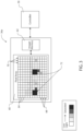
- FIG. 1 illustrates a vehicle 10 with a rearview system 14 .
- Rearview system 14 comprises one or more variable transmittance mirror 12 , a forward facing ambient light sensor 16 , a rearview imager 36 , and a controller 50 (not depicted in fig. 1 ).
- Variable transmittance mirror 12 may be any mirror operable to vary the degree to which light is transmitted.
- the transmittance of a mirror is the ratio of light reflected therefrom with respect to the light incident thereto. Accordingly, variable transmittance mirror 12 may be operable to dim. Further, variable transmittance mirror 12 may be operable to provide a user 22 a view of a rearward scene 28 .
- Variable transmittance mirror 12 may be located interior or exterior vehicle 10 .
- variable transmittance mirror 12 may be an interior rearview mirror 12a , a driver side rear-view mirror 12b , or a passenger side rear-view mirror 12c .
- Variable transmittance mirror 12 may be implemented using a variety of devices, such as those described in U.S. Pat. No. 3,680,951 entitled “PHOTOELECTRICALLY-CONTROLLED REAR-VIEW MIRROR” to Jordan et al. , and U.S. Pat. No. 4,443,057 entitled “AUTOMATIC REARVIEW MIRROR FOR AUTOMOTIVE VEHICLES” to Bauer et al. .
- Variable transmittance mirror 12 may be formed using liquid crystal cells as is described in U.S. Pat. No. 4,632,509 entitled “GLARE-SHIELDING TYPE REFLECTOR” to Ohmi et al. .
- variable transmittance mirror 12 may be implemented as an electrochromic cell which varies its transmittance in response to an applied control voltage, such as is described in U.S. Pat. No. 4,902,108 entitled “SINGLE-COMPARTMENT, SELF-ERASING, SOLUTION-PHASE ELECTROCHROMIC DEVICES, SOLUTIONS FOR USE THEREIN, AND USES THEREOF" to Byker . Though specific structures are disclosed for variable transmittance mirror 12 , many other electrochromic devices may be used to implement variable transmittance mirror 12 without departing from the spirit of the disclosure.
- Rearview imager 36 may be any device operable to capture image data, comprising a pixel array. Accordingly, rearview imager 36 is positioned and oriented such that it may capture image data corresponding to at least part of rearward scene 28 .
- rearview imager 36 may be located on a vehicle's 10 headliner, rear window, rear bumper, or trunk lid.
- the pixel array comprises a plurality of pixels in the form of light sensitive elements configured to measure light received through a lens or aperture. Each pixel of the pixel array may correspond to a photo-sensor, an array of photo sensors, or any grouping of sensors configured to capture light. Each of the photo-sensors may be operable to measure a value corresponding to a brightness or intensity of light.
- Rearview imager 36 may have a high dynamic range.
- rearview imager 36 may be in communication with an imager memory.
- the imager memory may be any device configured to store imager data.
- the imager memory may store pixel data and/or exposure data corresponding to each pixel of the pixel array.
- the imager memory may comprise various forms of memory, for example, random access memory (RAM), dynamic RAM (DRAM), synchronous DRAM (SDRAM), and other forms of memory configured to store digital information.
- RAM random access memory
- DRAM dynamic RAM
- SDRAM synchronous DRAM
- Each of the memory cells may correspond to an addressable memory location in the imager memory and have a capacity corresponding to the resolution of each pixel of the pixel array.
- Controller 50 may be any device operable to analyze image data from rearview imager 36 to determine the presence, intensity, or relative location of glare light 34 .
- controller 50 may be one or more processors, a multicore processor, or any combination of processors, circuits, and peripheral processing devices.
- controller 50 may comprise a memory operable to store a pixel analysis algorithm.
- controller 50 may be operable to adjust a reflectance, brightness, transmittance, or other display characteristic of one or more variable transmittance mirror 12 . Accordingly, controller 50 is communicatively connected to one or more variable transmittance mirror 12 and rearview imager 36 .
- rearview system 14 comprises a forward ambient light sensor 16 .
- Forward ambient light sensor 16 may be any device operable to sense the intensity of ambient light in the direction it is oriented. Accordingly, forward ambient light sensor 16 is disposed such that it may detect forward ambient light 32 and is communicatively connected to controller 50 .
- forward ambient light sensor 16 may be located on a windshield 30 , a headliner, or an interior rear-view mirror.
- rearview system 14 comprises a display.
- the display may be any digital screen, such as, a light emitting diode (LED) display, organic LED display, liquid crystal display (LCD), etc.
- the display may be communicatively connected to rearview imager 36 and operable to display a view of the exterior environment outside vehicle 10 .
- the display may be configured to display image data captured by rearview imager 36 to depict rearward scene 28 such that a user 22 may view rearward scene 28 in vehicle 10 without turning around.
- rearview system 14 may be used by user 22 to view rearward scene 28 via one or more variable transmittance mirror 12 . Further, while occupying vehicle 10 , user 22 typically looks forward through windshield 30 . Accordingly, the eyes of user 22 adjust to forward ambient light 32 . However, a relatively bright light source-often the headlights of a second vehicle-in rearward scene 28 may produce glare light 34 , which can reflect from a variable transmittance mirror 12 , temporarily impairing or distracting user 22 .
- controller 50 may adjust or limit the transmittance of one or more variable transmittance mirror 22 , based at least in part on the results of running the pixel analysis algorithm, where the pixel analysis algorithm analyzes image data from rearview imager 36 . Controller's 50 analysis of the image data may be achieved in a variety of ways.
- controller 50 may utilize image data from the frame to determine the presence of glare light 34 .
- the pixel analysis algorithm may be executed by controller 50 to analyze pixel data such that each pixel is given a scaled value representing the brightness or intensity of light to which it was exposed.
- the pixel may be given a scaled value from a minimum (e.g. 0) to a maximum value (e.g. 10,000).
- the scale may be of a linear relationship.
- the algorithm may identify a brightness of one or more pixels based on the scaled value. Pixels having scaled values above a glare threshold, or which are saturated (i.e. having maximum scaled values) may be used to identify glare light in rearward scene 28 .
- controller 50 may vary the transmittance of one or more variable transmittance mirror 12 , thereby limiting the reflection of glare light 34 by variable transmittance mirror 12 . Further, the level of transmittance may be directly related to a scaled value of one or more pixel based on a look up table or formula.
- the algorithm may be configured to further distinguish among levels of saturation in order to effectively extend the dynamic range of rearview imager 36 without requiring the dynamic range to be adjusted or skewed from the that which may typically be supplied to display 52 for viewing the rearward scene 26 , or a more expensive imager with increased dynamic range.
- the algorithm may monitor a number, distribution, concentration, spacing, arrangement, grouping, and/or proportions of the saturated pixels. For example, once a number of pixels exceeding a first saturated pixel threshold are identified as saturated, the algorithm may identify that glare light 34 is present in rearward scene 28 . In response, the algorithm may assign an increased scaled value (e.g. 11,000) to each of the saturated pixels. Additionally, if the number of saturated pixels exceed a second saturated pixel threshold, the algorithm may assign an increased scaled value (e.g. 12,000) to each of the pixels.
- an increased scaled value e.g. 12,000
- Such a weighting may be applied by the algorithm in response to detecting the number of saturated pixels as exceeding a third threshold, a fourth threshold, etc.; each of which may result in the algorithm reassigning respectively increased values (e.g. 13,000; 14,000; etc.).
- the algorithm may be configured to identify a number of contiguous, adjacent, or clustered pixels that are saturated. Based on the number of pixels contiguous, adjacent, or clustered saturated pixels, the algorithm may increase the scaled values of the contiguous, adjacent, or clustered saturated pixels by scalar values or multipliers.
- the algorithm may extend the dynamic range of rearview imager 36 by replacing saturated pixel values with an increased scaled value in accordance with a predetermined glaring scaled value. Accordingly, luminance values of the pixels that are saturated may be increased into an extended ranged (e.g. 11,000; 12,000; ... 19,000; 20,000).
- controller 50 may limit the transmittance of glare light 34 by controlling the transmittance of variable transmittance mirror 12 -thus darkening it. Accordingly, controller 50 may utilize a rearview imager 36 with a dynamic range suited to capturing light for display on display 52 , while detecting relative levels of glare light 34 , which may be simulated or monitored by controller 50 based on the extended range.
- controller 50 may be configured to compare a scaled value, extended scaled value, average scaled value, or average extended scaled value of one or more pixels with a light intensity level determined by forward ambient light sensor 16 . Accordingly, controller 50 may darken or limit the transmittance of variable transmittance mirror 12 , based at least in part on a ratio achieved by the light values from rearview imager 36 and forward ambient light sensor 16 . Therefore, controller 50 may ensure heightened scaled values are caused by glare light 34 opposed to bright ambient lighting conditions.
- Controller 50 may be configured to distinguish one or more region of rearward scene 26 .
- a region may correspond to one or more variable transmittance mirror 12 -such as an interior rearview mirror 12a, a driver side rear-view mirror 12b , or a passenger side rear-view mirror 12c -operable to reflect light from said region.
- a region may correspond to an area outside the field of view of a variable transmittance mirror 12 .
- controller 50 may independently control the transmittance of one or more variable transmittance mirror 12 with respect to when glare light 34 is not only detected, but likely present in variable transmittance mirror 12 .
- variable transmittance mirrors 12 independently varied to optimal transmittance levels, but in instances where rearview imager 36 may capture light not within the field of view of variable transmittance mirror 12 , the transmittance is not varied under a false determination of a need to reduce glare light 34 .
- the algorithm may be configured to detect a movement of glare light 34 .
- controller 50 may detect a movement of a pixel saturation or high scaled value within the pixel array.
- the algorithm may detect or infer a movement of glare light 34 as approaching vehicle 10 at a speed, based on a growth rate of the size of a saturated pixel group, a rate at which one or more pixels increase in detected light intensity, a rate at which the average scaled value of a group of pixels increases, or a reduction in time to pixel saturation.
- the imager memory may record an exposure time elapsed until saturation.
- controller 50 may anticipate a glare light's 34 future position and control the transmittance of one or more variable transmittance mirror 12 in response to the anticipation.
- controller 50 may delay adjusting the transmittance of one or more variable transmittance mirror 12 in anticipation of the second vehicle having moved outside of rearview imager's 36 field of view, but remaining within the variable transmittance mirror's 12 field of view for a duration thereafter. Further, in anticipation of the second vehicle overtaking on a specific side of vehicle 10 , controller 50 may selectively delay changing the transmittance of one or more variable transmittance mirror 12 specifically corresponding to said side.
- controller 50 may delay further adjusting the transmittance of a driver side rear-view mirror 12a for a duration. Accordingly, when a second vehicle providing glare light 34 passes vehicle 10 , the variable transmittance mirror 12 does not undergo an increase in transmittance prior to the second vehicle substantially completes its pass-through variable transmittance mirror's 12 field of view. This is of particular significance where variable transmittance mirror 12 has a field of view substantially comprising an area not present in the field of view of rearview imager 36 .
- the duration for which a change in transmittance is delayed by controller 50 in response to a detected movement of glare light 34 may be based at least in part on an inferred rate of speed or passing rate of the second vehicle.
- the detected rate of motion of glare light 34 may be analyzed with the use of a look up table, equation, or other method to determine the duration of the change in transmittance delay. Glare light 34 with faster detected movements may correlate to shorter delays and vice versa.
- the present disclosure has the technical advantage of providing a rearview system 14 wherein a dedicated glare sensor to detect light from rearward scene 28 is not required, therefore reducing the total number of devices needed when paired with a backup camera. Accordingly, the overall costs of the system are reduced. Additionally, the elimination of a sensor potentially reduces the number of obstructions in a user's 22 field of view. Further, in instances where the dedicated glare sensor is disposed on the variable transmittance mirror 12 or a housing thereof, the elimination of this sensor provides for a cleaner and more aesthetically appealing appearance.
- FIG. 2 is a schematic representation of a rearview system 14 .
- the rearview system comprises a variable transmittance mirror 12 , a rearview imager 36 , and a controller 50 .
- Variable transmittance mirror 12 comprises a variably transmissive element 42 and a reflective surface 44 .
- the transmittance is the ratio of light reaching the variably transmissive element 42 to the light passing through variably transmissive element 42 .
- variable transmittance mirror 12 is a mirror operable to dim.
- variable transmittance mirror 12 is operable to provide a view of at least part of a rearward scene.
- variable transmittance mirror 12 may be an interior rearview mirror, a driver side rear-view mirror, or a passenger side rear-view mirror.
- Rearview imager 36 may be any device operable to capture image data, comprising a pixel array. Accordingly, rearview imager 36 is disposed such that it has a field of view comprising at least part of the rearward scene.
- the pixel array comprises a plurality of pixels in the form of light sensitive elements configured to measure light received through a lens or aperture. Each pixel of the pixel array may correspond to a photo-sensor, an array of photo sensors, or any grouping of sensors configured to capture light. Each of the photo-sensors may be operable to measure a value corresponding to a brightness or intensity of light.
- Rearview imager 36 may have a high dynamic range.
- Controller 50 may be any device operable to analyze image data from rearview imager 36 to determine the presence, intensity, or relative location of glare light 34 .
- the controller may be one or more processors, a multicore processor, or any combination of processors, circuits, and peripheral processing devices.
- the controller may comprise a memory operable to store a pixel analysis algorithm and image data relating to at least one frame taken by rearview imager 36 .
- the controller may be operable to adjust a reflectance, brightness, transmittance, or other display characteristic of one or more variable transmittance mirror 12 . Accordingly, the controller is communicatively connected to variable transmittance mirror 12 and rearview imager 36 .
- rearview system 14 may further comprise a forward ambient light sensor 16 .
- Forward ambient light sensor 16 may be any device operable to sense the intensity of ambient light. Accordingly, forward ambient light sensor 16 is disposed such that it may detect ambient light 32 in generally opposite the direction of the rearward scene and is communicatively connected to controller 50 .
- rearview system 14 may further comprise a display 52 .
- Display 52 may be any digital screen, such as, a light emitting diode (LED) display, organic LED display, liquid crystal display (LCD), etc.
- Display 52 may be communicatively connected to rearview imager 36 and operable to display a view of the exterior environment outside vehicle 10 .
- display 52 may be configured to display image data captured by rearview imager 36 to depict rearward scene 28 such that a user may view the rearward scene.
- display 52 may be disposed within variable transmittance mirror 12 such that variable transmittance mirror 12 is operable to switch between an electronic display mode and a traditional dimmable mirror mode, according to methods well known in the art.
- rearview system 14 may be used by a user to view the rearward scene via variable transmittance mirror 12 .
- a user's eyes are looking forward and accordingly adjust to forward ambient light 32 levels.
- a relatively bright light source-often the headlights of a vehicle-in the rearward scene may produce glare light 34 , which can reflect off of reflective surface 44 and temporarily impair or distract the user.
- controller 50 may adjust or limit the transmittance of variable transmissive element 42 , based at least in part on the results of running the pixel analysis algorithm.
- the pixel analysis algorithm analyzes image data from rearview imager 36 .
- the algorithm's analysis of the image data may be achieved in a variety of ways.
- the algorithm may utilize image data from the frame to determine the presence of glare light 34 .
- the algorithm may analyze pixel data such that each pixel is given a scaled value reflecting the brightness or intensity of light to which it was exposed.
- the pixel may be given a scaled value from a minimum (e.g. 0) to a maximum value (e.g. 10,000).
- the scale may be of a linear relationship.
- the controller may identify a brightness of one or more pixels based on the scaled value. Pixels having scaled values above a glare threshold, or which are saturated (i.e. having maximum scaled values), may be used to identify glare light in the rearward scene.
- controller 50 may vary the transmittance of variable transmittance mirror 12 , thereby limiting the reflection of glare light 34 by variable transmittance mirror 12 . Further, the level of transmittance may be directly related to a scaled value of one or more pixel based on a look up table or formula.
- the algorithm may be configured to further distinguish among levels of saturation in order to effectively extend the dynamic range of rearview imager 36 without requiring the dynamic range to be adjusted or skewed from the that which may typically be supplied to display 52 for viewing the rearward scene.
- the algorithm may monitor a number, distribution, concentration, spacing, arrangement, grouping, and/or proportions of the saturated pixels. For example, once a number of pixels exceeding a first saturated pixel threshold are identified as saturated, the algorithm, may identify that glare light 34 is present in the rearward scene. In response, the algorithm may assign an increased scaled value (e.g. 11,000) to each of the saturated pixels. Additionally, if the number of saturated pixels exceed a second saturated pixel threshold, the algorithm may assign an increased scaled value (e.g. 12,000) to each of the pixels.
- an increased scaled value e.g. 12,000
- Such a weighting may be applied by the algorithm in response to detecting the number of saturated pixels as exceeding a third threshold, a fourth threshold, etc.; each of which may result in the controller reassigning respectively increased values (e.g. 13,000; 14,000; etc.).
- the algorithm may be configured to identify a number of contiguous, adjacent, or clustered pixels that are saturated. Based on the number of contiguous, adjacent, or clustered saturated pixels, the algorithm may increase the scaled values of the pixels contiguous, adjacent, or clustered saturated pixels by scalar values or multipliers.
- the algorithm may extend the dynamic range of rearview imager 36 by simply replacing any saturated pixel value with an increased scaled value in accordance with a predetermined glaring scaled value. Accordingly, as illustrated by the preceding examples, luminance values of the pixels that are saturated may be increased into an extended ranged (e.g. 11,000; 12,000; ... 19,000; 20,000).
- an extended ranged e.g. 11,000; 12,000; ... 19,000; 20,000.
- controller 50 may limit the transmittance of glare light 34 by adjusting the transmittance of variable transmittance mirror 12 -thus darkening it. Accordingly, controller 50 may utilize a rearview imager 36 with a dynamic range suited to capturing light for display on display 52 and/or with a lower cost, while detecting relative levels of glare light 34 beyond its normal range.
- the algorithm may be configured to compare a scaled value, extended scaled value, average scaled value, or average extended scaled value of one or more pixels to a light intensity level determined by forward ambient light sensor 16 . Accordingly, controller 50 may darken or limit the transmittance of variable transmittance mirror 12 , based at least in part on a ratio achieved by the light level values from rearview imager 36 and forward ambient light sensor 16 . Therefore, controller 50 may ensure heightened scaled values are caused by glare light 34 opposed to ambient lighting conditions.
- controller 50 may be configured to distinguish one or more region of the rearward scene.
- a region may correspond to the field of view of variable transmittance mirror 12 .
- a region may correspond to an area outside the field of view of variable transmittance mirror 12 . Accordingly, controller 50 may adjust the transmittance of variable transmittance mirror 12 with respect to when glare light 34 is not only detected, but likely present in variable transmittance mirror 12 . Therefore, in instances where rearview imager 36 may capture light not within the field of view of variable transmittance mirror 12 , the transmittance is not varied under a false determination of a need to reduce glare light 34 .
- the algorithm may be configured to detect a movement of glare light 34 .
- the algorithm may detect a movement of a pixel saturation or high scaled value within the pixel array.
- the algorithm may detect or infer a movement of glare light 34 as approaching vehicle 10 at a speed, based on a growth rate of the size of a saturated pixel group, a rate at which one or more pixels increase in detected light intensity, a rate at which the average scaled value of a group of pixels increases, or a reduction in time to pixel saturation.
- the memory may record an exposure time elapsed until saturation.
- the algorithm may anticipate a glare light's 34 future position and control the transmittance of one or more variable transmittance mirror 12 in response to the anticipation.
- the algorithm may identify or infer that a second vehicle is the first vehicle, and optionally identify whether the second vehicle will likely move into a region outside rearview imager's 36 field of view, but within variable transmittance mirror's 12 field of view. Accordingly, the controller may delay adjusting the transmittance of one or more variable transmittance mirror 12 in anticipation of the second vehicle having moved outside of rearview imager's 36 field of view but remaining within the variable transmittance mirror's 12 field of view for a duration thereafter.
- variable transmittance mirror 12 may delay further adjusting the transmittance of a variable transmittance mirror 12 on a driver side of a vehicle for a duration. Therefore, when a vehicle providing glare light 34 passes, the variable transmittance mirror 12 does not undergo an increase in transmittance prior to the vehicle substantially completing its pass-through variable transmittance mirror's 12 field of view. This is of particular significance where variable transmittance mirror 12 has a field of view substantially comprising an area not present in the field of view of rearview imager 36 .
- the duration for which a change in transmittance is delayed by controller 50 in response to a detected movement of glare light 34 may be based at least in part on an inferred rate of speed or passing rate of the second vehicle.
- the detected rate of motion of glare light 34 may be analyzed by the algorithm with the use of a look up table, equation, or other method to determine the duration of the change in transmittance delay. Glare light 34 with faster detected movements may correlate to shorter delays and vice versa.
- the present disclosure has the technical advantage of providing a rearview system 14 wherein a dedicated glare sensor to detect light from rearward scene 28 is not required, therefore reducing the total number of devices needed when paired with a backup camera.
- FIG. 3 is a schematic diagram of a rearview system.
- Rearview system comprises a rearview imager 36 and a controller 50 .
- Rearview imager 36 comprises a pixel array 60 .
- Pixel array 60 comprises a plurality of pixels 64 in the form of light sensitive elements configured to measure light that may be received though a lens or aperture.
- the pixel array 60 may be arranged in rows 68 and columns 70 .
- Each pixel 64 of the pixel array 60 may correspond to a photo-sensor, an array of photo sensors, or any grouping of sensors configured to capture light.
- Each of the photo-sensors may be operable to measure a pixel value corresponding to a brightness or intensity of light.
- rearview imager 36 may be in communication with an imager memory 62 .
- the imager memory may be configured to store imager data.
- the imager memory may store pixel data and/or exposure data corresponding to each pixel of the pixel array.
- the imager memory may comprise various forms of memory, for example, random access memory (RAM), dynamic RAM (DRAM), synchronous DRAM (SDRAM), and other forms of memory configured to store digital information.
- RAM random access memory
- DRAM dynamic RAM
- SDRAM synchronous DRAM
- Each of the memory cells may correspond to an addressable memory location in the imager memory and have a capacity corresponding to the resolution of each pixel of the pixel array.
- controller 50 may be any device operable to analyze image data from rearview imager 36 to determine the presence, intensity, or relative location of glare light.
- controller 50 may be one or more processors, a multicore processor, or any combination of processors, circuits, and peripheral processing devices.
- controller 50 may comprise a memory operable to store a pixel analysis algorithm.
- controller 50 may be operable to adjust a reflectance, brightness, transmittance, or other display characteristic of one or more variable transmittance mirror. Controller 50 may also be operable to receive and process ambient light data from an ambient light sensor.
- glare light may be sensed and identified by a rearview system to adjust one or more variable transmittance mirror, based at least in part on the results of running the pixel analysis algorithm, according to the following method.
- a frame is exposed by rearview imager 36 to generate image data.
- the presence of glare light is determined by the algorithm utilizing the image data from the frame. The presence of glare light may be determined by the algorithm in accordance with a variety of methods.
- controller 50 may vary the transmittance of the variable transmittance mirror, thereby limiting the possible reflection of glare light by the variable transmittance mirror. Controller 50 may vary the transmittance in a variety of manners responsive to the method the algorithm uses to determine the presence of glare light.
- the algorithm operates by assigning each pixel a scaled value reflecting the brightness or intensity of light to which it was exposed.
- the pixel may be given a scaled value from a minimum (e.g. 0) to a maximum value (e.g. 10,000).
- the scale may be of a linear relationship.
- the algorithm may next identify an intensity of glare light for one or more pixels based on the scaled value. Pixels 64 having scaled values above a glare threshold or which are saturated (i.e. having maximum scaled values) may be used to identify glare light in the rearward scene.
- the transmittance of the variable transmittance mirror may be varied by controller 50 , thereby limiting the possible reflection of glare light by the variable transmittance mirror.
- the level of transmittance may be directly related to a scaled value of one or more pixel based on a look up table or formula.
- levels of saturation are distinguished.
- the algorithm may distinguish among levels of saturation in order to effectively extend the dynamic range of rearview imager 36 without requiring the dynamic range to be adjusted or skewed from the that which may typically be supplied to a display for viewing the rearward scene or requiring a high dynamic range rearview imager 36 of greater cost.
- the algorithm may monitor a number, distribution, concentration, spacing, arrangement, grouping, and/or proportions of saturated pixels 72 . For example, once a number of pixels 64 exceeding a first saturated pixel threshold are identified as saturated, the algorithm, may identify that glare light is present in the rearward scene. In response, the algorithm may assign an increased scaled value (e.g. 11,000) to each of the saturated pixels 72 . Additionally, if the number of saturated pixels 72 exceed a second saturated pixel threshold, the algorithm may assign an increased scaled value (e.g. 12,000) to each of the saturated pixels 72 .
- an increased scaled value e.g. 11,000
- Such a weighting may be applied by the algorithm in response to detecting the number of saturated pixels 72 as exceeding a third threshold, a fourth threshold, etc.; each of which may result in the algorithm reassigning respectively increased values (e.g. 13,000; 14,000; etc.).
- the algorithm may be configured to identify a number of contiguous, adjacent, or clustered saturated pixels 72 . Based on the number of contiguous, adjacent, or clustered saturated pixels 72 , the algorithm may increase the scaled values of the contiguous, adjacent, or clustered saturated pixels 72 by scalar values or multipliers.
- the algorithm may extend the dynamic range of rearview imager 36 by simply replacing any saturated pixel value with an increased scaled value in accordance with a predetermined glaring scaled value. Accordingly, as illustrated by the preceding examples, scaled values of the pixels that are saturated may be increased into an extended ranged (e.g. 11,000; 12,000; ... 19,000; 20,000).
- an extended ranged e.g. 11,000; 12,000; ... 19,000; 20,000.
- controller 50 may limit a reflectance of glare light by the variable transmittance mirror by adjusting its transmittance-thus darkening it. Therefore, controller 50 may utilize a rearview imager 36 with a dynamic range suited to capturing light for display on a display and/or with a lower cost, while detecting relative levels of glare light 34 beyond its normal range.
- a scaled value, extended scaled value, average scaled value, or average extended scaled value of one or more pixels 64 may be compared by the algorithm with a light intensity level determined by an ambient light sensor. Accordingly, the transmittance of the variable transmittance mirror may be limited by controller 50 , based at least in part on a ratio achieved by the light level values from rearview imager 36 and the ambient light sensor. Therefore, controller 50 may ensure heightened scaled values are due to glare light, opposed to ambient lighting conditions
- one or more region of the rearward scene may be distinguished by controller 50 .
- a region may correspond to the field of view of the variable transmittance mirror.
- a region may also correspond to an area outside the field of view of variable transmittance mirror. Accordingly, the transmittance of the variable transmittance mirror may be adjusted by controller 50 with respect to when glare light is not only detected, but likely present in the variable transmittance mirror. Therefore, instances where rearview imager 36 may capture light not within the field of view of the variable transmittance mirror, the transmittance is not varied under a false determination of a need to reduce glare light.
- movement of glare light may be detected by the algorithm.
- the movement of glare light may be detected by a variety of manners.
- the algorithm may detect a movement of a pixel saturation or high scaled value within the pixel array 60 .
- the algorithm may detect or infer a movement of glare light as approaching at a speed, based on a growth rate of the size of a saturated pixel 72 group, a rate at which one or more pixels 64 increase in detected light intensity, a rate at which the average scaled value of a group of pixels 64 increases, or a reduction in time to pixel 64 saturation, over a successive series of frame.
- detection of a reduction in time to pixel saturation, during exposure of a single frame, for one or more pixels 64 may occur by recording an exposure time elapsed until saturation by imager memory 62 .
- the algorithm may anticipate a glare light's future position and control the transmittance of one or more variable transmittance mirror in response to the anticipation. For example, based on a movement of glare light, the algorithm may identify or infer that a second vehicle is passing a first vehicle and optionally identify whether the second vehicle will likely move into a region outside rearview imager's 36 field of view, but within the variable transmittance mirror's field of view.
- the transmittance of the variable transmittance mirror may be varied by controller 50 where delays adjusting the transmittance of one or more variable transmittance mirror 12 in anticipation of the second vehicle having moved outside of rearview imager's 36 field of view but remaining within the variable transmittance mirror's field of view for a duration thereafter. For example, if glare light is detected moving in a leftward direction, once glare light 34 has moved beyond the field of view of rearview imager 36 , controller 50 may delay further adjusting the transmittance of a variable transmittance mirror on a driver side of the first vehicle for a duration.
- variable transmittance mirror when a vehicle providing glare light passes, the variable transmittance mirror does not undergo an increase in transmittance prior to the vehicle substantially completing its pass-through the variable transmittance mirror's field of view. This is of particular significance where the variable transmittance mirror has a field of view substantially comprising an area not present in the field of view of rearview imager 36 .
- the duration for which a change in transmittance is delayed by controller 50 in response to a detected movement of glare light 34 may be based at least in part on an inferred rate of speed or passing rate of the second vehicle.
- the detected rate of motion of glare light may be analyzed by the algorithm with the use of a look up table, equation, or other method to determine the duration of the change in transmittance delay. Glare light with faster detected movements may correlate to shorter delays and vice versa.
- the present disclosure has the technical advantage of providing a rearview system wherein a dedicated glare sensor to detect light from rearward scene is not required, therefore reducing the total number of devices needed when paired with a backup camera.
- Figure 4 is an exemplary embodiment of image data 80 captured by a rearview imager disposed on a first vehicle.
- Image data 80 corresponds to a rearview scene 26 as captured by the rearview imager.
- Rearview scene 26 contains a trailing vehicle 82 .
- Trailing vehicle 82 is shown in a first position 82a and a second position 82b . As shown, trailing vehicle 82 is represented as being closer to the first vehicle in second position 82b relative to the first position 82a .
- Trailing vehicle 82 may have headlights 72 which may be a source of glare light 34 .
- Image data 80 may be analyzed by a pixel analysis algorithm stored in a controller communicatively linked to the rearview imager.
- the algorithm may be operable to identify glare light 34 based on image data 80 .
- the algorithm may be operable to differentiate between and identify glare light 34 in one or more region of interest 84 .
- the region of interest 84 may correspond to a field of view of one or more variable transmittance mirror.
- the controller may adjust the transmittance of a variable transmittance mirror based on the detection of glare light specifically within the variable transmittance mirror's field of view, opposed to simply in rearward scene.
- the controller may be configured to selectively process the one or more regions of interest 84 based on a focal length, field of view, mounting position, and/or various properties of the rearview imager. Accordingly, selective processing reduces data analysis times by limiting analysis to relevant areas of the rearview imager's field of view
- the algorithm may vary a location 86 of one or more of the regions of interest 84 based on input signals that may indicate a steering direction or navigation direction of the first vehicle.
- the controller may be in communication with a steering angle sensor, inertial sensor, gyroscope, navigation system, and/or various directional detection devices of the fist vehicle. Accordingly, the algorithm may move the region of interest 84 in anticipation of changing relative positions of the first and trailing vehicles.
- the algorithm may be configured to selectively process one or more objects (e.g. a vanishing point, lane line, horizon, etc.) and dynamically position the region of interest 84 to assist in the identification of glare light 34 .
- the controller may further be operable to detect a location or relative intensity of glare light 34 to control the transmittance of a variable transmittance mirror, based on an anticipated change in a field of view of the variable transmittance mirror.
- the algorithm may be configured to detect a movement 88 of the glare light 34 from a first position 82a to a second position 82b .
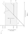
- FIG. 5 illustrates an exemplary dimming routine plot 100 for a variable transmittance mirror.
- Dimming routine plot 100 plots scaled values as a function of actual light intensity. Scaled values are numbers assigned to a pixel to representing the brightness or intensity of light to which the pixel is exposed.
- a rearview imager may be operable to capture image data corresponding to a rearward scene via a pixel array.
- the image data may be analyzed by an algorithm run by a controller.
- the algorithm may measure light of the pixels by determining and/or adjusting a scaled value for one or more pixel. As shown, the intensity of the light may be determined by the controller within a range of 0 to 20,000.
- the rearview imager may have a dynamic range 102 with an upper limit lower than 20,000. Accordingly, the controller may supplement the range with an extended dynamic range 104 calculated by the algorithm.
- the saturation of a pixel may occur at a saturation threshold 106 corresponding to a scaled value of 10,000. Accordingly, when exposed to light having a greater intensity than the saturation threshold 106 , pixels will be saturated and data beyond the saturation threshold as to the intensity of the light lost.
- the algorithm may be configured to further distinguish among levels of saturation in order to effectively extend the dynamic range of rearview imager 36 without requiring the dynamic range to be adjusted or skewed.
- the algorithm may assign an increased scaled value (e.g. 11,000) to each of the saturated pixels. Additionally, if the number of saturated pixels exceed a second saturated pixel threshold, the algorithm may assign an increased scaled value (e.g. 12,000) to each of the pixels. Such a weighting may be applied by the algorithm in response to detecting the number of saturated pixels as exceeding a third threshold, a fourth threshold, etc.; each of which may result in the controller reassigning respectively increased values (e.g. 13,000; 14,000; etc.). In another example, the algorithm may be configured to identify a number of contiguous, adjacent, or clustered pixels that are saturated.
- the algorithm may increase the scaled values of the pixels contiguous, adjacent, or clustered saturated pixels by scalar values or multipliers.
- the algorithm may extend the dynamic range of rearview imager by simply replacing any saturated pixel value with an increased scaled value in accordance with a predetermined glaring scaled value. Accordingly, as illustrated by the preceding examples, luminance values of the pixels that are saturated may be increased into an extended ranged (e.g. 11,000; 12,000; ... 19,000; 20,000).
- the controller may limit a variable transmittance mirror's transmittance of glare light by adjusting the transmittance of the variable transmittance mirror-thus darkening it. Further, the degree to which the transmittance may be adjusted (i.e. the dimming level) may be directly related to one or more scaled value. Accordingly, the controller may utilize a rearview imager with a dynamic range suited to capturing light for display on display and/or with a lower cost, while detecting relative levels of glare light beyond its normal range.
- the controller may adjust the transmittance of a variable transmittance mirror when the scaled value is in a range of 8,000 (lower dimming threshold 108 ) to 18,000 (upper dimming threshold 110 ) . Further, the dimming level of the variable transmittance mirror may increase with increasing scaled values up to and beyond the saturation threshold 106 .
- the term "and/or,” when used in a list of two or more items, means that any one of the listed items can be employed by itself, or any combination of the two or more of the listed items can be employed.
- the composition can contain A alone; B alone; C alone; A and B in combination; A and C in combination; A and C in combination; B and C in combination; or A, B, and C in combination.
Description
- This application claims priority under 35 U.S.C. § 119(e) to
U.S. provisional Application No. 62/771,312 filed on November 26, 2018 - The present invention generally relates to light sensors and, more particularly, to light sensors used for rearview assemblies of vehicles.
- Variable transmittance mirrors have been well known for many years. Systems for variable transmittance rearview mirrors rely on a forward facing ambient light sensor and a rearward facing ambient light sensor positioned near the mirror-often referred to as a glare sensor. A controller accordingly determines a difference in intensity levels between the two ambient light sensors in order to estimate when a glaring light is present and accordingly vary the transmittance of the mirrors.
-
US 2005/007645 A1 describes that the electrochromic mirror may be used in a vehicle rearview mirror assembly having a light source positioned behind the electrochromic mirror for selectively projecting light through the mirror. -
US 6 356 376 B1 describes an electrochromic mirror for use in a vehicle rearview mirror assembly having a light source positioned behind the electrochromic mirror for selectively projecting light through the mirror. - However, in systems comprising more than one variable transmittance rearview mirror, the system operates to vary the transmittance of all the mirrors together equally based on the single difference between the two ambient light sensors. Further, in some instances, glaring light may impact a user via each mirror by varying degrees as a result of the glaring light source's position. Thus, varying the transmittance of all mirrors equally may result in un-optimal degrees of transmittance for one or more mirrors.
- Additionally, most vehicles are equipped with a back-up camera-which are well known in the art. Unlike the ambient light sensors of the variable transmittance mirror systems, which merely detect a light intensity, these cameras capture data via a pixel array to produce an image and often have lower dynamic ranges. Therefore, vehicles are equipped with yet an additional device.
- Accordingly, there is a need for an improved variable transmittance mirror system whereby the total number of devices needed when paired with a back-up camera is reduced. Moreover, there is likewise a need for an improved variable transmittance mirror system whereby mirrors are varied in improved degrees with respect to glaring light sources of variable positions.
- In accordance with the present disclosure, the disadvantages and problems associated with variable transmittance mirror systems in the past have been substantially reduced or eliminated.
- The present invention is defined by the claims.
- In accordance with one embodiment of the present disclosure, a system comprising a first imager, a first variable transmittance mirror, and a controller is disclosed. The first imager comprises a pixel array. Further, the first imager is configured to capture image data. The first variable transmittance mirror has a first level of transmittance. Finally, the controller is configured to assign a first light intensity value to one or more pixels and change the first level of transmittance to a second level of transmittance based at least in part on the detected first light intensity.
- The advantages of certain embodiments of the present disclosure include of providing a rearview system wherein a dedicated glare sensor to detect light from rearward scene is not required, therefore reducing the total number of devices needed when paired with a backup camera. Accordingly, the overall costs of the system are reduced. Additionally, the elimination of a sensor potentially reduces the number of obstructions in a user's flied of view. Further, in instances where the dedicated glare sensor would otherwise be disposed on a variable transmittance mirror or a housing thereof, the elimination of this sensor provides for a cleaner and more aesthetically appealing appearance.
- These and other aspects, objects, and features of the present disclosure will be understood and appreciated by those skilled in the art upon studying the following specification, claims, and appended drawings.
- In the drawings:
-
Fig. 1 : Vehicle with rearview system. -
Fig. 2 : Rearview system schematic. -
Fig. 3 : Schematic diagram of aspects of a rearview system. -
Fig. 4 : Exemplary embodiment of image data captured by a rearview imager. -
Fig. 5 : Exemplary demining routine plot for a variable transmittance mirror. - For the purposes of description herein, it is to be understood that the specific devices and processes illustrated in the attached drawings and described in this disclosure are simply exemplary embodiments of the inventive concepts defined in the appended claims. Hence, specific dimensions and other physical characteristics relating the embodiments disclosed herein are not to be considered as limiting, unless the claims expressly state otherwise.
-
Figure 1 illustrates avehicle 10 with arearview system 14.Rearview system 14 comprises one or morevariable transmittance mirror 12, a forward facingambient light sensor 16, arearview imager 36, and a controller 50 (not depicted infig. 1 ). -
Variable transmittance mirror 12 may be any mirror operable to vary the degree to which light is transmitted. The transmittance of a mirror is the ratio of light reflected therefrom with respect to the light incident thereto. Accordingly,variable transmittance mirror 12 may be operable to dim. Further,variable transmittance mirror 12 may be operable to provide a user 22 a view of arearward scene 28.Variable transmittance mirror 12 may be located interior orexterior vehicle 10. For example,variable transmittance mirror 12 may be an interior rearview mirror 12a, a driver side rear-view mirror 12b, or a passenger side rear-view mirror 12c. -
Variable transmittance mirror 12 may be implemented using a variety of devices, such as those described inU.S. Pat. No. 3,680,951 entitled "PHOTOELECTRICALLY-CONTROLLED REAR-VIEW MIRROR" to Jordan et al. , andU.S. Pat. No. 4,443,057 entitled "AUTOMATIC REARVIEW MIRROR FOR AUTOMOTIVE VEHICLES" to Bauer et al. .Variable transmittance mirror 12 may be formed using liquid crystal cells as is described inU.S. Pat. No. 4,632,509 entitled "GLARE-SHIELDING TYPE REFLECTOR" to Ohmi et al. . In an exemplary embodiment,variable transmittance mirror 12 may be implemented as an electrochromic cell which varies its transmittance in response to an applied control voltage, such as is described inU.S. Pat. No. 4,902,108 entitled "SINGLE-COMPARTMENT, SELF-ERASING, SOLUTION-PHASE ELECTROCHROMIC DEVICES, SOLUTIONS FOR USE THEREIN, AND USES THEREOF" to Byker . Though specific structures are disclosed forvariable transmittance mirror 12, many other electrochromic devices may be used to implementvariable transmittance mirror 12 without departing from the spirit of the disclosure. -
Rearview imager 36 may be any device operable to capture image data, comprising a pixel array. Accordingly,rearview imager 36 is positioned and oriented such that it may capture image data corresponding to at least part ofrearward scene 28. For example,rearview imager 36 may be located on a vehicle's 10 headliner, rear window, rear bumper, or trunk lid. The pixel array comprises a plurality of pixels in the form of light sensitive elements configured to measure light received through a lens or aperture. Each pixel of the pixel array may correspond to a photo-sensor, an array of photo sensors, or any grouping of sensors configured to capture light. Each of the photo-sensors may be operable to measure a value corresponding to a brightness or intensity of light.Rearview imager 36 may have a high dynamic range. - In some embodiments,
rearview imager 36 may be in communication with an imager memory. The imager memory may be any device configured to store imager data. For example, the imager memory may store pixel data and/or exposure data corresponding to each pixel of the pixel array. The imager memory may comprise various forms of memory, for example, random access memory (RAM), dynamic RAM (DRAM), synchronous DRAM (SDRAM), and other forms of memory configured to store digital information. Each of the memory cells may correspond to an addressable memory location in the imager memory and have a capacity corresponding to the resolution of each pixel of the pixel array. - Examples of
rearview imagers 36 configured to operate as high dynamic range image sensors are disclosed inU.S. Pat. No. 8,289,430 entitled "HIGH DYNAMIC RANGE IMAGING DEVICE," filed Dec. 6, 2007, by Jon H. Bechtel et al. ;U.S. Pat. No. 8,305,471 entitled "HIGH DYNAMIC RANGE IMAGING DEVICE," filed Apr. 25, 2008, by Jon H. Bechtel et al. ;U.S. Pat. No. 8,378,284 entitled "IMAGING DEVICE," filed Jan. 28, 2009, by Daniel Van Blerkom et al. ;U.S. Pat. No. 8,144,223 entitled "IMAGING DEVICE," filed Jan. 28, 2009, by Daniel Van Blerkom et al. ;U.S. Pat. No. 8,629,927 entitled "IMAGING DEVICE," filed Apr. 9, 2008 by Jon H. Bechtel et al. ;U.S. Pat. No. 8,587,706 entitled "IMAGING DEVICE," filed Jun. 11, 2008, by Jon H. Bechtel ; andU.S. Pat. No. 9,041,838 entitled "HIGH DYNAMIC RANGE IMAGER SYSTEM," filed Feb. 14, 2013, by Jon H. Bechtel -
Controller 50 may be any device operable to analyze image data fromrearview imager 36 to determine the presence, intensity, or relative location ofglare light 34. For example,controller 50 may be one or more processors, a multicore processor, or any combination of processors, circuits, and peripheral processing devices. Additionally,controller 50 may comprise a memory operable to store a pixel analysis algorithm. Further,controller 50 may be operable to adjust a reflectance, brightness, transmittance, or other display characteristic of one or morevariable transmittance mirror 12. Accordingly,controller 50 is communicatively connected to one or morevariable transmittance mirror 12 andrearview imager 36. - In some embodiments,
rearview system 14 comprises a forward ambientlight sensor 16. Forward ambientlight sensor 16 may be any device operable to sense the intensity of ambient light in the direction it is oriented. Accordingly, forward ambientlight sensor 16 is disposed such that it may detect forwardambient light 32 and is communicatively connected tocontroller 50. For example, forward ambientlight sensor 16 may be located on awindshield 30, a headliner, or an interior rear-view mirror. - In some embodiments,
rearview system 14 comprises a display. The display may be any digital screen, such as, a light emitting diode (LED) display, organic LED display, liquid crystal display (LCD), etc. The display may be communicatively connected torearview imager 36 and operable to display a view of the exterior environment outsidevehicle 10. For example, the display may be configured to display image data captured byrearview imager 36 to depictrearward scene 28 such that auser 22 may view rearwardscene 28 invehicle 10 without turning around. - In operation,
rearview system 14 may be used byuser 22 to view rearwardscene 28 via one or morevariable transmittance mirror 12. Further, while occupyingvehicle 10,user 22 typically looks forward throughwindshield 30. Accordingly, the eyes ofuser 22 adjust to forwardambient light 32. However, a relatively bright light source-often the headlights of a second vehicle-inrearward scene 28 may produceglare light 34, which can reflect from avariable transmittance mirror 12, temporarily impairing or distractinguser 22. Accordingly, to reduce the impact ofglare light 34 onuser 22,controller 50 may adjust or limit the transmittance of one or morevariable transmittance mirror 22, based at least in part on the results of running the pixel analysis algorithm, where the pixel analysis algorithm analyzes image data fromrearview imager 36. Controller's 50 analysis of the image data may be achieved in a variety of ways. - Upon completion of an exposure of a frame captured by
rearview imager 36,controller 50 may utilize image data from the frame to determine the presence ofglare light 34. The pixel analysis algorithm may be executed bycontroller 50 to analyze pixel data such that each pixel is given a scaled value representing the brightness or intensity of light to which it was exposed. For example, the pixel may be given a scaled value from a minimum (e.g. 0) to a maximum value (e.g. 10,000). In some embodiments, the scale may be of a linear relationship. Accordingly, the algorithm may identify a brightness of one or more pixels based on the scaled value. Pixels having scaled values above a glare threshold, or which are saturated (i.e. having maximum scaled values) may be used to identify glare light inrearward scene 28. - In response to the algorithm identifying one or more pixels having a scaled value above the glare threshold,
controller 50 may vary the transmittance of one or morevariable transmittance mirror 12, thereby limiting the reflection ofglare light 34 byvariable transmittance mirror 12. Further, the level of transmittance may be directly related to a scaled value of one or more pixel based on a look up table or formula. - In some embodiments, the algorithm may be configured to further distinguish among levels of saturation in order to effectively extend the dynamic range of
rearview imager 36 without requiring the dynamic range to be adjusted or skewed from the that which may typically be supplied to display 52 for viewing the rearward scene 26, or a more expensive imager with increased dynamic range. - When saturated pixels are present, the algorithm may monitor a number, distribution, concentration, spacing, arrangement, grouping, and/or proportions of the saturated pixels. For example, once a number of pixels exceeding a first saturated pixel threshold are identified as saturated, the algorithm may identify that
glare light 34 is present inrearward scene 28. In response, the algorithm may assign an increased scaled value (e.g. 11,000) to each of the saturated pixels. Additionally, if the number of saturated pixels exceed a second saturated pixel threshold, the algorithm may assign an increased scaled value (e.g. 12,000) to each of the pixels. Such a weighting may be applied by the algorithm in response to detecting the number of saturated pixels as exceeding a third threshold, a fourth threshold, etc.; each of which may result in the algorithm reassigning respectively increased values (e.g. 13,000; 14,000; etc.). In another example, the algorithm may be configured to identify a number of contiguous, adjacent, or clustered pixels that are saturated. Based on the number of pixels contiguous, adjacent, or clustered saturated pixels, the algorithm may increase the scaled values of the contiguous, adjacent, or clustered saturated pixels by scalar values or multipliers. In another example, the algorithm may extend the dynamic range ofrearview imager 36 by replacing saturated pixel values with an increased scaled value in accordance with a predetermined glaring scaled value. Accordingly, luminance values of the pixels that are saturated may be increased into an extended ranged (e.g. 11,000; 12,000; ... 19,000; 20,000). - Based on the scaled values associated with the extended value range of one or more pixels, or an average thereof,
controller 50 may limit the transmittance ofglare light 34 by controlling the transmittance of variable transmittance mirror 12-thus darkening it. Accordingly,controller 50 may utilize arearview imager 36 with a dynamic range suited to capturing light for display ondisplay 52, while detecting relative levels ofglare light 34, which may be simulated or monitored bycontroller 50 based on the extended range. - In some embodiments,
controller 50 may be configured to compare a scaled value, extended scaled value, average scaled value, or average extended scaled value of one or more pixels with a light intensity level determined by forward ambientlight sensor 16. Accordingly,controller 50 may darken or limit the transmittance ofvariable transmittance mirror 12, based at least in part on a ratio achieved by the light values fromrearview imager 36 and forward ambientlight sensor 16. Therefore,controller 50 may ensure heightened scaled values are caused byglare light 34 opposed to bright ambient lighting conditions. -
Controller 50 may be configured to distinguish one or more region of rearward scene 26. A region may correspond to one or more variable transmittance mirror 12-such as an interior rearview mirror 12a, a driver side rear-view mirror 12b, or a passenger side rear-view mirror 12c-operable to reflect light from said region. Alternatively, a region may correspond to an area outside the field of view of avariable transmittance mirror 12. Accordingly,controller 50 may independently control the transmittance of one or morevariable transmittance mirror 12 with respect to whenglare light 34 is not only detected, but likely present invariable transmittance mirror 12. Therefore, not only are individual variable transmittance mirrors 12 independently varied to optimal transmittance levels, but in instances whererearview imager 36 may capture light not within the field of view ofvariable transmittance mirror 12, the transmittance is not varied under a false determination of a need to reduceglare light 34. - In some embodiments, the algorithm may be configured to detect a movement of
glare light 34. For example,controller 50 may detect a movement of a pixel saturation or high scaled value within the pixel array. Likewise, the algorithm may detect or infer a movement of glare light 34 as approachingvehicle 10 at a speed, based on a growth rate of the size of a saturated pixel group, a rate at which one or more pixels increase in detected light intensity, a rate at which the average scaled value of a group of pixels increases, or a reduction in time to pixel saturation. Optionally, to enable detection of a reduction in time to pixel saturation, during exposure of a frame, for one or more pixels, the imager memory may record an exposure time elapsed until saturation. Further,controller 50 may anticipate a glare light's 34 future position and control the transmittance of one or morevariable transmittance mirror 12 in response to the anticipation. - For example, based on a movement of glare light 34 the algorithm may identify or infer that a second vehicle is passing
vehicle 10, and optionally identify the side ofvehicle 10 which the second vehicle will overtake on. Accordingly,controller 50 may delay adjusting the transmittance of one or morevariable transmittance mirror 12 in anticipation of the second vehicle having moved outside of rearview imager's 36 field of view, but remaining within the variable transmittance mirror's 12 field of view for a duration thereafter. Further, in anticipation of the second vehicle overtaking on a specific side ofvehicle 10,controller 50 may selectively delay changing the transmittance of one or morevariable transmittance mirror 12 specifically corresponding to said side. For example, ifglare light 34 is detected moving in a leftward direction, once glare light 34 has moved beyond the field of view ofrearview imager 36,controller 50 may delay further adjusting the transmittance of a driver side rear-view mirror 12a for a duration. Accordingly, when a second vehicle providing glare light 34passes vehicle 10, thevariable transmittance mirror 12 does not undergo an increase in transmittance prior to the second vehicle substantially completes its pass-through variable transmittance mirror's 12 field of view. This is of particular significance wherevariable transmittance mirror 12 has a field of view substantially comprising an area not present in the field of view ofrearview imager 36. - In some embodiments, the duration for which a change in transmittance is delayed by
controller 50 in response to a detected movement ofglare light 34 may be based at least in part on an inferred rate of speed or passing rate of the second vehicle. For example, the detected rate of motion ofglare light 34 may be analyzed with the use of a look up table, equation, or other method to determine the duration of the change in transmittance delay.Glare light 34 with faster detected movements may correlate to shorter delays and vice versa. - The present disclosure has the technical advantage of providing a
rearview system 14 wherein a dedicated glare sensor to detect light fromrearward scene 28 is not required, therefore reducing the total number of devices needed when paired with a backup camera. Accordingly, the overall costs of the system are reduced. Additionally, the elimination of a sensor potentially reduces the number of obstructions in a user's 22 field of view. Further, in instances where the dedicated glare sensor is disposed on thevariable transmittance mirror 12 or a housing thereof, the elimination of this sensor provides for a cleaner and more aesthetically appealing appearance. -
Figure 2 is a schematic representation of arearview system 14. The rearview system comprises avariable transmittance mirror 12, arearview imager 36, and acontroller 50. -
Variable transmittance mirror 12 comprises a variablytransmissive element 42 and areflective surface 44. The transmittance is the ratio of light reaching the variablytransmissive element 42 to the light passing through variablytransmissive element 42. Accordingly,variable transmittance mirror 12 is a mirror operable to dim. Further,variable transmittance mirror 12 is operable to provide a view of at least part of a rearward scene. For example,variable transmittance mirror 12 may be an interior rearview mirror, a driver side rear-view mirror, or a passenger side rear-view mirror. -
Rearview imager 36 may be any device operable to capture image data, comprising a pixel array. Accordingly,rearview imager 36 is disposed such that it has a field of view comprising at least part of the rearward scene. The pixel array comprises a plurality of pixels in the form of light sensitive elements configured to measure light received through a lens or aperture. Each pixel of the pixel array may correspond to a photo-sensor, an array of photo sensors, or any grouping of sensors configured to capture light. Each of the photo-sensors may be operable to measure a value corresponding to a brightness or intensity of light.Rearview imager 36 may have a high dynamic range. -
Controller 50 may be any device operable to analyze image data fromrearview imager 36 to determine the presence, intensity, or relative location ofglare light 34. For example, the controller may be one or more processors, a multicore processor, or any combination of processors, circuits, and peripheral processing devices. Additionally, the controller may comprise a memory operable to store a pixel analysis algorithm and image data relating to at least one frame taken byrearview imager 36. Further, the controller may be operable to adjust a reflectance, brightness, transmittance, or other display characteristic of one or morevariable transmittance mirror 12. Accordingly, the controller is communicatively connected tovariable transmittance mirror 12 andrearview imager 36. - In some embodiments,
rearview system 14 may further comprise a forward ambientlight sensor 16. Forward ambientlight sensor 16 may be any device operable to sense the intensity of ambient light. Accordingly, forward ambientlight sensor 16 is disposed such that it may detect ambient light 32 in generally opposite the direction of the rearward scene and is communicatively connected tocontroller 50. - In some embodiments,
rearview system 14 may further comprise adisplay 52.Display 52 may be any digital screen, such as, a light emitting diode (LED) display, organic LED display, liquid crystal display (LCD), etc.Display 52 may be communicatively connected torearview imager 36 and operable to display a view of the exterior environment outsidevehicle 10. For example,display 52 may be configured to display image data captured byrearview imager 36 to depictrearward scene 28 such that a user may view the rearward scene. Optionally,display 52 may be disposed withinvariable transmittance mirror 12 such thatvariable transmittance mirror 12 is operable to switch between an electronic display mode and a traditional dimmable mirror mode, according to methods well known in the art. - In operation,
rearview system 14 may be used by a user to view the rearward scene viavariable transmittance mirror 12. Typically, a user's eyes are looking forward and accordingly adjust to forward ambient light 32 levels. However, a relatively bright light source-often the headlights of a vehicle-in the rearward scene may produceglare light 34, which can reflect off ofreflective surface 44 and temporarily impair or distract the user. Accordingly, to reduce the impact ofglare light 34 on a user,controller 50 may adjust or limit the transmittance of variabletransmissive element 42, based at least in part on the results of running the pixel analysis algorithm. The pixel analysis algorithm analyzes image data fromrearview imager 36. The algorithm's analysis of the image data may be achieved in a variety of ways. - Upon completion of an exposure of a frame captured by
rearview imager 36, the algorithm may utilize image data from the frame to determine the presence ofglare light 34. The algorithm may analyze pixel data such that each pixel is given a scaled value reflecting the brightness or intensity of light to which it was exposed. For example, the pixel may be given a scaled value from a minimum (e.g. 0) to a maximum value (e.g. 10,000). Optionally, the scale may be of a linear relationship. Accordingly, the controller may identify a brightness of one or more pixels based on the scaled value. Pixels having scaled values above a glare threshold, or which are saturated (i.e. having maximum scaled values), may be used to identify glare light in the rearward scene. - In response to the algorithm identifying one or more pixels having a scaled value above the glare threshold,
controller 50 may vary the transmittance ofvariable transmittance mirror 12, thereby limiting the reflection ofglare light 34 byvariable transmittance mirror 12. Further, the level of transmittance may be directly related to a scaled value of one or more pixel based on a look up table or formula. - In some embodiments, the algorithm may be configured to further distinguish among levels of saturation in order to effectively extend the dynamic range of
rearview imager 36 without requiring the dynamic range to be adjusted or skewed from the that which may typically be supplied to display 52 for viewing the rearward scene. - When saturated pixels are present, the algorithm may monitor a number, distribution, concentration, spacing, arrangement, grouping, and/or proportions of the saturated pixels. For example, once a number of pixels exceeding a first saturated pixel threshold are identified as saturated, the algorithm, may identify that
glare light 34 is present in the rearward scene. In response, the algorithm may assign an increased scaled value (e.g. 11,000) to each of the saturated pixels. Additionally, if the number of saturated pixels exceed a second saturated pixel threshold, the algorithm may assign an increased scaled value (e.g. 12,000) to each of the pixels. Such a weighting may be applied by the algorithm in response to detecting the number of saturated pixels as exceeding a third threshold, a fourth threshold, etc.; each of which may result in the controller reassigning respectively increased values (e.g. 13,000; 14,000; etc.). In another example, the algorithm may be configured to identify a number of contiguous, adjacent, or clustered pixels that are saturated. Based on the number of contiguous, adjacent, or clustered saturated pixels, the algorithm may increase the scaled values of the pixels contiguous, adjacent, or clustered saturated pixels by scalar values or multipliers. In another example, the algorithm may extend the dynamic range ofrearview imager 36 by simply replacing any saturated pixel value with an increased scaled value in accordance with a predetermined glaring scaled value. Accordingly, as illustrated by the preceding examples, luminance values of the pixels that are saturated may be increased into an extended ranged (e.g. 11,000; 12,000; ... 19,000; 20,000). - Based on the scaled values associated with the extended value range of one or more pixels, or an average thereof,
controller 50 may limit the transmittance ofglare light 34 by adjusting the transmittance of variable transmittance mirror 12-thus darkening it. Accordingly,controller 50 may utilize arearview imager 36 with a dynamic range suited to capturing light for display ondisplay 52 and/or with a lower cost, while detecting relative levels ofglare light 34 beyond its normal range. - In some embodiments, the algorithm, may be configured to compare a scaled value, extended scaled value, average scaled value, or average extended scaled value of one or more pixels to a light intensity level determined by forward ambient
light sensor 16. Accordingly,controller 50 may darken or limit the transmittance ofvariable transmittance mirror 12, based at least in part on a ratio achieved by the light level values fromrearview imager 36 and forward ambientlight sensor 16. Therefore,controller 50 may ensure heightened scaled values are caused byglare light 34 opposed to ambient lighting conditions. - In some embodiments,
controller 50 may be configured to distinguish one or more region of the rearward scene. A region may correspond to the field of view ofvariable transmittance mirror 12. Alternatively, a region may correspond to an area outside the field of view ofvariable transmittance mirror 12. Accordingly,controller 50 may adjust the transmittance ofvariable transmittance mirror 12 with respect to whenglare light 34 is not only detected, but likely present invariable transmittance mirror 12. Therefore, in instances whererearview imager 36 may capture light not within the field of view ofvariable transmittance mirror 12, the transmittance is not varied under a false determination of a need to reduceglare light 34. - In some embodiments, the algorithm may be configured to detect a movement of
glare light 34. For example, the algorithm may detect a movement of a pixel saturation or high scaled value within the pixel array. Likewise, the algorithm may detect or infer a movement of glare light 34 as approachingvehicle 10 at a speed, based on a growth rate of the size of a saturated pixel group, a rate at which one or more pixels increase in detected light intensity, a rate at which the average scaled value of a group of pixels increases, or a reduction in time to pixel saturation. Optionally, to enable detection of a reduction in time to pixel saturation, during exposure of a frame, for one or more pixels, the memory may record an exposure time elapsed until saturation. Further, the algorithm may anticipate a glare light's 34 future position and control the transmittance of one or morevariable transmittance mirror 12 in response to the anticipation. - For example, based on a movement of glare light 34 the algorithm may identify or infer that a second vehicle is the first vehicle, and optionally identify whether the second vehicle will likely move into a region outside rearview imager's 36 field of view, but within variable transmittance mirror's 12 field of view. Accordingly, the controller may delay adjusting the transmittance of one or more
variable transmittance mirror 12 in anticipation of the second vehicle having moved outside of rearview imager's 36 field of view but remaining within the variable transmittance mirror's 12 field of view for a duration thereafter. For example, ifglare light 34 is detected moving in a leftward direction, once glare light 34 has moved beyond the field of view ofrearview imager 36, the controller may delay further adjusting the transmittance of avariable transmittance mirror 12 on a driver side of a vehicle for a duration. Therefore, when a vehicle providing glare light 34 passes, thevariable transmittance mirror 12 does not undergo an increase in transmittance prior to the vehicle substantially completing its pass-through variable transmittance mirror's 12 field of view. This is of particular significance wherevariable transmittance mirror 12 has a field of view substantially comprising an area not present in the field of view ofrearview imager 36. - In some embodiments, the duration for which a change in transmittance is delayed by
controller 50 in response to a detected movement ofglare light 34 may be based at least in part on an inferred rate of speed or passing rate of the second vehicle. For example, the detected rate of motion ofglare light 34 may be analyzed by the algorithm with the use of a look up table, equation, or other method to determine the duration of the change in transmittance delay.Glare light 34 with faster detected movements may correlate to shorter delays and vice versa. - The present disclosure has the technical advantage of providing a
rearview system 14 wherein a dedicated glare sensor to detect light fromrearward scene 28 is not required, therefore reducing the total number of devices needed when paired with a backup camera. -
Figure 3 is a schematic diagram of a rearview system. Rearview system comprises arearview imager 36 and acontroller 50.Rearview imager 36 comprises apixel array 60.Pixel array 60 comprises a plurality ofpixels 64 in the form of light sensitive elements configured to measure light that may be received though a lens or aperture. Thepixel array 60 may be arranged inrows 68 andcolumns 70. Eachpixel 64 of thepixel array 60 may correspond to a photo-sensor, an array of photo sensors, or any grouping of sensors configured to capture light. Each of the photo-sensors may be operable to measure a pixel value corresponding to a brightness or intensity of light. - In some embodiments,
rearview imager 36 may be in communication with animager memory 62. The imager memory may be configured to store imager data. For example, the imager memory may store pixel data and/or exposure data corresponding to each pixel of the pixel array. The imager memory may comprise various forms of memory, for example, random access memory (RAM), dynamic RAM (DRAM), synchronous DRAM (SDRAM), and other forms of memory configured to store digital information. Each of the memory cells may correspond to an addressable memory location in the imager memory and have a capacity corresponding to the resolution of each pixel of the pixel array. - Further,
rearview imager 36 may be in communication with acontroller 50.Controller 50 may be any device operable to analyze image data fromrearview imager 36 to determine the presence, intensity, or relative location of glare light. For example,controller 50 may be one or more processors, a multicore processor, or any combination of processors, circuits, and peripheral processing devices. Additionally,controller 50 may comprise a memory operable to store a pixel analysis algorithm. Further,controller 50 may be operable to adjust a reflectance, brightness, transmittance, or other display characteristic of one or more variable transmittance mirror.Controller 50 may also be operable to receive and process ambient light data from an ambient light sensor. - Accordingly, glare light may be sensed and identified by a rearview system to adjust one or more variable transmittance mirror, based at least in part on the results of running the pixel analysis algorithm, according to the following method.
- First, a frame is exposed by
rearview imager 36 to generate image data. Second, the presence of glare light is determined by the algorithm utilizing the image data from the frame. The presence of glare light may be determined by the algorithm in accordance with a variety of methods. Third,controller 50 may vary the transmittance of the variable transmittance mirror, thereby limiting the possible reflection of glare light by the variable transmittance mirror.Controller 50 may vary the transmittance in a variety of manners responsive to the method the algorithm uses to determine the presence of glare light. - In some embodiments, the algorithm operates by assigning each pixel a scaled value reflecting the brightness or intensity of light to which it was exposed. For example, the pixel may be given a scaled value from a minimum (e.g. 0) to a maximum value (e.g. 10,000). Optionally, the scale may be of a linear relationship. Accordingly, the algorithm may next identify an intensity of glare light for one or more pixels based on the scaled value.
Pixels 64 having scaled values above a glare threshold or which are saturated (i.e. having maximum scaled values) may be used to identify glare light in the rearward scene. Accordingly, the transmittance of the variable transmittance mirror may be varied bycontroller 50, thereby limiting the possible reflection of glare light by the variable transmittance mirror. Further, the level of transmittance may be directly related to a scaled value of one or more pixel based on a look up table or formula. - In some embodiments, levels of saturation are distinguished. The algorithm may distinguish among levels of saturation in order to effectively extend the dynamic range of
rearview imager 36 without requiring the dynamic range to be adjusted or skewed from the that which may typically be supplied to a display for viewing the rearward scene or requiring a high dynamic rangerearview imager 36 of greater cost. - When saturated
pixels 72 are present, the algorithm may monitor a number, distribution, concentration, spacing, arrangement, grouping, and/or proportions ofsaturated pixels 72. For example, once a number ofpixels 64 exceeding a first saturated pixel threshold are identified as saturated, the algorithm, may identify that glare light is present in the rearward scene. In response, the algorithm may assign an increased scaled value (e.g. 11,000) to each of the saturatedpixels 72. Additionally, if the number ofsaturated pixels 72 exceed a second saturated pixel threshold, the algorithm may assign an increased scaled value (e.g. 12,000) to each of the saturatedpixels 72. Such a weighting may be applied by the algorithm in response to detecting the number ofsaturated pixels 72 as exceeding a third threshold, a fourth threshold, etc.; each of which may result in the algorithm reassigning respectively increased values (e.g. 13,000; 14,000; etc.). In another example, the algorithm may be configured to identify a number of contiguous, adjacent, or clustered saturatedpixels 72. Based on the number of contiguous, adjacent, or clustered saturatedpixels 72, the algorithm may increase the scaled values of the contiguous, adjacent, or clustered saturatedpixels 72 by scalar values or multipliers. In another example, the algorithm may extend the dynamic range ofrearview imager 36 by simply replacing any saturated pixel value with an increased scaled value in accordance with a predetermined glaring scaled value. Accordingly, as illustrated by the preceding examples, scaled values of the pixels that are saturated may be increased into an extended ranged (e.g. 11,000; 12,000; ... 19,000; 20,000). - Accordingly, based on the scaled values associated with the extended value range of one or
more pixels 64, or an average thereof,controller 50 may limit a reflectance of glare light by the variable transmittance mirror by adjusting its transmittance-thus darkening it. Therefore,controller 50 may utilize arearview imager 36 with a dynamic range suited to capturing light for display on a display and/or with a lower cost, while detecting relative levels ofglare light 34 beyond its normal range. - In some embodiments, a scaled value, extended scaled value, average scaled value, or average extended scaled value of one or
more pixels 64 may be compared by the algorithm with a light intensity level determined by an ambient light sensor. Accordingly, the transmittance of the variable transmittance mirror may be limited bycontroller 50, based at least in part on a ratio achieved by the light level values fromrearview imager 36 and the ambient light sensor. Therefore,controller 50 may ensure heightened scaled values are due to glare light, opposed to ambient lighting conditions - In some embodiments, one or more region of the rearward scene may be distinguished by
controller 50. A region may correspond to the field of view of the variable transmittance mirror. Alternatively, a region may also correspond to an area outside the field of view of variable transmittance mirror. Accordingly, the transmittance of the variable transmittance mirror may be adjusted bycontroller 50 with respect to when glare light is not only detected, but likely present in the variable transmittance mirror. Therefore, instances whererearview imager 36 may capture light not within the field of view of the variable transmittance mirror, the transmittance is not varied under a false determination of a need to reduce glare light. - In some embodiments, movement of glare light may be detected by the algorithm. The movement of glare light may be detected by a variety of manners. For example, the algorithm may detect a movement of a pixel saturation or high scaled value within the
pixel array 60. Likewise, the algorithm may detect or infer a movement of glare light as approaching at a speed, based on a growth rate of the size of a saturatedpixel 72 group, a rate at which one ormore pixels 64 increase in detected light intensity, a rate at which the average scaled value of a group ofpixels 64 increases, or a reduction in time topixel 64 saturation, over a successive series of frame. In some embodiments, detection of a reduction in time to pixel saturation, during exposure of a single frame, for one ormore pixels 64, may occur by recording an exposure time elapsed until saturation byimager memory 62. Further, in some embodiments, the algorithm may anticipate a glare light's future position and control the transmittance of one or more variable transmittance mirror in response to the anticipation. For example, based on a movement of glare light, the algorithm may identify or infer that a second vehicle is passing a first vehicle and optionally identify whether the second vehicle will likely move into a region outside rearview imager's 36 field of view, but within the variable transmittance mirror's field of view. - Accordingly, the transmittance of the variable transmittance mirror may be varied by
controller 50 where delays adjusting the transmittance of one or morevariable transmittance mirror 12 in anticipation of the second vehicle having moved outside of rearview imager's 36 field of view but remaining within the variable transmittance mirror's field of view for a duration thereafter. For example, if glare light is detected moving in a leftward direction, once glare light 34 has moved beyond the field of view ofrearview imager 36,controller 50 may delay further adjusting the transmittance of a variable transmittance mirror on a driver side of the first vehicle for a duration. Therefore, when a vehicle providing glare light passes, the variable transmittance mirror does not undergo an increase in transmittance prior to the vehicle substantially completing its pass-through the variable transmittance mirror's field of view. This is of particular significance where the variable transmittance mirror has a field of view substantially comprising an area not present in the field of view ofrearview imager 36. - In some embodiments, the duration for which a change in transmittance is delayed by
controller 50 in response to a detected movement ofglare light 34 may be based at least in part on an inferred rate of speed or passing rate of the second vehicle. For example, the detected rate of motion of glare light may be analyzed by the algorithm with the use of a look up table, equation, or other method to determine the duration of the change in transmittance delay. Glare light with faster detected movements may correlate to shorter delays and vice versa. - The present disclosure has the technical advantage of providing a rearview system wherein a dedicated glare sensor to detect light from rearward scene is not required, therefore reducing the total number of devices needed when paired with a backup camera.
-
Figure 4 is an exemplary embodiment of image data 80 captured by a rearview imager disposed on a first vehicle. Image data 80 corresponds to a rearview scene 26 as captured by the rearview imager. Rearview scene 26 contains a trailing vehicle 82. Trailing vehicle 82 is shown in a first position 82a and a second position 82b. As shown, trailing vehicle 82 is represented as being closer to the first vehicle in second position 82b relative to the first position 82a. Trailing vehicle 82 may haveheadlights 72 which may be a source ofglare light 34. - Image data 80 may be analyzed by a pixel analysis algorithm stored in a controller communicatively linked to the rearview imager. The algorithm may be operable to identify
glare light 34 based on image data 80. - In some embodiments, the algorithm may be operable to differentiate between and identify
glare light 34 in one or more region ofinterest 84. The region ofinterest 84 may correspond to a field of view of one or more variable transmittance mirror. Accordingly, the controller may adjust the transmittance of a variable transmittance mirror based on the detection of glare light specifically within the variable transmittance mirror's field of view, opposed to simply in rearward scene. Additionally, in some embodiments, the controller may be configured to selectively process the one or more regions ofinterest 84 based on a focal length, field of view, mounting position, and/or various properties of the rearview imager. Accordingly, selective processing reduces data analysis times by limiting analysis to relevant areas of the rearview imager's field of view - Additionally, the algorithm may vary a
location 86 of one or more of the regions ofinterest 84 based on input signals that may indicate a steering direction or navigation direction of the first vehicle. For example, in some embodiments, the controller may be in communication with a steering angle sensor, inertial sensor, gyroscope, navigation system, and/or various directional detection devices of the fist vehicle. Accordingly, the algorithm may move the region ofinterest 84 in anticipation of changing relative positions of the first and trailing vehicles. - Additionally, the algorithm may be configured to selectively process one or more objects (e.g. a vanishing point, lane line, horizon, etc.) and dynamically position the region of
interest 84 to assist in the identification ofglare light 34. In this way, the controller may further be operable to detect a location or relative intensity of glare light 34 to control the transmittance of a variable transmittance mirror, based on an anticipated change in a field of view of the variable transmittance mirror. Further, the algorithm may be configured to detect amovement 88 of the glare light 34 from a first position 82a to a second position 82b. -
Figure 5 illustrates an exemplary dimmingroutine plot 100 for a variable transmittance mirror. Dimmingroutine plot 100 plots scaled values as a function of actual light intensity. Scaled values are numbers assigned to a pixel to representing the brightness or intensity of light to which the pixel is exposed. - A rearview imager may be operable to capture image data corresponding to a rearward scene via a pixel array. The image data may be analyzed by an algorithm run by a controller. The algorithm may measure light of the pixels by determining and/or adjusting a scaled value for one or more pixel. As shown, the intensity of the light may be determined by the controller within a range of 0 to 20,000. However, the rearview imager may have a
dynamic range 102 with an upper limit lower than 20,000. Accordingly, the controller may supplement the range with an extendeddynamic range 104 calculated by the algorithm. - For example, the saturation of a pixel may occur at a
saturation threshold 106 corresponding to a scaled value of 10,000. Accordingly, when exposed to light having a greater intensity than thesaturation threshold 106, pixels will be saturated and data beyond the saturation threshold as to the intensity of the light lost. However, the algorithm may be configured to further distinguish among levels of saturation in order to effectively extend the dynamic range ofrearview imager 36 without requiring the dynamic range to be adjusted or skewed. - In response to identifying saturated pixels, the algorithm may assign an increased scaled value (e.g. 11,000) to each of the saturated pixels. Additionally, if the number of saturated pixels exceed a second saturated pixel threshold, the algorithm may assign an increased scaled value (e.g. 12,000) to each of the pixels. Such a weighting may be applied by the algorithm in response to detecting the number of saturated pixels as exceeding a third threshold, a fourth threshold, etc.; each of which may result in the controller reassigning respectively increased values (e.g. 13,000; 14,000; etc.). In another example, the algorithm may be configured to identify a number of contiguous, adjacent, or clustered pixels that are saturated. Based on the number of pixels contiguous, adjacent, or clustered saturated pixels, the algorithm may increase the scaled values of the pixels contiguous, adjacent, or clustered saturated pixels by scalar values or multipliers. In another example, the algorithm may extend the dynamic range of rearview imager by simply replacing any saturated pixel value with an increased scaled value in accordance with a predetermined glaring scaled value. Accordingly, as illustrated by the preceding examples, luminance values of the pixels that are saturated may be increased into an extended ranged (e.g. 11,000; 12,000; ... 19,000; 20,000).
- Further, based on the scaled values associated with the extended value range of one or more pixels, or an average thereof, the controller may limit a variable transmittance mirror's transmittance of glare light by adjusting the transmittance of the variable transmittance mirror-thus darkening it. Further, the degree to which the transmittance may be adjusted (i.e. the dimming level) may be directly related to one or more scaled value. Accordingly, the controller may utilize a rearview imager with a dynamic range suited to capturing light for display on display and/or with a lower cost, while detecting relative levels of glare light beyond its normal range.
- For example, the controller may adjust the transmittance of a variable transmittance mirror when the scaled value is in a range of 8,000 (lower dimming threshold 108) to 18,000 (upper dimming threshold 110). Further, the dimming level of the variable transmittance mirror may increase with increasing scaled values up to and beyond the
saturation threshold 106. - In this document, relational terms, such as "first," "second," "third," and the like, are used solely to distinguish one entity or action from another entity or action, without necessarily requiring or implying any actual such relationship or order between such entities or actions.
- As used herein, the term "and/or," when used in a list of two or more items, means that any one of the listed items can be employed by itself, or any combination of the two or more of the listed items can be employed. For example, if a composition is described as containing components A, B, and/or C, the composition can contain A alone; B alone; C alone; A and B in combination; A and C in combination; A and C in combination; B and C in combination; or A, B, and C in combination.
- The terms "comprises," "comprising," or any other variation thereof, are intended to cover a non-exclusive inclusion, such that a process, method, article, or apparatus that comprises a list of elements does not include only those elements but may include other elements not expressly listed or inherent to such process, method, article, or apparatus. An element preceded by "comprises ... a" does not, without more constraints, preclude the existence of additional identical elements in the process, method, article, or apparatus that comprises the element.
- It is to be understood that although several embodiments are described in the present disclosure, numerous variations, alterations, transformations, and modifications may be understood by one skilled in the art, and the present disclosure is intended to encompass these variations, alterations, transformations, and modifications as within the scope of the appended claims, unless their language expressly states otherwise.
Claims (14)
- A system (14) comprising:a first imager (36) comprising a pixel array, the imager (36) configured to capture image data;a first variable transmittance mirror (12, 12a, 12b, 12c) having a first level of transmittance;a controller (50) configured to:assign a first light intensity value to one or more pixels, andchange the first level of transmittance to a second level of transmittance based at least in part on the detected first light intensity; anda second variable transmittance mirror (12, 12a, 12b, 12c), having a third level of transmittance;wherein the controller (50) is further configured to:determine whether the first light intensity is present in a first region of the pixel array, andchange the first level of transmittance to a second level of transmittance and the third level of transmittance to a fourth level of transmittance, based further at least in part on:the detected first light intensity, anda determination of the presence of the first light intensity in the first region.
- The system (14) of claim 1, further comprising:an ambient light sensor (16) operable to detect a second light intensity;wherein the controller (50) is further configured to:compare the first and second light intensities, andchange the first level of transmittance to a second level of transmittance based further at least in part on the comparison of the first and second light intensities; andwherein the ambient light sensor (16) comprises a second imager.
- The system (14) of any one of the preceding claims, further comprising:a second variable transmittance mirror (12, 12a, 12b, 12c), having a third level of transmittance;wherein the controller (50) is further configured to:determine whether the first light intensity is present in a first region of the pixel array,not change the first level of transmittance and the third level of transmittance, based at least in part on:the detected first light intensity, anda determination that the presence of the first light intensity is not in the first region.
- A system (14) comprising:a first imager (36) comprising a pixel array, the imager (36) configured to capture image data;a first variable transmittance mirror (12, 12a, 12b, 12c) having a first level of transmittance;a controller (50) configured to:assign a first light intensity value to one or more pixels, andchange the first level of transmittance to a second level of transmittance based at least in part on the detected first light intensity; anda second variable transmittance mirror (12, 12a, 12b, 12c), having a third level of transmittance;wherein the controller (50) is further configured to:determine whether the first light intensity is present in a first region of the pixel array,determine whether the first light intensity is present in a second region of the pixel array,change the first level of transmittance, based further at least in part on:the detected first light intensity, anda determination that the presence of the first light intensity is in the first region, andnot change the third level of transmittance, based at least in part on:the detected first light intensity, anda determination that the presence of the first light intensity is not in the second region.
- The system (14) of claim 1 or 2 wherein the second and fourth levels of transmittance are different.
- The system (14) of any one of the preceding claims, wherein the first and second levels of transmittance are the same.
- A system (14) comprising:a first imager (36) comprising a pixel array, the imager (36) configured to capture image data;a first variable transmittance mirror (12, 12a, 12b, 12c) having a first level of transmittance; anda controller (50) configured to:assign a first light intensity value to one or more pixels, andchange the first level of transmittance to a second level of transmittance based at least in part on the detected first light intensity,wherein the controller (50) is further configured to:determine a location of the first light intensity within the pixel array;determine a change in at least one of the location or intensity of the first light intensity; andchange the first level of transmittance based further at least in part on the change in the at least one of the location or intensity of the first light intensity.
- The system (14) of claim 7, further comprising:a second variable transmittance mirror (12, 12a, 12b, 12c) having a third level of transmittance;wherein:the controller (50) is further configured to change the third level of transmittance to a fourth level of transmittance based at least in part on the change in the at least one of the location or intensity of the first light intensity, andthe second and fourth levels of transmittance are different.
- The system (14) of any one of the preceding claims, further comprising:an ambient light sensor (16) operable to detect a second light intensity; anda second variable transmittance mirror (12, 12a, 12b, 12c) having a third level of transmittance;wherein the controller (50) is further configured to:detect a third light intensity corresponding to at least one pixel of the pixel array,compare the second and third light intensities, andchange the third level of transmittance to a fourth level of transmittance based at least in part on the comparison of the second and third light intensities.
- A system (14) comprising:a first imager (36) comprising a pixel array, the imager (36) configured to capture image data;a first variable transmittance mirror (12, 12a, 12b, 12c) having a first level of transmittance; anda controller (50) configured to:assign a first light intensity value to one or more pixels, andchange the first level of transmittance to a second level of transmittance based at least in part on the detected first light intensity,wherein the controller (50) is further configured to:detect a saturation of the one or more pixels, andincrease the assigned first light intensity value of the one or more saturated pixels based at least in part on the detection of the saturation of the one or more pixels.
- The system (14) of claim 10, wherein the assigned first light intensity value is increased in proportion to the number of saturated pixels detected.
- The system (14) of claim 10 or 11, wherein the controller (50) is further configured to change the first level of transmittance to a second level of transmittance based further at least in part on the increased first light intensity value.
- The system (14) of any one of claims 10 to 12, further comprising:an ambient light sensor (16) operable to detect a second light intensity;wherein the controller (50) is further operable to:compare the first increased light intensity and the second light intensity, andchange the first level of transmittance to a second level of transmittance based further at least in part on the comparison of the first increased light intensity and the second light intensity.
- The system (14) of claim 13, further comprising:a second variable transmittance mirror (12, 12a, 12b, 12c) having a third level of transmittance;wherein the controller (50) is further configured to:detect a third light intensity corresponding to at least one pixel of the pixel array,detect a saturation of the at least one pixel,increase the assigned third light intensity value of the at least one pixelbased at least in part on the detection of the saturation of the at least one pixel, compare the increased third light intensity with the second light intensity, and
change the third level of transmittance to a fourth level of transmittance based at least in part on the comparison of the increased third light intensity with the second light intensity.
Applications Claiming Priority (2)
| Application Number | Priority Date | Filing Date | Title |
|---|---|---|---|
| US201862771312P | 2018-11-26 | 2018-11-26 | |
| PCT/US2019/061602 WO2020112382A1 (en) | 2018-11-26 | 2019-11-15 | System for rearview camera as a glare sensor |
Publications (3)
| Publication Number | Publication Date |
|---|---|
| EP3887204A1 EP3887204A1 (en) | 2021-10-06 |
| EP3887204A4 EP3887204A4 (en) | 2022-01-05 |
| EP3887204B1 true EP3887204B1 (en) | 2023-08-23 |
Family
ID=70771430
Family Applications (1)
| Application Number | Title | Priority Date | Filing Date |
|---|---|---|---|
| EP19890379.1A Active EP3887204B1 (en) | 2018-11-26 | 2019-11-15 | System for rearview camera as a glare sensor |
Country Status (4)
| Country | Link |
|---|---|
| US (1) | US11027657B2 (en) |
| EP (1) | EP3887204B1 (en) |
| CN (1) | CN112888603B (en) |
| WO (1) | WO2020112382A1 (en) |
Families Citing this family (1)
| Publication number | Priority date | Publication date | Assignee | Title |
|---|---|---|---|---|
| CN117087540B (en) * | 2023-10-17 | 2024-01-19 | 宁波铼康光电有限公司 | Anti-glare rearview mirror for vehicle |
Family Cites Families (52)
| Publication number | Priority date | Publication date | Assignee | Title |
|---|---|---|---|---|
| US3680951A (en) | 1970-04-01 | 1972-08-01 | Baldwin Co D H | Photoelectrically-controlled rear-view mirrow |
| US4443057A (en) | 1981-06-01 | 1984-04-17 | Gentex Corporation | Automatic rearview mirror for automotive vehicles |
| JPS60117218A (en) | 1983-11-29 | 1985-06-24 | Nippon Denso Co Ltd | Liquid crystal antidazzling type reflecting mirror |
| US4902108A (en) | 1986-03-31 | 1990-02-20 | Gentex Corporation | Single-compartment, self-erasing, solution-phase electrochromic devices, solutions for use therein, and uses thereof |
| US4917477A (en) * | 1987-04-06 | 1990-04-17 | Gentex Corporation | Automatic rearview mirror system for automotive vehicles |
| JP3125360B2 (en) * | 1991-09-17 | 2001-01-15 | 株式会社ニコン | Position detecting device and projection exposure device |
| US5550677A (en) * | 1993-02-26 | 1996-08-27 | Donnelly Corporation | Automatic rearview mirror system using a photosensor array |
| US5877897A (en) * | 1993-02-26 | 1999-03-02 | Donnelly Corporation | Automatic rearview mirror, vehicle lighting control and vehicle interior monitoring system using a photosensor array |
| US6111683A (en) * | 1997-04-02 | 2000-08-29 | Gentex Corporation | Electrochromic mirrors having a signal light |
| US6700692B2 (en) * | 1997-04-02 | 2004-03-02 | Gentex Corporation | Electrochromic rearview mirror assembly incorporating a display/signal light |
| US6111684A (en) * | 1997-04-02 | 2000-08-29 | Gentex Corporation | Electrochromic rearview mirror incorporating a third surface metal reflector and a display/signal light |
| US6356376B1 (en) | 1997-04-02 | 2002-03-12 | Gentex Corporation | Electrochromic rearview mirror incorporating a third surface metal reflector and a display/signal light |
| US6172613B1 (en) * | 1998-02-18 | 2001-01-09 | Donnelly Corporation | Rearview mirror assembly incorporating vehicle information display |
| US6114682A (en) * | 1997-08-27 | 2000-09-05 | Asahi Kogaku Kogyo Kabushiki Kaisha | Apparatus and method for controlling light intensity |
| US6124647A (en) * | 1998-12-16 | 2000-09-26 | Donnelly Corporation | Information display in a rearview mirror |
| US7009751B2 (en) | 1999-05-14 | 2006-03-07 | Gentex Corporation | Electrochromic rearview mirror incorporating a third surface partially transmissive reflector |
| JP3720653B2 (en) * | 1999-10-06 | 2005-11-30 | 株式会社村上開明堂 | Automatic anti-glare mirror |
| US7004593B2 (en) * | 2002-06-06 | 2006-02-28 | Donnelly Corporation | Interior rearview mirror system with compass |
| US6918674B2 (en) * | 2002-05-03 | 2005-07-19 | Donnelly Corporation | Vehicle rearview mirror system |
| US7683326B2 (en) * | 2002-07-09 | 2010-03-23 | Gentex Corporation | Vehicle vision system with high dynamic range |
| US6872901B2 (en) * | 2002-11-21 | 2005-03-29 | Exon Science Inc. | Automatic actuation of device according to UV intensity |
| US7221363B2 (en) * | 2003-02-12 | 2007-05-22 | Gentex Corporation | Vehicle information displays |
| US7881496B2 (en) * | 2004-09-30 | 2011-02-01 | Donnelly Corporation | Vision system for vehicle |
| US8698894B2 (en) * | 2006-02-07 | 2014-04-15 | Magna Electronics Inc. | Camera mounted at rear of vehicle |
| CN101401024B (en) * | 2006-03-09 | 2016-03-16 | 金泰克斯公司 | Comprise the vehicle rearview assembly of high intensity display |
| US8058977B2 (en) * | 2006-10-24 | 2011-11-15 | Donnelly Corporation | Exterior mirror having a display that can be viewed by a host driver or drivers of other vehicles |
| US8289430B2 (en) | 2007-02-09 | 2012-10-16 | Gentex Corporation | High dynamic range imaging device |
| US8305471B2 (en) | 2007-02-09 | 2012-11-06 | Gentex Corporation | High dynamic range imaging device |
| US8587706B2 (en) | 2008-01-30 | 2013-11-19 | Gentex Corporation | Imaging device |
| US8629927B2 (en) | 2008-04-09 | 2014-01-14 | Gentex Corporation | Imaging device |
| JP5078820B2 (en) * | 2008-02-05 | 2012-11-21 | 株式会社リコー | Optical scanning apparatus and image forming apparatus |
| US8144223B2 (en) | 2009-01-28 | 2012-03-27 | Gentex Corporation | Imaging device |
| US8378284B2 (en) | 2009-01-28 | 2013-02-19 | Gentex Corporation | Imaging device |
| US8730553B2 (en) * | 2009-04-23 | 2014-05-20 | Magna Mirrors Of America, Inc. | Frameless interior rearview mirror assembly |
| US8874317B2 (en) * | 2009-07-27 | 2014-10-28 | Magna Electronics Inc. | Parking assist system |
| JP5452140B2 (en) * | 2009-09-03 | 2014-03-26 | 日本航空電子工業株式会社 | Surface plasmon resonance element for hydrogen detection, surface plasmon resonance optical hydrogen detector, and method for optically detecting hydrogen using surface plasmon resonance |
| US8633810B2 (en) * | 2009-11-19 | 2014-01-21 | Robert Bosch Gmbh | Rear-view multi-functional camera system |
| US9264672B2 (en) * | 2010-12-22 | 2016-02-16 | Magna Mirrors Of America, Inc. | Vision display system for vehicle |
| US9041838B2 (en) | 2012-02-14 | 2015-05-26 | Gentex Corporation | High dynamic range imager system |
| US10089537B2 (en) * | 2012-05-18 | 2018-10-02 | Magna Electronics Inc. | Vehicle vision system with front and rear camera integration |
| EP2969655B1 (en) * | 2013-03-13 | 2017-05-03 | Gentex Corporation | Electro-optic mirror system and method thereof |
| US9174578B2 (en) * | 2013-04-22 | 2015-11-03 | Magna Mirrors Of America, Inc. | Interior rearview mirror assembly |
| KR101778173B1 (en) * | 2013-09-04 | 2017-09-13 | 젠텍스 코포레이션 | A rearview assembly of a vehicle for displaying images |
| US10356337B2 (en) * | 2014-10-07 | 2019-07-16 | Magna Electronics Inc. | Vehicle vision system with gray level transition sensitive pixels |
| US10071689B2 (en) * | 2014-11-13 | 2018-09-11 | Gentex Corporation | Rearview mirror system with a display |
| WO2016103643A1 (en) * | 2014-12-25 | 2016-06-30 | Sony Corporation | Medical imaging system, illumination device, and method |
| US10046706B2 (en) * | 2015-06-26 | 2018-08-14 | Magna Mirrors Of America, Inc. | Interior rearview mirror assembly with full screen video display |
| US10486599B2 (en) * | 2015-07-17 | 2019-11-26 | Magna Mirrors Of America, Inc. | Rearview vision system for vehicle |
| EP3359421B1 (en) * | 2015-10-09 | 2019-11-27 | Gentex Corporation | Electro-optic mirror having user-adjustable dimming with visual feedback |
| KR102568924B1 (en) * | 2016-06-14 | 2023-08-22 | 삼성디스플레이 주식회사 | Display device and rear-view mirror module including the same |
| US20180126907A1 (en) * | 2016-06-24 | 2018-05-10 | Faraday&Future Inc. | Camera-based system for reducing reflectivity of a reflective surface |
| US10721859B2 (en) * | 2017-01-08 | 2020-07-28 | Dolly Y. Wu PLLC | Monitoring and control implement for crop improvement |
-
2019
- 2019-11-15 CN CN201980069580.0A patent/CN112888603B/en active Active
- 2019-11-15 EP EP19890379.1A patent/EP3887204B1/en active Active
- 2019-11-15 US US16/684,799 patent/US11027657B2/en active Active
- 2019-11-15 WO PCT/US2019/061602 patent/WO2020112382A1/en unknown
Also Published As
| Publication number | Publication date |
|---|---|
| CN112888603B (en) | 2024-03-19 |
| US20200164807A1 (en) | 2020-05-28 |
| EP3887204A4 (en) | 2022-01-05 |
| US11027657B2 (en) | 2021-06-08 |
| EP3887204A1 (en) | 2021-10-06 |
| WO2020112382A1 (en) | 2020-06-04 |
| CN112888603A (en) | 2021-06-01 |
Similar Documents
| Publication | Publication Date | Title |
|---|---|---|
| US10257432B2 (en) | Method for enhancing vehicle camera image quality | |
| US8189871B2 (en) | Vision system for vehicle | |
| US20180063402A1 (en) | Vehicle vision system with enhanced low light capabilities | |
| US5760962A (en) | Automatic rearview mirror system using a photosensor array | |
| US6967569B2 (en) | Active night vision with adaptive imaging | |
| US20070115138A1 (en) | Onboard imaging apparatus | |
| US20090058126A1 (en) | Glare reduction | |
| US20210114439A1 (en) | Vehicular vision system with glare reducing windshield | |
| EP2723612B1 (en) | Rearview assembly with multiple ambient light sensors | |
| KR20030082958A (en) | Image processig syste to control vehicle haedlamps or other vehicle equipment | |
| EP3887204B1 (en) | System for rearview camera as a glare sensor | |
| JP2009035162A (en) | Rear view monitoring device | |
| KR101639685B1 (en) | Camera type active filter device, and active filtering method thereof | |
| US11851003B2 (en) | Driving assistance system and method for driver | |
| US20200226975A1 (en) | Blind spot reduction system | |
| US9937863B2 (en) | Forward viewing camera configured to control outside electro-optic mirror | |
| US20240017671A1 (en) | Vehicular interior rearview mirror with infrared filtering via light sensor and processing | |
| US11964614B2 (en) | Outside auto-dimming glare control | |
| US10668856B2 (en) | Display control device for vehicle, display control system for vehicle, display control method for vehicle | |
| US20220332251A1 (en) | Outside auto-dimming glare control | |
| JP2008018870A (en) | Control method and control device of vehicular glare proof mirror | |
| CN114845919A (en) | Safe autonomous driving operation under sun glare | |
| TW200415047A (en) | Antiglare rearview mirror assembly |
Legal Events
| Date | Code | Title | Description |
|---|---|---|---|
| STAA | Information on the status of an ep patent application or granted ep patent |
Free format text: STATUS: THE INTERNATIONAL PUBLICATION HAS BEEN MADE |
|
| PUAI | Public reference made under article 153(3) epc to a published international application that has entered the european phase |
Free format text: ORIGINAL CODE: 0009012 |
|
| STAA | Information on the status of an ep patent application or granted ep patent |
Free format text: STATUS: REQUEST FOR EXAMINATION WAS MADE |
|
| 17P | Request for examination filed |
Effective date: 20210624 |
|
| AK | Designated contracting states |
Kind code of ref document: A1 Designated state(s): AL AT BE BG CH CY CZ DE DK EE ES FI FR GB GR HR HU IE IS IT LI LT LU LV MC MK MT NL NO PL PT RO RS SE SI SK SM TR |
|
| A4 | Supplementary search report drawn up and despatched |
Effective date: 20211208 |
|
| RIC1 | Information provided on ipc code assigned before grant |
Ipc: G02F 1/15 20190101ALI20211202BHEP Ipc: B60R 1/12 20060101ALI20211202BHEP Ipc: B60R 1/06 20060101ALI20211202BHEP Ipc: B60R 1/04 20060101AFI20211202BHEP |
|
| DAV | Request for validation of the european patent (deleted) | ||
| DAX | Request for extension of the european patent (deleted) | ||
| GRAP | Despatch of communication of intention to grant a patent |
Free format text: ORIGINAL CODE: EPIDOSNIGR1 |
|
| STAA | Information on the status of an ep patent application or granted ep patent |
Free format text: STATUS: GRANT OF PATENT IS INTENDED |
|
| INTG | Intention to grant announced |
Effective date: 20230504 |
|
| P01 | Opt-out of the competence of the unified patent court (upc) registered |
Effective date: 20230503 |
|
| GRAS | Grant fee paid |
Free format text: ORIGINAL CODE: EPIDOSNIGR3 |
|
| GRAA | (expected) grant |
Free format text: ORIGINAL CODE: 0009210 |
|
| STAA | Information on the status of an ep patent application or granted ep patent |
Free format text: STATUS: THE PATENT HAS BEEN GRANTED |
|
| AK | Designated contracting states |
Kind code of ref document: B1 Designated state(s): AL AT BE BG CH CY CZ DE DK EE ES FI FR GB GR HR HU IE IS IT LI LT LU LV MC MK MT NL NO PL PT RO RS SE SI SK SM TR |
|
| REG | Reference to a national code |
Ref country code: GB Ref legal event code: FG4D |
|
| REG | Reference to a national code |
Ref country code: CH Ref legal event code: EP |
|
| REG | Reference to a national code |
Ref country code: IE Ref legal event code: FG4D |
|
| REG | Reference to a national code |
Ref country code: DE Ref legal event code: R096 Ref document number: 602019035849 Country of ref document: DE |
|
| REG | Reference to a national code |
Ref country code: LT Ref legal event code: MG9D |
|
| REG | Reference to a national code |
Ref country code: NL Ref legal event code: MP Effective date: 20230823 |
|
| REG | Reference to a national code |
Ref country code: AT Ref legal event code: MK05 Ref document number: 1602229 Country of ref document: AT Kind code of ref document: T Effective date: 20230823 |
|
| PG25 | Lapsed in a contracting state [announced via postgrant information from national office to epo] |
Ref country code: GR Free format text: LAPSE BECAUSE OF FAILURE TO SUBMIT A TRANSLATION OF THE DESCRIPTION OR TO PAY THE FEE WITHIN THE PRESCRIBED TIME-LIMIT Effective date: 20231124 |
|
| PGFP | Annual fee paid to national office [announced via postgrant information from national office to epo] |
Ref country code: GB Payment date: 20231019 Year of fee payment: 5 |
|
| PG25 | Lapsed in a contracting state [announced via postgrant information from national office to epo] |
Ref country code: IS Free format text: LAPSE BECAUSE OF FAILURE TO SUBMIT A TRANSLATION OF THE DESCRIPTION OR TO PAY THE FEE WITHIN THE PRESCRIBED TIME-LIMIT Effective date: 20231223 |
|
| PG25 | Lapsed in a contracting state [announced via postgrant information from national office to epo] |
Ref country code: SE Free format text: LAPSE BECAUSE OF FAILURE TO SUBMIT A TRANSLATION OF THE DESCRIPTION OR TO PAY THE FEE WITHIN THE PRESCRIBED TIME-LIMIT Effective date: 20230823 Ref country code: RS Free format text: LAPSE BECAUSE OF FAILURE TO SUBMIT A TRANSLATION OF THE DESCRIPTION OR TO PAY THE FEE WITHIN THE PRESCRIBED TIME-LIMIT Effective date: 20230823 Ref country code: PT Free format text: LAPSE BECAUSE OF FAILURE TO SUBMIT A TRANSLATION OF THE DESCRIPTION OR TO PAY THE FEE WITHIN THE PRESCRIBED TIME-LIMIT Effective date: 20231226 Ref country code: NO Free format text: LAPSE BECAUSE OF FAILURE TO SUBMIT A TRANSLATION OF THE DESCRIPTION OR TO PAY THE FEE WITHIN THE PRESCRIBED TIME-LIMIT Effective date: 20231123 Ref country code: NL Free format text: LAPSE BECAUSE OF FAILURE TO SUBMIT A TRANSLATION OF THE DESCRIPTION OR TO PAY THE FEE WITHIN THE PRESCRIBED TIME-LIMIT Effective date: 20230823 Ref country code: LV Free format text: LAPSE BECAUSE OF FAILURE TO SUBMIT A TRANSLATION OF THE DESCRIPTION OR TO PAY THE FEE WITHIN THE PRESCRIBED TIME-LIMIT Effective date: 20230823 Ref country code: LT Free format text: LAPSE BECAUSE OF FAILURE TO SUBMIT A TRANSLATION OF THE DESCRIPTION OR TO PAY THE FEE WITHIN THE PRESCRIBED TIME-LIMIT Effective date: 20230823 Ref country code: IS Free format text: LAPSE BECAUSE OF FAILURE TO SUBMIT A TRANSLATION OF THE DESCRIPTION OR TO PAY THE FEE WITHIN THE PRESCRIBED TIME-LIMIT Effective date: 20231223 Ref country code: HR Free format text: LAPSE BECAUSE OF FAILURE TO SUBMIT A TRANSLATION OF THE DESCRIPTION OR TO PAY THE FEE WITHIN THE PRESCRIBED TIME-LIMIT Effective date: 20230823 Ref country code: GR Free format text: LAPSE BECAUSE OF FAILURE TO SUBMIT A TRANSLATION OF THE DESCRIPTION OR TO PAY THE FEE WITHIN THE PRESCRIBED TIME-LIMIT Effective date: 20231124 Ref country code: FI Free format text: LAPSE BECAUSE OF FAILURE TO SUBMIT A TRANSLATION OF THE DESCRIPTION OR TO PAY THE FEE WITHIN THE PRESCRIBED TIME-LIMIT Effective date: 20230823 Ref country code: AT Free format text: LAPSE BECAUSE OF FAILURE TO SUBMIT A TRANSLATION OF THE DESCRIPTION OR TO PAY THE FEE WITHIN THE PRESCRIBED TIME-LIMIT Effective date: 20230823 |
|
| PGFP | Annual fee paid to national office [announced via postgrant information from national office to epo] |
Ref country code: FR Payment date: 20231020 Year of fee payment: 5 Ref country code: DE Payment date: 20231019 Year of fee payment: 5 |
|
| PG25 | Lapsed in a contracting state [announced via postgrant information from national office to epo] |
Ref country code: PL Free format text: LAPSE BECAUSE OF FAILURE TO SUBMIT A TRANSLATION OF THE DESCRIPTION OR TO PAY THE FEE WITHIN THE PRESCRIBED TIME-LIMIT Effective date: 20230823 |