JP2016514007A - Polymer scaffold with enhanced axial fatigue properties - Google Patents
Polymer scaffold with enhanced axial fatigue properties Download PDFInfo
- Publication number
- JP2016514007A JP2016514007A JP2016500108A JP2016500108A JP2016514007A JP 2016514007 A JP2016514007 A JP 2016514007A JP 2016500108 A JP2016500108 A JP 2016500108A JP 2016500108 A JP2016500108 A JP 2016500108A JP 2016514007 A JP2016514007 A JP 2016514007A
- Authority
- JP
- Japan
- Prior art keywords
- scaffold
- radial
- tube
- diameter
- axial
- Prior art date
- Legal status (The legal status is an assumption and is not a legal conclusion. Google has not performed a legal analysis and makes no representation as to the accuracy of the status listed.)
- Pending
Links
Images


Classifications
-
- A—HUMAN NECESSITIES
- A61—MEDICAL OR VETERINARY SCIENCE; HYGIENE
- A61F—FILTERS IMPLANTABLE INTO BLOOD VESSELS; PROSTHESES; DEVICES PROVIDING PATENCY TO, OR PREVENTING COLLAPSING OF, TUBULAR STRUCTURES OF THE BODY, e.g. STENTS; ORTHOPAEDIC, NURSING OR CONTRACEPTIVE DEVICES; FOMENTATION; TREATMENT OR PROTECTION OF EYES OR EARS; BANDAGES, DRESSINGS OR ABSORBENT PADS; FIRST-AID KITS
- A61F2/00—Filters implantable into blood vessels; Prostheses, i.e. artificial substitutes or replacements for parts of the body; Appliances for connecting them with the body; Devices providing patency to, or preventing collapsing of, tubular structures of the body, e.g. stents
- A61F2/82—Devices providing patency to, or preventing collapsing of, tubular structures of the body, e.g. stents
- A61F2/86—Stents in a form characterised by the wire-like elements; Stents in the form characterised by a net-like or mesh-like structure
- A61F2/90—Stents in a form characterised by the wire-like elements; Stents in the form characterised by a net-like or mesh-like structure characterised by a net-like or mesh-like structure
- A61F2/91—Stents in a form characterised by the wire-like elements; Stents in the form characterised by a net-like or mesh-like structure characterised by a net-like or mesh-like structure made from perforated sheet material or tubes, e.g. perforated by laser cuts or etched holes
- A61F2/915—Stents in a form characterised by the wire-like elements; Stents in the form characterised by a net-like or mesh-like structure characterised by a net-like or mesh-like structure made from perforated sheet material or tubes, e.g. perforated by laser cuts or etched holes with bands having a meander structure, adjacent bands being connected to each other
-
- B—PERFORMING OPERATIONS; TRANSPORTING
- B29—WORKING OF PLASTICS; WORKING OF SUBSTANCES IN A PLASTIC STATE IN GENERAL
- B29C—SHAPING OR JOINING OF PLASTICS; SHAPING OF MATERIAL IN A PLASTIC STATE, NOT OTHERWISE PROVIDED FOR; AFTER-TREATMENT OF THE SHAPED PRODUCTS, e.g. REPAIRING
- B29C55/00—Shaping by stretching, e.g. drawing through a die; Apparatus therefor
- B29C55/22—Shaping by stretching, e.g. drawing through a die; Apparatus therefor of tubes
- B29C55/26—Shaping by stretching, e.g. drawing through a die; Apparatus therefor of tubes biaxial
-
- A—HUMAN NECESSITIES
- A61—MEDICAL OR VETERINARY SCIENCE; HYGIENE
- A61F—FILTERS IMPLANTABLE INTO BLOOD VESSELS; PROSTHESES; DEVICES PROVIDING PATENCY TO, OR PREVENTING COLLAPSING OF, TUBULAR STRUCTURES OF THE BODY, e.g. STENTS; ORTHOPAEDIC, NURSING OR CONTRACEPTIVE DEVICES; FOMENTATION; TREATMENT OR PROTECTION OF EYES OR EARS; BANDAGES, DRESSINGS OR ABSORBENT PADS; FIRST-AID KITS
- A61F2/00—Filters implantable into blood vessels; Prostheses, i.e. artificial substitutes or replacements for parts of the body; Appliances for connecting them with the body; Devices providing patency to, or preventing collapsing of, tubular structures of the body, e.g. stents
- A61F2/82—Devices providing patency to, or preventing collapsing of, tubular structures of the body, e.g. stents
- A61F2/86—Stents in a form characterised by the wire-like elements; Stents in the form characterised by a net-like or mesh-like structure
- A61F2/90—Stents in a form characterised by the wire-like elements; Stents in the form characterised by a net-like or mesh-like structure characterised by a net-like or mesh-like structure
- A61F2/91—Stents in a form characterised by the wire-like elements; Stents in the form characterised by a net-like or mesh-like structure characterised by a net-like or mesh-like structure made from perforated sheet material or tubes, e.g. perforated by laser cuts or etched holes
- A61F2/915—Stents in a form characterised by the wire-like elements; Stents in the form characterised by a net-like or mesh-like structure characterised by a net-like or mesh-like structure made from perforated sheet material or tubes, e.g. perforated by laser cuts or etched holes with bands having a meander structure, adjacent bands being connected to each other
- A61F2002/9155—Adjacent bands being connected to each other
- A61F2002/91575—Adjacent bands being connected to each other connected peak to trough
-
- B—PERFORMING OPERATIONS; TRANSPORTING
- B29—WORKING OF PLASTICS; WORKING OF SUBSTANCES IN A PLASTIC STATE IN GENERAL
- B29C—SHAPING OR JOINING OF PLASTICS; SHAPING OF MATERIAL IN A PLASTIC STATE, NOT OTHERWISE PROVIDED FOR; AFTER-TREATMENT OF THE SHAPED PRODUCTS, e.g. REPAIRING
- B29C2793/00—Shaping techniques involving a cutting or machining operation
- B29C2793/0009—Cutting out
-
- B—PERFORMING OPERATIONS; TRANSPORTING
- B29—WORKING OF PLASTICS; WORKING OF SUBSTANCES IN A PLASTIC STATE IN GENERAL
- B29C—SHAPING OR JOINING OF PLASTICS; SHAPING OF MATERIAL IN A PLASTIC STATE, NOT OTHERWISE PROVIDED FOR; AFTER-TREATMENT OF THE SHAPED PRODUCTS, e.g. REPAIRING
- B29C49/00—Blow-moulding, i.e. blowing a preform or parison to a desired shape within a mould; Apparatus therefor
- B29C49/08—Biaxial stretching during blow-moulding
-
- B—PERFORMING OPERATIONS; TRANSPORTING
- B29—WORKING OF PLASTICS; WORKING OF SUBSTANCES IN A PLASTIC STATE IN GENERAL
- B29L—INDEXING SCHEME ASSOCIATED WITH SUBCLASS B29C, RELATING TO PARTICULAR ARTICLES
- B29L2031/00—Other particular articles
- B29L2031/753—Medical equipment; Accessories therefor
- B29L2031/7542—Catheters
-
- Y—GENERAL TAGGING OF NEW TECHNOLOGICAL DEVELOPMENTS; GENERAL TAGGING OF CROSS-SECTIONAL TECHNOLOGIES SPANNING OVER SEVERAL SECTIONS OF THE IPC; TECHNICAL SUBJECTS COVERED BY FORMER USPC CROSS-REFERENCE ART COLLECTIONS [XRACs] AND DIGESTS
- Y10—TECHNICAL SUBJECTS COVERED BY FORMER USPC
- Y10T—TECHNICAL SUBJECTS COVERED BY FORMER US CLASSIFICATION
- Y10T29/00—Metal working
- Y10T29/49—Method of mechanical manufacture
- Y10T29/49826—Assembling or joining
- Y10T29/49863—Assembling or joining with prestressing of part
Abstract
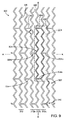
医療装置は、膨張バルーンを有するカテーテルにクリンプされるポリマースキャフォールドを含んでいる。そのスキャフォールドは、よりバランスのとれた、又は、異方性の少ない軸線方向及び半径方向機械的特性を提供するよう編成される2軸方向(A−A、B−B)に延伸されるチューブに起因するモフォロジを有する。スキャフォールドは、体内の末梢血管に埋め込まれるバルーン拡張可能スキャフォールドとして用いるのに適した、改良された機械的特性を有する。The medical device includes a polymer scaffold that is crimped to a catheter having an inflation balloon. The scaffold is a biaxially stretched tube (AA, BB) that is knitted to provide more balanced or less anisotropic axial and radial mechanical properties. It has a morphology due to The scaffold has improved mechanical properties that are suitable for use as a balloon expandable scaffold that is implanted in a peripheral blood vessel in the body.
Description
本発明は薬剤溶出医療装置に関し、より詳細には、本発明は送達バルーンによって拡張されるポリマースキャフォールド(骨格、足場)に関する。 The present invention relates to drug eluting medical devices, and more particularly, the present invention relates to polymer scaffolds (skeletons, scaffolds) that are expanded by a delivery balloon.
半径方向に拡張可能なエンドプロステーゼは、解剖学的管腔に埋め込まれる人工装具である。「解剖学的管腔(anatomicallumen)」とは、血管、尿路及び胆管等の管状臓器の管路(duct)、キャビティ(空洞)のことをいう。ステントはエンドプロステーゼの一例であり、概して円筒形を成し、解剖学的管腔の一部を開通したままに保ち、時に拡張させるよう機能する(ステントの一例を、Lau他の米国特許第6,066,167号で見ることができる)。ステントは、血管内のアテローム硬化性狭窄の治療に用いられることが多い。「狭窄」とは体内の通路又は開口が狭くなっている、又はくびれていることを指す。このような治療において、ステントは血管壁を補強し、血管系における血管形成術後の再狭窄を防ぐ。「再狭窄」は、治療(バルーン血管形成術、ステント埋込術又は弁形成術)が一見して成功した後で再発する血管又は心臓弁の狭窄のことをいう。 A radially expandable endoprosthesis is a prosthesis that is implanted in an anatomical lumen. “Anatomical lumen” refers to ducts and cavities of tubular organs such as blood vessels, urinary tracts, and bile ducts. A stent is an example of an endoprosthesis that is generally cylindrical in shape and serves to keep a portion of the anatomical lumen open and sometimes expand (an example of a stent is disclosed in Lau et al. Can be seen in US Pat. No. 6,066,167). Stents are often used to treat intravascular atherosclerotic stenosis. “Stenosis” refers to a narrowed or constricted passage or opening in the body. In such treatment, the stent reinforces the vessel wall and prevents restenosis after angioplasty in the vasculature. “Restenosis” refers to stenosis of a blood vessel or heart valve that recurs after seemingly successful treatment (balloon angioplasty, stent implantation or valvuloplasty).
ステントを用いる患部または病巣の治療には、ステントの送達及び展開の両方が関与する。「送達」とは、解剖学的管腔を通して病巣等の所望の治療部位までステントを導入及び搬送することをいう。「展開」とは、治療域の管腔内でのステントの拡張のことである。ステントの送達及び展開は、カテーテルの一端にステントを位置決めし、皮膚を貫通してカテーテルの前記一端を解剖学的管腔に挿入し、解剖学的管腔内で所望の治療箇所までカテーテルを進め、ステントを治療箇所で拡張し、カテーテルを管腔から取り出すことにより達成される。 Treatment of an affected area or lesion using a stent involves both delivery and deployment of the stent. “Delivery” refers to the introduction and delivery of a stent through an anatomical lumen to a desired treatment site, such as a lesion. “Deployment” refers to the expansion of the stent within the lumen of the treatment area. Delivery and deployment of the stent involves positioning the stent at one end of the catheter, inserting the end of the catheter through the skin and into the anatomical lumen, and advancing the catheter within the anatomical lumen to the desired treatment site. This is accomplished by expanding the stent at the treatment site and removing the catheter from the lumen.
バルーン膨張ステントの場合には、ステントはカテーテル上に配設したバルーンの周りに取り付けられる。ステントの取り付けには、通常、解剖学的管腔に挿入する前に、ステントをバルーン上へ圧縮つまりクリンプ(圧着又は縮径)することが含まれる。管腔内の治療部位において、バルーンを膨張させることによってステントが拡張される。次いでバルーンを収縮させ、カテーテルをステント及び管腔から引き抜くと、ステントが治療部位に残る。自己拡張ステントの場合、ステントを収縮可能なシース(鞘状体)を介してカテーテルに固定してもよい。ステントが治療部位にあるときにシースを引き抜いて、ステントを自己拡張させてもよい。 In the case of a balloon expandable stent, the stent is mounted around a balloon disposed on the catheter. Stent attachment typically includes compressing or crimping (crimping or shrinking) the stent onto the balloon prior to insertion into the anatomical lumen. At the treatment site in the lumen, the stent is expanded by inflating the balloon. The balloon is then deflated and the catheter is withdrawn from the stent and lumen, leaving the stent at the treatment site. In the case of a self-expanding stent, the stent may be secured to the catheter via a contractible sheath. The sheath may be withdrawn when the stent is at the treatment site to allow the stent to self-expand.
ステントはいくつもの機能上の基本的な要件を満たさねばならない。ステントは、構造的な負荷、例えばステントが展開後に血管の壁を支持するときにかかる半径方向圧縮力、に耐えることができなければならない。したがって、ステントは十分な半径方向強度がなくてはならない。ステントは、展開後にかかるであろう種々の力にもかかわらず、その寿命を通してその大きさと形状を十分に維持しなければならない。特に、ステントは、そうした力にもかかわらず所望の治療期間にわたり、所定の直径で血管を十分に維持しなければならない。治療期間は、血管が所望の直径を維持するのにステントをそれ以上必要としなくなる、血管壁の再構築に必要な時間であればよい。 A stent must meet a number of basic functional requirements. The stent must be able to withstand structural loads, such as the radial compressive force applied when the stent supports the vessel wall after deployment. Therefore, the stent must have sufficient radial strength. A stent must maintain its size and shape well throughout its life, despite the various forces that it may take after deployment. In particular, the stent must adequately maintain the vessel at a predetermined diameter for the desired treatment period despite such forces. The treatment period may be the time required to reconstruct the vessel wall so that the vessel no longer requires a stent to maintain the desired diameter.
半径方向強度は、半径方向の圧縮力に耐えるステントの能力であり、ステントの周方向周りの半径方向降伏強さ及び半径方向スティフネスさに関連する。ステントの「半径方向降伏強さ」又は「半径方向強度」は(本願の目的では)圧縮負荷として理解することができ、その値を超えると降伏応力状態を生じてステント直径が無負荷時の直径に戻らない、すなわちステントに回復不能の変形が残る。半径方向降伏強さを超えると、さらにひどく降伏してしまうことになり、最小限の力を加えるだけでステントは大きく変形する。 Radial strength is the ability of a stent to withstand radial compressive forces and is related to the radial yield strength and radial stiffness around the circumference of the stent. The “radial yield strength” or “radial strength” of a stent can be understood as a compressive load (for purposes of this application), beyond which a yield stress condition occurs and the stent diameter is the unloaded diameter. That is, an unrecoverable deformation remains in the stent. Exceeding the radial yield strength will yield more severely, and the stent will be greatly deformed with minimal force.
半径方向降伏強度を超える前であっても、半径方向圧縮負荷に続いてステントの永久変形を生じるかもしれないが、ステントのどこかに生じるこの程度の永久変形は、血管を半径方向に支持するステントの機能全体に対して重大な影響を及ぼすほど深刻ではない。したがって、場合によっては、当該技術では、「半径方向降伏強度」は、それを超えるとスキャフォールドのスティフネス(堅さ、剛性)が劇的に変化する最大半径方向荷重としてとらえてもよい。「半径方向降伏強度」の単位は、多くの場合、力を長さで除したものであり、単位長さ当たりをベースとした半径方向降伏強度として表される。したがって、単位長さ当たりの半径方向降伏強度、例えばF・N/mmに対して、この値を超えると、結果として、2つの異なる長さL1及びL2を有するステントのスティフネスに著しい変化をもたらす半径方向負荷はそれぞれ、積F×L1及びF×L2となる。しかし、両方とも値Fは同じであるため、簡便な式を用いて、ステントの長さとは無関係な半径方向降伏強度を正しく評価することができる。通常、スティフネスが失われる点を特定する半径方向力は、ステント長さが変化するとき、単位長さ当たりベースではそれ程変化しない。 Even before the radial yield strength is exceeded, permanent deformation of the stent may occur following radial compressive loading, but this degree of permanent deformation occurring somewhere in the stent supports the vessel radially. Not serious enough to have a significant impact on the overall function of the stent. Thus, in some cases, in the art, “radial yield strength” may be viewed as the maximum radial load beyond which the scaffold stiffness (stiffness, stiffness) changes dramatically. The unit of “radial yield strength” is often the force divided by the length and is expressed as the radial yield strength based on unit length. Therefore, for radial yield strength per unit length, eg F · N / mm, exceeding this value results in a radius that significantly changes the stiffness of a stent having two different lengths L1 and L2. The directional loads are the products F × L1 and F × L2, respectively. However, since both have the same value F, a simple formula can be used to correctly evaluate the radial yield strength independent of the length of the stent. Typically, the radial force that identifies the point at which stiffness is lost does not change as much on a per unit length basis as the stent length changes.
一般的に用いられる種類の末梢用ステントは、ニチノール等の超弾性材料製の自己拡張ステントである。この種類の材料は、押しつぶし負荷または長手方向曲げ等の過酷な変形後にその元の構成に戻る能力で知られている。しかし、この様々な自己拡張型ステントの品質は好ましくない。とりわけ、超弾性材料の高弾性が、このステントが支持する血管に「慢性外向き力」(COF)と一般に呼ばれるものを生じる。COFに起因する合併症は、Schwartz,Lewis B.他、「Does Stent Placement have a learning curve: what mistakes do we as operators have to make and how can they be avoided?」、Abbott Laboratories; Abbott Park,IL,USAで検討されている。自己拡張型ステントによって血管に作用するCOFは、自己拡張型ステントによって治療される病巣の高度の再狭窄の主な一因であるとされている。薬を溶出する自己拡張型ステントから送達される抗増殖剤であっても、ステントのCOFによって生じる再狭窄を軽減できないことが分かっている。血管を支持するようバルーンによって塑性変形するステントにはこの欠点がない。実際、バルーンにより拡張されるステントは、超弾性材料製の自己拡張型ステントとは対照的に、残留する外向き力を血管に作用させずに血管を支持する所望の直径まで展開できる望ましい特性を有している。 A commonly used type of peripheral stent is a self-expanding stent made of a superelastic material such as Nitinol. This type of material is known for its ability to return to its original configuration after severe deformation such as crushing loads or longitudinal bending. However, the quality of this variety of self-expanding stents is undesirable. Among other things, the high elasticity of superelastic materials results in what is commonly referred to as “chronic outward force” (COF) in the blood vessels supported by the stent. Complications resulting from COF are Schwartz, Lewis B. et al. Others, “Does Sent Placement have a learning curve: What is do what we do as we have to make and how can be ab ??”, Abet? COF acting on blood vessels with self-expanding stents is believed to be a major contributor to the high degree of restenosis of lesions treated with self-expanding stents. It has been found that even anti-proliferative agents delivered from drug-eluting self-expanding stents cannot alleviate restenosis caused by stent COF. A stent that is plastically deformed by a balloon to support a blood vessel does not have this disadvantage. In fact, balloon-expanded stents, in contrast to self-expanding stents made of superelastic materials, have the desirable properties of being able to expand to the desired diameter that supports the vessel without exerting residual outward forces on the vessel. Have.
US2010/0004735に記載されているようなバルーン膨張型ポリマースキャフォールドは、生分解性、生体吸収性、生体再吸収性、または生体内分解性のポリマーからできている。生分解性、生体吸収性、生体再吸収性、生体溶解性、または生体内分解性という用語は、分解、吸収、再吸収、または侵食されて、埋込部位から消え去る材料またはステントの性質を指す。US2010/0004735に記載されているポリマースキャフォールドは、例えば、金属ステントとは対照的に、限られた期間のみ体内に残ることを意図されている。そのようなスキャフォールドは、生分解性、または生体内分解性のポリマーで作られる。多くの治療用途では、例えば血管の開通性及び/又は薬剤送達の維持という意図した機能が達成されるまでの限られた期間中は、ステントを体内に置いておく必要があろう。さらに、生分解性スキャフォールドは金属ステントと比べて、後期の血栓症発生率の低下につながる可能性があり、解剖学的管腔の治癒率を改善できることがわかっている。これらの場合、金属ステントとは対照的に、血管内での人工器官の存在を限られた期間とするために、ポリマースキャフォールド、特には生体内分解性ポリマースキャフォールドを用いて血管を治療したいという要望がある。しかし、ポリマースキャフォールドを開発する場合、克服すべき課題は多い。 Balloon inflatable polymer scaffolds as described in US2010 / 0004735 are made of biodegradable, bioabsorbable, bioresorbable, or biodegradable polymers. The terms biodegradable, bioabsorbable, bioresorbable, biosoluble, or biodegradable refer to the nature of a material or stent that degrades, absorbs, resorbs, or erodes away from the implantation site. . The polymer scaffold described in US 2010/0004735 is intended to remain in the body only for a limited period of time, in contrast to, for example, metal stents. Such scaffolds are made of biodegradable or biodegradable polymers. In many therapeutic applications, it may be necessary to leave the stent in the body for a limited period of time until the intended function of, for example, maintaining vascular patency and / or drug delivery is achieved. Furthermore, biodegradable scaffolds have been shown to lead to a lower incidence of late thrombosis compared to metal stents, and can improve the healing rate of anatomical lumens. In these cases, in contrast to metal stents, we want to treat blood vessels with polymer scaffolds, especially biodegradable polymer scaffolds, in order to have a limited period of prosthesis in the blood vessels There is a request. However, there are many challenges to overcome when developing polymer scaffolds.
ポリマースキャフォールドへの使用が考慮されるポリマー材料、例えば、ポリ(L−ラクチド)(「PLLA」)、ポリ(L−ラクチド−co−グリコリド)(「PLGA」)、D−ラクチドが10%未満のポリ(D−ラクチド−co−グリコリド)又はポリ(L−ラクチド−co−D−ラクチド)(「PLDLA」)、及びPLLA/PDLA立体錯体については、ステントの形成に用いられる金属材料との比較を通じて、以下のいくつかの方法で説明できる。適切なポリマーの強度重量比は低く、これは、金属と同等の機械的特性を得るにはより多くの材料が必要であることを意味している。したがって、ストラット(支柱、構造部材)は、ステントが所望の半径で管腔壁を支持するのに必要な強度を持つべくより肉厚で、より幅広にしなければならない。このようなポリマー製のスキャフォールドも脆い傾向があり、または限定的な破壊靭性しか有さない。材料に固有の異方性及び頻度(速度)依存性の非弾性特性(すなわち、材料の強度/スティフネスが、材料が変形する率(速度)に依存して変化する)は、ポリマー、特に、PLLA又はPLGA等の生体吸収性ポリマーとの働きを複雑にしている。 Polymer materials considered for use in polymer scaffolds, eg, poly (L-lactide) (“PLLA”), poly (L-lactide-co-glycolide) (“PLGA”), less than 10% D-lactide Poly (D-lactide-co-glycolide) or poly (L-lactide-co-D-lactide) ("PLDLA") and PLLA / PDLA steric complexes compared to the metal materials used to form the stent This can be explained in several ways. A suitable polymer has a low strength to weight ratio, which means that more material is required to obtain mechanical properties comparable to metals. Thus, the struts (struts, structural members) must be thicker and wider to have the strength necessary for the stent to support the lumen wall with the desired radius. Such polymer scaffolds also tend to be brittle or have limited fracture toughness. The inherent anisotropy and frequency (rate) dependent inelastic properties of the material (ie, the strength / stiffness of the material changes depending on the rate at which the material is deformed (rate)), the polymer, especially PLLA Or the function with bioabsorbable polymers such as PLGA is complicated.
冠動脈中への埋め込みを意図されたポリマースキャフォールド、即ち冠血管スキャフォールドのためのチューブを作成する加工ステップについて、さまざまな研究がなされてきた。US2011/0062638(代理人整理番号62571.390)を参照。これらの研究で調べられた特性は、例えば、半径方向強度(radialstrength)、半径方向スティフネス(堅さ、剛性)(radial stiffness)、極限ひずみ、半径方向に拡張されたスキャフォールドの破断、壁厚方向にわたる均質性であった。これらの研究の報告には、軸線方向拡張及び半径方向拡張の程度を異にする比の組み合わせ(US2011/0062638の表1)で変化させることによって機械的特性がどのように影響を受けるかに関する報告が含まれている。冠血管スキャフォールドには、半径方向延伸が約400%そして軸線方向延伸が約20%の押出ポリマーチューブが用いられてきた。この2軸延伸チューブはレーザを用いて切断されて冠血管スキャフォールドになる。 Various studies have been done on the processing steps to create a polymer scaffold intended for implantation in the coronary artery, ie a tube for the coronary scaffold. See US 2011/0062638 (Attorney Docket No. 62571.3390). The properties examined in these studies include, for example, radial strength, radial stiffness, ultimate strain, radially expanded scaffold fracture, wall thickness direction The homogeneity was over. These studies report on how mechanical properties are affected by varying ratio combinations (Table 1 of US2011 / 0062638) with different degrees of axial and radial expansion. It is included. For coronary scaffolds, extruded polymer tubes with about 400% radial stretch and about 20% axial stretch have been used. The biaxially stretched tube is cut using a laser to form a coronary scaffold.
冠動脈に埋め込まれるステントは、血液が鼓動する心臓へ、及びそこから圧送される際の血管の周期的な収縮及び膨張に起因する、典型的には、本質的に周期性の半径方向荷重を主として受ける。しかし、末梢血管又は冠動脈の外側にある血管、例えば、腸骨動脈、大腿動脈、膝窩動脈、腎動脈、及び鎖骨下動脈に埋め込まれるステントは、半径方向力と、押し潰し又はピンチング(締め付け)の荷重、の両方を支えることができねばならない。これらの種類のステントは、身体の表面に近い血管に埋め込まれる。これらのステントが身体の表面に近いため、特に押し潰しまたはピンチング荷重を受けやすく、これらの荷重は、ステントを部分的に又は完全に潰し、それによって血管内の流体フローを閉塞してしまう。 Stents implanted in coronary arteries are typically primarily subject to essentially periodic radial loads due to the cyclic contraction and expansion of blood vessels as blood is pumped into and out of the heart. receive. However, stents implanted in peripheral blood vessels or blood vessels outside the coronary arteries, such as the iliac, femoral, popliteal, renal, and subclavian arteries, are subject to radial forces and crushing or pinching. Must be able to support both of the load. These types of stents are implanted in blood vessels close to the body surface. Because these stents are close to the surface of the body, they are particularly susceptible to crushing or pinching loads, which can partially or completely collapse the stent, thereby occluding fluid flow in the blood vessel.
主に半径方向荷重の影響に対抗するように設計された冠血管スキャフォールドと比べて、末梢血管スキャフォールドは、Duerig、Tolomeo、WholeyのOverview of superelastic stent Design、Min Invas Ther & Allied Technol 9(3/4)、pp.235−246(2000)及びStoeckel、Pelton、DuerigのSelf−Expanding Nitinol Stents − Material and Design Considerations、European Radiology(2003)において、金属製ステントに対して検討されている、押し潰し又はピンチング荷重と半径方向荷重との間の著しい相違を考慮しなければならない。それに対応してステントの押し潰し及び半径方向スティフネス特性も劇的に変わってくる。したがって、ある程度の半径方向スティフネスを有するステントは、一般的に言って、そのステントが持つピンチング・スティフネスの程度も示し得ない。これら2つのスティフネス特性は同一でもなく、同様でさえもない。 Compared to coronary scaffolds designed primarily to counter the effects of radial loading, peripheral vascular scaffolds have been developed by Duerig, Toromeo, Whore's Overview of superstress Design, Min Invas Then 3 Tal & Allied Al / 4), pp. 235-246 (2000) and Stoeckel, Pelton, Duelig's Self-Expanding Nitinol Stents-Material and Design Considations, European Radiology (2003), crushed and crushed or pinned for metal stents Considerable differences between loads must be taken into account. Correspondingly, the crushing and radial stiffness characteristics of the stent change dramatically. Thus, a stent having a certain degree of radial stiffness generally cannot show the degree of pinching stiffness that the stent has. These two stiffness characteristics are not identical or even similar.
押し潰し荷重に加えて、末梢血管用のスキャフォールドは、冠血管スキャフォールドとは対照的に、全く異なる時間変化負荷を経験する。この経験は、ステントの用途適合性の従来の尺度、即ちその半径方向強度/スティフネスが、末梢血管埋込みスキャフォールド(「末梢血管スキャフォールド」)が、必要とする間、末梢血管内で支持を提供する時間依存性の機械的特性を有するかどうかの正確な尺度ではないという範囲の経験である。これは、末梢血管用スキャフォールドが冠血管用スキャフォールドとは著しく異なる環境に置かれるからである。血管のサイズはより大きい。そして、血管は、特に付属肢(appendage)の近くに位置する場合、より大きく動く。したがって、末梢血管用のスキャフォールドは、軸線方向負荷、曲げ負荷、ねじり負荷、及び半径方向負荷の組み合わせを含む、より複雑な負荷に耐える必要がある。例えば、Bosiers, M.及びSchwartz, L.、Development of Bioresorbable Scaffolds for the Superficial Femoral Artery,SFA: Contemporary Endovascular Management(「Interventions in the SFA」欄)を参照。末梢血管埋込みステント及びスキャフォールドに対するこうした挑戦も、関連する挑戦も、US2011/0190872(代理人用整理番号104584.10)で検討されている。特に、歩行に伴う軸線方向負荷が、スキャフォールドストラットの破損の主要原因であることが見出された。 In addition to crushing loads, scaffolds for peripheral vessels experience a completely different time-varying load as opposed to coronary scaffolds. This experience shows that the traditional measure of stent applicability, namely its radial strength / stiffness, provides support within the peripheral vessel while the peripheral vessel implant scaffold (“peripheral vessel scaffold”) requires it. It is a range of experience that is not an accurate measure of whether it has time-dependent mechanical properties. This is because the peripheral vascular scaffold is placed in a significantly different environment from the coronary scaffold. The vessel size is larger. And blood vessels move more greatly, especially when located near the appendage. Thus, peripheral vessel scaffolds need to withstand more complex loads, including combinations of axial, bending, torsional, and radial loads. For example, Bosiers, M.M. And Schwartz, L .; , Development of Bioresolvable Scaffolds for the Superficial Primary Art, SFA: Contemporary Endovascular Management (see “Interventions in the SFA” column). These and related challenges for peripheral vascular implant stents and scaffolds are discussed in US2011 / 0190872 (Attorney Docket No. 104584.10). In particular, the axial load associated with walking has been found to be a major cause of scaffold strut failure.
支持をそれ以上必要としなくなるまで、血管に対する機械的支持を提供するよう十分に長い期間その構造的完全性を維持できる、末梢血管を治療するための人工器官(プロステーゼ、prosthesis)を開発する必要がある。リコイル(recoil 反動・反跳)量が調節された又は低減された、しかも血管運動の程度が高い領域に必要な所望の軸線方向及び半径方向強度並びに靭性を提供できるような人工器官を更に開発する必要がある。 There is a need to develop a prosthesis to treat peripheral blood vessels that can maintain its structural integrity long enough to provide mechanical support to the blood vessels until no further support is needed is there. Further develop a prosthesis that can provide the desired axial and radial strength and toughness needed in areas where the amount of recoil (recoil recoil / recoil) is controlled or reduced and where the degree of vasomotion is high There is a need.
これらのニーズに応じて、末梢血管に埋め込まれるスキャフォールドに課せられた要求を充たすために好適な機械的特性を有する、2軸延伸チューブから形成される、末梢血管埋込み可能な生体内分解性ポリマースキャフォールドが提供される。バランスよく組み合わせられ、等方性である又は異方性の少ない2軸延伸チューブを有し、(2軸延伸中の)全ひずみの程度が相対的に高い末梢血管スキャフォールドを形成して判明したことは、そのようなスキャフォールドは、構造支持を提供すること、そして血管内でのその構造的完全性を維持する、より高い能力を備えるという点である。 In accordance with these needs, a peripheral vessel implantable biodegradable polymer formed from a biaxially stretched tube having suitable mechanical properties to meet the demands imposed on scaffolds implanted in peripheral vessels A scaffold is provided. Found to form a peripheral vascular scaffold with a well-balanced, isotropic or less anisotropic biaxially stretched tube and a relatively high degree of total strain (during biaxial stretching) That is, such a scaffold has a higher ability to provide structural support and maintain its structural integrity within the blood vessel.
冠血管スキャフォールドへと形成されるチューブは、400%の半径方向延伸及び20%の軸線方向延伸を含む延伸プロセスに従って作成され、それによって、軸線方向対半径方向の荷重方向に関して非常に大きい異方性配向を有するチューブを製造する、即ち、チューブの材料は主に周方向ポリマー配向を有する。試験において、末梢血管に対して、よりバランスのとれた2軸ポリマー配向を持つスキャフォールドは疲労破壊耐性を向上できることが見出された。実際に、軸線方向疲労破壊耐性は、より多くの2軸ポリマー配向(延伸比400/200)を持つチューブを用いて向上したことが発見された。さらに、破損時の伸びは、異方性チューブの材料が2時間を超えて水分に曝露されると、現行の延伸プロセス(400/45)により製造されるチューブに対して軸線方向及び周方向の配向に劇的な変化が生ずることが発見された。一方、乾燥した材料に対しては、ほとんど差がなかった。また、少なくとも6日間の水(37℃)への曝露後、よりバランスのとれた、又は均一な2軸ポリマー配向(例えば、延伸比2、1、又は2から1の間)を有するチューブについて、破損時の伸びは、軸線方向と周方向との間の相違は何ら観察されなかった。
The tube formed into the coronary scaffold is made according to a stretching process that includes 400% radial stretching and 20% axial stretching, so that it is very anisotropic with respect to the axial vs. radial load direction. A tube having a unidirectional orientation, ie, the material of the tube has a predominantly circumferential polymer orientation. In testing, it was found that a scaffold with a more balanced biaxial polymer orientation for peripheral blood vessels can improve fatigue fracture resistance. Indeed, it was discovered that axial fatigue fracture resistance was improved using tubes with more biaxial polymer orientation (
調節(400%半径方向及び45%軸線方向)と400%及び200%とを比較する試験では、後者は軸線方向のひずみがより大なので、半径方向強度/スティフネスをいくらか欠いたことが示された。軸線方向の破損耐性をより高めることによって、半径方向の機械的強度がある程度失われる。しかし、(機械的強度の)低下はそれ程でもなかった。加えて、(400%/200%)延伸は、1時間後のリコイルを向上させ、又そのスキャフォールドは、リコイルが24時間後に横ばいとなるレベルに迅速に達する。そのレベルは、制御群と比較した場合に、改善されたものである。 Tests comparing the adjustment (400% radial and 45% axial) with 400% and 200% showed that the latter lacked some radial strength / stiffness due to greater axial strain. . By further increasing the axial damage resistance, some mechanical strength in the radial direction is lost. However, the decrease in mechanical strength was not so great. In addition, stretching (400% / 200%) improves recoil after 1 hour and the scaffold quickly reaches a level where the recoil levels off after 24 hours. That level is improved when compared to the control group.
本発明の一の態様によれば、軸線方向疲労試験、半径方向強度、及びリコイルにより観察された結果から、2軸方向の異方性の少ないチューブの材料が、末梢血管用の良好なスキャフォールドを生成することを示唆している。好ましい延伸比は約2であり、これは約1又は1未満の、37℃で6日間浸漬後の伸び比(周方向/軸線方向)を生じる。 According to one aspect of the present invention, from the results observed by axial fatigue testing, radial strength, and recoil, a tube material with low biaxial anisotropy is a good scaffold for peripheral blood vessels. Suggests to generate. A preferred draw ratio is about 2, which results in an elongation ratio (circumferential / axial) after 6 days immersion at 37 ° C. of about 1 or less.
本発明の一態様によれば、リング構造を形成するバルーン拡張型スキャフォールドが存在する。スキャフォールドは、半径方向対軸線方向の延伸の比が約2又は2未満であるバランスのとれた2軸延伸チューブから形成される。各リングは、2つ以下のリンクによって隣接するリングに接続され、各リングは、ストラット(strut)(支柱、構造部材))構成要素によって形成される少なくとも8つの冠部又は12の冠部を有している。 According to one aspect of the invention, there is a balloon expandable scaffold that forms a ring structure. The scaffold is formed from a balanced biaxially stretched tube with a radial to axial stretch ratio of about 2 or less. Each ring is connected to adjacent rings by no more than two links, and each ring has at least eight crowns or twelve crowns formed by strut components. doing.
本発明の第1の態様によれば、バルーン拡張され、末梢血管に埋め込まれるスキャフォールド、かかるスキャフォールドを作成する方法、又はバルーンにクリンプ(圧縮、縮径)されるスキャフォールドがあり、2軸延伸、全ひずみ、及び/又は破損時における半径方向対軸線方向伸び比を有するスキャフォールドは、他の機械的特性に重大な悪影響を及ぼすことなく、軸線方向における向上した靭性を与える。 According to a first aspect of the present invention, there is a scaffold that is balloon-expanded and embedded in a peripheral blood vessel, a method for making such a scaffold, or a scaffold that is crimped (compressed, reduced in diameter) on a balloon. A scaffold having a radial to axial stretch ratio at stretch, total strain, and / or failure provides improved toughness in the axial direction without significantly adversely affecting other mechanical properties.
本発明の第2の態様によれば、バルーン拡張され、末梢血管に埋め込まれるスキャフォールド、又はかかるスキャフォールドを作成する方法、又はバルーンにクリンプされるスキャフォールドがあり、2軸延伸、全ひずみ、及び/又は破損時における半径方向対軸線方向伸び比を有するスキャフォールドは、急性期(短時間)、埋込みから1時間、1日、及び埋込みから1週間の間に、向上したリコイル特性を提供する。 According to a second aspect of the present invention, there is a scaffold that is balloon-expanded and embedded in a peripheral blood vessel, or a method for making such a scaffold, or a scaffold that is crimped to a balloon, biaxially stretched, total strain, And / or a scaffold having a radial to axial stretch ratio at failure provides improved recoil characteristics during the acute phase (short time), 1 hour from implantation, 1 day, and 1 week from implantation. .
本発明の第3の態様によれば、バルーン拡張され、末梢血管に埋め込まれるスキャフォールド、かかるスキャフォールドを作成する方法、又はバルーンにクリンプされるスキャフォールドがあり、スキャフォールドは2軸延伸、全ひずみ、及び/又は破損時における半径方向対軸線方向伸び比を有し、スキャフォールドはリング当たり最大でも2つのリンクと8又は12の冠部を有する。 According to a third aspect of the invention, there is a scaffold that is balloon-expanded and implanted in a peripheral blood vessel, a method of making such a scaffold, or a scaffold that is crimped to a balloon, the scaffold being biaxially stretched, fully It has a radial to axial stretch ratio at strain and / or failure and the scaffold has at most 2 links and 8 or 12 crowns per ring.
本発明の第4の態様によれば、バルーン拡張され、末梢血管に埋め込まれるスキャフォールド、かかるスキャフォールドを作成する方法、又はバルーンにクリンプされるスキャフォールドがあり、スキャフォールドは2軸延伸、全ひずみ、及び/又は破損時における半径方向対軸線方向伸び比を有し、スキャフォールドは、クリンプ前直径を有するか、又は5mmを超えるか、又は拡張直径又は拡張後直径よりも約1.1、1.0、1.2、1.3、1.4、1.5又は約1.0〜1.5倍大きいチューブ直径からできており、クリンプされた直径よりも約2、2.5、3、又は3.5倍大きい拡張された直径又はクリンプ前直径;及び/又は、7mmの外径及び/又は0.279mmの壁厚を有する。
According to a fourth aspect of the present invention, there is a scaffold that is balloon-expanded and embedded in a peripheral blood vessel, a method of making such a scaffold, or a scaffold that is crimped to a balloon, the scaffold is biaxially stretched, fully Having a radial to axial stretch ratio at strain and / or failure, and the scaffold has a pre-crimp diameter, or greater than 5 mm, or about 1.1 than the expanded or post-expanded diameter; 1.0, 1.2, 1.3, 1.4, 1.5 or about 1.0 to 1.5 times larger tube diameter, about 2, 2.5, than the crimped
本発明の第5の態様によれば、バルーン拡張され、末梢血管に埋め込まれるスキャフォールド、かかるスキャフォールドを作成する方法、又はバルーンにクリンプされるスキャフォールドがあり、2軸延伸、全ひずみ、及び/又は破損時における半径方向対軸線方向伸び比を有するスキャフォールドは、10%のリコイル量及び拡張直径の90%を超える拡張後直径を生じる。 According to a fifth aspect of the present invention, there is a scaffold that is balloon-expanded and implanted in a peripheral blood vessel, a method of making such a scaffold, or a scaffold that is crimped to a balloon, and biaxial stretching, total strain, and A scaffold with a radial to axial stretch ratio at failure yields a 10% recoil amount and a post-expansion diameter greater than 90% of the expansion diameter.
本発明の第1、第2、第3、第4、及び第5の態様のそれぞれに対して、2軸延伸は、半径方向において約400〜500から、そして、軸線方向において約150〜200からの範囲に及んでいてもよく、RE/AE(半径方向延伸/軸線方向延伸)の比は、約2と1との間、2.5対1、3対1、及び4対1であってもよい。 For each of the first, second, third, fourth and fifth aspects of the present invention, the biaxial stretching is from about 400 to 500 in the radial direction and from about 150 to 200 in the axial direction. The ratio of RE / AE (radial stretch / axial stretch) is between about 2 and 1, 2.5 to 1, 3 to 1, and 4 to 1. Also good.
2軸延伸チューブ、スキャフォールド、又はバルーンにクリンプされるスキャフォールドに関する本発明の第1、第2、第3、第4、及び第5の態様のそれぞれに対して、軸線方向及び半径方向におけるスキャフォールド/チューブの材料のモフォロジ(形態と構造)は、約2、2未満、1未満、又は2〜1の間の半径方向対軸線方向延伸比に起因する、即ち前記比から得られるポリマー結晶の好ましい配向を備え;及び/又は、その材料は約1又は1未満の破損時における半径方向対軸線方向伸び比を有する。 For each of the first, second, third, fourth, and fifth aspects of the present invention relating to a biaxially stretched tube, scaffold, or scaffold crimped to a balloon, the axial and radial scaffolds, respectively. The morphology of the fold / tube material (morphology and structure) is due to a radial to axial stretch ratio of less than about 2, less than 2, less than 1, or between 2-1, ie, the polymer crystal resulting from said ratio With a preferred orientation; and / or the material has a radial to axial stretch ratio at failure of about 1 or less.
本発明の別の態様によれば、バランスのとれた2軸延伸チューブから形成され、隣接するリング構造を接続する最大でも2つのリンクを有し、スキャフォールドが血管に機械的支持を提供するのに必要な期間、例えば、埋込み後、最初の約1、2、又は3ヶ月間のスキャフォールドの疲労寿命を延ばすよう、増加した数の冠部を持っている、又は持っていないスキャフォールドが提供される。テストにより、末梢血管に埋め込まれるスキャフォールドに対して、特に、付属肢の動脈内に位置するスキャフォールドに対して、スキャフォールド構造の損傷は、多くの場合、繰り返し行われる軸線方向圧縮/伸張及び曲げにより発生することが明らかとなった。スキャフォールドは一般に、半径方向、軸線方向、曲げ及びねじり荷重の複合及び時間変動の組み合わせを受けるが、従来のスキャフォールド設計は、繰り返しによる周期的な軸線方向荷重及び曲げ荷重、例えば、6か月間にわたる歩行に相当すると考えられる500,000サイクルの7%の軸線方向圧縮/伸張により、亀裂形成を大変に受けやすいことがわかっている。リング構造間で繰り返される衝突、リンクの長手方向の座屈(曲がり)、又は軸線方向スティフネスと曲げスティフネスの低減から生じる可能性のある他の挙動は、in−vivo(体内に関する)研究に基づいて、血管支持又はスキャフォールド完全性に対して重大な悪影響を及ぼすことが見出された。 According to another aspect of the present invention, the scaffold provides mechanical support to the blood vessel formed from a balanced biaxially stretched tube and having at most two links connecting adjacent ring structures. Provides a scaffold with or without an increased number of crowns to extend the fatigue life of the scaffold for the period required for, eg, the first approximately 1, 2, or 3 months after implantation Is done. Tests show that for scaffolds implanted in peripheral blood vessels, and in particular for scaffolds located within the arteries of the appendages, scaffold structure damage is often repeated axial compression / extension and It became clear that it occurred by bending. Scaffolds are generally subject to a combination of radial, axial, bending and torsional loads and a time-varying combination, but traditional scaffold designs are subject to repeated cyclic axial and bending loads, eg 6 months It has been found that 7% axial compression / extension of 500,000 cycles, which is thought to correspond to long walking, is very susceptible to crack formation. Other behaviors that may result from repeated collisions between ring structures, longitudinal buckling (bending) of links, or reduction of axial and bending stiffness are based on in-vivo studies. It has been found to have a significant adverse effect on vascular support or scaffold integrity.
別の実施の形態によれば、末梢血管に埋め込まれる医療装置は、半径方向に拡張されるポリマーチューブから形成されるバルーン拡張スキャフォールドを含み、リンクによって相互接続されるリングのネットワーク(網目構造)を形成するスキャフォールドは、リング当たり少なくとも8又は12の冠部と、隣接するリングの実質的にすべてのペア(対)に接続する最大でも2つのリンクとを含み、スキャフォールドのいずれのリングに対しても、リンクに接続される各冠部の各側部(両側)に、等しい数の支持されていない冠部が存在する。2つのリンクにより、構造部は、軸方向の荷重と曲げを受けている間に誘導される応力を良好に吸収/分布させることができる。さらに、構造部の総疲労寿命は、2つのリンクが用いられた場合に著しく増加することが見出された。加えて、リンクを中心とする冠部又は頂部の対称性は、応力をより均一に分布させる手助けをするか、又は、冠部付近の応力集中を減らして、軸方向の荷重と曲げを受けている間の疲労寿命の向上を手助けする。 According to another embodiment, a medical device implanted in a peripheral blood vessel includes a balloon expansion scaffold formed from a radially expanded polymer tube, and a network of rings interconnected by links Includes at least eight or twelve crowns per ring and at most two links connecting to virtually every pair of adjacent rings, on any ring of the scaffold Again, there are an equal number of unsupported crowns on each side (both sides) of each crown connected to the link. The two links allow the structure to better absorb / distribute stresses induced during axial loading and bending. Furthermore, it has been found that the total fatigue life of the structure is significantly increased when two links are used. In addition, the symmetry of the crown or top about the link helps to distribute the stress more evenly, or reduces stress concentration near the crown, subject to axial loading and bending. Helps improve fatigue life while you are.
本明細書に記載したすべての刊行物及び特許出願は、あたかもそれぞれ個々の刊行物及び特許出願が具体的に、そして個々に引用して組み込まれるよう指示されたものと同等の範囲で、引用してここに組み込む。組み込まれる刊行物又は特許と本明細書との間に用語及び/又は語句のいずれかの一貫性のない使用が存在する場合、これらの用語及び/又は語句は、本明細書中で用いられる用法と一致する意味を有する。 All publications and patent applications mentioned in this specification are referenced to the same extent as if each individual publication and patent application were specifically and individually indicated to be incorporated by reference. Incorporate here. Where there is an inconsistent use of any terms and / or phrases between an incorporated publication or patent and this specification, these terms and / or phrases may be used as used herein. Has the same meaning as
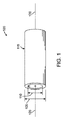
以下の通りに、開示を進めていく。先ず、後に続く開示で用いることになる用語を定義する。前駆体から変形ポリマーチューブを形成するプロセスの実施の形態について開示する。開示によれば、潰れ回復可能な及びバルーン拡張可能なスキャフォールドは、破壊靭性を含むスキャフォールドの機械的特性の強化を目的とするプロセスによって形成されるチューブ(図1)から切り取られる。このプロセスを検討した後、スキャフォールドに加工されるチューブに対する最良の又は改良された2軸延伸を決定するためになされた研究について述べる。最後に、2つの好ましいスキャフォールドの設計を開示する。 We will proceed with disclosure as follows. First, terms that will be used in subsequent disclosures are defined. An embodiment of a process for forming a deformed polymer tube from a precursor is disclosed. According to the disclosure, a collapsible recoverable and balloon expandable scaffold is cut from a tube (FIG. 1) formed by a process aimed at enhancing the mechanical properties of the scaffold, including fracture toughness. After reviewing this process, the work done to determine the best or improved biaxial stretching for a tube processed into a scaffold is described. Finally, two preferred scaffold designs are disclosed.
本開示のために、以下の用語及び定義を適用する。 For purposes of this disclosure, the following terms and definitions apply.
用語「約」は、記載された値よりも10%、5%、もしくは2%大あるいは未満、又は記載の平均値からの1シグマのばらつきを意味する。 The term “about” means 10%, 5%, or 2% greater or less than the stated value, or 1 sigma variation from the stated mean value.
「基準血管直径」(RVD)は血管の病変部位に隣接する領域内の血管の直径であって、その領域は正常に見える、又はごくわずかに病変があるように見える領域である。 “Reference vessel diameter” (RVD) is the diameter of a blood vessel in an area adjacent to the lesion site of the blood vessel, which is the area that appears normal or appears to have very little lesion.
「最小管腔直径」(MLD)は、最も径が縮小した部位における血管病変部位の直径である。 “Minimum lumen diameter” (MLD) is the diameter of the vascular lesion site at the site with the smallest diameter.
%「直径再狭窄」(%DS)は、基準血管直径と最小管腔直径との間の差の百分率、すなわち(RVD−MLD)/RVDである。 % “Diameter Restenosis” (% DS) is the percentage difference between the reference vessel diameter and the minimum lumen diameter, ie (RVD−MLD) / RVD.
「急(急性)増加」は、処置前と処置後の最小管腔直径の差として定義される。 “Steep (acute) increase” is defined as the difference in minimum lumen diameter before and after treatment.
「後期損失」は、処置後又は経皮的冠インターベンション(PCI)後の最小管腔直径とフォローアップ(追跡検査)時の最小管腔直径との差として定義される。 “Late loss” is defined as the difference between the minimum lumen diameter after treatment or percutaneous coronary intervention (PCI) and the minimum lumen diameter at follow-up.
「膨張直径」又は「拡張直径」とは、支持バルーンが膨張してスキャフォールドをそのクリンプされた構成から拡張し、スキャフォールドを血管内に埋め込む場合にスキャフォールドが達する直径を指す。膨張直径は、公称バルーン直径を超えて膨張した後のバルーン直径を指してもよい。それは、例えば、6.5mmのバルーンが約7.4mmの膨張後直径を有する、あるいは6.0mmのバルーンが約6.5mmの膨張後直径を有するということである。バルーンの公称直径対膨張後直径の比は1.05から1.15の範囲であってよい(すなわち、膨張後直径は、公称バルーン直径より5%から15%大きくてもよい)。バルーン圧力により膨張直径に達した後のスキャフォールド直径は、主に、スキャフォールドの製造及び加工の方法、スキャフォールドの材料並びにスキャフォールドの設計の何れか又はすべてに関係するリコイル(跳ね返り)効果によってある程度まで径が縮小する。 “Inflated diameter” or “expanded diameter” refers to the diameter that the scaffold reaches when the support balloon is inflated to expand the scaffold from its crimped configuration and implant the scaffold within a blood vessel. The inflation diameter may refer to the balloon diameter after inflation beyond the nominal balloon diameter. That is, for example, a 6.5 mm balloon has an expanded diameter of about 7.4 mm, or a 6.0 mm balloon has an expanded diameter of about 6.5 mm. The ratio of the nominal diameter of the balloon to the diameter after inflation may range from 1.05 to 1.15 (ie, the diameter after inflation may be 5% to 15% greater than the nominal balloon diameter). After reaching the inflated diameter due to balloon pressure, the scaffold diameter is mainly due to the recoil effect related to the method of manufacturing and processing the scaffold, the material of the scaffold and the design of the scaffold. The diameter is reduced to some extent.
スキャフォールドの「膨張後直径」(PDD)とは、その拡張直径に達した後、バルーンを患者の血管系から除去した後のスキャフォールドの直径を指す。PDDは、リコイル効果の原因となる。例えば、急性PDDとは、スキャフォールド内の急性リコイルの原因となるスキャフォールド直径を指す。 The “post-expansion diameter” (PDD) of the scaffold refers to the diameter of the scaffold after its balloon is removed from the patient's vasculature after reaching its expanded diameter. PDD causes the recoil effect. For example, acute PDD refers to the scaffold diameter that causes acute recoil within the scaffold.
「クリンプ前直径」は、チューブ又はバルーンへクリンプされる前のスキャフォールドの外径(OD)を意味する。同様に、「クリンプ直径」は、バルーンへリンピングされたときのスキャフォールドのODを意味する。「クリンプ前直径」は、クリンプ後直径の2、2.5、3.0倍であってもよく、拡張直径又は膨張後直径の約0.9、1.0、1.1、1.3倍及び約1から1.5倍であってもよい。 “Pre-crimp diameter” means the outer diameter (OD) of the scaffold before it is crimped to a tube or balloon. Similarly, “crimp diameter” means the OD of the scaffold when it is rimped into the balloon. The “pre-crimp diameter” may be 2, 2.5, 3.0 times the post-crimp diameter and is about 0.9, 1.0, 1.1, 1.3 of the expanded or expanded diameter. It may be double and about 1 to 1.5 times.
「リコイル」は、材料の塑性/非弾性変形後の材料の反応を意味する。スキャフォールドがその弾性域を超えて半径方向に良好に変形し、外圧(例えば、管腔表面へのバルーン圧)が除去された場合、スキャフォールド直径は、外圧がかけられる前のその初期状態に戻る傾向がある。したがって、スキャフォールドはかけられたバルーン圧力により半径方向に拡張され、バルーンが除去された場合、スキャフォールドは、バルーン圧力がかけられる前のより小さな直径、すなわちクリンプ直径に向かって戻る傾向がある。埋込後30分以内のリコイルが10%で、拡張直径が6mmであるスキャフォールドは、5.4mmの急な膨張後直径を有する。バルーン拡張スキャフォールドに対するリコイル効果は長期間にわたって発生し得る。スキャフォールドの埋込後検査では、埋込後約1週間にわたりリコイルが増加することが分かっている。特に記載のない限り、「リコイル」は、スキャフォールドの半径方向(軸線方向又は長手方向に対立する方向)に沿うリコイルを意味する。 “Recoil” means the reaction of a material after plastic / inelastic deformation of the material. If the scaffold is well deformed radially beyond its elastic range and external pressure (eg, balloon pressure on the lumen surface) is removed, the scaffold diameter will return to its initial state before external pressure is applied. There is a tendency to return. Thus, the scaffold is radially expanded by the applied balloon pressure, and when the balloon is removed, the scaffold tends to return towards a smaller diameter before the balloon pressure is applied, ie the crimp diameter. A scaffold with 10% recoil within 30 minutes after implantation and an expanded diameter of 6 mm has a sharp post-expansion diameter of 5.4 mm. The recoil effect on the balloon-expanded scaffold can occur over a long period of time. Scaffold post-implantation studies have shown that recoil increases for approximately one week after implantation. Unless otherwise specified, “recoil” means a recoil along the radial direction of the scaffold (direction opposite to the axial direction or the longitudinal direction).
「急性リコイル」は、血管への埋込後、最初の約30分以内のスキャフォールド直径減少率として定義される。 “Acute recoil” is defined as the rate of scaffold diameter reduction within the first approximately 30 minutes after implantation into a blood vessel.
ガラス転移温度(本明細書中「Tg」という)は、ポリマーのアモルファス領域が大気圧において脆いガラス状態から固体変形可能又は延性状態に変化する温度である。言い換えれば、Tgは、ポリマー鎖におけるセグメント運動が始まる温度に相当する。所定ポリマーのTgは加熱速度に依存し、ポリマーの熱履歴の影響を受ける。その上、ポリマーの化学構造は、ポリマー鎖の運動性に影響を与えることによって、ガラス転移に重大な影響を及ぼす。Tgの下限はTg−LOWであり、中間点はTg−MID及び上限はTg−HIGHである。 The glass transition temperature (referred to herein as “Tg”) is the temperature at which the amorphous region of the polymer changes from a brittle glass state to a solid deformable or ductile state at atmospheric pressure. In other words, Tg corresponds to the temperature at which segment motion in the polymer chain begins. The Tg of a given polymer depends on the heating rate and is affected by the thermal history of the polymer. Moreover, the chemical structure of the polymer has a significant effect on the glass transition by affecting the mobility of the polymer chains. The lower limit of Tg is Tg-LOW, the middle point is Tg-MID, and the upper limit is Tg-HIGH.
「応力」は、力が対象となる材料の面内の小面積に作用している状態での、単位面積あたりの力を指す。応力は、面の法線成分と平行成分とに分けることができ、それぞれ法線応力及び剪断応力と称する。例えば、引張応力は、対象材料の拡張(長さの増加)を招くように加えられる応力の法線成分である。さらに、圧縮応力は、対象材料に加えられる圧縮(長さの減少)を生み出す応力の法線成分である。 “Stress” refers to a force per unit area in a state where the force acts on a small area in the surface of the target material. Stress can be divided into a normal component and a parallel component of the surface, which are referred to as normal stress and shear stress, respectively. For example, the tensile stress is a normal component of stress applied so as to cause expansion (increase in length) of the target material. Furthermore, compressive stress is the normal component of stress that produces compression (reduction in length) applied to the target material.
「ひずみ」は、応力又は負荷が加えられたときに材料内に生じる伸び又は圧縮の量を指す。ひずみは、元の長さに対する比率又は百分率、すなわち、長さを元の長さで除した変化として表してもよい。したがって、ひずみは、伸びではプラス、圧縮ではマイナスの値となる。 “Strain” refers to the amount of elongation or compression that occurs in a material when a stress or load is applied. Strain may be expressed as a ratio or percentage of the original length, i.e., the change of length divided by original length. Accordingly, the strain is positive for elongation and negative for compression.
「弾性係数」は、材料に加えた応力つまり単位面積あたりの力の成分を、加えた力の軸線方向のひずみ(加えた力の結果であるひずみ)で除した比率として定義される。例えば、材料は引張り及び圧縮の弾性係数を有する。 “Elastic modulus” is defined as the ratio of the stress applied to the material, that is, the force component per unit area, divided by the strain in the axial direction of the applied force (strain resulting from the applied force). For example, the material has an elastic modulus of tension and compression.
「靭性」又は「破壊靭性」は、破壊前に吸収されるエネルギー量、すなわち、材料を破壊するために必要な仕事量に相当する。靭性の一の尺度は、ひずみゼロから破壊時のひずみまでの応力−ひずみ曲線の下側の面積である。応力は材料に作用する引張力に比例し、ひずみは材料の長さに比例する。したがって、曲線の下側の面積は、ポリマーが破断する前に伸張した距離に対する力の積分値に比例する。この積分値は、サンプル(試験片)を破断させるために必要な仕事(エネルギー)である。靭性は、サンプルが破断する前に吸収できるエネルギーの尺度である。靭性と強度とは異なる。強度はあるが靭性の無い材料は脆性材料であると言える。脆性材料は強度があるが、破断前に大きく変形できない。 “Toughness” or “fracture toughness” corresponds to the amount of energy absorbed prior to failure, ie, the amount of work required to break a material. One measure of toughness is the area under the stress-strain curve from zero strain to strain at failure. Stress is proportional to the tensile force acting on the material, and strain is proportional to the length of the material. Thus, the area under the curve is proportional to the integral of the force over the distance stretched before the polymer broke. This integrated value is work (energy) necessary for breaking the sample (test piece). Toughness is a measure of the energy that can be absorbed before a sample breaks. Toughness and strength are different. A material that is strong but not tough can be said to be a brittle material. Brittle materials are strong, but cannot be greatly deformed before breaking.
ここで用いるとき、用語「軸線方向」及び「長手方向」は、互換的に使用され、ステントの中央軸線又はチューブ状構造の中央軸線と平行又は実質的に平行な方向、向き、又は線を指す。用語「周方向」はステント又はチューブ状構造の円周に沿う方向を指す。用語「半径方向」は、ステントの中心軸線又はチューブ状構造の中心軸線に垂直又は実質的に垂直な方向、向き、又は線を指し、時に、周方向の特性、すなわち半径方向強度を説明するために用いられる。 As used herein, the terms “axial” and “longitudinal” are used interchangeably and refer to a direction, orientation, or line that is parallel or substantially parallel to the central axis of the stent or the central axis of the tubular structure. . The term “circumferential” refers to the direction along the circumference of the stent or tubular structure. The term “radial” refers to a direction, orientation, or line that is perpendicular or substantially perpendicular to the central axis of the stent or the central axis of the tubular structure, sometimes to describe circumferential characteristics, ie, radial strength. Used for.
用語「つぶれ回復性」は、スキャフォールドが締め付け負荷又はつぶれ負荷からどれほど回復するかを記述するために使用され、用語「つぶれ耐性」は、スキャフォールドの永久変形を引き起こすのに要する力を記述するために使用される。良好なつぶれ回復性を持たないスキャフォールド又はステントは、実質的に、つぶす力が除去された後に元の直径まで戻らない。先に指摘したように、所望の半径方向力を有するスキャフォールド又はステントが、容認し得ないつぶれ回復性を有する可能性がある。そして、所望のつぶれ回復性を有するスキャフォールド又はステントが、容認し得ない半径方向力を有する可能性がある。スキャフォールドのつぶれ回復性及びつぶれ耐性の態様は、US20110190871においてより詳細に説明されている。 The term “collapse recovery” is used to describe how much the scaffold recovers from a clamping or collapse load and the term “collapse resistance” describes the force required to cause permanent deformation of the scaffold. Used for. A scaffold or stent that does not have good collapse recovery does not substantially return to its original diameter after the crushing force is removed. As pointed out above, scaffolds or stents with the desired radial force may have unacceptable collapse recovery. And a scaffold or stent with the desired collapse recovery can have unacceptable radial forces. The aspects of scaffold collapse recovery and collapse resistance are described in more detail in US20110190871.
用語「モフォロジ(形態学又は形態と構造)」とは、ポリマーの結晶化パーセント、ポリマー内の結晶の相対的大きさ、ポリマー内の結晶の空間分布における均一度、及び分子及び/又は結晶の長距離秩序(long range order)又は好ましい配向の度合いによって、少なくとも部分的に特徴付けられてもよいポリマーの微細構造を指す。モフォロジは、ゴム強化材料における相分離の度合いを指してもよい。結晶化パーセンテージとは、ポリマー中の結晶領域のアモルファス領域に対する割合を指す。ポリマー結晶は、そのサイズを変えることができ、場合によっては、核を中心として幾何学的に配列され、かかる配列は、好ましい方向性のある配向を有していても、そうでなくてもよい。ポリマー結晶は、追加のポリマー分子がポリマー分子鎖の秩序配列と結合するように、核から外方に成長してもよい。かかる成長は、好ましい方向性のある配向に沿って生じてもよい。 The term “morphology” refers to the percent crystallization of a polymer, the relative size of the crystals within the polymer, the uniformity in the spatial distribution of crystals within the polymer, and the length of the molecules and / or crystals. Refers to a polymer microstructure that may be at least partially characterized by a long range order or a preferred degree of orientation. Morphology may refer to the degree of phase separation in a rubber reinforced material. Crystallization percentage refers to the ratio of crystalline regions to amorphous regions in the polymer. The polymer crystals can vary in size and, in some cases, are geometrically arranged about the nucleus, such an arrangement may or may not have a preferred directional orientation. . The polymer crystal may grow out of the nucleus so that additional polymer molecules combine with the ordered arrangement of polymer molecular chains. Such growth may occur along a preferred directional orientation.
バルーン拡張スキャフォールドへと形成される延伸加工されたチューブ(図1)への元のチューブ、即ち前駆体、の2軸延伸の程度は、半径方向延伸(RE)及び軸線方向延伸(AE)で表現される:
RE%=[(延伸チューブ内径)/(前駆体内径)−1]×100
AE%=[(延伸チューブ長さ)/(前駆体チューブ長さ)−1]×100
The extent of biaxial stretching of the original tube, ie, precursor, into the stretched tube (FIG. 1) formed into a balloon expansion scaffold is the radial stretch (RE) and axial stretch (AE). Expressed:
RE% = [(stretching tube inner diameter) / (precursor inner diameter) −1] × 100
AE% = [(stretched tube length) / (precursor tube length) -1] × 100
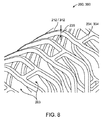
大腿動脈は、様々な力が、本装置を同時に、潰したり、捩ったり、伸ばしたり、縮めたりするような、血管埋込みに対する動的環境をもたらす。図12A乃至図12Bは、脚部の大腿動脈に作用するこれらの力の性質を示している。力の印加は、点荷重から分散荷重までの間、又はその組み合わせで変化するかもしれず、時間の関数として変化するかもしれない。最近の成果では、高結晶性PLLA製の生体再吸収性スキャフォールドが、血管へ恒久的で一定の半径方向外向きの力を生起することなく潰れ回復性を提供できることが示されている。恒久的で一定の半径方向外向きの力は、ニチノール自己拡張ステントに伴う後期臨床的問題の原因であるかもしれない。しかし、生体再吸収性スキャフォールドによる更なる挑戦は、それらスキャフォールドに時間の関数としての最適な破損耐性を持たせることである;即ち、様々な動的負荷環境の下での、それらスキャフォールドの疲労寿命又は生存性を向上させることである。 The femoral artery provides a dynamic environment for vascular implantation where various forces simultaneously collapse, twist, stretch, and contract the device. Figures 12A-12B illustrate the nature of these forces acting on the leg femoral artery. The application of force may vary from point load to distributed load, or a combination thereof, and may vary as a function of time. Recent results indicate that bioresorbable scaffolds made of highly crystalline PLLA can provide collapse recovery without creating a permanent, constant radial outward force on the blood vessels. Permanent and constant radial outward force may be responsible for late clinical problems associated with Nitinol self-expanding stents. However, a further challenge with bioresorbable scaffolds is to make them scaffolds with optimal failure resistance as a function of time; i.e., those scaffolds under various dynamic loading environments It is to improve the fatigue life or the viability.
血管スキャフォールドの破損耐性は、設計及び材料だけでなく製造プロセス及び展開パラメータにも依存する。したがって、スキャフォールドを均一に拡張し、展開することができるプロセス、設計、及び送達システムを有することが特に必要である。非均一な展開の結果として、スキャフォールドの種々のストラット及び冠部は、疲労寿命に有害な影響を及ぼす全く異なる力及び動きにさらされる可能性がある。 The fracture resistance of the vascular scaffold depends not only on the design and material, but also on the manufacturing process and deployment parameters. Therefore, it is particularly necessary to have a process, design, and delivery system that can uniformly expand and deploy the scaffold. As a result of non-uniform deployment, the various struts and crowns of the scaffold can be subjected to very different forces and movements that adversely affect fatigue life.
図7及び図9に図解するポリマースキャフォールドは、図1に示すようなポリ(L−ラクチド)(「PLLA」)チューブ101から形成される。チューブ101を形成するプロセスは、チューブ前駆体の押出し成形から始まる。ポリマーの溶融温度を超えて加熱されたPLLA樹脂原料は、続いて、237℃(華氏450度)の好ましい押出し温度で型を介して押出し成形される。プロセスのこのステップのさらなる詳細は、US2011/0066222(以後、’222公報とする)に記載されている。前駆体に対し、好ましくはブロー成形を用いて、慎重に制御した半径方向及び軸線方向の延伸加工が続いて行われる。この延伸プロセスを用いることにより、前駆体に端を発するスキャフォールドの所望の機械的特性が生み出される。望ましい特性には、例えば、結晶性、壁厚及び「真円度」、降伏強さ、スティフネス及び破壊靭性等の寸法的及び形態的な均一性が含まれる。結果として得られたチューブ101は、次に、レーザ切断プロセスによりスキャフォールドに形成される。 The polymer scaffold illustrated in FIGS. 7 and 9 is formed from a poly (L-lactide) (“PLLA”) tube 101 as shown in FIG. The process of forming the tube 101 begins with the extrusion of the tube precursor. The PLLA resin raw material heated above the melting temperature of the polymer is subsequently extruded through a mold at a preferred extrusion temperature of 237 ° C. (450 ° F.). Further details of this step of the process are described in US2011 / 0066222 (hereinafter referred to as the '222 publication). The precursor is followed by carefully controlled radial and axial stretching processes, preferably using blow molding. By using this drawing process, the desired mechanical properties of the scaffold originating from the precursor are produced. Desirable properties include, for example, dimensional and morphological uniformity such as crystallinity, wall thickness and “roundness”, yield strength, stiffness and fracture toughness. The resulting tube 101 is then formed into a scaffold by a laser cutting process.
前駆体の延伸は、前駆体の押出し成形中の圧力、速度、及び温度を含む慎重に制御されるパラメータを用いて行われる。延伸は、所望の結果が得られるように所定量分だけ軸線方向及び半径方向の両方向で発生するのが好ましい。PLLA前駆体は、PLLAガラス転移温度(即ち60〜70℃)を超えるが、溶融温度未満(165〜175℃)、好ましくは、約110〜120℃に加熱される。 The precursor stretching is performed using carefully controlled parameters including pressure, speed, and temperature during precursor extrusion. Stretching preferably occurs in both the axial and radial directions by a predetermined amount so that the desired result is obtained. The PLLA precursor is heated to a temperature above the PLLA glass transition temperature (ie 60-70 ° C) but below the melting temperature (165-175 ° C), preferably about 110-120 ° C.
好ましいブロー成形プロセスは、前駆体の長手方向軸線に沿った所定の長手方向速度で、前駆体を徐々に変形させる。チューブ変形プロセスは、以下でより詳細に説明するように、ポリマー鎖を半径方向及び/又は2軸方向に配向することを意図している。上記のように、再配置を生じる配向又は変形は、変形プロセス中に材料の結晶性及び結晶の種類の形成に影響を及ぼすよう、例えば、圧力、熱(即ち、温度)、変形率等の処理パラメータの厳密な選択に従って行われる。 A preferred blow molding process gradually deforms the precursor at a predetermined longitudinal velocity along the longitudinal axis of the precursor. The tube deformation process is intended to orient the polymer chains radially and / or biaxially, as will be described in more detail below. As described above, orientation or deformation that causes rearrangement may affect the crystallinity of the material and the formation of crystal types during the deformation process, eg, treatment of pressure, heat (ie, temperature), deformation rate, etc. This is done according to the exact selection of parameters.
代わりの実施の形態において、チューブは、ポリ(L−ラクチド−co−グリコリド)、ポリ(D−ラクチド−co−グリコリド)(「PLGA」)、ポリカプロラクトン(「PCL」)、他の適切な半結晶性コポリマー、又は、これらのポリマーの混合物からできていてもよい。ゴム強化材料も、ブロックコポリマー又は上記材料とポリカプロラクトン、ポリエチレングリコール、及びポリジオキサノン等の低Tg材料との組み合わせのポリマーブレンドを用いることによって達成されてもよい。代わりに、多層構造体を押出し成形するようにしてもよい。材料選択は、多くの末梢血管位置、特に四肢に近い位置、に関連する複雑な負荷環境を考慮するときに制限されることになる。 In alternative embodiments, the tube may be poly (L-lactide-co-glycolide), poly (D-lactide-co-glycolide) (“PLGA”), polycaprolactone (“PCL”), other suitable half It may be made of a crystalline copolymer or a mixture of these polymers. Rubber reinforcing materials may also be achieved by using a polymer blend of block copolymers or combinations of the above materials with low Tg materials such as polycaprolactone, polyethylene glycol, and polydioxanone. Alternatively, the multilayer structure may be extruded. Material selection will be limited when considering the complex loading environment associated with many peripheral vascular locations, particularly those close to the limbs.
ブロー成形は、第1に、チューブ前駆体(即ち、前駆体)を中空の円筒状部材つまり型の内部に位置決めすることを含む。型は、前駆体の外径又は表面の変形を型の内径に制限することによって前駆体の半径方向変形の程度を制御する。型内にある間、前駆体の温度は、変形を容易にするようPLLAのTgよりも高い。この温度は、「延伸温度」又は「プロセス温度」と称する処理パラメータである。延伸温度までの加熱は、ガスを延伸温度まで加熱し、加熱されたガスを、前駆体を収容する型の外面上へ吐出することによって達成できる。 Blow molding first involves positioning a tube precursor (ie, precursor) within a hollow cylindrical member or mold. The mold controls the extent of radial deformation of the precursor by limiting the outer diameter or surface deformation of the precursor to the inner diameter of the mold. While in the mold, the temperature of the precursor is higher than the TLA of PLLA to facilitate deformation. This temperature is a processing parameter called “stretching temperature” or “process temperature”. Heating to the stretching temperature can be accomplished by heating the gas to the stretching temperature and discharging the heated gas onto the outer surface of the mold containing the precursor.
型内にある間、前駆体の一端は封止される、又は閉鎖される。したがって、前駆体の他端へのガスの導入は、前駆体の外面と型の内面との間の領域において雰囲気圧(大気圧)に対する内部流体圧を増加させる。この内部流体圧は、「延伸圧力」又は「プロセス圧力」と称する処理パラメータである。延伸圧力を生じるために用いることのできるガスの例は、周囲空気(大気)、実質的に純粋な酸素、実質的に純粋な窒素、及び他の実質的に純粋な不活性ガスを含むがこれらに限定されるものではない。他のブロー成形プロセスパラメータと組み合わされて、延伸圧力は、前駆体が図1に示すチューブ101を生じるよう半径方向及び軸線方向に変形する速度に影響を及ぼす。ブロー成形は、前駆体の一端を引っ張ることを含んでもよい。別の処理パラメータである張力は、前駆体の他端を定置保持する間に、一端へ印加される。半径方向及び軸線方向に変形させられた前駆体は、次に、圧力を下げる、及び/又は、張力を下げる、前又は後のいずれかに、Tg超からTg未満まで冷却されてもよい。制御された温度での、又は制御された温度降下率での冷却は、チューブ101が半径方向延伸及び軸線方向延伸の後に適切な形状、大きさ、及び長さを確実に維持することに役立つ。Tm及びTg間の温度範囲にわたる徐冷は、結果としてアモルファス鎖配向を損ない、完成スキャフォールドにおける破壊靭性の低下の原因となるかもしれない。必ずしもではないが、変形した前駆体は、好ましくはチューブ延伸加工中に形成された鎖配向を維持するように、比較的冷たい気体又は液体中で、Tg未満の温度まで急速に冷却、つまり急冷する。次に、冷却後の変形した前駆体からはチューブ101が生成され、このチューブは、図4及び図7に示されるスキャフォールドを生成するよう切断されてもよい。US2012/0073733(代理人用整理番号104584.14)の図2A乃至図2Dは、ポリマーチューブの半径方向及び軸線方向の同時変形のための成形装置500を略示する。 While in the mold, one end of the precursor is sealed or closed. Thus, the introduction of gas to the other end of the precursor increases the internal fluid pressure relative to the atmospheric pressure (atmospheric pressure) in the region between the outer surface of the precursor and the inner surface of the mold. This internal fluid pressure is a processing parameter called “stretching pressure” or “process pressure”. Examples of gases that can be used to generate stretching pressure include ambient air (atmosphere), substantially pure oxygen, substantially pure nitrogen, and other substantially pure inert gases, but these It is not limited to. In combination with other blow molding process parameters, the stretching pressure affects the rate at which the precursor deforms radially and axially to produce the tube 101 shown in FIG. Blow molding may include pulling one end of the precursor. Another process parameter, tension, is applied to one end while holding the other end of the precursor stationary. The radially and axially deformed precursor may then be cooled from greater than Tg to less than Tg, either before or after reducing pressure and / or decreasing tension. Cooling at a controlled temperature, or at a controlled temperature drop rate, helps to ensure that the tube 101 maintains the proper shape, size, and length after radial and axial stretching. Slow cooling over the temperature range between Tm and Tg may result in loss of amorphous chain orientation and cause a reduction in fracture toughness in the finished scaffold. Although not necessarily, the deformed precursor is rapidly cooled, i.e. rapidly cooled, to a temperature below Tg, preferably in a relatively cool gas or liquid so as to maintain the chain orientation formed during the tube drawing process. . The tube 101 is then produced from the deformed precursor after cooling, and this tube may be cut to produce the scaffold shown in FIGS. FIGS. 2A-2D of US 2012/0073733 (Attorney Docket No. 104584.14) schematically illustrate a forming apparatus 500 for simultaneous radial and axial deformation of a polymer tube.
静的結晶化はポリマー溶融物から生じることができるが、これは、単にポリマー変形により生じる結晶化とは区別すべきである。一般に、静的結晶化は、ポリマーのTgとTm間の温度で半結晶ポリマーの状態で生じる傾向がある。この範囲での静的結晶化の速度は温度によって異なる。Tg近傍では、核形成速度は比較的高く、静的結晶成長速度は比較的低;それ故ポリマーはこれらの温度において小さい結晶を形成する傾向がある。Tm近傍では、核形成速度は比較的低く、静的結晶成長速度は比較的高い;それ故ポリマーはこれらの温度において大きい結晶を形成する。 Static crystallization can arise from the polymer melt, but this should be distinguished from crystallization caused solely by polymer deformation. In general, static crystallization tends to occur in the semicrystalline polymer state at temperatures between the Tg and Tm of the polymer. The rate of static crystallization in this range varies with temperature. Near Tg, the nucleation rate is relatively high and the static crystal growth rate is relatively low; therefore, the polymer tends to form small crystals at these temperatures. Near Tm, the nucleation rate is relatively low and the static crystal growth rate is relatively high; therefore, the polymer forms large crystals at these temperatures.
先に指摘したように、結晶化もポリマーの変形により生じる。変形によりポリマー鎖は長く延伸され、場合によっては、結果として特定の方向に概して配向される繊維状結晶を生じる。PLLA製のポリマーチューブを、Tgを超える特定の延伸温度でブロー成形によって変形することは、結果として、変形により誘発される結晶化と温度により誘発される結晶化との組み合わせを生じる。 As pointed out above, crystallization also occurs due to deformation of the polymer. Deformation causes the polymer chains to be elongated longer, and in some cases results in fibrous crystals that are generally oriented in a particular direction. Deformation of a PLLA polymer tube by blow molding at a specific stretching temperature above Tg results in a combination of deformation-induced crystallization and temperature-induced crystallization.
上で指摘したように、ポリマーの変形する能力は、ブロー成形温度(「延伸温度」)によって決まるとともに、印加される内圧(「拡張圧力」)及び張力によっても決まる。温度がTgを超えて上昇するにつれて、分子配向は、印加される応力によってより容易に誘発される。また、温度がTmに近づくにつれて、静的結晶成長速度は上昇し、静的核形成速度は低下する。したがって、上記のブロー成形プロセスが、結晶化パーセンテージ、結晶サイズ、結晶分布の均一性、及び好ましい分子又は結晶配向に同時に影響を及ぼすすべての処理パラメータの複雑な相互作用に関わることも正しく理解されよう。先に言及したように、好ましい実施の形態においては、PLLAチューブは、すべてPLLAでできていた。最大約20%、及び、より狭い約5%から約15%の初期(ブロー成形前)結晶化パーセンテージを有するPLLA前駆体のためのブロー成形プロセスパラメータに対する好ましいレベルを、以下に示す。出願人は、以下に示すブロー成形プロセスパラメータレベルが、結果として、50%未満、及び、より狭い約30%から約40%の結晶化パーセンテージを有する変形PLLAチューブを生じると考えている。延伸後、チューブ101は上昇された温度に長期間さらされてもよい。一の実施の形態において、PLLAチューブ101は、チューブをレーザ切断してスキャフォールドを形成する前に、約40〜50℃の間、又は約47℃の温度にさらされる。このステップは、延伸されたチューブを急冷した後に行う。プロセス内に含むことのできる、後続の、長期にわたる上昇温度への曝露は、通常のアニールプロセスよりもはるかにゆっくりとした変形前駆体における内部応力の緩和を誘導することを目的としている。そのプロセスは、「冷間結晶化プロセス」として考えてもよい。 As pointed out above, the ability of a polymer to deform depends not only on the blow molding temperature (“stretching temperature”) but also on the applied internal pressure (“expansion pressure”) and tension. As the temperature rises above Tg, molecular orientation is more easily induced by the applied stress. Also, as the temperature approaches Tm, the static crystal growth rate increases and the static nucleation rate decreases. Thus, it will also be appreciated that the blow molding process described above involves a complex interaction of all processing parameters that simultaneously affect the crystallization percentage, crystal size, crystal distribution uniformity, and preferred molecular or crystal orientation. . As mentioned above, in the preferred embodiment, the PLLA tubes were all made of PLLA. Preferred levels for blow molding process parameters for PLLA precursors having initial (pre-blow molding) crystallization percentages of up to about 20% and narrower about 5% to about 15% are shown below. Applicants believe that the blow molding process parameter levels shown below result in deformed PLLA tubes having less than 50% and a narrower crystallization percentage of about 30% to about 40%. After stretching, the tube 101 may be exposed to elevated temperatures for extended periods. In one embodiment, PLLA tube 101 is exposed to a temperature between about 40-50 ° C. or about 47 ° C. before laser cutting the tube to form a scaffold. This step is performed after quenching the stretched tube. Subsequent, prolonged exposure to elevated temperatures that can be included in the process is aimed at inducing relaxation of internal stresses in the deformed precursor much slower than the normal annealing process. The process may be considered as a “cold crystallization process”.
以下は、末梢血管に埋め込まれるポリマースキャフォールドの作成に用いる最良の又は改良されたチューブ形成を判定するために行われた研究の検討である。この研究は、主に、2軸方向に延伸されたチューブのどのタイプが、スキャフォールドの他の機械的特性に悪影響を及ぼすことなく、末梢血管に埋め込まれるスキャフォールドのためのストラット破断及び亀裂伝播の速度又は数を減少させる可能性があるかを判定することに向けられた。事前のスキャフォールドは、400〜450%(RE)と20〜45%(AE)との間の2軸延伸を有するチューブから形成された。 The following is a review of studies conducted to determine the best or improved tube formation used to create polymer scaffolds that are implanted in peripheral vessels. This study mainly focuses on strut rupture and crack propagation for scaffolds embedded in peripheral vessels without any type of biaxially stretched tube adversely affecting the other mechanical properties of the scaffold. Directed to determine if there is a possibility to reduce the speed or number of The pre-scaffold was formed from a tube with a biaxial stretch between 400-450% (RE) and 20-45% (AE).
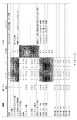
3つの異なる半径方向及び軸線方向延伸ペアによる2軸延伸されるPLLA前駆体チューブに用いられる処理パラメータを表1に要約する。

400/200、200/200、及び400/45の2軸延伸のケースに加えて、研究では、480/45の2軸延伸チューブを考慮した。400/45のケースは、スキャフォールドのためのひとつの既存のチューブ形成を表す制御のケースである。 In addition to the 400/200, 200/200, and 400/45 biaxially stretched cases, the study considered 480/45 biaxially stretched tubes. The 400/45 case is a control case that represents one existing tube formation for the scaffold.
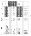
表1によるチューブ形成後、チューブ及びチューブから形成されるスキャフォールドの両方に対して、異なる2軸延伸の関数として変化する半径方向強度及び破損時における伸び等の機械的特性を評価するよう種々の試験を行った。行った試験を表2に要約し、以下で詳細に説明する:
各試験に対し、統計を取るために3〜5個のサンプルを用いた。試験の結果を、図2乃至図6及び以下に要約する。 For each test, 3-5 samples were used for statistics. The test results are summarized in FIGS. 2-6 and below.
V79スキャフォールド(図7、図10B、及び図11Bで説明される)は、壁厚0.28mm(0.011インチ)及び外径7mmである。イヌの骨サンプル(イヌの骨状サンプル)が作成されたチューブの壁厚及び外径はスキャフォールドと同じであった。スキャフォールドは、Abbott Vascular, Incから入手可能なFoxSV(商標)0.018PTAカテーテルにスキャフォールドをクリンプすることにより用意した。外径7.0スキャフォールドを、米国特許出願13/644,347(代理人用整理番号62571.675)に記載されているプロセスに従って2.03mmの外径にクリンプした。クリンプしたスキャフォールドを電子線殺菌し、バルーンを、PTAカテーテルに対する通常のバルーン膨張プロトコル(方式)に従って外径5.4mmまで膨張させた。試験において、スキャフォールドは、内径5.4(スキャフォールドの外径)のポリカーボネートブロック内へと展開される。軸線方向疲労試験において、スキャフォールドは、内径5.0mmのチューブへと展開された。 The V79 scaffold (described in FIGS. 7, 10B, and 11B) has a wall thickness of 0.28 mm (0.011 inches) and an outer diameter of 7 mm. The wall thickness and outer diameter of the tube from which the dog bone sample (dog bone-like sample) was made were the same as the scaffold. The scaffold was prepared by crimping the scaffold onto a FoxSV ™ 0.018 PTA catheter available from Abbott Vassular, Inc. The outer diameter 7.0 scaffold was crimped to an outer diameter of 2.03 mm according to the process described in US patent application 13 / 644,347 (Attorney Docket No. 62571.675). The crimped scaffold was electron sterilized and the balloon was inflated to an outer diameter of 5.4 mm according to the normal balloon inflation protocol for a PTA catheter. In the test, the scaffold is deployed into a polycarbonate block with an inner diameter of 5.4 (outer diameter of the scaffold). In the axial fatigue test, the scaffold was developed into a tube with an inner diameter of 5.0 mm.
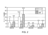
試験Aは、大腿動脈に埋め込まれ、通常の歩行により生じるこれらの繰返し負荷をかけられる場合の末梢血管スキャフォールドへの軸線方向負荷環境をシミュレートする。この種類の負荷が、スキャフォールドストラットの破損に対する大きな要因であることが判明した。このように、これは、末梢血管スキャフォールドの適合性を評価する良好なベンチマークであると考えられる。約100万回の軸線方向負荷サイクルは、平均的な人間による1年間の歩行を表すと推定される。好ましい実施の形態によるスキャフォールドに対して、最も関心のある期間は6ヶ月であり、この期間は、6日間にわたる加速した周期的軸線方向負荷(6日間の経過にわたる500,000サイクル)を行うことによって推定できる。6日間の負荷期間を通して、スキャフォールドは、温度37℃(体温)の水中に浸漬される。試験Aによる平均及び標準偏差値(n=5)を、図2に示す。 Test A simulates an axial loading environment on the peripheral vessel scaffold when implanted in the femoral artery and subjected to these repeated loads caused by normal walking. This type of load has been found to be a major factor for scaffold strut failure. Thus, this is considered a good benchmark for assessing the suitability of peripheral vascular scaffolds. Approximately 1 million axial duty cycles are estimated to represent an average human walk for one year. For the scaffold according to the preferred embodiment, the period of most interest is 6 months, this period being subjected to accelerated periodic axial loading over 6 days (500,000 cycles over 6 days) Can be estimated. Throughout the 6 day loading period, the scaffold is immersed in water at a temperature of 37 ° C. (body temperature). The mean and standard deviation values (n = 5) from test A are shown in FIG.
試験B及びC(材料試験)に対し、リング状及びストリップ(帯)状のイヌの骨サンプルは、レーザを用いて2軸延伸チューブから切り取られ、次いで、(スキャフォールドが埋め込まれる前には殺菌されるように)電子線殺菌された。イヌの骨が、例えば、軸線方向疲労負荷及び(以下で検討するような)水和作用による変化を受けた場合のスキャフォールドの挙動をより良く理解するために、2軸延伸材料の軸線方向及び周方向特性を測定するように選択された。試験B及びCの両方に対して、破損時における伸びは、3つのケースに対し室温で測定された:37℃の水中に6日間浸漬されたイヌの骨、37℃の水中に2時間浸漬されたイヌの骨、及び水中に浸漬されていないイヌの骨。 For tests B and C (material test), ring and strip dog bone samples were cut from a biaxially stretched tube using a laser and then sterilized (before the scaffold was implanted) ) As electron beam sterilized. To better understand the behavior of the scaffold when the dog bone is subjected to changes due to, for example, axial fatigue loading and hydration (as discussed below), the axial direction of the biaxially stretched material and Selected to measure circumferential characteristics. For both tests B and C, the elongation at break was measured at room temperature for three cases: dog bone immersed in 37 ° C. water for 6 days, immersed in 37 ° C. water for 2 hours. Dog bones and dog bones not immersed in water.
破損時における半径方向又は周方向の伸び(試験B)に対して、リングを、壁厚0.011及び外径7のチューブから切り取り、狭窄部(狭く形成した部分)を、周方向の破損時における伸びを測定するよう(レーザを用いて)形成した。リングに、50mm/分の速度で均一の半径方向外側の負荷をかけ、破損するまで周方向ひずみを測定した。試験Bによる平均及び標準偏差値(n=5)を図3に示す。 The ring is cut from a tube having a wall thickness of 0.011 and an outer diameter of 7 for the radial or circumferential elongation at the time of breakage (test B), and the narrowed portion (the narrowly formed portion) is broken in the circumferential direction. It was formed to measure the elongation at (using a laser). A uniform radial outer load was applied to the ring at a speed of 50 mm / min, and circumferential strain was measured until it failed. The average and standard deviation values (n = 5) from test B are shown in FIG.
破損時における軸線方向の伸び試験(試験C)に対して、ストリップ(細くて薄い板状の部材)を(レーザを用いて)チューブから切り取り、破損時における軸線方向の伸びを測定するよう、狭窄部をそのストリップに形成した。ストリップは、50mm/分の速度で軸線方向の引張荷重をかけ、破損するまで軸線方向ひずみを測定した。試験Cによる平均及び標準偏差値(n=5)を図4に示す。 In contrast to the axial elongation test at break (Test C), a strip (thin and thin plate-like member) is cut from the tube (using a laser) and narrowed to measure the axial elongation at failure. A part was formed in the strip. The strip was subjected to an axial tensile load at a rate of 50 mm / min and the axial strain was measured until it failed. The average and standard deviation values (n = 5) from test C are shown in FIG.
試験Dは、次の2つのケースに対するスキャフォールドの半径方向強度及びスティフネスを推定する:軸線方向疲労試験(試験A)前後のスキャフォールド。試験Dは、MSI RX550 Radial Force Testerを用いて、STM2076919に基づく試験方法/手順に従って、均一な半径方向内向きの力をスキャフォールドに印加する。それ以前に試験Aを受けていないスキャフォールドは、半径方向強度に対して試験した。それ以前に軸線方向疲労負荷にかけたスキャフォールドも、軸線方向における繰り返し疲労負荷後の半径方向強度及びスティフネスの変化を評価するよう試験した。500,000サイクルに対して、1Hzの周波数で、試験Aの期間は6日間であり、したがって、37℃の水中に浸漬した後の半径方向強度の変化も、半径方向強度の軸線方向疲労後評価のこの同じ試験により観察された。 Test D estimates the radial strength and stiffness of the scaffold for the following two cases: the scaffold before and after the axial fatigue test (Test A). Test D uses a MSI RX550 Radial Force Tester to apply a uniform radial inward force to the scaffold according to a test method / procedure based on STM2076919. Scaffolds that had not previously undergone test A were tested for radial strength. Scaffolds previously subjected to axial fatigue loading were also tested to assess changes in radial strength and stiffness after repeated fatigue loading in the axial direction. For 500,000 cycles, at a frequency of 1 Hz, the duration of test A is 6 days, so the change in radial strength after immersion in 37 ° C. water is also evaluated after axial fatigue of radial strength. Of this same test.
以前に試験Aにかけられたスキャフォールドは、試験される前に37℃の水中に2分間、再度浸漬された。図5を参照すると、力とは「正規化された」力を指し、スキャフォールドの長さに関して正規化された力を意味する。したがって、単位は、単位長さ当たりの力、即ち、図5の場合では、N/mmである。この試験に対して用いられる軸線方向疲労後のスキャフォールドは、実質的に無傷のリングを有するスキャフォールドであった。疲労試験中、水分がスキャフォールドを可塑化し、それによって、特に材料のアモルファス相の形態学的変化を許容し、結果として、半径方向強度及びスティフネスは、発生するスキャフォールド破壊にもかかわらず増加する。 Scaffolds previously subjected to test A were re-immersed in 37 ° C. water for 2 minutes before being tested. Referring to FIG. 5, force refers to a “normalized” force and means a force that is normalized with respect to the length of the scaffold. Therefore, the unit is the force per unit length, ie, N / mm in the case of FIG. The scaffold after axial fatigue used for this test was a scaffold with a substantially intact ring. During fatigue testing, moisture plasticizes the scaffold, thereby allowing morphological changes in the amorphous phase of the material, in particular, resulting in increased radial strength and stiffness despite the scaffold failure occurring. .
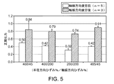
試験Eは、5.4mmの延伸直径からのリコイルを測定する。24時間(n=3)にわたる400/200及び400/45の2軸延伸スキャフォールドのリコイル間の比較を、図6に示す。下の表3は、1/2時間(急性リコイル)、1時間、1日、及び7日後のリコイルに対する平均及び標準偏差を示している。これらのリコイル測定のためのスキャフォールドは37℃の水中に浸漬される。 Test E measures recoil from a stretched diameter of 5.4 mm. A comparison between the recoil of 400/200 and 400/45 biaxially stretched scaffolds over 24 hours (n = 3) is shown in FIG. Table 3 below shows the mean and standard deviations for recoil after 1/2 hour (acute recoil), 1 hour, 1 day, and 7 days. The scaffolds for these recoil measurements are immersed in 37 ° C. water.
試験A(軸線方向疲労)を受けたスキャフォールドのストラット及びリンクにおける破損の数を示す図2は、400/200又は200/200の2軸延伸がスキャフォールドにおける最少不具合を生じることを示している。さらに、試験は、破損した連結要素がまったく無いにもかかわらず、400/200及び200/200スキャフォールドに対して、400/45及び480/45のケースよりも統計学上有意な低い数の不連続ストラットを示している。 FIG. 2, which shows the number of fractures in the struts and links of the scaffold subjected to test A (axial fatigue), shows that 400/200 or 200/200 biaxial stretching results in minimal failure in the scaffold. . In addition, the test shows that for 400/200 and 200/200 scaffolds, there is a statistically significant lower number of failures than the 400/45 and 480/45 cases, even though there are no broken connecting elements. A continuous strut is shown.
この結果は、ストラットによって形成されるリングを軸線方向で相互に連結するリンクの破損がまったく無いにもかかわらず、400/200及び200/200のスキャフォールドに対して、破損したストラットの総数は、より多くのリンクが破損した場合よりも少なかったため、よりバランスのとれたRE及びAEがリングの完全性にとって有益となり得ることを示唆している。軸線方向疲労に応じて、よりバランスのとれた2軸延伸を選択するための推論は以下のとおりである。リンクが破損すれば、リングへの荷重経路が切られるため、リング要素にかかる全応力は少ないと推測するかもしれない。そして、より多くのリンクが破損すれば、最終的に破損するストラットはより少なくなるはずと結論付けるであろう。しかし、図2は、ストラットへの荷重経路が無傷である、即ち何のリンクも破損していないにもかかわらず、よりバランスのとれたRE及びAE、例えば、400/200又は200/200がより良好な結果を生じることを示唆している。 This result shows that for 400/200 and 200/200 scaffolds, the total number of broken struts, despite the fact that there is no damage to the links that interconnect the rings formed by the struts in the axial direction, This suggests that a more balanced RE and AE may be beneficial for ring integrity, since less than if more links were broken. The reasoning for choosing a more balanced biaxial stretching depending on axial fatigue is as follows. If the link breaks, it may be assumed that the total stress on the ring element is low because the load path to the ring is cut. You will conclude that if more links break, fewer struts will eventually break. However, FIG. 2 shows that a more balanced RE and AE, such as 400/200 or 200/200, is better even though the load path to the strut is intact, ie no link is broken. Suggests good results.
図5は、軸線方向疲労前後のスキャフォールド(試験D)に対する正規化された半径方向強度(力/長さ)を示している。結果は、実質的に無傷のリングを有するスキャフォールドに対して、半径方向力が、軸線方向疲労前のスキャフォールドよりも軸線方向疲労後のスキャフォールドの方が高いことを示している。いずれか特定の理論に結び付けられることを望むことなく、発明者は、モフォロジへの影響が少なくとも部分的に水分吸収によるものであると考えている。材料は、それが水和する場合に可塑化し、増加した鎖運動性につながり、結果として、アモルファスと結晶方位に影響を及ぼすアモルファス−結晶相の界面との両方における結晶化度及び鎖転位等の形態学的変化を生じる。これらの変化は、スキャフォールドの半径方向強度を向上させることができる。水和プロセス及び結果としての形態学的変化はまた、周方向に配向される比較的高いスキャフォールド(例えば、400/45)を半径方向荷重状態で靭性を低くさせるが、RE対AEのより少ない比(例えば、400/200)に対する2軸チューブの靭性の変化も少ないと考えられる。破損時における伸びは、ポリマーにとって良好な靭性の指標である。実際に、スキャフォールドの骨格として用いるのに適したポリマーに関して、多くの場合、破損時におけるより高い伸びもまた靭性の増加を示している。 FIG. 5 shows the normalized radial strength (force / length) for the scaffold before and after axial fatigue (Test D). The results show that for a scaffold with a substantially intact ring, the radial force is higher for the scaffold after axial fatigue than for the scaffold before axial fatigue. Without wishing to be tied to any particular theory, the inventor believes that the effect on morphology is at least partly due to moisture absorption. The material plasticizes when it hydrates, leading to increased chain mobility, resulting in crystallinity and chain dislocations both at the amorphous and at the amorphous-crystalline phase interface that affects crystal orientation. Causes morphological changes. These changes can improve the radial strength of the scaffold. The hydration process and the resulting morphological changes also cause a relatively high scaffold (eg 400/45) oriented in the circumferential direction to be less tough in radial loading conditions, but less RE vs. AE It is considered that the change in toughness of the biaxial tube with respect to the ratio (for example, 400/200) is small. Elongation at break is a good toughness indicator for polymers. Indeed, for polymers suitable for use as scaffold scaffolds, in many cases, higher elongation at failure also indicates increased toughness.
注目すべきことに、図5において、400/45及び480/45の2軸延伸を有するスキャフォールドの半径方向強度と、400/200の2軸延伸を有するスキャフォールドの半径方向強度との間にほとんど差が無い。そうではなく、400/45における結晶構造/ポリマー鎖の配向が400/200よりもはるかに多いため、相違はより大きいだろうと、予想されていたであろう。軸疲労前後の両方に対して、400/200の2軸延伸を有するスキャフォールドの半径方向強度は、400/45及び480/45の2軸延伸を有するスキャフォールドにおけるものと略同じである。図5は、よりバランスのとれた半径方向及び軸線方向延伸が、以前であれば結論付けられたかもしれないような、半径方向強度(又はスティフネス)への悪影響を有していないことを示している。 Of note, in FIG. 5, between the radial strength of the scaffold with biaxial stretching of 400/45 and 480/45 and the radial strength of the scaffold with biaxial stretching of 400/200. There is almost no difference. Instead, it would have been expected that the difference would be greater because the crystal structure / polymer chain orientation at 400/45 was much more than 400/200. For both before and after axial fatigue, the radial strength of the scaffold with 400/200 biaxial stretching is approximately the same as in the scaffold with 400/45 and 480/45 biaxial stretching. FIG. 5 shows that a more balanced radial and axial stretch does not have an adverse effect on radial strength (or stiffness) as might have been previously concluded. Yes.
試験E(図6及び表3)では、異なる2軸延伸に対するスキャフォールドのリコイルが測定された。結果は、よりバランスのとれた2軸延伸が7日後の低いリコイルとリコイルの早い段階での収束の両方を生じることができることを示している。
表3が400/200に対して示すように、早い段階での収束と1時間後の単調に減少するリコイルとの両方がある。1日後の動向(400/45との比較)を図6に示す。したがって、リコイルは、よりバランスのとれた2軸延伸に対して、より少なく、早く収束する。 As Table 3 shows for 400/200, there is both an early convergence and a monotonically decreasing recoil after 1 hour. The trend after one day (comparison with 400/45) is shown in FIG. Thus, recoils are less and converge faster with more balanced biaxial stretching.
先に示した試験B及びCはイヌの骨を用いる材料試験である。図4は、乾燥状態、2時間浸漬、及び6日浸漬のイヌの骨のサンプルに対する破損時における半径方向又は周方向の伸びを示している。ここでは、破損時における半径方向伸びに全体的な低下がある。 Tests B and C shown above are material tests using canine bone. FIG. 4 shows radial or circumferential elongation at break for a sample of canine bone that was dry, 2 hours immersed, and 6 days immersed. Here, there is an overall decrease in radial elongation upon failure.
図3は、乾燥状態、2時間浸漬、及び6日間浸漬のイヌの骨のサンプルに対する破損時における軸線方向伸びを示している。乾燥状態及び2時間の浸漬時間に対して、破損時における伸びは、それぞれのケースに対して、同じままであるか、僅かに減少するかのいずれかである。乾燥状態、2時間、及び6日間の材料の(弾性)係数/スティフネスに対する同様の測定は、長時間、材料が水中に浸漬されると減少することを示している。 FIG. 3 shows the axial elongation at break for a sample of canine bone that was dry, immersed for 2 hours, and immersed for 6 days. For dry conditions and 2 hours of immersion time, the elongation at break either remains the same for each case or decreases slightly. Similar measurements on the (elastic) modulus / stiffness of the material in the dry state, 2 hours, and 6 days indicate that the material decreases when immersed in water for a long time.
しかし、37℃の水中に6日間浸漬された後、破損時における伸びは、400/45及び480/45のケースに対して劇的に低下する。係数及び破損時における伸びの両方が、水和作用が増加するとともに低下することを見出したため、材料の靭性(又は材料を破壊するために必要なひずみエネルギー)は、水和し、バランス度が低い2軸延伸ケースに対して著しく低下する。400/45及び480/45のイヌの骨を試験する場合、軸線方向におけるそれらの最終的なひずみは、劇的に低下する。 However, after being immersed in 37 ° C. water for 6 days, the elongation at break is dramatically reduced for the 400/45 and 480/45 cases. We found that both modulus and elongation at failure decrease with increasing hydration, so the toughness of the material (or the strain energy required to break the material) is hydrated and poorly balanced This is significantly lower than the biaxially stretched case. When testing 400/45 and 480/45 dog bones, their ultimate strain in the axial direction is dramatically reduced.
以前に検討したように、出願人は、この結果を、水和/可塑化効果によるポリマーの材料の形態学的変化によって説明できると考えている。200%の軸線方向ひずみにより、水和後の方向の変化は、45%の軸線方向ひずみケースと比較して劇的に低い。400/45ケースにおいては、ほとんどのポリマー鎖は、略周方向の配向を有しており、これは、軸線方向結合力が分子間力によって主に提供されることを意味する。材料を相互に保持するこれらの分子間力は、(材料が湿潤状態で可塑化され、高温で埋め込まれる結果として)Tgが低下するにつれて、実質的に弱まり、それによって、エントロピーとしてより多くの鎖運動を可能にし、自由体積が増加する。400/200のケースにおいて、より大きい軸線方向結合力が、ポリマー鎖の骨格によって提供される。このモフォロジは、鎖の細密充填、ひずみが誘導する追加の結晶性、及び結晶構造の軸線方向配向によって、物理的な架橋結合の可能性を生み出す。濡れた場合、鎖は、初期水和プロセス中にそれらの配向のうちのいくつかを失うかもしれないが、鎖が材料降伏前に長距離を滑る必要があるので、降伏ひずみはそれ程の影響を受けない。 As previously discussed, Applicants believe that this result can be explained by the morphological change of the polymer material due to the hydration / plasticization effect. With 200% axial strain, the change in direction after hydration is dramatically lower compared to the 45% axial strain case. In the 400/45 case, most polymer chains have a generally circumferential orientation, which means that axial binding forces are mainly provided by intermolecular forces. These intermolecular forces that hold the materials together substantially weaken as Tg decreases (as a result of the materials being plasticized in the wet state and embedded at high temperatures), thereby increasing the amount of entropy as chains Allows movement and increases free volume. In the 400/200 case, a greater axial binding force is provided by the polymer chain backbone. This morphology creates the possibility of physical cross-linking through close packing of chains, additional crystallinity induced by strain, and the axial orientation of the crystal structure. When wet, the chains may lose some of their orientation during the initial hydration process, but the yield strain is less affected because the chains need to slide long distances before material yield. I do not receive it.
軸線方向において、主要な結合力は、ポリマー鎖骨格によって提供される。ポリマー鎖骨格は、軸線方向でより多く配向され、鎖の細密充填、ひずみが誘導する追加の結晶性、及び結晶構造の軸線方向配向によって、物理的な架橋結合の可能性を生み出す。濡れた場合、軸線方向における配向の喪失は、結果として、軸線方向における降伏ひずみ及び係数の低下を招く。 In the axial direction, the main binding force is provided by the polymer chain backbone. The polymer chain backbone is more orientated in the axial direction, creating the possibility of physical cross-linking through close packing of chains, additional crystallinity induced by strain, and the axial orientation of the crystal structure. When wet, the loss of orientation in the axial direction results in a decrease in yield strain and modulus in the axial direction.
材料試験からの係数データは、半径方向及び軸線方向成分を示している。スキャフォールドの頂部及び冠部(半径方向負荷の間に高い応力領域)は、ポリマー鎖のための半径方向及び軸線方向の両方向成分がスティフネス挙動に寄与できる特定の角度で配向される。報告されたスティフネスは、周方向に圧縮されたスキャフォールドに関して試験された。材料の軸線方向疲労試験において、スキャフォールドは、軸線方向に負荷がかけられる。それは、長手方向軸線に沿ったリンクを介するリングへの荷重経路を提供する。半径方向圧縮ケースに対して、軸線方向延伸は、軸線方向疲労結果における半径方向延伸よりも、結果においてより重要な役割を果たすかもしれない。 The coefficient data from the material test shows the radial and axial components. The top and crown of the scaffold (high stress region during radial loading) are oriented at a specific angle that allows both radial and axial components for the polymer chain to contribute to the stiffness behavior. The reported stiffness was tested on a circumferentially compressed scaffold. In the axial fatigue test of the material, the scaffold is loaded in the axial direction. It provides a load path to the ring via links along the longitudinal axis. For radial compression cases, axial stretching may play a more important role in the results than radial stretching in axial fatigue results.
上記の試験結果は、よりバランスのとれた2軸延伸、例えば、400/200又は200/200が、半径方向及び軸線方向の両方のスキャフォールドの破損耐性に恩恵をもたらす傾向があり、リコイルを低減し、及び/又はリコイルを短い時間で定常状態に収束させ、そして、末梢血管に埋め込まれた後の材料の強度特性の劇的な変化が少ないことを示している。 The above test results show that more balanced biaxial stretching, for example 400/200 or 200/200, tends to benefit both radial and axial scaffold failure resistance, reducing recoil And / or show that the recoil converges to a steady state in a short time and there are few dramatic changes in the strength properties of the material after it has been implanted in the peripheral blood vessel.
この試験に基づいて、バランスのとれた2軸延伸の最適な組み合わせを選択することによって、末梢血管において用いるための末梢血管スキャフォールドの適合性が向上することが結論付けられた。表4は、480/45、400/45、400/200、及び200/200の2軸延伸ケースの試験からの結果を要約し、破損時における半径方向及び軸線方向の伸びを比較している。
破損時における軸線方向対半径方向の伸びの比は、全体のゆがみの度合い(形状の変化)の大きさである。高い比は、軸線方向及び半径方向負荷の間のより大きなゆがみを意味する。 The ratio of axial to radial elongation at the time of failure is the magnitude of the overall distortion (shape change). A high ratio means greater distortion between axial and radial loads.
この基準を用いて、400/200のケースが、末梢血管スキャフォールド環境に対する最良の総合的な機械的特性を提供したと考えられる。試験データに基づいて、改良された末梢血管スキャフォールド製品を提供できるチューブの材料又は処理特性に関して、以下の結論に到達した。実施の形態において、2軸延伸は、半径方向において約400〜500から、そして、軸線方向において約150〜200からの範囲に及んでいてもよい。実施の形態において、RE/AEの比は約2と1の間、2.5対1、3対1、及び4対1であってもよい。 Using this criterion, it is believed that the 400/200 case provided the best overall mechanical properties for the peripheral vascular scaffold environment. Based on the test data, the following conclusions were reached regarding the material or processing characteristics of the tube that can provide an improved peripheral vascular scaffold product. In embodiments, biaxial stretching may range from about 400 to 500 in the radial direction and from about 150 to 200 in the axial direction. In embodiments, the ratio of RE / AE may be between about 2 and 1, 2.5 to 1, 3 to 1, and 4 to 1.
以下は、開示に従って構成されるチューブからできるスキャフォールドの好ましい実施の形態の説明である。 The following is a description of a preferred embodiment of a scaffold made from a tube constructed in accordance with the disclosure.
図1の、強化され、靱性を増した円筒形ポリマーチューブは、スキャフォールド構造に形成される。一の実施の形態において、その構造は、図7に示すようなパターン200を形成する複数のストラット230及びリンク234を有している(パターン200は平面図又は平坦化図で示されている)。ここで図2は、クリンプ前と、スキャフォールドがバルーン膨張によって血管内で塑性的又は不可逆的にクリンプ状態から展開状態まで変形された後とのスキャフォールドのパターンに関するものである。したがって、図7のパターン200は、軸線A−Aがスキャフォールドの中心軸線又は長手方向軸線と平行であるような、(図8の3次元空間で部分的に示すような)管状スキャフォールド構造を表している。図8は、クリンプ前又は展開後の状態のスキャフォールドを示す。図8から分かるように、スキャフォールドは、略管状の本体を画成するストラットとリンクとのフレーム構造を有する。図1の変形される円筒形チューブは、レーザ切断装置、好ましくは、ヘリウムガスを切断時の冷却剤として使用するピコ秒緑色光レーザによって、図7〜図8で説明する、ストラット及びリンクでできたこのオープンフレーム構造に形成されてもよい。
The reinforced, toughened cylindrical polymer tube of FIG. 1 is formed into a scaffold structure. In one embodiment, the structure includes a plurality of
図7を参照すると、パターン200は、ストラット230によって形成される長手方向に離間したリング212を含んでいる。ストラットによって形成される8つの冠部又は頂部がある。リング212は、それぞれが軸線A−Aと平行に延在する2つ以下のリンク234によって隣接リングに接続される。スキャフォールドパターン(パターン200)のこの第1の実施の形態において、2つのリンク234が、2つの隣接するリングのそれぞれに内部リング212を接続する。内部リング212とは、図7において、その左右に一つずつのリングを有するリングである。このように、リング212bは、2つのリンク234によってリング212cに、そして、2つのリンク234によってリング212aに接続される。端部リング(不図示)は、ただ1つの別のリングに接続される端部リングである。
With reference to FIG. 7, the
リング212は、冠部207、209、及び210に接続されるストラット230によって形成される。リンク234は、冠部209(W字形冠部)及び冠部210(Y字形冠部)でストラット230に接合される。冠部207(自由冠部)はそれに接続されるリンク234を持っていない。冠部中央から一定の角度で冠部207、209、及び210から延在するストラット230、すなわち、リング212は、パターン200の正弦波形とは対照的に、略ジグザグ形状であるのが好ましい。このように、この実施の形態において、隣接する冠部207と209/210間の長手方向距離であるリング212の高さは、冠部において、冠部角度θで接続する2つのストラット230の長さから導出されてもよい。実施の形態によっては、異なる冠部同士の角度θは、リンク234が自由冠部又は未接続冠部、W字形冠部又はY字形冠部、に接続されているかどうかによって変わる。
リング212のジグザグ変化は主に、スキャフォールドの周で(すなわち、図7の方向B−Bに沿って)生じる。ストラット212の重心軸線は主に、スキャフォールドの長手方向軸線から略同じ半径方向距離にある。リングを形成するストラット間の実質的にすべての相対運動も、クリンプ及び展開中に、半径方向ではなく軸線方向に生じるのが理想である。より詳細に以下説明するが、ポリマースキャフォールドは、位置合わせ不良及び/又は印加される不均一な半径方向負荷により、このようには変形しないことがある。
The zigzag change in
リング212は、クリンプ中に、より小さい直径につぶすことができ、血管内での展開中により大きな直径に拡張できる。開示の一の態様によれば、クリンプ前直径(例えば、スキャフォールドが切り出される軸線方向及び半径方向に拡張(延伸)したチューブの直径)は常に、送達バルーンの膨張時に生成できる、すなわち可能な最大に拡張されたスキャフォールドの直径以上である。
The
スキャフォールド構造の第2の実施の形態のパターンは図9に示すパターン300である。パターン200と同様に、パターン300は、ストラット330によって形成される長手方向に離間したリング312を含んでいる。各リング312のストラットによって形成される12の頂部又は冠部がある。リング312は、それぞれが軸線A−Aと平行に延在する2つ以下のリンク334によって隣接リングに接続される。上記の図7に関するリング212、ストラット230、リンク234、及び冠部207、209、210に関連する構造の説明は、第2の実施の形態のそれぞれのリング312、ストラット330、リンク334、及び冠部307、309、及び310にも適用されるが、第2の実施の形態においては、パターン300の各リング312は、8つではなく、12の頂部又は冠部が存在する点を除く。
The pattern of the second embodiment of the scaffold structure is a
図10A及び図10Bは、それぞれ、パターン300及び200のそれぞれと関連する閉じられたセル要素の繰返しパターンの態様を示す。図10Aは破線で囲んだボックスVAで囲まれたパターン300の一部を示し、図10Bは破線で囲んだボックスVBで囲まれたパターン200の一部を示している。そこでは、セル304及びセル204をそれぞれ示す。図10A、図10Bにおいて、垂直軸線基準が軸線B−B及び長手方向軸線A−Aによって示されている。パターン200において、リング212の各対によって形成される2つのかかるセル204があり、例えば、2つのセル204が、リング212b及び212cと、このリング対を接続するリンク234とによって形成され、別の2つのセル204が、リング212a及び212bと、このリング対を接続するリンクとによって形成される等である。同様に、リング312b及び312cと、このリング対を接続するリンク334とによって形成される2つのセル304が存在し、別の2つのセル304は、リング312a及び212bと、このリング対を接続するリンクとによって形成される等である。
FIGS. 10A and 10B illustrate aspects of a repeated pattern of closed cell elements associated with
図10Aを参照すると、セル304の空間336は、図示の長手方向に離間するリング312b部分及び312c部分と、リング312b部分と312c部分とを接続する円周方向に離間する平行なリンク334a及び334cとによって囲まれている。リンク334b及び334dは、互いに平行に延在し、それぞれ図9の左右に隣接するリングにセル304を接続する。リンク334bはW字形冠部309においてセル304に接続している。リンク334dはY字形冠部310においてセル304に接続している。「W字形冠部」とは、冠部309においストラット330とリンク334bとの間に延在する角度が鋭角である(90°未満)冠部を指す。「Y字形冠部」とは、冠部310においストラット330とリンク334dとの間に延在する角度が鈍角である(90°超)冠部を指す。Y字形冠部およびW字形冠部に対する同じ定義を、セル204にも適用する。冠部で接続されるリンク334が無い8つの冠部として理解されるであろう、セル304の8つの未接続又は「U字形冠部」307がある。セル304のY字形冠部又はW字形冠部の間には、常に2つのU字形冠部がある。
Referring to FIG. 10A, the
図10Aのセル304の更なる態様は、それぞれの冠部307、309、及び310に対する角度を含む。これらの角度は図11Aで特定されている。パターン300を有するスキャフォールドに対しストラット330はストラット幅363aとストラットの長さ364を有し、リンク334はリンク幅363bを有している。各リング312はリング高さ365を有する。冠部における半径は一般に、互いに等しくない。冠部の半径を図11Aで特定する。パターン300のセル304は対称セルとみてもよく、そのため、図示のように、W字形冠部及びY字形冠部の各側部に2つのU字形冠部を常に有する。
A further aspect of the
図10Bを参照すると、セル204のスペース236は、図示の長手方向に離間するリング212b部分及び212c部分と、これらのリングを接続する円周方向に離間し平行なリンク234a及び234cとによって囲まれている。リンク234b及び234dは、それぞれ図7の左右に隣接するリングにセル204を接続する。リンク234bはW字形冠部209においてセル236(204)に接続している。リンク234dはY字形冠部210においてセル236(204)に接続している。セル204には4つの冠部207があり、これらは冠部において接続されるリンク234が無い4つの冠部として理解されるであろう。また、セル204も対称セルとみてもよく、そのため、図示のように、W字形冠部及びY字形冠部の各側部に1つのU字形冠部を常に有する。
Referring to FIG. 10B, the space 236 of the
図10Bのセル204の更なる態様は、それぞれの冠部207、209、及び210に対する角度を含む。これらの角度は、図10Bにおいて角度267、269及び268として特定されており、それぞれが冠部207、209及び210に関連している。パターン200を有するスキャフォールドに対しストラット230はストラット幅263aとストラットの長さ264を有し、冠部207、209、210は冠部幅270を有し、リンク234はリンク幅263bを有している。各リング212はリング高さ265を有している。冠部の半径は、図10Bにおいて内側半径272および外側半径273として特定されている。
Further aspects of the
V79及びV80の両方とも対称セル設計である。「対称」セル設計(図10A及び図10Bに示すような)は、W字形冠部又はY字形冠部の各側部に等しい数のU字形冠部を有している。非対称セル設計の事例は、US2011/0190871に記載されているようなV23スキャフォールドパターンである。 Both V79 and V80 are symmetric cell designs. A “symmetric” cell design (as shown in FIGS. 10A and 10B) has an equal number of U-shaped crowns on each side of the W-shaped crown or Y-shaped crown. An example of an asymmetric cell design is the V23 scaffold pattern as described in US2011 / 0190871.
V80とV79との間の著しい違いは、V79(及び以下に説明する他の設計)が8つの頂部及び2つのリンクを有することに対して、V80設計は12の頂部及び2つのリンクを有することである。他の設計よりも多くの頂部/冠部を有し、それ故より短いバーアームを持つので、V80のストラット密度は高い。例えば、60mmのV80スキャフォールドは、33個のリング及び、合計で396のリングストラット/スキャフォールドを有する。このことは、V79設計の合計216個のリングストラット(27リング×8ストラット/リング)/スキャフォールド、及び、V59の200リングストラット/スキャフォールドと比較できる。生体内試験では、高い密度のストラットをもって、V80では、後期管腔損失が低いことを示している。 The notable difference between V80 and V79 is that V79 (and other designs described below) has 8 tops and 2 links, whereas V80 design has 12 tops and 2 links. It is. The strut density of V80 is higher because it has more top / crowns than other designs and therefore has a shorter bar arm. For example, a 60 mm V80 scaffold has 33 rings and a total of 396 ring struts / scaffold. This can be compared to a total of 216 ring struts (27 rings x 8 struts / ring) / scaffold for the V79 design and 200 ring struts / scaffold for the V59. In vivo tests show that with high density struts, V80 has low late lumen loss.
米国特許出願第13/194,162号(整理番号104584.19)で詳細に説明されているように、スキャフォールドのクリンプは、ポリマーのガラス転移温度よりも低いが、その付近の温度までポリマー材料を加熱することを含んでいる。一の実施の形態において、クリンプ中のスキャフォールドの温度は、PLLAのガラス転移温度よりも約5〜10度低い温度まで上昇される。最終的なクリンプ直径にクリンプされるとき、クリンプジョー(クリンプ具)は、最終的な静置時間の間、最終クリンプ直径に保持される。つぶれ回復性を有するポリマースキャフォールドをクリンプするこの方法は、クリンプジョーが外された場合のリコイルの低減に有利である。最終的な静置時間後、スキャフォールドはクリンパ(クリンプ装置)から外され、拘束用シース(鞘)がリコイルを最小限にするよう直ちにスキャフォールドに取り付けられる。かかるシースの実例は米国特許出願第13/118,311(62571.534)に記載されている。 As described in detail in US patent application Ser. No. 13 / 194,162 (Docket No. 104584.19), the scaffold crimp is below the glass transition temperature of the polymer, but up to a temperature in the vicinity of the polymer material. Heating. In one embodiment, the temperature of the scaffold during crimping is raised to a temperature that is about 5-10 degrees below the glass transition temperature of PLLA. When crimped to the final crimp diameter, the crimp jaw (crimp tool) is held at the final crimp diameter for the final rest time. This method of crimping a polymer scaffold with collapse recovery is advantageous in reducing recoil when the crimp jaws are removed. After the final rest time, the scaffold is removed from the crimper (crimp device) and immediately attached to the scaffold so that the restraining sheath (sheath) minimizes recoil. Examples of such sheaths are described in US patent application Ser. No. 13 / 118,311 (62571.534).
本発明の特定の実施の形態を示し、説明してきたが、当業者にとって、変更及び改変が本発明の広範な態様において本発明から逸脱することなく行われてもよいことは、明らかであろう。したがって、添付特許請求の範囲は、それらの適用範囲内で、本発明の真正な精神及び適用範囲内に入るような、かかる変更及び改変を包含する。 While particular embodiments of the present invention have been shown and described, it will be apparent to those skilled in the art that changes and modifications may be made in a broad aspect of the invention without departing from the invention. . Accordingly, the appended claims are intended to encompass within their scope such changes and modifications as fall within the true spirit and scope of this invention.
200、300 パターン
204 セル
207、209、210、307、309、310 冠部
212、312 リング
230、330 ストラット
234、334 リンク
363 ストラット幅、リンク幅
364 ストラット長
200, 300
Claims (18)
2軸延伸されるポリマーチューブから形成されるバルーン拡張スキャフォールドを備え、
前記チューブは、約2と1の間の半径方向延伸対軸線方向延伸の比に起因する好ましい配向を有するポリマー鎖を備えるモフォロジを有し;
リンクによって相互接続されるリングのネットワークを形成する前記スキャフォールドは、
リング当たり8又は12、又は8と12の間の冠部と、
隣接するリングの実質的にすべてのペアを接続する最大でも2つのリンクと、
を含み、
前記スキャフォールドのいずれのリングに対しても、リンクに接続される各冠部の各側部に、等しい数の支持されていない冠部が存在する、
医療装置。 A medical device implanted in a peripheral blood vessel,
Comprising a balloon expansion scaffold formed from a biaxially stretched polymer tube;
The tube has a morphology with polymer chains having a preferred orientation due to a ratio of radial stretch to axial stretch between about 2 and 1;
The scaffold forming a network of rings interconnected by links is
8 or 12 per ring, or a crown between 8 and 12, and
At most two links connecting virtually every pair of adjacent rings;
Including
For any ring of the scaffold, there are an equal number of unsupported crowns on each side of each crown connected to the link.
Medical device.
請求項1に記載の医療装置。 The scaffold is crimped to the balloon;
The medical device according to claim 1.
請求項1又は請求項2による医療装置。 The scaffold has a crimp diameter that is 2.0, 2.5, or 3.0 times smaller than the nominal balloon diameter or post-inflation balloon diameter of the balloon;
A medical device according to claim 1 or claim 2.
請求項1乃至請求項3のいずれか1項による医療装置。 The scaffold is formed from a tube having a diameter that is 1.0, 1.1, 1.3, or 1.5 times larger than the inflation diameter of the balloon;
A medical device according to any one of claims 1 to 3.
請求項1乃至請求項4のいずれか1項による医療装置。 The pre-crimp diameter of the scaffold is greater than 5 mm and the wall thickness is 0.2-0.3 mm (between 0.008 inches and 0.012 inches).
A medical device according to any one of claims 1 to 4.
請求項1乃至請求項5のいずれか1項による医療装置。 The outer diameter of the scaffold is between 5 and 7 mm, and the wall thickness is 0.2-0.3 mm (between 0.008 inch and 0.012 inch);
A medical device according to any one of claims 1 to 5.
請求項1乃至請求項6のいずれか1項による医療装置。 The scaffold has a pre-crimp diameter, and the scaffold achieves greater than 90% of the pre-crimp diameter after being crushed to at least 75% of the pre-crimp diameter;
The medical device according to any one of claims 1 to 6.
請求項1乃至請求項7のいずれか1項による医療装置。 The radial stretch is about 400 and the axial stretch is about 200;
A medical device according to any one of the preceding claims.
請求項1乃至請求項8のいずれか1項による医療装置。 The scaffold material is such that the ratio of radial elongation at failure and axial elongation at failure for the scaffold material is less than about 1 or 1.
A medical device according to any one of claims 1 to 8.
請求項1乃至請求項9のいずれか1項による医療装置。 The scaffold is made of PLLA;
A medical device according to any one of claims 1 to 9.
400/200と200/200の間のRE/AEの比に従ってポリマーチューブを2軸延伸することによって前記スキャフォールドのリコイルを低減するステップと;
リンクによって相互接続されるリングのネットワークを形成することを含む、前記2軸延伸チューブからスキャフォールドを形成するステップとを備える;
方法。 A method of manufacturing a scaffold to be implanted in a peripheral blood vessel, comprising:
Reducing the recoil of the scaffold by biaxially stretching the polymer tube according to a ratio RE / AE between 400/200 and 200/200;
Forming a scaffold from the biaxially stretched tube, comprising forming a network of rings interconnected by links;
Method.
請求項11に記載の方法。 The scaffold achieves at least 80%, or at least 90% of its pre-crimp diameter after being crushed to 70% of its pre-crimp diameter,
The method of claim 11.
チューブを2軸延伸するステップであって、前記チューブの半径方向対軸線方向延伸の量は、前記2軸延伸チューブ材料の前記半径方向での破損時における伸び及び前記軸線方向での破損時における伸びが約1又は1未満であるような量であるステップと;
リンクによって相互接続されるリングのネットワークを形成することを含む、前記2軸延伸チューブからスキャフォールドを形成するステップとを備える;
方法。 A method of manufacturing a scaffold to be implanted in a peripheral blood vessel, comprising:
A step of biaxially stretching the tube, wherein the amount of radial versus axial stretching of the tube is determined by the elongation of the biaxially stretched tube material upon failure in the radial direction and the elongation upon failure in the axial direction. A quantity that is about 1 or less than 1;
Forming a scaffold from the biaxially stretched tube, comprising forming a network of rings interconnected by links;
Method.
2軸延伸されたポリマーチューブから形成されるバルーン拡張スキャフォールドを備え、前記2軸延伸チューブ材料が、約1又は1未満の破損時における半径方向の伸びと破損時における軸線方向の伸びの比を有し、
リンクによって相互接続されるリングのネットワークを形成する前記スキャフォールドは、
リング当たり8又は12の冠部と、
隣接するリングの実質的にすべてのペアを接続する最大でも2つのリンクと、を含み、前記スキャフォールドのいずれのリングに対しても、リンクに接続される各冠部の各側部に、等しい数の支持されていない冠部が存在する、
医療装置。 A medical device implanted in a peripheral blood vessel:
A balloon expansion scaffold formed from a biaxially stretched polymer tube, wherein the biaxially stretched tube material has a ratio of radial elongation at failure to axial elongation at failure of less than about 1 or 1; Have
The scaffold forming a network of rings interconnected by links is
8 or 12 crowns per ring;
Equal to each side of each crown connected to a link for any ring of the scaffold, including at most two links connecting substantially all pairs of adjacent rings There are a number of unsupported crowns,
Medical device.
請求項11に記載の方法。 For any ring of the scaffold, there are an equal number of unsupported crowns on each side of each crown connected to the link.
The method of claim 11.
Applications Claiming Priority (3)
| Application Number | Priority Date | Filing Date | Title |
|---|---|---|---|
| US13/840,257 US9662231B2 (en) | 2013-03-15 | 2013-03-15 | Polymer scaffolds having enhanced axial fatigue properties |
| US13/840,257 | 2013-03-15 | ||
| PCT/US2013/070947 WO2014149083A1 (en) | 2013-03-15 | 2013-11-20 | Polymer scaffolds having enhanced axial fatigue properties |
Publications (2)
| Publication Number | Publication Date |
|---|---|
| JP2016514007A true JP2016514007A (en) | 2016-05-19 |
| JP2016514007A5 JP2016514007A5 (en) | 2017-01-19 |
Family
ID=49681238
Family Applications (1)
| Application Number | Title | Priority Date | Filing Date |
|---|---|---|---|
| JP2016500108A Pending JP2016514007A (en) | 2013-03-15 | 2013-11-20 | Polymer scaffold with enhanced axial fatigue properties |
Country Status (6)
| Country | Link |
|---|---|
| US (1) | US9662231B2 (en) |
| EP (1) | EP2967940A1 (en) |
| JP (1) | JP2016514007A (en) |
| CN (1) | CN105188618B (en) |
| HK (1) | HK1216497A1 (en) |
| WO (1) | WO2014149083A1 (en) |
Cited By (1)
| Publication number | Priority date | Publication date | Assignee | Title |
|---|---|---|---|---|
| JP2022107629A (en) * | 2017-09-08 | 2022-07-22 | ゼウス カンパニー インコーポレイテッド | Polymer tube with controlled orientation |
Families Citing this family (17)
| Publication number | Priority date | Publication date | Assignee | Title |
|---|---|---|---|---|
| US8128677B2 (en) | 2007-12-12 | 2012-03-06 | Intact Vascular LLC | Device and method for tacking plaque to a blood vessel wall |
| US9956097B2 (en) | 2012-10-23 | 2018-05-01 | Abbott Cardiovascular Systems Inc. | Methods for vascular restoration therapy |
| JP2017501756A (en) | 2013-10-29 | 2017-01-19 | ボストン サイエンティフィック サイムド,インコーポレイテッドBoston Scientific Scimed,Inc. | Bioerodible magnesium alloy microstructure for internal prostheses |
| WO2016044788A2 (en) | 2014-09-18 | 2016-03-24 | Abbott Cardiovascular Systems Inc. | Thermal processing of polymer scaffolds |
| US9375336B1 (en) | 2015-01-29 | 2016-06-28 | Intact Vascular, Inc. | Delivery device and method of delivery |
| US9433520B2 (en) | 2015-01-29 | 2016-09-06 | Intact Vascular, Inc. | Delivery device and method of delivery |
| US10589005B2 (en) * | 2015-03-11 | 2020-03-17 | Boston Scientific Scimed, Inc. | Bioerodible magnesium alloy microstructures for endoprostheses |
| US10993824B2 (en) | 2016-01-01 | 2021-05-04 | Intact Vascular, Inc. | Delivery device and method of delivery |
| CN105902331A (en) * | 2016-04-08 | 2016-08-31 | 南京永明医疗器械有限公司 | Intravascular stent and preparation method thereof |
| WO2018226991A1 (en) | 2017-06-07 | 2018-12-13 | Shifamed Holdings, Llc | Intravascular fluid movement devices, systems, and methods of use |
| US11660218B2 (en) | 2017-07-26 | 2023-05-30 | Intact Vascular, Inc. | Delivery device and method of delivery |
| US11511103B2 (en) | 2017-11-13 | 2022-11-29 | Shifamed Holdings, Llc | Intravascular fluid movement devices, systems, and methods of use |
| US10722631B2 (en) | 2018-02-01 | 2020-07-28 | Shifamed Holdings, Llc | Intravascular blood pumps and methods of use and manufacture |
| JP2022540616A (en) | 2019-07-12 | 2022-09-16 | シファメド・ホールディングス・エルエルシー | Intravascular blood pump and methods of manufacture and use |
| US11654275B2 (en) | 2019-07-22 | 2023-05-23 | Shifamed Holdings, Llc | Intravascular blood pumps with struts and methods of use and manufacture |
| CN112426612B (en) * | 2019-08-26 | 2022-12-06 | 上海康德莱医疗器械股份有限公司 | Sacculus and preparation and application thereof |
| WO2021062265A1 (en) | 2019-09-25 | 2021-04-01 | Shifamed Holdings, Llc | Intravascular blood pump systems and methods of use and control thereof |
Citations (7)
| Publication number | Priority date | Publication date | Assignee | Title |
|---|---|---|---|---|
| JP2007313327A (en) * | 2006-05-25 | 2007-12-06 | Cordis Corp | Polymeric stent having modified molecular structure in selected region of hoop, and method for increasing elongation at break |
| US20110073733A1 (en) * | 2010-07-29 | 2011-03-31 | John Hartelius | Slider clip and photovoltaic structure mounting system |
| US20110190871A1 (en) * | 2010-01-30 | 2011-08-04 | Abbott Cardiovascular Systems Inc. | Crush Recoverable Polymer Scaffolds |
| JP2011525137A (en) * | 2008-06-20 | 2011-09-15 | アマランス メディカル プライベイト | Stent fabrication by tube casting process |
| JP2012517247A (en) * | 2009-02-09 | 2012-08-02 | エビーシオ・メディカル・デバイセズ・ユーエルシー | Stent |
| WO2013003644A1 (en) * | 2011-06-30 | 2013-01-03 | Elixir Medical Corporation | Biodegradable endoprostheses and methods for their fabrication |
| JP2013504459A (en) * | 2009-09-14 | 2013-02-07 | アボット カルディオバスキュラー システムズ インコーポレーテッド | Control of crystal morphology of bioabsorbable stents |
Family Cites Families (18)
| Publication number | Priority date | Publication date | Assignee | Title |
|---|---|---|---|---|
| CA2380683C (en) | 1991-10-28 | 2006-08-08 | Advanced Cardiovascular Systems, Inc. | Expandable stents and method for making same |
| US20070073384A1 (en) | 1995-03-01 | 2007-03-29 | Boston Scientific Scimed, Inc. | Longitudinally flexible expandable stent |
| US20110066222A1 (en) | 2009-09-11 | 2011-03-17 | Yunbing Wang | Polymeric Stent and Method of Making Same |
| US7875233B2 (en) | 2004-09-30 | 2011-01-25 | Advanced Cardiovascular Systems, Inc. | Method of fabricating a biaxially oriented implantable medical device |
| US20100010622A1 (en) * | 2006-03-13 | 2010-01-14 | Abbott Laboratories | Hybrid segmented endoprosthesis |
| US20090076594A1 (en) | 2006-03-14 | 2009-03-19 | Patrick Sabaria | Method of monitoring positioning of polymer stents |
| US8388673B2 (en) | 2008-05-02 | 2013-03-05 | Abbott Cardiovascular Systems Inc. | Polymeric stent |
| US7972373B2 (en) | 2007-12-19 | 2011-07-05 | Advanced Technologies And Regenerative Medicine, Llc | Balloon expandable bioabsorbable stent with a single stress concentration region interconnecting adjacent struts |
| US8808353B2 (en) | 2010-01-30 | 2014-08-19 | Abbott Cardiovascular Systems Inc. | Crush recoverable polymer scaffolds having a low crossing profile |
| US8261423B2 (en) * | 2010-04-30 | 2012-09-11 | Abbott Cardiovascular Systems Inc. | Methods for crimping a polymeric stent onto a delivery balloon |
| US20120059451A1 (en) | 2010-09-08 | 2012-03-08 | Qiang Zhang | Method of Manufacturing a Polymeric Stent Having Reduced Recoil |
| US9345602B2 (en) | 2010-09-23 | 2016-05-24 | Abbott Cardiovascular Systems Inc. | Processes for making crush recoverable polymer scaffolds |
| US20120165920A1 (en) * | 2010-12-28 | 2012-06-28 | Boston Scientific Scimed, Inc. | Stent |
| US8414528B2 (en) | 2011-05-27 | 2013-04-09 | Abbott Cardiovascular Systems Inc. | Polymer scaffold sheaths |
| US8726483B2 (en) | 2011-07-29 | 2014-05-20 | Abbott Cardiovascular Systems Inc. | Methods for uniform crimping and deployment of a polymer scaffold |
| US8841412B2 (en) | 2011-08-11 | 2014-09-23 | Abbott Cardiovascular Systems Inc. | Controlling moisture in and plasticization of bioresorbable polymer for melt processing |
| US8968387B2 (en) | 2012-07-23 | 2015-03-03 | Abbott Cardiovascular Systems Inc. | Shape memory bioresorbable polymer peripheral scaffolds |
| US9956097B2 (en) * | 2012-10-23 | 2018-05-01 | Abbott Cardiovascular Systems Inc. | Methods for vascular restoration therapy |
-
2013
- 2013-03-15 US US13/840,257 patent/US9662231B2/en active Active
- 2013-11-20 WO PCT/US2013/070947 patent/WO2014149083A1/en active Application Filing
- 2013-11-20 CN CN201380074488.6A patent/CN105188618B/en active Active
- 2013-11-20 EP EP13798898.6A patent/EP2967940A1/en not_active Withdrawn
- 2013-11-20 JP JP2016500108A patent/JP2016514007A/en active Pending
-
2016
- 2016-04-21 HK HK16104604.2A patent/HK1216497A1/en unknown
Patent Citations (7)
| Publication number | Priority date | Publication date | Assignee | Title |
|---|---|---|---|---|
| JP2007313327A (en) * | 2006-05-25 | 2007-12-06 | Cordis Corp | Polymeric stent having modified molecular structure in selected region of hoop, and method for increasing elongation at break |
| JP2011525137A (en) * | 2008-06-20 | 2011-09-15 | アマランス メディカル プライベイト | Stent fabrication by tube casting process |
| JP2012517247A (en) * | 2009-02-09 | 2012-08-02 | エビーシオ・メディカル・デバイセズ・ユーエルシー | Stent |
| JP2013504459A (en) * | 2009-09-14 | 2013-02-07 | アボット カルディオバスキュラー システムズ インコーポレーテッド | Control of crystal morphology of bioabsorbable stents |
| US20110190871A1 (en) * | 2010-01-30 | 2011-08-04 | Abbott Cardiovascular Systems Inc. | Crush Recoverable Polymer Scaffolds |
| US20110073733A1 (en) * | 2010-07-29 | 2011-03-31 | John Hartelius | Slider clip and photovoltaic structure mounting system |
| WO2013003644A1 (en) * | 2011-06-30 | 2013-01-03 | Elixir Medical Corporation | Biodegradable endoprostheses and methods for their fabrication |
Cited By (1)
| Publication number | Priority date | Publication date | Assignee | Title |
|---|---|---|---|---|
| JP2022107629A (en) * | 2017-09-08 | 2022-07-22 | ゼウス カンパニー インコーポレイテッド | Polymer tube with controlled orientation |
Also Published As
| Publication number | Publication date |
|---|---|
| US9662231B2 (en) | 2017-05-30 |
| CN105188618B (en) | 2017-09-22 |
| US20140277372A1 (en) | 2014-09-18 |
| EP2967940A1 (en) | 2016-01-20 |
| WO2014149083A1 (en) | 2014-09-25 |
| CN105188618A (en) | 2015-12-23 |
| HK1216497A1 (en) | 2016-11-18 |
Similar Documents
| Publication | Publication Date | Title |
|---|---|---|
| JP2016514007A (en) | Polymer scaffold with enhanced axial fatigue properties | |
| JP6344727B2 (en) | Fabrication method of crushable polymer scaffold | |
| JP6258340B2 (en) | Balloon expandable stent made of PLLA | |
| JP6267196B2 (en) | Polymer scaffolds for peripheral blood vessels | |
| JP5175277B2 (en) | Method of manufacturing an implantable medical device that reduces the probability of delayed inflammatory reaction | |
| JP5914938B2 (en) | Compressible polymer scaffold | |
| US20110066222A1 (en) | Polymeric Stent and Method of Making Same | |
| JP2016510625A (en) | Reduction of scaffold recoil embedded in peripheral blood vessels | |
| US10022906B2 (en) | Methods for solid phase processing of tubes and medical devices made from the processed tubes | |
| JP2015525104A (en) | Scaffolds related to bioabsorbable polymers made of block copolymers of poly (L-lactide) and hydrophilic polymers |
Legal Events
| Date | Code | Title | Description |
|---|---|---|---|
| A521 | Request for written amendment filed |
Free format text: JAPANESE INTERMEDIATE CODE: A523 Effective date: 20161117 |
|
| A621 | Written request for application examination |
Free format text: JAPANESE INTERMEDIATE CODE: A621 Effective date: 20161117 |
|
| A521 | Request for written amendment filed |
Free format text: JAPANESE INTERMEDIATE CODE: A523 Effective date: 20161129 |
|
| A977 | Report on retrieval |
Free format text: JAPANESE INTERMEDIATE CODE: A971007 Effective date: 20170831 |
|
| A131 | Notification of reasons for refusal |
Free format text: JAPANESE INTERMEDIATE CODE: A131 Effective date: 20171003 |
|
| A601 | Written request for extension of time |
Free format text: JAPANESE INTERMEDIATE CODE: A601 Effective date: 20171206 |
|
| A521 | Request for written amendment filed |
Free format text: JAPANESE INTERMEDIATE CODE: A523 Effective date: 20180105 |
|
| A131 | Notification of reasons for refusal |
Free format text: JAPANESE INTERMEDIATE CODE: A131 Effective date: 20180515 |
|
| A601 | Written request for extension of time |
Free format text: JAPANESE INTERMEDIATE CODE: A601 Effective date: 20180810 |
|
| A521 | Request for written amendment filed |
Free format text: JAPANESE INTERMEDIATE CODE: A523 Effective date: 20180926 |
|
| A02 | Decision of refusal |
Free format text: JAPANESE INTERMEDIATE CODE: A02 Effective date: 20181016 |