JP5914938B2 - Compressible polymer scaffold - Google Patents
Compressible polymer scaffold Download PDFInfo
- Publication number
- JP5914938B2 JP5914938B2 JP2012551349A JP2012551349A JP5914938B2 JP 5914938 B2 JP5914938 B2 JP 5914938B2 JP 2012551349 A JP2012551349 A JP 2012551349A JP 2012551349 A JP2012551349 A JP 2012551349A JP 5914938 B2 JP5914938 B2 JP 5914938B2
- Authority
- JP
- Japan
- Prior art keywords
- scaffold
- diameter
- crown
- link
- stent
- Prior art date
- Legal status (The legal status is an assumption and is not a legal conclusion. Google has not performed a legal analysis and makes no representation as to the accuracy of the status listed.)
- Active
Links
Images


Classifications
-
- A—HUMAN NECESSITIES
- A61—MEDICAL OR VETERINARY SCIENCE; HYGIENE
- A61F—FILTERS IMPLANTABLE INTO BLOOD VESSELS; PROSTHESES; DEVICES PROVIDING PATENCY TO, OR PREVENTING COLLAPSING OF, TUBULAR STRUCTURES OF THE BODY, e.g. STENTS; ORTHOPAEDIC, NURSING OR CONTRACEPTIVE DEVICES; FOMENTATION; TREATMENT OR PROTECTION OF EYES OR EARS; BANDAGES, DRESSINGS OR ABSORBENT PADS; FIRST-AID KITS
- A61F2/00—Filters implantable into blood vessels; Prostheses, i.e. artificial substitutes or replacements for parts of the body; Appliances for connecting them with the body; Devices providing patency to, or preventing collapsing of, tubular structures of the body, e.g. stents
- A61F2/82—Devices providing patency to, or preventing collapsing of, tubular structures of the body, e.g. stents
- A61F2/86—Stents in a form characterised by the wire-like elements; Stents in the form characterised by a net-like or mesh-like structure
- A61F2/90—Stents in a form characterised by the wire-like elements; Stents in the form characterised by a net-like or mesh-like structure characterised by a net-like or mesh-like structure
- A61F2/91—Stents in a form characterised by the wire-like elements; Stents in the form characterised by a net-like or mesh-like structure characterised by a net-like or mesh-like structure made from perforated sheet material or tubes, e.g. perforated by laser cuts or etched holes
-
- A—HUMAN NECESSITIES
- A61—MEDICAL OR VETERINARY SCIENCE; HYGIENE
- A61F—FILTERS IMPLANTABLE INTO BLOOD VESSELS; PROSTHESES; DEVICES PROVIDING PATENCY TO, OR PREVENTING COLLAPSING OF, TUBULAR STRUCTURES OF THE BODY, e.g. STENTS; ORTHOPAEDIC, NURSING OR CONTRACEPTIVE DEVICES; FOMENTATION; TREATMENT OR PROTECTION OF EYES OR EARS; BANDAGES, DRESSINGS OR ABSORBENT PADS; FIRST-AID KITS
- A61F2/00—Filters implantable into blood vessels; Prostheses, i.e. artificial substitutes or replacements for parts of the body; Appliances for connecting them with the body; Devices providing patency to, or preventing collapsing of, tubular structures of the body, e.g. stents
- A61F2/95—Instruments specially adapted for placement or removal of stents or stent-grafts
- A61F2/958—Inflatable balloons for placing stents or stent-grafts
-
- A—HUMAN NECESSITIES
- A61—MEDICAL OR VETERINARY SCIENCE; HYGIENE
- A61F—FILTERS IMPLANTABLE INTO BLOOD VESSELS; PROSTHESES; DEVICES PROVIDING PATENCY TO, OR PREVENTING COLLAPSING OF, TUBULAR STRUCTURES OF THE BODY, e.g. STENTS; ORTHOPAEDIC, NURSING OR CONTRACEPTIVE DEVICES; FOMENTATION; TREATMENT OR PROTECTION OF EYES OR EARS; BANDAGES, DRESSINGS OR ABSORBENT PADS; FIRST-AID KITS
- A61F2/00—Filters implantable into blood vessels; Prostheses, i.e. artificial substitutes or replacements for parts of the body; Appliances for connecting them with the body; Devices providing patency to, or preventing collapsing of, tubular structures of the body, e.g. stents
- A61F2/82—Devices providing patency to, or preventing collapsing of, tubular structures of the body, e.g. stents
- A61F2/86—Stents in a form characterised by the wire-like elements; Stents in the form characterised by a net-like or mesh-like structure
- A61F2/90—Stents in a form characterised by the wire-like elements; Stents in the form characterised by a net-like or mesh-like structure characterised by a net-like or mesh-like structure
- A61F2/91—Stents in a form characterised by the wire-like elements; Stents in the form characterised by a net-like or mesh-like structure characterised by a net-like or mesh-like structure made from perforated sheet material or tubes, e.g. perforated by laser cuts or etched holes
- A61F2/915—Stents in a form characterised by the wire-like elements; Stents in the form characterised by a net-like or mesh-like structure characterised by a net-like or mesh-like structure made from perforated sheet material or tubes, e.g. perforated by laser cuts or etched holes with bands having a meander structure, adjacent bands being connected to each other
-
- A—HUMAN NECESSITIES
- A61—MEDICAL OR VETERINARY SCIENCE; HYGIENE
- A61L—METHODS OR APPARATUS FOR STERILISING MATERIALS OR OBJECTS IN GENERAL; DISINFECTION, STERILISATION OR DEODORISATION OF AIR; CHEMICAL ASPECTS OF BANDAGES, DRESSINGS, ABSORBENT PADS OR SURGICAL ARTICLES; MATERIALS FOR BANDAGES, DRESSINGS, ABSORBENT PADS OR SURGICAL ARTICLES
- A61L31/00—Materials for other surgical articles, e.g. stents, stent-grafts, shunts, surgical drapes, guide wires, materials for adhesion prevention, occluding devices, surgical gloves, tissue fixation devices
- A61L31/04—Macromolecular materials
- A61L31/06—Macromolecular materials obtained otherwise than by reactions only involving carbon-to-carbon unsaturated bonds
-
- A—HUMAN NECESSITIES
- A61—MEDICAL OR VETERINARY SCIENCE; HYGIENE
- A61F—FILTERS IMPLANTABLE INTO BLOOD VESSELS; PROSTHESES; DEVICES PROVIDING PATENCY TO, OR PREVENTING COLLAPSING OF, TUBULAR STRUCTURES OF THE BODY, e.g. STENTS; ORTHOPAEDIC, NURSING OR CONTRACEPTIVE DEVICES; FOMENTATION; TREATMENT OR PROTECTION OF EYES OR EARS; BANDAGES, DRESSINGS OR ABSORBENT PADS; FIRST-AID KITS
- A61F2/00—Filters implantable into blood vessels; Prostheses, i.e. artificial substitutes or replacements for parts of the body; Appliances for connecting them with the body; Devices providing patency to, or preventing collapsing of, tubular structures of the body, e.g. stents
- A61F2/82—Devices providing patency to, or preventing collapsing of, tubular structures of the body, e.g. stents
- A61F2/86—Stents in a form characterised by the wire-like elements; Stents in the form characterised by a net-like or mesh-like structure
- A61F2/90—Stents in a form characterised by the wire-like elements; Stents in the form characterised by a net-like or mesh-like structure characterised by a net-like or mesh-like structure
- A61F2/91—Stents in a form characterised by the wire-like elements; Stents in the form characterised by a net-like or mesh-like structure characterised by a net-like or mesh-like structure made from perforated sheet material or tubes, e.g. perforated by laser cuts or etched holes
- A61F2/915—Stents in a form characterised by the wire-like elements; Stents in the form characterised by a net-like or mesh-like structure characterised by a net-like or mesh-like structure made from perforated sheet material or tubes, e.g. perforated by laser cuts or etched holes with bands having a meander structure, adjacent bands being connected to each other
- A61F2002/9155—Adjacent bands being connected to each other
- A61F2002/91575—Adjacent bands being connected to each other connected peak to trough
-
- A—HUMAN NECESSITIES
- A61—MEDICAL OR VETERINARY SCIENCE; HYGIENE
- A61F—FILTERS IMPLANTABLE INTO BLOOD VESSELS; PROSTHESES; DEVICES PROVIDING PATENCY TO, OR PREVENTING COLLAPSING OF, TUBULAR STRUCTURES OF THE BODY, e.g. STENTS; ORTHOPAEDIC, NURSING OR CONTRACEPTIVE DEVICES; FOMENTATION; TREATMENT OR PROTECTION OF EYES OR EARS; BANDAGES, DRESSINGS OR ABSORBENT PADS; FIRST-AID KITS
- A61F2210/00—Particular material properties of prostheses classified in groups A61F2/00 - A61F2/26 or A61F2/82 or A61F9/00 or A61F11/00 or subgroups thereof
- A61F2210/0076—Particular material properties of prostheses classified in groups A61F2/00 - A61F2/26 or A61F2/82 or A61F9/00 or A61F11/00 or subgroups thereof multilayered, e.g. laminated structures
-
- A—HUMAN NECESSITIES
- A61—MEDICAL OR VETERINARY SCIENCE; HYGIENE
- A61F—FILTERS IMPLANTABLE INTO BLOOD VESSELS; PROSTHESES; DEVICES PROVIDING PATENCY TO, OR PREVENTING COLLAPSING OF, TUBULAR STRUCTURES OF THE BODY, e.g. STENTS; ORTHOPAEDIC, NURSING OR CONTRACEPTIVE DEVICES; FOMENTATION; TREATMENT OR PROTECTION OF EYES OR EARS; BANDAGES, DRESSINGS OR ABSORBENT PADS; FIRST-AID KITS
- A61F2250/00—Special features of prostheses classified in groups A61F2/00 - A61F2/26 or A61F2/82 or A61F9/00 or A61F11/00 or subgroups thereof
- A61F2250/0058—Additional features; Implant or prostheses properties not otherwise provided for
- A61F2250/0096—Markers and sensors for detecting a position or changes of a position of an implant, e.g. RF sensors, ultrasound markers
- A61F2250/0098—Markers and sensors for detecting a position or changes of a position of an implant, e.g. RF sensors, ultrasound markers radio-opaque, e.g. radio-opaque markers
Description
本発明は薬剤溶出医用器具に関し、特に、本発明は送達バルーンによって拡張される高分子スキャフォールドに関する。 The present invention relates to drug eluting medical devices, and in particular, the present invention relates to polymer scaffolds that are expanded by a delivery balloon.
放射状に拡張可能な体内プロテーゼは、解剖学的管腔に埋め込まれるようになっている人工器具である。「解剖学的管腔」とは、血管、尿路、胆管などの管状器官の腔、管のことである。ステントは、略円筒形状でかつ解剖学的管腔の一部を開放状態に保持し、時として拡張させる機能を果たす体内プロテーゼの例である(ステントの一例がLau等の米国特許第6,066,167号明細書において見出される)。ステントは、しばしば、血管のアテローム硬化性狭窄の治療で使用される。「狭窄」とは、身体の通路またはオリフィスの直径が狭いことあるいは収縮していることである。そのような治療において、ステントは、血管の壁を補強し、脈管系における血管形成後の再狭窄を防止する。「再狭窄」とは、血管や心臓弁が明らかな成功をもって(バルーン血管形成術、ステント留置術、または、弁形成術などによって)治療された後の血管や心臓弁における狭窄の再発のことである。 A radially expandable endoprosthesis is a prosthesis that is intended to be implanted in an anatomical lumen. An “anatomical lumen” is a cavity or tube of a tubular organ such as a blood vessel, a urinary tract, or a bile duct. A stent is an example of an endoprosthesis that is generally cylindrical in shape and serves to hold a portion of an anatomical lumen open and sometimes expand (an example of a stent is US Pat. No. 6,066 to Lau et al. , 167). Stents are often used in the treatment of vascular atherosclerotic stenosis. “Stenosis” is a narrowing or contraction of the diameter of a body passage or orifice. In such treatment, the stent reinforces the vessel wall and prevents restenosis after angiogenesis in the vasculature. “Restenosis” is a recurrence of stenosis in a blood vessel or heart valve after it has been treated with obvious success (such as by balloon angioplasty, stenting, or valvuloplasty). is there.
ステントを用いた患部や病変の治療は、ステントの送達および展開の両方を伴う。「送達」とは、解剖学的管腔を通じて病変などの所望の治療部位にステントを導入して輸送することである。「展開」とは、治療領域の管腔内でのステントの拡張に対応する。ステントの送達および展開は、カテーテルの一端の周囲にステントを位置決めして、カテーテルの端部を皮膚を通じて解剖学的管腔へ挿入し、カテーテルを所望の治療位置に解剖学的管腔内で押し進めて、ステントを治療位置で拡張させ、カテーテルを管腔から除去することによって達成される。 Treatment of an affected area or lesion using a stent involves both delivery and deployment of the stent. “Delivery” is the introduction and transport of a stent through an anatomical lumen to a desired treatment site, such as a lesion. “Deployment” corresponds to the expansion of the stent within the lumen of the treatment area. Delivery and deployment of the stent involves positioning the stent around one end of the catheter, inserting the end of the catheter through the skin and into the anatomical lumen, and pushing the catheter into the desired treatment location within the anatomical lumen. This is accomplished by expanding the stent at the treatment location and removing the catheter from the lumen.
バルーン拡張型ステントの場合には、ステントは、カテーテル上に配置されるバルーンの周囲に装着される。ステントの装着は、一般的に、解剖学的管腔内への挿入前にステントをバルーン上まで圧縮させあるいはクリンプすることを伴う。管腔内の治療部位では、バルーンを膨張させることによってステントが拡張される。その後、バルーンが収縮されて、カテーテルがステントおよび管腔から引き出され、それにより、治療部位にステントが残されてもよい。自己拡張型ステントの場合、ステントは、引き込み可能なシースを介してカテーテルに固定されてもよい。ステントが治療部位にあるとき、シースが引き出されてもよく、それにより、ステントが自己拡張できる。 In the case of a balloon expandable stent, the stent is mounted around a balloon that is placed on the catheter. Stent placement generally involves compressing or crimping the stent onto the balloon prior to insertion into the anatomical lumen. At the treatment site within the lumen, the stent is expanded by inflating the balloon. Thereafter, the balloon may be deflated and the catheter may be withdrawn from the stent and lumen, thereby leaving the stent at the treatment site. In the case of a self-expanding stent, the stent may be secured to the catheter via a retractable sheath. When the stent is at the treatment site, the sheath may be withdrawn, thereby allowing the stent to self-expand.
ステントは、多くの基本的な機能要件を満たすことができなければならない。ステントは、それが展開後に血管の壁を支持するときにステントに課される構造的な負荷、例えば径方向圧縮力に耐えることができなければならない。したがって、ステントは、適切な径方向強度を有さなければならない。展開後、ステントは、それに作用するようになる様々な力にもかかわらず、その耐用年数の全体にわたってそのサイズおよび形状を適切に維持しなければならない。特に、ステントは、これらの力にもかかわらず、所望の治療時間にわたって血管を所定の直径に適切に維持しなければならない。治療時間は、血管壁が作り変えられるために必要な時間に対応し得る。その治療時間後、ステントは、所望の直径を維持するために血管にとってもはや不要となる。 A stent must be able to meet many basic functional requirements. The stent must be able to withstand the structural loads imposed on the stent when it supports the vessel wall after deployment, such as radial compressive forces. Therefore, the stent must have adequate radial strength. After deployment, the stent must maintain its size and shape adequately throughout its life, despite the various forces that act on it. In particular, the stent must properly maintain the vessel at a predetermined diameter over the desired treatment time, despite these forces. The treatment time may correspond to the time required for the vessel wall to be recreated. After that treatment time, the stent is no longer needed for the vessel to maintain the desired diameter.
径方向圧縮力に耐えることができるステントの能力である径方向強度は、ステントの径方向降伏強度と、ステントの周方向にわたる径方向剛性とに関連する。ステントの「径方向降伏強度」または「径方向強度」は、(この出願の目的のため)これを超えればステント直径がステントの無負荷直径まで戻らなくなる、すなわち、ステントの回復不可能な変形が存在する降伏応力状態をもたらす圧縮負荷として理解されてもよい。径方向降伏強度を超えると、ステントが更に激しく降伏することが予期され、また、大きな変形を引き起こすのに最小限の力だけで済む。 The radial strength, the ability of a stent to withstand radial compression forces, is related to the radial yield strength of the stent and the radial stiffness over the circumferential direction of the stent. The “radial yield strength” or “radial strength” of a stent exceeds (for the purposes of this application) the stent diameter will not return to the stent's unloaded diameter, i.e. unrecoverable deformation of the stent. It may be understood as a compressive load that results in an existing yield stress state. Beyond radial yield strength, the stent is expected to yield more severely and only minimal force is required to cause large deformation.
径方向降伏強度を超える前であっても、径方向圧縮後にステントに永久的変形が存在する場合があるが、ステントのある場所におけるこの永久変形の度合いは、血管を径方向で支持できるステントの全体の能力に大きな影響を及ぼすほど激しくはない。したがって、ある場合において、当技術分野は、「径方向降伏強度」を最大径方向負荷と見なす場合があり、この最大径方向負荷を超えると、スキャフォールド剛性が劇的に変化する。「径方向降伏強度」単位は、時として、力を長さで割ったものであり、これは単位長さ当たりの径方向降伏強度の表現である。したがって単位長さ当たりの径方向降伏強度、例えばFN/mmにおいて、径方向負荷、すなわち、この値を超えると2つの異なる長さL1、L2を有するステントにおける剛性のかなりの変化をもたらす。径方向負荷は、それぞれ積F×L1およびF×L2となる。しかしながら、値Fは両方のケースで同じであり、そのため、都合の良い表現を使用して、ステントの長さとは無関係な径方向降伏強度を認識できる。一般に、剛性が失われるポイントを特定する径方向力は、ステント長さが変化するときに単位長さ当たりで大きく変化しない。 Even before the radial yield strength is exceeded, there may be permanent deformation in the stent after radial compression, but the degree of this permanent deformation at the location of the stent depends on the stent capable of supporting the vessel in the radial direction. Not so intense as to have a big impact on the overall ability. Thus, in some cases, the art may consider “radial yield strength” to be the maximum radial load, beyond which the scaffold stiffness changes dramatically. The “radial yield strength” unit is sometimes the force divided by the length, which is a representation of the radial yield strength per unit length. Thus, in radial yield strength per unit length, eg FN / mm, radial loading, ie exceeding this value, leads to a considerable change in stiffness in stents having two different lengths L1, L2. The radial loads are the products F × L1 and F × L2, respectively. However, the value F is the same in both cases, so a convenient expression can be used to recognize the radial yield strength independent of the stent length. In general, the radial force that identifies the point at which stiffness is lost does not change significantly per unit length as the stent length changes.
冠状動脈に埋め込まれるステントは、主に、血液が鼓動する心臓へ圧送されかつ血液が鼓動する心臓から圧送される際の血管の周期的な収縮および拡張に起因する径方向負荷、一般的には本質的に周期的な負荷に晒される。しかしながら、抹消血管、または、冠状動脈外の血管、例えば腸骨動脈、大腿動脈、膝窩動脈、腎動脈、および、鎖骨下動脈に埋め込まれるステントは、径方向力および圧縮負荷または締め付け(pinching)負荷の両方に耐えることができなければならない。これらのステントタイプは、身体の表面に近い血管に埋め込まれる。これらのステントは、身体の表面に近いため、圧縮負荷または締め付け負荷に対して特に脆く、そのため、ステントが部分的にあるいは完全に押し潰れる可能性があり、それにより、血管内での流体流れが妨げられる。 Stents implanted in coronary arteries are mainly radial loads due to the cyclic contraction and expansion of blood vessels as blood is pumped into and from the beating heart, typically Essentially exposed to periodic loads. However, stents implanted in peripheral or extracoronary vessels, such as the iliac, femoral, popliteal, renal, and subclavian arteries, have radial forces and compressive loads or pinching. Must be able to withstand both loads. These stent types are implanted in blood vessels close to the body surface. Because these stents are close to the surface of the body, they are particularly vulnerable to compressive or tightening loads, which can cause the stent to partially or completely collapse, thereby reducing fluid flow in the blood vessel. Be disturbed.
径方向負荷に制限される冠動脈ステントと比較して、末梢血管ステントは、Duerig、Tolomeo、Wholey、Overview of superelastic stent Design、Min Invas Ther & Allied Technol 9(3/4)、pp.235−246(2000)and Stoeckel、Pelton、Duerig、Self−Expanding Nitinol Stents−Material and Design Considerations、European Radiology(2003)に記載されるように、締め付け負荷または圧縮負荷と径方向負荷との間のかなりの差異を考慮に入れなければならない。また、ステントの対応する圧縮剛性特性および径方向剛性特性も劇的に変化し得る。したがって、特定の度合いの径方向剛性を有するステントは、一般的に言って、該ステントによって所有される締め付け剛性の度合いも示さない。2つの剛性特性は同じではなくあるいは更には類似してもいない。 Compared to coronary stents that are restricted to radial loading, peripheral vascular stents have been developed by Duerig, Tolomeo, Holey, Overview of Superstress Design, Min Inverse Ther & Allied Technol 9 (3/4), p. 235-246 (2000) and Stoeckel, Pelton, Duerig, Self-Expanding Nitinol Stents-Material and Design Considations, between the load and the compression load and the diameter of the load or compression load (2003) The difference must be taken into account. Also, the corresponding compressive and radial stiffness characteristics of the stent can change dramatically. Thus, a stent having a certain degree of radial stiffness generally does not exhibit the degree of clamping stiffness possessed by the stent. The two stiffness characteristics are not the same or even similar.
大腿動脈内に埋め込まれる末梢血管ステントにおいて予期される断面圧縮の大きさは、高齢患者の動脈では、大腿動脈の上部、中間部、および、下部で5.8+/−7%、6.5+/−4.9%、および、5.1+/−6.4%程度になると推定され、また、若い患者では、2.5+/−7.7%、−0.8+/−9.4%、および、−1.5+/−10.5%になると推定された。末梢血管ステントにおける他の考慮すべき事項は、ステントが強度/剛性の機械損失を伴うことなく耐えることができる曲げおよび軸方向圧縮の度合いである。冠動脈ステントと比較して、末梢血管ステントは、通常、一例として、表在大腿動脈中に埋め込まれるときに約36〜40mmの長さを有する。したがって、ステントは、破損することなく軸方向圧縮負荷および曲げ負荷に耐えるのに十分に柔軟でなければならない。予期される曲げおよび軸方向圧縮の大きさは、Nikanorov、Alexander、MD et al.、Assessment of self−expanding Nitinol stent deformation after chronic implantation into the superficial femoral arteryにおいて研究されて報告された。 The magnitude of the cross-sectional compression expected for peripheral vascular stents implanted in the femoral artery is 5.8 +/− 7%, 6.5 + / Estimated to be -4.9% and 5.1 +/- 6.4%, and in younger patients 2.5 +/- 7.7%, -0.8 +/- 9.4%, And -1.5 +/- 10.5%. Another consideration in peripheral vascular stents is the degree of bending and axial compression that the stent can withstand without mechanical loss of strength / stiffness. Compared to coronary stents, peripheral vascular stents typically have a length of about 36-40 mm when implanted in the superficial femoral artery, as an example. Thus, the stent must be sufficiently flexible to withstand axial compression and bending loads without breaking. The expected magnitude of bending and axial compression can be found in Nikanorov, Alexander, MD et al. , Assessment of self-expanding Nitinol, stent deformation, after-chronic im- plantation into the superficial femalary.
今まで、最も一般的に使用されるタイプの末梢血管ステントは、ニチノールなどの超弾性材料から形成される自己拡張型ステントである。このタイプの材料は、圧縮負荷や長手方向の曲げなどの急激な変形後にその当初の形状まで戻ることができることで知られている。しかしながら、この様々な自己拡張型ステントは品質が望ましくない。最も顕著なものとして、超弾性材料の高い弾力性は、ステントによって支持される血管に作用する「慢性的な外向きの力(COF)」と一般に呼ばれるものをもたらす。COFに起因する合併症は、Schwartz、Lewis B.et al.Does Stent Placement have a learning curve:what mistakes do we as operators have to make and how can they be avoided?、Abbott Laboratories; Abbott Park、IL.、USAに記載されている。自己拡張型ステントによって血管に作用するCOFは、自己拡張型ステントによって治療される病変の高い度合いの再狭窄の主な要因であると考えられる。薬剤溶出自己拡張型ステントから送達される抗増殖薬剤であってもステントのCOFに起因する再狭窄を軽減できないことが分かった。 To date, the most commonly used type of peripheral vascular stent is a self-expanding stent formed from a superelastic material such as Nitinol. This type of material is known to be able to return to its original shape after abrupt deformations such as compressive loading and longitudinal bending. However, the quality of these various self-expanding stents is undesirable. Most notably, the high elasticity of superelastic materials results in what is commonly referred to as “chronic outward force (COF)” acting on blood vessels supported by the stent. Complications due to COF are Schwartz, Lewis B. et al. et al. Does Stent Placement have a learning curve: what mistakes do we as operators have to make and hate the beaded? Abbott Laboratories; Abbott Park, IL. , USA. COF acting on blood vessels with self-expanding stents is believed to be a major factor in the high degree of restenosis of lesions treated with self-expanding stents. It has been found that even anti-proliferative drugs delivered from drug-eluting self-expanding stents cannot mitigate restenosis due to stent COF.
血管を支持するためにバルーンによって塑性変形されるステントは、この欠点に見舞われない。確かに、バルーン拡張型ステントは、超弾性材料から形成される自己拡張型ステントとは対照的に、外向きの残留力を血管に対して及ぼすことなく血管を支持するのに望ましい直径まで展開できるという望ましい品質を有する。しかしながら、従来技術は、塑性変形されたステントが、いったん末梢動脈内で押し潰され、締め付けられ、あるいは、圧縮されると、そのままとなり、血管を永久的に遮ると結論付けてきた。したがって、従来技術は、塑性変形されたステントが、望ましくない状態を患者に対してもたらすため、末梢血管を治療するために使用されるべきでないと結論付けてきた。 A stent that is plastically deformed by a balloon to support a blood vessel does not suffer from this drawback. Indeed, balloon expandable stents can be deployed to the desired diameter to support the vessel without exerting outward residual forces on the vessel, as opposed to self-expanding stents formed from superelastic materials. It has the desired quality. However, the prior art has concluded that once a plastically deformed stent is crushed, clamped or compressed in a peripheral artery, it remains intact and obstructs the blood vessel permanently. Thus, the prior art has concluded that plastically deformed stents should not be used to treat peripheral blood vessels because they cause undesirable conditions for the patient.
例えば米国特許出願公開第2010/0004735号明細書に記載されているように、高分子スキャフォールドは、生体分解性、生体吸収性、生体再吸収性、または、生体浸食性の高分子から形成される。生体分解性、生体吸収性、生体再吸収性、生体溶解性、または、生体浸食性という用語は、分解する、吸収する、再吸収する、または、埋め込み部位から離れるように浸食する材料またはステントの特性を指す。米国特許出願公開第2010/0004735号明細書に記載される高分子スキャフォールドは、金属ステントとは対照的に、限られた期間のみにわたって身体内にとどまるようになっている。スキャフォールドは、生体分解性または生体浸食性高分子から形成される。多くの治療用途では、体内でのステントの存在は、例えば血管開通性を維持するおよび/または薬剤送達というその意図される機能が達成されるまで限られた時間にわたって必要となり得る。また、生体分解性のスキャフォールドは、金属ステントに比べて解剖学的管腔の治癒を高めることができ、それにより、後期血栓症の発生率の低下につながる可能性があると考えられる。これらのケースでは、血管内でのプロテーゼの存在が限られた継続時間にわたるように、金属ステントではなく、高分子スキャフォールドを使用して、特に生体浸食性の高分子スキャフォールドを使用して血管を治療することが望ましい。しかしながら、高分子スキャフォールドを開発する際には克服すべき多くの課題がある。 For example, as described in US 2010/0004735, a polymer scaffold is formed from a biodegradable, bioabsorbable, bioresorbable or bioerodible polymer. The The terms biodegradable, bioabsorbable, bioresorbable, biosoluble, or bioerodible are the terms of a material or stent that degrades, absorbs, resorbs, or erodes away from the implantation site. Refers to characteristics. The polymeric scaffold described in US 2010/0004735 is designed to stay in the body only for a limited period of time, as opposed to a metal stent. The scaffold is formed from a biodegradable or bioerodible polymer. In many therapeutic applications, the presence of a stent in the body may be required for a limited time until its intended function of, for example, maintaining vascular patency and / or drug delivery is achieved. In addition, biodegradable scaffolds may enhance anatomical lumen healing compared to metal stents, which may lead to a reduced incidence of late thrombosis. In these cases, using a polymer scaffold rather than a metal stent, especially using a bioerodible polymer scaffold, so that the presence of the prosthesis in the vessel has a limited duration. It is desirable to treat. However, there are many challenges to overcome when developing polymer scaffolds.
当技術分野は、クリンプ力やバルーン拡張力などの外的負荷に晒される際にその構造的完全性および/または形状を保持できる高分子スキャフォールドの能力に影響を及ぼす様々な要因を認識する。これらの相互作用は複雑であり、作用のメカニズムは完全に理解されていない。当技術分野によれば、塑性変形によって展開状態まで拡張されるタイプの高分子生体吸収性スキャフォールドを同様に機能する金属スキャフォールドから区別する特徴は、多く、そして、重要である。確かに、金属製のスキャフォールドの挙動を予測するために使用される許容された分析的または経験的な方法/モデルのうちの幾つかは、不適切ではないにしろ、バルーン拡張型スキャフォールドの高分子耐負荷構造の非常に非線形な時間に依存する挙動を確実にかつ一貫して予測するための方法/モデルとして信頼できないところがある。該方法は、一般に、スキャフォールドを体内に埋め込むあるいは経験的データを予測する/予期するために必要とされる許容できる程度の確実性を与えることができない。 The art recognizes various factors that affect the ability of the polymer scaffold to retain its structural integrity and / or shape when exposed to external loads such as crimping and balloon expansion forces. These interactions are complex and the mechanism of action is not fully understood. According to the art, the features that distinguish polymeric bioabsorbable scaffolds of the type that are expanded to a deployed state by plastic deformation from similarly functioning metal scaffolds are many and important. Certainly, some of the accepted analytical or empirical methods / models used to predict the behavior of metal scaffolds, if not inappropriate, can be used for balloon-expandable scaffolds. There are unreliable methods / models for reliably and consistently predicting the highly nonlinear time-dependent behavior of polymer load bearing structures. The method generally does not provide the acceptable degree of certainty required to implant the scaffold in the body or to predict / expect empirical data.
また、医用器具に関連するバルーン、例えばスキャフォールド展開および/または血管形成のための非順応性バルーンの製造における最先端の技術は、高分子材料がストラットによって相互に接続されるリングの網状体の塑性変形により生体内の管腔を支持するために使用される際にどのように振る舞うことができるのかに関して限られた情報しか提供しないと認識される。要するに、バルーンが膨張されて管腔を支持しているときに、負荷が掛けられる前の膜の機械的特徴に最も似ている膨張された薄壁バルーン構造の機械的特徴を向上させるように工夫される方法は、展開された高分子スキャフォールドの挙動への見識を、たとえあったとしても僅かしか与えない。1つの違いは、例えば、高分子スキャフォールドでは破壊または亀裂が生じ易いことである。当技術分野は、機械的な問題があまりにも異なっており、したがって、ある種の材料の類似性を共有するにもかかわらず、有益な見識を与えることができないと認識する。せいぜい、バルーン製造技術は、バルーン拡張型の生体吸収性高分子スキャフォールドの特性を向上させようとする者に対して一般的な指針を与えるにすぎない。 Also, state-of-the-art technology in the manufacture of balloons associated with medical devices, such as non-compliant balloons for scaffold deployment and / or angioplasty, is the use of a ring network in which polymeric materials are interconnected by struts. It is recognized that it provides limited information regarding how it can behave when used to support lumens in vivo by plastic deformation. In short, when the balloon is inflated to support the lumen, it is devised to improve the mechanical characteristics of the inflated thin wall balloon structure that most closely resembles the mechanical characteristics of the membrane before it is loaded. The method that is given gives little, if any, insight into the behavior of the deployed polymer scaffold. One difference is that, for example, polymer scaffolds are prone to failure or cracking. The art recognizes that the mechanical problems are so different that they cannot provide useful insights despite sharing similarities of certain materials. At best, balloon manufacturing techniques only provide general guidance for those seeking to improve the properties of balloon expandable bioabsorbable polymer scaffolds.
高分子スキャフォールドとして使用するために考えられた高分子材料、例えば、ポリ(L−ラクチド)(「PLLA」)、ポリ(L−ラクチド−コ−グリコリド)(「PLGA」)、ポリ(D−ラクチド−コ−グリコリド)、または、10%未満のD−ラクチドを伴うポリ(L−ラクチド−コ−D−ラクチド)(「PLLA−コ−PDLA」)、および、PLLD/PDLAステレオコンプレックスは、ステントを形成するために使用される金属材料との比較により、以下の何らかの方法で説明されてもよい。適した高分子は重量に対する強度の比率が低く、そのため、等価な機械的特性を金属のそれに対して与えるために、より多くの材料が必要とされる。したがって、ステントが所望の半径で管腔壁を支持するために必要な強度を有するために、ステントを更に厚くかつ更に幅広くしなければならない。また、そのような高分子から形成されるスキャフォールドは、脆くなり易く、あるいは、限られた破壊靱性を有する。材料に固有の異方性特性および速度に依存する非弾性特性(材料の強度/剛性は、材料が変形される速度に応じて異なる)は、高分子、特にPLLAまたはPLGAなどの生体吸収性高分子と協働して、この複雑さの度合いを増す。 Polymeric materials contemplated for use as polymeric scaffolds, such as poly (L-lactide) ("PLLA"), poly (L-lactide-co-glycolide) ("PLGA"), poly (D- Lactide-co-glycolide), or poly (L-lactide-co-D-lactide) with less than 10% D-lactide ("PLLA-co-PDLA"), and PLLD / PDLA stereocomplex By comparison with the metal material used to form the film, it may be described in any of the following ways. Suitable polymers have a low strength to weight ratio, so more material is needed to give equivalent mechanical properties to that of the metal. Therefore, the stent must be thicker and wider to have the strength necessary to support the lumen wall with the desired radius. Also, a scaffold formed from such a polymer tends to be brittle or has limited fracture toughness. The material's inherent anisotropy and velocity-dependent inelastic properties (material strength / stiffness depends on the rate at which the material is deformed) are high in bioabsorbable polymers, especially PLLA or PLGA Working with molecules increases this degree of complexity.
したがって、一般に懸案事項を生じない、あるいは、材料の平均的な機械特性の予期しない変化に注意深い配慮を要しない金属ステントで行なわれる処理ステップ、および、金属ステントに対してなされる設計変更は、同様の負荷条件下にある高分子の機械的特性の非線形な、時として予測できない性質に起因して、高分子スキャフォールドに適用できない場合がある。それは、時として、より一般的に特定の状態が1つの要因に起因するのかあるいは他の要因に起因するのかどうか−例えば欠陥だったかどうかにかかわらず、製造プロセスの1つ以上のステップ、あるいは、スキャフォールド製造後に行なわれるプロセスにおける1つ以上のステップ、例えばクリンプの結果を予測することが可能になる前であっても広範囲に及ぶ検証に取り組む必要があるケースである。結果として、製造プロセス、製造後プロセスの変更、または、スキャフォールドパターン設計の比較的軽微な変更は、一般的に言って、高分子の代わりに金属材料が使用された場合よりも徹底的に吟味されなければならない。したがって、異なる高分子スキャフォールド形状の中からその改良のために選択する際には、生産的でない経路を除いて、より生産的な経路に導くためのツールとして利用できる推論、理論、または、系統的発見方法は、金属ステントにおいて変更を成す場合よりもかなり少ない。 Thus, processing steps performed on metal stents that generally do not create a concern or require careful attention to unexpected changes in the average mechanical properties of the material and design changes made to the metal stent are similar. Due to the non-linear and sometimes unpredictable nature of the mechanical properties of polymers under different loading conditions, they may not be applicable to polymer scaffolds. It is sometimes more generally whether a particular condition is due to one factor or another, such as one or more steps of the manufacturing process, whether it is a defect, or One or more steps in the process that takes place after the manufacture of the scaffold, such as a case where extensive verification needs to be addressed even before it becomes possible to predict the outcome of the crimp. As a result, manufacturing processes, post-manufacturing process changes, or relatively minor changes in the scaffold pattern design, generally speaking, are more thoroughly examined than when metallic materials are used instead of polymers. It must be. Therefore, when choosing to improve among different polymer scaffold shapes, inferences, theories, or strains that can be used as tools to lead to more productive paths, excluding non-productive paths There are significantly fewer methods of finding out than making changes in metal stents.
したがって、本発明者等は、等方性の延性金属材料が使用されたときのステント検証または実現可能性に関して当技術分野で既に許容された推論が高分子スキャフォールドにとって適切でないと認識する。高分子スキャフォールドパターンの変更は、管腔を支持するその展開状態におけるスキャフォールドの剛性または管腔被覆率に影響を与えるだけでなく、スキャフォールドがクリンプされあるいは展開されているときに破壊が生じる性向にも影響を与える場合がある。これは、金属ステントと比べて、一般に、変更されたスキャフォールドパターンが不利な結果をもたらし得ないかどうかあるいは処理ステップ(チューブ形成、レーザ切断、クリンプなど)の大きな変更を必要とし得ないかどうかに関してなされ得る仮定が存在しないことを意味する。簡単に言えば、ステント製造プロセスを簡略化する金属の非常に有益な固有の特性(一般的には、変形速度または負荷方向に対して不変の応力/歪み特性、および、材料の延性)により、変更されたステントパターンおよび/または処理ステップと、新たなパターンを伴いかつ生体内に埋め込まれる際に不具合を伴わないステントを確実に製造できるようにする能力との間で推論を更に容易に引き出すことができる。 Thus, the inventors recognize that inferences already accepted in the art regarding stent validation or feasibility when isotropic ductile metal materials are used are not appropriate for polymer scaffolds. Altering the polymer scaffold pattern not only affects the stiffness or lumen coverage of the scaffold in its deployed state supporting the lumen, but also breaks when the scaffold is crimped or deployed May also affect propensity. This is generally compared to metal stents, whether the modified scaffold pattern can lead to adverse consequences, or whether the processing steps (tube formation, laser cutting, crimping, etc.) need to be significantly changed Means that no assumptions can be made about Simply put, the highly beneficial inherent properties of metals that simplify the stent manufacturing process (generally stress / strain properties that are invariant to deformation rate or loading direction, and material ductility) Easier to draw inferences between modified stent patterns and / or processing steps and the ability to reliably manufacture stents with new patterns and without defects when implanted in vivo Can do.
塑性変形される高分子スキャフォールドのストラットおよびリングのパターンの変更は、クリンプされるときおよびその後にバルーンにより展開されるときのいずれにおいても、残念ながら、金属ステントの場合と同じあるいは同様の程度まで予測できない。確かに、高分子スキャフォールド製造ステップでは、代わりにパターンが金属チューブから形成された場合に何ら変更を必要としなかったパターン変更の結果として予期されない問題が生じ得ると認識される。金属ステントパターンの変更とは対照的に、高分子スキャフォールドパターンの変更は、製造ステップまたは製造後処理、例えばクリンプおよび滅菌において他の修正を必要とする場合がある。 Regardless of whether the struts and ring patterns of the plastically deformed polymer scaffold are crimped and subsequently deployed by the balloon, it is unfortunately the same or similar to that for metal stents. can not predict. Certainly, it is recognized that the polymer scaffold manufacturing step can cause unexpected problems as a result of pattern changes that did not require any changes if the pattern was instead formed from a metal tube. In contrast to metal stent pattern changes, polymer scaffold pattern changes may require other modifications in manufacturing steps or post-manufacturing processes such as crimping and sterilization.
前述した要件を満たすことに加えて、スキャフォールドを放射線不透過性にするあるいはx線透視下で見えるようにすることが望ましい。正確な配置は、スキャフォールドの送達のリアルタイムな視覚化によって容易化される。心臓科医またはインターベンショナル・ラジオロジストは、患者の脈管構造を通じて送達カテーテルを追跡し、病変部位にスキャフォールドを正確に配置できる。これは、一般に、蛍光透視または同様のX線視覚化法によって達成される。スキャフォールドをX線透視下で見えるようにするためには、スキャフォールドが周辺組織よりも多くのX線を吸収しなければならない。スキャフォールドにおけるX線不透過性材料がその直接的な視覚化を可能にしてもよい。しかしながら、生体分解性高分子スキャフォールド(および、一般に炭素、水素、酸素、および、窒素から成る高分子)の重大な欠点は、それらが放射線不透過性を伴わない放射線透過性であるという点である。生体分解性高分子は、身体組織に類似するx線吸収性を有し易い。この問題に対処する1つの方法は、X線不透過性マーカをスキャフォールドの構造要素に取り付けることである。X線不透過性マーカは、マーカが構造要素に固定されるように構造要素内に配置することができる。しかしながら、高分子ステントにおけるステントマーカの使用は、多くの難問を伴う。1つの難問は、マーカの挿入の困難性に関連する。これらの困難性および関連する困難性は米国特許出願公開第2007/0156230明細書に記載されている。 In addition to meeting the aforementioned requirements, it is desirable to make the scaffolds radiopaque or visible under fluoroscopy. Precise placement is facilitated by real-time visualization of scaffold delivery. A cardiologist or interventional radiologist can track the delivery catheter through the patient's vasculature and accurately place the scaffold at the lesion site. This is generally accomplished by fluoroscopy or similar X-ray visualization methods. In order for the scaffold to be visible under fluoroscopy, the scaffold must absorb more X-rays than the surrounding tissue. Radiopaque material in the scaffold may allow its direct visualization. However, a significant disadvantage of biodegradable polymer scaffolds (and polymers generally composed of carbon, hydrogen, oxygen, and nitrogen) is that they are radiolucent without radiopacity. is there. Biodegradable polymers tend to have x-ray absorption similar to body tissue. One way to deal with this problem is to attach radiopaque markers to the structural elements of the scaffold. A radiopaque marker can be placed in the structural element such that the marker is secured to the structural element. However, the use of stent markers in polymeric stents is associated with many challenges. One challenge is related to the difficulty of inserting markers. These and related difficulties are described in US Patent Application Publication No. 2007/0156230.
末梢血管を治療するためのプロテーゼであって、バルーン拡張型ステントの望ましい品質を有し、(自己拡張型ステントの場合と同様に)外向きの残留力を血管に及ぼさないと同時に、一般に冠状動脈スキャフォールドでは受けない末梢血管内で予期される他の負荷事象に加えて締め付け負荷または圧縮負荷から末梢血管内で復元できる十分な弾力性を有するプロテーゼを開発する必要がある。また、末梢血管を支持するために必要とされる最小径方向強度および剛性、小さい交差形状、および、血管内での限られた存在を少なくともプロテーゼが有することができるようにそのような高分子スキャフォールドを製造することも必要である。また、標準的な撮像技術を使用してその係留中に容易に監視されかつ歩留まりの高い製造が可能なスキャフォールドの必要性もある。 A prosthesis for treating peripheral blood vessels that has the desired quality of a balloon expandable stent and does not exert outward residual forces on the blood vessel (as is the case with self-expanding stents), while generally coronary arteries There is a need to develop a prosthesis that is sufficiently resilient that it can be restored in a peripheral vessel from a clamping or compressive load in addition to other loading events expected in the peripheral vessel not received by the scaffold. Also, such a polymeric scan so that the prosthesis can have at least the minimum radial strength and stiffness required to support peripheral vessels, small cross-shapes, and limited presence within the vessel. It is also necessary to produce a fold. There is also a need for a scaffold that can be easily monitored during its mooring using standard imaging techniques and capable of high yield manufacturing.
本発明は、50%圧縮負荷後に高い圧縮復元可能性、例えば少なくとも約90−95%の圧縮復元可能性を含む前述したニーズに対処するのに適した高分子スキャフォールドを提供する。スキャフォールドは高分子チューブから切断されて、バルーンまでクリンプされる。したがって、本発明は、チューブから切断されて末梢血管スキャフォールドとして使用するのに適するバルーン拡張型の塑性変形スキャフォールドを提供する。このようにすると、本発明を実施することにより自己拡張型ステントの欠点を除去することができる。 The present invention provides a polymeric scaffold that is suitable to address the aforementioned needs, including high compressibility after 50% compression loading, eg, at least about 90-95%. The scaffold is cut from the polymer tube and crimped to the balloon. Accordingly, the present invention provides a balloon expandable plastically deformable scaffold that is suitable for use as a peripheral vascular scaffold cut from a tube. In this way, the disadvantages of self-expanding stents can be eliminated by practicing the present invention.
今まで、当技術分野は、末梢血管の支持および処置のために金属または合金に依存してきた。前述したように、金属ステントは埋め込まれると体内に永久にとどまるが、これは望ましくない。したがって、閉塞血管を処置した後に溶解する材料から形成されるスキャフォールドが金属ステントよりも好ましい。しかしながら、高分子は金属よりもかなり柔軟である。高分子が金属の代替物としての役目を果たす場合には、新たな設計手法が必要とされる。 To date, the art has relied on metals or alloys for peripheral vessel support and treatment. As previously mentioned, metal stents remain permanently in the body when implanted, which is undesirable. Thus, a scaffold formed from a material that dissolves after treating an occluded vessel is preferred over a metal stent. However, polymers are much more flexible than metals. If the polymer serves as a metal substitute, a new design approach is needed.
高分子スキャフォールドにおいては、大きな径方向力、小さいクリンプ形状、および、圧縮復元が必要とされる。これらのニーズを満たすように材料を改質できない場合には、ストラットのスキャフォールド網状体の設計変更が必要とされる。径方向降伏強さを高めるための幾つかの既知の手法が存在する。1つの手法は壁厚を増大させることであり、他の手法はストラット幅を増大させることである。しかしながら、これらの変更は、クリンプ状態で器具の大きな形状をもたらす。したがって、器具の小さなクリンプ形状および大きい剛性および強度は、必要であるが、これまで当技術分野において扱われていない。 In polymer scaffolds, large radial forces, small crimp shapes, and compression recovery are required. If the material cannot be modified to meet these needs, a change in the strut scaffold mesh design is required. There are several known techniques for increasing radial yield strength. One approach is to increase the wall thickness and the other is to increase the strut width. However, these changes result in a large shape of the instrument in the crimped state. Thus, a small crimp shape and high stiffness and strength of the instrument are necessary but have not been addressed in the art so far.
言うまでもなく、本明細書中に開示される高分子スキャフォールドの態様は、末梢血管で用いるバルーン拡張型ステントまたはスキャフォールドの適合性に関して当技術分野においてこれまでになされた結論と相反する。自己拡張ステントに関する問題は知られている。したがって、代替物が求められる。しかしながら、従来の見識は、自己拡張ステントとは対照的に、十分な径方向の強度および剛性を有するバルーン拡張ステントが、特に高い曲げ力および/または圧縮力を埋め込みプロテーゼに与える血管において適した代替物ではないというものである。 Needless to say, the polymer scaffold embodiments disclosed herein conflict with previous conclusions made in the art regarding the suitability of balloon expandable stents or scaffolds for use in peripheral vessels. Problems with self-expanding stents are known. Therefore, alternatives are sought. However, conventional wisdom is that, in contrast to self-expanding stents, balloon expandable stents with sufficient radial strength and stiffness are suitable alternatives, particularly in vessels that impart high bending and / or compressive forces to the implant prosthesis. It is not a thing.
本発明によれば、望ましい径方向の剛性および強度、破壊靱性、および、目標送達直径までクリンプされ得る能力を有する圧縮復元可能な高分子スキャフォールドは、3つの競合する設計属性、すなわち、径方向強度/剛性対靱性、生体内性能対血管部位への送達のためのコンパクトさ、および、圧縮復元対径方向強度/剛性を適切に釣り合わせる。 In accordance with the present invention, a compressible decompressible polymer scaffold having desirable radial stiffness and strength, fracture toughness, and the ability to be crimped to a target delivery diameter has three competing design attributes: radial Properly balance strength / stiffness versus toughness, in vivo performance versus compactness for delivery to the vascular site, and compression decompression versus radial strength / rigidity.
明細書中には、これらの競合する必要性を効果的に釣り合わせることができ、それにより、慢性的な外向きの力を受けるプロテーゼに代わるものを与えるスキャフォールドの実施形態が開示されている。本開示から分かるように、少なくとも以下の必要性に対処できるスキャフォールドの特徴をより良く理解するために、様々な高分子スキャフォールドの組み合わせが製造されて検査された。
所望の最小径方向剛性および強度、反跳(recoil)、展開能力、並びに、クリンプ形状を犠牲にしないスキャフォールドの圧縮復元可能性;
展開時の急激な反跳 − バルーンによる展開の30分以内の直径減少の大きさ;
送達/展開形状 − すなわち、スキャフォールドがクリンプ中に構造的完全性を維持しつつサイズを減少できる大きさ;
生体内径方向降伏強さ、および、径方向剛性;
バルーンによる拡張時およびクリンプ時、または、血管内への埋め込まれて曲げ負荷、軸方向圧縮負荷、および、径方向圧縮負荷の組み合わせに晒される時の亀裂形成/伝搬/破壊;
バルーンによる拡張時のスキャフォールドリングの展開の不均一性;および、
締め付け/圧縮剛性。
The specification discloses a scaffold embodiment that can effectively balance these competing needs, thereby providing an alternative to prostheses that are subject to chronic outward forces. . As can be seen from this disclosure, various polymer scaffold combinations have been manufactured and tested to better understand the characteristics of the scaffold that can address at least the following needs.
The desired minimum radial stiffness and strength, recoil, deployment capability, and the ability to compress the scaffold without compressing the crimp shape;
Abrupt recoil during deployment-size of diameter reduction within 30 minutes of balloon deployment;
Delivery / deployment shape-that is, the size by which the scaffold can be reduced in size while maintaining structural integrity during crimping;
Biological inner diameter direction yield strength and radial rigidity;
Crack formation / propagation / fracture when expanded and crimped by a balloon or when exposed to a combination of bending load, axial compression load, and radial compression load embedded in a blood vessel;
Non-uniformity of the deployment of the scaffold ring when expanded by a balloon; and
Tightening / compression stiffness.
末梢血管に埋め込まれたスキャフォールドの生体内動物試験を含んだこれらの研究に基づいて、本発明は、復元可能性を含む所望の特性を示す高分子スキャフォールドを特徴付ける以下の関係を与える。
壁厚に対する外径の比率;
ストラット幅に対する外径の比率;
締め付け剛性に対する径方向剛性の比率;
スキャフォールド直径に対する締め付け剛性の比率;
スキャフォールド直径に対する径方向剛性の比率;
ストラットまたはリンクの幅に対するその厚さの比率;
ストラット慣性モーメントに対するクリンプ前スキャフォールド直径の比率。
Based on these studies, including in vivo animal testing of scaffolds embedded in peripheral blood vessels, the present invention provides the following relationships that characterize polymeric scaffolds that exhibit desirable properties including reversibility.
Ratio of outer diameter to wall thickness;
Ratio of outer diameter to strut width;
Ratio of radial stiffness to clamping stiffness;
Ratio of tightening stiffness to scaffold diameter;
Ratio of radial stiffness to scaffold diameter;
The ratio of its thickness to the width of the strut or link;
Ratio of pre-crimp scaffold diameter to strut moment of inertia.
前記必要性を満たすスキャフォールドの機械的特性を特徴付ける更なる関係が本開示から推測されてもよい。 Further relationships characterizing the mechanical properties of the scaffold that meet the need may be inferred from this disclosure.
本発明の一態様によれば、圧縮復元性と良好な径方向強度および剛性を有する高分子スキャフォールドは、材料特性間および/またはスキャフォールド寸法間の以下の関係のうちの1つ以上を有する。言うまでもなく、これらの関係は、本明細書中に開示されるように、また、本開示の全体にわたって、臨床目的を達成するのに比類なく適する圧縮復元可能なスキャフォールドのために必要とされるスキャフォールドの重要な特徴を明らかにするスキャフォールド構造特性、材料、および、寸法の間のこれまで知られていない関係を含む。したがって、本発明は、血管を支持するために必要とされる所望の剛性および強度特性を有する圧縮復元可能なスキャフォールドをもたらすために、特定の関係、例えば、1つ以上の更なるスキャフォールド寸法との組み合わせで使用される無次元数、例えば膨張直径、アスペクト比、クラウン角度、壁厚の特定を含む。 According to one aspect of the present invention, a polymer scaffold having compressibility and good radial strength and stiffness has one or more of the following relationships between material properties and / or scaffold dimensions: . Of course, these relationships are required for a decompressible scaffold that is uniquely suited to achieve clinical objectives as disclosed herein and throughout the present disclosure. Includes previously unknown relationships between scaffold structural properties, materials, and dimensions that reveal important features of the scaffold. Accordingly, the present invention provides certain relationships, such as one or more additional scaffold dimensions, to provide a compressible decompressible scaffold having the desired stiffness and strength characteristics required to support a blood vessel. Including the identification of dimensionless numbers used in combination with, for example, expansion diameter, aspect ratio, crown angle, wall thickness.
本発明の一態様によれば、圧縮復元可能なスキャフォールドのリングを形成するストラットは、約0.8〜1.4のアスペクト比(AR)を有する。アスペクト比(AR)は、厚さに対する断面幅の比率として規定される。したがって、0.0116の幅および0.011の壁厚を有するストラットにおいては、ARが1.05である。 According to one aspect of the present invention, the struts forming the ring of the compressible decompression scaffold have an aspect ratio (AR) of about 0.8 to 1.4. The aspect ratio (AR) is defined as the ratio of the cross-sectional width to the thickness. Thus, for a strut having a width of 0.0116 and a wall thickness of 0.011, the AR is 1.05.
本発明の他の態様によれば、リンクがスキャフォールドのリングを接続する。リンクのARは約0.4〜0.9であってもよい。 According to another aspect of the invention, a link connects the rings of scaffolds. The AR of the link may be about 0.4 to 0.9.
本発明の他の態様によれば、リンクおよびストラットの両方のARは約0.9〜1.1または約1であってもよい。 According to other aspects of the invention, the AR of both the link and the strut may be about 0.9 to 1.1 or about 1.
本発明の他の態様によれば、圧縮復元可能なスキャフォールドがバルーンカテーテルの送達バルーンまでクリンプされる。バルーンは、クリンプ前のスキャフォールドの直径よりも小さい最大拡張直径を有する。スキャフォールドは、7〜10mm、または、より狭くは7〜8mmのクリンプ前直径を有するとともに、50%圧縮からの少なくとも80%の復元可能性を保持しつつ所望の締め付け強度を有する。 In accordance with another aspect of the invention, a compressible decompressible scaffold is crimped to the balloon catheter delivery balloon. The balloon has a maximum expanded diameter that is smaller than the diameter of the scaffold before crimping. The scaffold has a pre-crimp diameter of 7-10 mm, or more narrowly 7-8 mm, and has the desired clamping strength while retaining at least 80% recoverability from 50% compression.
本発明の他の態様によれば、圧縮復元可能なスキャフォールドは、少なくとも0.5N/mmの所望の締め付け剛性、少なくとも0.3N/mmの径方向強度、および、少なくとも0.008”(=0.203mm)または0.008” (=0.203mm)〜0.012”(=0.305mm)の壁厚を有する。スキャフォールドは、少なくとも約30%圧縮後にその直径の少なくとも80%を復元できる。 According to another aspect of the present invention, the compressible decompressible scaffold has a desired clamping stiffness of at least 0.5 N / mm, a radial strength of at least 0.3 N / mm, and at least 0.008 " (= 0.203 mm) or 0.008 " (= 0.203 mm) to 0.012" (= 0.305 mm) wall thickness. The scaffold restores at least 80% of its diameter after at least about 30% compression. it can.
本発明の他の態様によれば、0.008” (=0.203mm)〜0.014” (=0.356mm)、あるいは、更に狭くは0.008”(=0.203mm)〜0.011” (=0.279mm)の壁厚を有する9mmのスキャフォールド(クリンプ前直径)は、50%の圧縮復元可能性を保ちつつ所望の締め付け剛性を与える。より一般的には、壁厚に対するクリンプ前直径またはチューブ直径の比率が約30〜60または約20〜45であると、満足な締め付け強度および径方向強度を呈しつつ50%圧縮復元可能性が得られることが分かった。また、幾つかの実施形態では、壁厚に対する膨張直径の比率が約25〜50または約20〜35であると見出された。 According to another aspect of the present invention, 0.008 " (= 0.203 mm) to 0.014" (= 0.356 mm) or, more narrowly, 0.008 " (= 0.203 mm) to .0 . A 9 mm scaffold (pre-crimp diameter) with a wall thickness of 011 " (= 0.279 mm) gives the desired clamping stiffness while maintaining 50% compression recoverability. More generally, if the ratio of the pre-crimp diameter or tube diameter to wall thickness is about 30-60 or about 20-45, 50% compression recoverability is obtained while exhibiting satisfactory clamping and radial strength. I found out that Also, in some embodiments, the ratio of the expanded diameter to wall thickness was found to be about 25-50 or about 20-35.
本開示の他の態様によれば、圧縮復元可能なスキャフォールドは、壁厚に対する締め付け剛性の望ましい比率が0.6〜1.8N/mm2である。 According to another aspect of the present disclosure, the compressible decompressionable scaffold has a desirable ratio of clamping stiffness to wall thickness of 0.6 to 1.8 N / mm 2 .
本開示の他の態様によれば、圧縮復元可能なスキャフォールドは、壁厚×チューブ直径に対する締め付け剛性の望ましい比率が0.08〜0.18N/mm3である。 According to another aspect of the present disclosure, the compression recoverable scaffold desired ratio of clamping rigidity against the wall thickness × tube diameter is 0.08~0.18N / mm 3.
本開示の一態様によれば、圧縮復元可能なスキャフォールドは、径方向剛性に対する締め付け剛性の比率が約4〜1、3〜1、または、より狭くは約2〜1であり、壁厚に対する締め付け剛性の比率が約10〜70、または、より狭くは20〜50、あるいは、更に狭くは約25〜50であり、また、締め付け剛性に対するスキャフォールド膨張直径の比率が約15〜60、または、より狭くは約20〜40である。 According to one aspect of the present disclosure, the compressible decompression scaffold has a ratio of clamping stiffness to radial stiffness of about 4-1, 3-1, or more narrowly about 2-1, with respect to wall thickness. The clamping stiffness ratio is about 10 to 70, or more narrowly 20 to 50, or more narrowly about 25 to 50, and the ratio of the scaffold expansion diameter to the clamping stiffness is about 15 to 60, or Narrower is about 20-40.
本発明の他の態様によれば、圧縮復元可能な高分子スキャフォールドは、9個または8個のクラウンを備えるリングを有する。9クラウンパターンおよび7〜9mmの外径において、クラウン角度は115°未満であり、より好ましくは、クラウン角度は105°〜95°である。8クラウンパターンおよび7〜9mmの外径においては、クラウン角度が約110°未満である。 According to another aspect of the invention, a compressible decompressible polymer scaffold has a ring with nine or eight crowns. For a 9 crown pattern and an outer diameter of 7-9 mm, the crown angle is less than 115 °, more preferably the crown angle is 105 ° to 95 °. For an 8-crown pattern and an outer diameter of 7-9 mm, the crown angle is less than about 110 °.
本発明の他の態様によれば、圧縮復元可能なスキャフォールドは、約0.3N/mmよりも大きいあるいは約0.32〜0.68N/mmの径方向強度、および、約0.5N/mmよりも大きいあるいは約0.54N/mm〜1.2N/mmの径方向剛性を有する。スキャフォールドは、約0.008” (=0.203mm)〜0.014” (=0.356mm)の壁厚を有してもよく、また、6.5mm非順応性バルーンによって約2mmクリンプ形状から展開され、あるいはバルーンカテーテル上での約2mmの交差形状から約6.5mm〜7mmの直径まで展開されるように構成されてもよい。スキャフォールドストラットおよび/またはリンク要素は、1.0以上のARを有してもよい。 According to another aspect of the invention, the compressible decompression scaffold has a radial strength greater than about 0.3 N / mm or about 0.32 to 0.68 N / mm, and about 0.5 N / mm. greater than mm or about 0.54 N / mm to 1.2 N / mm radial stiffness. The scaffold may have a wall thickness of about 0.008 " (= 0.203 mm) to 0.014" (= 0.356 mm) and is crimped about 2 mm by a 6.5 mm non-compliant balloon. Or may be configured to be deployed from a crossed shape of about 2 mm on a balloon catheter to a diameter of about 6.5 mm to 7 mm. The scaffold struts and / or link elements may have an AR of 1.0 or greater.
本発明の他の態様によれば、圧縮復元可能な高分子スキャフォールドは、その直径の50%まで締め付けられた後にその直径の80%を超えて復元し、また、締め付け状態は1〜5分間にわたって維持される。 According to another aspect of the present invention, the compressible decompressible polymer scaffold is restored to more than 80% of its diameter after being clamped to 50% of its diameter, and the clamped state is 1-5 minutes. Maintained over.
本発明の他の態様によれば、圧縮復元可能な高分子スキャフォールドは、その直径の25%まで締め付けられた後にその直径の90%を超えて復元し、また、締め付け状態は1〜5分間にわたって維持される。 According to another aspect of the present invention, the compressible decompressible polymer scaffold is restored to more than 90% of its diameter after being clamped to 25% of its diameter, and the clamped state is 1-5 minutes Maintained over.
本発明の他の態様によれば、圧縮復元可能な高分子スキャフォールドは、接続リンクの外周に配置されてスキャフォールドの隣接するリングから離間される一対のマーカを含むマーカ構造を含み、この場合、クリンプ形状はマーカを伴ってもあるいは伴わなくても同じとなるようになっている。あるいは、本発明の他の態様によれば、放射線不透過性箔がスキャフォールドのリンクの周囲に巻回されて所定位置に保持される。 In accordance with another aspect of the present invention, a compressible decompressible polymer scaffold includes a marker structure that includes a pair of markers disposed on an outer periphery of a connecting link and spaced from adjacent rings of the scaffold, The crimp shape is the same with or without the marker. Alternatively, according to another aspect of the present invention, the radiopaque foil is wound around a scaffold link and held in place.
本発明の他の態様によれば、約0.008” (=0.203mm)〜0.014” (=0.356mm)の壁厚と約7mm〜10mmの外径とを有する高分子スキャフォールドが前述の必要性を満たすことができた。 According to another aspect of the present invention, a polymer scaffold having a wall thickness of about 0.008 " (= 0.203 mm) to 0.014" (= 0.356 mm) and an outer diameter of about 7 mm to 10 mm. Was able to meet the aforementioned needs.
本発明の他の態様において、圧縮復元可能なスキャフォールドは、7mm、8mm、および、9mmの外径から2mmの外径までクリンプされるとともに、高分子、特にPLLAなどの脆い高分子がスキャフォールド構造を形成するために使用される際に典型的な懸案対象であるストラットの破壊および/または過度な亀裂を伴うことなく展開された。 In another aspect of the invention, the compressible and decompressible scaffold is crimped from an outer diameter of 7 mm, 8 mm, and 9 mm to an outer diameter of 2 mm, and a polymer, particularly a brittle polymer such as PLLA, is scaffolded. It was deployed without fracture and / or excessive cracking, which is a typical concern when used to form a structure.
スキャフォールドは、それがその送達バルーンまでクリンプされる前のスキャフォールドの直径を意味するクリンプ前直径(SDPC)と、膨張直径(SD1)とを有する。スキャフォールドは、バルーンカテーテルまでクリンプされて、身体内の血管に送達されるようになっている。スキャフォールドが埋め込まれるようになっている平均血管直径はVDである。SD1はVDよりも約1.2倍大きい。開示の目的のため、VDは約5mm〜10mmの範囲をとることができ、また、SDPCは約6〜12mmの範囲をとることができる。本発明の他の態様によれば、
1.1×(VD)≦SDPC≦1.7×(VD) (式1)
1.1×(SDI)×(1.2)−1≦SDPC≦1.7×(SDI)×(1.2)−1 (式2)
である。
The scaffold has a pre-crimp diameter (SD PC ), which means the diameter of the scaffold before it is crimped to its delivery balloon, and an inflated diameter (SD 1 ). The scaffold is crimped to the balloon catheter and delivered to blood vessels within the body. The average vessel diameter at which the scaffold is to be implanted is VD. SD 1 is about 1.2 times larger than VD. For purposes of disclosure, VD can range from about 5 mm to 10 mm, and SD PC can range from about 6 to 12 mm. According to another aspect of the invention,
1.1 × (VD) ≦ SD PC ≦ 1.7 × (VD) (Formula 1)
1.1 × (SD I ) × (1.2) −1 ≦ SD PC ≦ 1.7 × (SD I ) × (1.2) −1 (Formula 2)
It is.
式1、2を満たすスキャフォールドは、有利な径方向剛性、締め付け剛性、許容できる反跳、径方向強度および/または交差形状を有しつつ、少なくとも25%圧縮後に少なくとも90%の復元を成す圧縮復元可能なスキャフォールドをもたらすことができる。好ましい実施形態では、スキャフォールドがPLLAから形成される。式1、2における部分不等式はおおよその範囲を示そうとしている。
本発明に係る高分子スキャフォールドは、大腿動脈、膝窩動脈、脛骨動脈、陰部動脈、上腕動脈、頸動脈、頸静脈、腹部動脈、および、静脈の状態を治療するために使用されてもよいと考えられる。 The polymeric scaffolds according to the present invention may be used to treat femoral, popliteal, tibial, pudendal, brachial, carotid, jugular, abdominal, and venous conditions it is conceivable that.
本発明の他の態様では、スキャフォールドのための対称なクローズドセル(閉じられた升目)が、展開均一性を向上させるとともに、圧縮復元可能性を有するスキャフォールドにおける破壊問題を減少させる。 In another aspect of the invention, a symmetric closed cell for the scaffold (closed cell) improves deployment uniformity and reduces fracture problems in scaffolds with compressibility.
本発明の他の態様において、身体の末梢血管内に埋め込まれるためのバルーン拡張型医用器具は、高分子チューブから形成され、
バルーンまでクリンプされるように構成されるスキャフォールドを含み、
スキャフォールドが相互接続要素のパターンを有し、
スキャフォールドは、バルーンによってクリンプ状態から拡張されるときに拡張直径を有し、
スキャフォールドは、その拡張直径の少なくとも33%まで圧縮された後にその直径の約90%を超えるレベルに達し、スキャフォールドは0.3N/mmよりも大きい径方向剛性を有する。
In another aspect of the invention, a balloon expandable medical device for implantation in a peripheral blood vessel of a body is formed from a polymer tube,
Including a scaffold configured to be crimped to the balloon,
The scaffold has a pattern of interconnecting elements;
The scaffold has an expanded diameter when expanded from the crimped state by a balloon,
The scaffold reaches a level greater than about 90% of its diameter after being compressed to at least 33% of its expanded diameter, and the scaffold has a radial stiffness greater than 0.3 N / mm.
本発明の他の態様において、身体の末梢血管内に埋め込まれるためのバルーン拡張型医用器具は、バルーンにより展開されるときに拡張直径を有するスキャフォールドを形成する、クリンプされたスキャフォールド(クリンプスキャフォールドともいう)を含み、スキャフォールドは、その拡張直径の少なくとも75%まで圧縮された後にその直径の90を超えて回復でき、スキャフォールドは、
約0.3N/mmよりも大きい径方向剛性、
クリンプスキャフォールドの直径よりも300〜400%大きいクリンプ前直径を有するクリンプ前のスキャフォールドの径方向強度、締め付け強度、締め付け剛性、および、破壊靱性、
を備える。
In another aspect of the present invention, a balloon expandable medical device for implantation within a peripheral blood vessel of a body includes a crimped scaffold (crimp scaffold) that forms a scaffold having an expanded diameter when deployed by the balloon. The scaffold can recover beyond 90 of its diameter after being compressed to at least 75% of its expanded diameter,
Radial stiffness greater than about 0.3 N / mm,
Radial strength, clamping strength, clamping stiffness, and fracture toughness of the pre-crimp scaffold having a pre-crimp diameter that is 300-400% greater than the diameter of the crimp scaffold.
Is provided.
本発明の他の態様において、径方向に拡張可能なステントは、PLLAチューブから形成されるバルーン拡張型スキャフォールドを含み、
スキャフォールドがストラットの径方向に拡張可能な複数の波状円筒リングを含み、ストラットの波状リングがクラウンを備え、ストラットの隣接するリングが長手方向リンクにより接続され、1つのリングがその外周にわたって9個以下のクラウンと3本のリンクとを有し、任意のクラウンの角度が115°未満であり、
スキャフォールドが8〜10mmの外径を有し、
スキャフォールドが少なくとも約0.008” (=0.203mm)の壁厚を有する。
In another aspect of the invention, the radially expandable stent includes a balloon expandable scaffold formed from a PLLA tube;
The scaffold includes a plurality of undulating cylindrical rings that are radially expandable to the struts, the strut undulating rings are provided with crowns, adjacent strut rings are connected by a longitudinal link, and one ring is 9 over its circumference With the following crown and three links, the angle of any crown is less than 115 °,
The scaffold has an outer diameter of 8-10 mm;
The scaffold has a wall thickness of at least about 0.008 " (= 0.203 mm) .
本発明の他の態様において、末梢血管に埋め込み可能な医用器具は、バルーンにより拡張されるときに直径を有するスキャフォールドを形成するクリンプスキャフォールドを含み、
スキャフォールドは、直径の少なくとも67%まで圧縮された後に直径の90%を超えて回復し、
スキャフォールドがPLLAから形成され、
スキャフォールドは、壁厚に対する直径の比率が約30〜60であり、
スキャフォールドがストラットとリンクとを有し、ストラットおよび/またはリンクは、厚さに対する幅の比率が約0.8〜1.4であり、
スキャフォールドが約0.3N/mm以上の径方向剛性を有する。
In another aspect of the invention, a medical device implantable in a peripheral blood vessel includes a crimp scaffold that forms a scaffold having a diameter when expanded by a balloon;
The scaffold recovers beyond 90% of the diameter after being compressed to at least 67% of the diameter;
A scaffold is formed from PLLA;
The scaffold has a diameter to wall thickness ratio of about 30-60,
The scaffold has struts and links, the struts and / or links have a ratio of width to thickness of about 0.8 to 1.4;
The scaffold has a radial stiffness of about 0.3 N / mm or more.
本発明の一態様によれば、破壊靱性を高めおよび/またはスキャフォールドの送達直径を減少させるようになっているスキャフォールドのための改良されたクラウン設計が存在する。小さい形状の制限を克服しかつPLGAのPLLAなどの脆い高分子を使用して埋め込むことができる既存のスキャフォールドパターンの設計変更は、スキャフォールドのリングを形成するストラットをブリッジするクラウンの内側半径のサイズをかなり減少させることが分かった。例えば、一実施形態において、8mmのクリンプ前直径を有するスキャフォールドは非順応性バルーンまでクリンプさせることができ、その場合、クリンプ形状は約2mmである。この例では、膨張直径が約6.5mmである。 In accordance with one aspect of the present invention, there is an improved crown design for a scaffold that is adapted to increase fracture toughness and / or reduce the delivery diameter of the scaffold. An existing scaffold pattern design change that overcomes the limitations of small shapes and can be embedded using brittle polymers such as PLLA's PLLA is a modification of the inner radius of the crown bridging struts that form the ring of the scaffold. It was found to reduce the size considerably. For example, in one embodiment, a scaffold having a pre-crimp diameter of 8 mm can be crimped to a non-compliant balloon, in which case the crimp shape is about 2 mm. In this example, the expanded diameter is about 6.5 mm.
本開示の一態様によれば、圧縮復元可能な高分子スキャフォールドは、ストラットが互いにぶつかり始めるポイントまであるいはそれよりも下方までクリンプさせることができる。スキャフォールドは、その理論最小形状に関して規定されてもよい。本発明の一態様によれば、圧縮復元可能性を有する高分子スキャフォールドは、後にバルーンにより展開されるときにその特性に悪影響を及ぼすことなくその理論最小形状まであるいはそれよりも下方までクリンプさせることができる。本発明の一態様に係るクラウンの永久的な変形を伴うことなく理論最小形状または直径に達しあるいはそれを超えて(すなわち、この形状未満)もよい。クリンプは、高分子のガラス転移温度に近い温度で行なわれてもよい。最終クリンプ直径に達すると、クリンプされたスキャフォールドは、最小形状に保たれて、形状を設定するために数分間にわたってとどめられる。提案された考えは、一般的なステント構造から逸脱せず、クラウンの内側の最小半径を実現することによりクリンプ中のクラウンの内側での変形量を減少させるようになっている。体外試験データおよびSEM画像は、本発明の態様が実務レベルに下げられたときに亀裂の改善、すなわち、クリンプ中および拡張後の亀裂形成または伝搬が少ないことを示している。 According to one aspect of the present disclosure, the compressible polymer scaffolds can be crimped to a point where the struts start to collide with each other or below. A scaffold may be defined with respect to its theoretical minimum shape. According to one aspect of the present invention, a polymer scaffold having compressibility can be crimped to its theoretical minimum shape or below without adversely affecting its properties when later deployed by a balloon. be able to. The theoretical minimum shape or diameter may be reached or exceeded (ie, less than this shape) without permanent deformation of the crown according to one aspect of the present invention. Crimping may be performed at a temperature close to the glass transition temperature of the polymer. When the final crimp diameter is reached, the crimped scaffold is kept to a minimum shape and allowed to stay for a few minutes to set the shape. The proposed idea is designed to reduce the amount of deformation inside the crown during crimping by achieving a minimum radius inside the crown without departing from the general stent structure. In vitro test data and SEM images show that crack improvement, i.e., less crack formation or propagation during crimping and after expansion, when aspects of the present invention are brought down to operational levels.
本発明の他の態様において、所望の送達直径までクリンプされ得る末梢血管に埋め込み可能なスキャフォールドは、スキャフォールドにおけるリング構造に作用する負荷を低減するように変えられてもよい。例えば、スキャフォールドは、末梢動脈が径方向圧縮負荷および締め付け負荷に加えて、曲げおよび/または軸方向負荷を与えるときにリングに印加される負荷を低減するようにリンク構造が変更されてもよい。変更は、リング構造ではなくリンクにおいて予め定められた破壊または亀裂伝搬を与えること、例えばスキャフォールドが血管内で過度な歪みを呈するときあるいは疲れ損失をもたらす周期的な負荷を受けるときにリング構造において亀裂が形成するのを回避するために更なるヒンジ点をリンクに導入することであってもよい。 In other aspects of the invention, a scaffold implantable in a peripheral vessel that can be crimped to a desired delivery diameter may be altered to reduce the load acting on the ring structure in the scaffold. For example, the scaffold may be modified in link structure to reduce the load applied to the ring when the peripheral artery provides bending and / or axial loading in addition to radial compression and clamping loads. . The change will give a pre-determined fracture or crack propagation in the link rather than the ring structure, for example in the ring structure when the scaffold exhibits excessive strain in the vessel or is subjected to cyclic loading that results in fatigue loss. It may be that additional hinge points are introduced into the link to avoid the formation of cracks.
本開示の他の態様では、クローズドセルによって形成されるリングを有するスキャフォールドパターンが存在する。リングのそれぞれのクローズドセルは、クローズドセルの長手方向に離間されて周方向に延びるストラット部分を接続するリンク要素を共有する。これらのクローズドセルリングのそれぞれは、クローズドセルリングを接続する構造の曲げ剛性を低下させるために減少された曲げ慣性モーメント(MOI)を有する接続リンクによって互いに接続される。あるいは、接続リンクは、例えば高歪み領域の近傍に形状の急激な変化を形成することにより、予め定められた破壊点を含むことができる。 In another aspect of the present disclosure, there is a scaffold pattern having a ring formed by closed cells. Each closed cell of the ring shares a link element connecting strut portions extending in the circumferential direction and spaced apart in the longitudinal direction of the closed cell. Each of these closed cell rings is connected to each other by a connecting link having a reduced bending moment of inertia (MOI) to reduce the bending stiffness of the structure connecting the closed cell rings. Alternatively, the connecting link can include a predetermined breaking point, for example by forming a sudden change in shape in the vicinity of the high strain region.
本発明の他の態様において、前述した必要性のうちの1つ以上を満たす圧縮復元可能な高分子スキャフォールドは、その開始直径の約33%まで圧縮されるときに約90%を超える圧縮復元可能性を有し、その開始直径の約33%まで圧縮されるときに約90%を超える圧縮復元可能性を有し、付随的な(例えば1分未満の)圧縮事象後にその開始直径の約50%まで圧縮されるときには約80%よりも大きい圧縮復元可能性を有し、および/または、圧縮復元可能な高分子スキャフォールドは、その開始直径の約25%まで圧縮されるときには約90%よりも大きい圧縮復元可能性を有するとともに、長い圧縮継続時間(例えば、約1分〜5分、あるいは、約5分よりも長い時間)にわたってその開始直径の約50%まで圧縮されるときには約80%よりも大きい圧縮復元可能性を有する。 In another aspect of the present invention, a decompressible polymer scaffold that meets one or more of the aforementioned needs is greater than about 90% decompression when compressed to about 33% of its starting diameter. Has a possibility of compression recovery greater than about 90% when compressed to about 33% of its starting diameter, and after an incidental compression event (eg, less than 1 minute) It has a compressibility greater than about 80% when compressed to 50% and / or a polymer scaffold that is compressible is about 90% when compressed to about 25% of its starting diameter And when compressed to about 50% of its starting diameter over a long compression duration (eg, about 1-5 minutes, or longer than about 5 minutes). It has greater compressive recoverability than about 80%.
本発明の他の態様において、圧縮復元性を有しかつバルーンまでクリンプされるときに約300〜400%の直径減少を有する高分子スキャフォールドは、0よりも実質的に大きい0付近の内側半径を形成するクラウンを有する。 In another aspect of the invention, the polymeric scaffold that is compressible and has a diameter reduction of about 300-400% when crimped to the balloon has an inner radius near zero that is substantially greater than zero. Having a crown.
本発明の他の態様では、スキャフォールドのための対称なクローズドセルが、展開均一性を向上させるとともに、圧縮復元可能性を有するスキャフォールドにおける破壊問題を減らす。 In another aspect of the invention, a symmetric closed cell for the scaffold improves deployment uniformity and reduces fracture problems in the scaffold with compressibility.
本発明の他の態様において、身体の末梢血管内に埋め込み可能な医用器具は、高分子チューブから形成され、
バルーンまでクリンプされるように構成されるスキャフォールドを含み、
スキャフォールドが相互接続要素のパターンを有し、
スキャフォールドは、バルーンによってクリンプ状態から拡張されるときに拡張直径を有し、スキャフォールドは、その拡張直径の少なくとも約75%まで圧縮された後にその拡張直径の約80%を超えるレベルに達する。
In another aspect of the invention, the medical device implantable in a peripheral blood vessel of the body is formed from a polymer tube,
Including a scaffold configured to be crimped to the balloon,
The scaffold has a pattern of interconnecting elements;
The scaffold has an expanded diameter when expanded from a crimped state by a balloon, and the scaffold reaches a level greater than about 80% of its expanded diameter after being compressed to at least about 75% of its expanded diameter.
本発明の他の態様によれば、身体の末梢血管内に埋め込まれるための医用器具は、高分子チューブから形成されて、
バルーンまでクリンプされるスキャフォールドを含み、
スキャフォールドが相互接続要素の網状体を有し、
スキャフォールドは、バルーンによってクリンプ状態から拡張状態に拡張されるときに拡張直径を有し、スキャフォールドは、その拡張直径の約50%まで圧縮された後にその拡張直径の約80%を超えるレベルに達し、クリンプされたスキャフォールドは、クリンプされたスキャフォールドにおける理論最小直径にほぼ等しいあるいはそれを下回るクリンプ直径を有する。
According to another aspect of the invention, a medical device for implantation in a peripheral blood vessel of a body is formed from a polymer tube,
Including a scaffold that is crimped to the balloon,
The scaffold has a network of interconnecting elements;
The scaffold has an expanded diameter when expanded from a crimped state to an expanded state by a balloon, and the scaffold is compressed to about 50% of its expanded diameter and then to a level that exceeds about 80% of its expanded diameter. The reached and crimped scaffold has a crimp diameter that is approximately equal to or less than the theoretical minimum diameter in the crimped scaffold.
本発明の他の態様によれば、医用器具は、バルーンまでクリンプされるとともに、バルーンにより拡張されるときに拡張直径を有する高分子スキャフォールドを備え、クリンプされた前記スキャフォールドは、2つの直交軸周りに対称な複数のクローズドセルを含む相互接続要素のパターンを有し、スキャフォールドは、その拡張直径の約50%まで圧縮された後にその拡張直径の約80%を超えて回復できる。 According to another aspect of the invention, the medical device comprises a polymeric scaffold that is crimped to the balloon and that has an expanded diameter when expanded by the balloon, the crimped scaffold being two orthogonal Having a pattern of interconnecting elements comprising a plurality of closed cells that are symmetric about an axis, the scaffold can recover to more than about 80% of its expanded diameter after being compressed to about 50% of its expanded diameter.
本発明の他の態様によれば、末梢動脈に埋め込むための医用器具を形成する方法は、円筒状の高分子チューブを径方向に拡張するステップと、約0インチの内側半径を有するクラウンを形成することを含むチューブからスキャフォールドを形成するステップと、スキャフォールドをバルーンカテーテルまでクリンプするステップとを含む。 According to another aspect of the invention, a method of forming a medical device for implantation in a peripheral artery includes radially expanding a cylindrical polymer tube and forming a crown having an inner radius of about 0 inches. Forming a scaffold from the tube comprising: crimping the scaffold to the balloon catheter.
この明細書中で言及される全ての刊行物および特許出願は、参照することにより、あたかもそれぞれの個々の刊行物または特許出願が参照することにより組み入れられるように具体的にかつ個別に示されたかのように、また、あたかもそれぞれの前記個々の刊行物または特許出願が任意の図を含めて十分に説明されたかのように同じ程度まで本願に組み入れられる。 All publications and patent applications mentioned in this specification are expressly and individually indicated as if each individual publication or patent application was specifically and individually incorporated by reference. And, as such, each individual publication or patent application is incorporated herein to the same extent as if fully described including any figures.
開示を以下のように進める。最初に、後の開示の過程にわたって使用されてもよい用語の規定について説明する。まず、変形された高分子チューブを前駆体から形成するためのプロセスの実施形態についてである。開示によれば、圧縮復元可能なバルーン拡張型スキャフォールドは、破壊靱性を含むスキャフォールドの機械的特性を高めるようになっているプロセスにより形成されるチューブ(図1)から切断される。次に、幾つかの実施形態に係るスキャフォールドパターンについて述べる。スキャフォールドパターンの例に関し、その説明において、高分子スキャフォールドの剛性、強度、クリンプ、および、展開において重要な役割を果たすと考えられるスキャフォールドの態様、および、それらが耐力高分子構造の圧縮復元可能性に関連する他の特性について言及する。本明細書中には、特に同様のストラットパターンを有する同等の末梢血管金属ステントの態様と比較すると正反対の、ある場合には、驚くべき予期しないスキャフォールドの態様が含まれる。最後に、本発明の実施形態の典型例および観察結果の説明並びに克服課題を含めて、体外試験結果および生体内試験結果について説明する。これらの例では、本発明の態様の更なる認識、すなわち、所望の径方向の強度特性および剛性特性を有しかつバルーンカテーテルを介した血管を通じた送達に適する直径までクリンプされ得る圧縮復元可能なバルーン拡張型高分子スキャフォールドを得ることができる。 Disclosure proceeds as follows. First, a definition of terms that may be used throughout the course of the subsequent disclosure will be described. The first is an embodiment of a process for forming a deformed polymer tube from a precursor. In accordance with the disclosure, a compressible decompressible balloon expandable scaffold is cut from a tube (FIG. 1) formed by a process that is adapted to enhance the mechanical properties of the scaffold, including fracture toughness. Next, a scaffold pattern according to some embodiments will be described. With respect to examples of scaffold patterns, in the description, aspects of the scaffolds that are believed to play an important role in the stiffness, strength, crimp, and deployment of the polymer scaffolds, and the compression decompression of the load-bearing polymer structures Mention other characteristics related to the possibility. Included herein are, in some cases, surprising and unexpected scaffold aspects that are the exact opposite, especially when compared to equivalent peripheral vascular metal stent embodiments having similar strut patterns. Finally, in-vitro test results and in-vivo test results will be described, including typical examples of embodiments of the present invention, explanation of observation results, and overcoming problems. In these examples, further recognition of aspects of the present invention, i.e., compressible decompression that can be crimped to a diameter that has the desired radial strength and stiffness characteristics and is suitable for delivery through a blood vessel through a balloon catheter. A balloon-expandable polymer scaffold can be obtained.
この開示の目的のため、以下の用語および定義が適用される。 For purposes of this disclosure, the following terms and definitions apply:
「膨張直径(inflated diameter)」または「拡張直径(expanded diameter)」とは、スキャフォールドを血管内に埋め込むためにスキャフォールドの支持バルーンが膨張されてスキャフォールドがそのクリンプ形態から拡張されるときにスキャフォールドが達成する最大直径のことである。膨張直径とは、公称バルーン直径を超える拡張後直径のことであってもよい。例えば、6.5mm半順応PEBAXバルーンは約7.4mmの拡張後直径を有する。スキャフォールド直径は、バルーン圧力によってその膨張直径を達成した後、バルーンが除去された後に血管の壁によって与えられる反跳効果および/または圧縮力に起因して、ある程度まで直径が減少する。例えば、表6Bの特性を有するV59スキャフォールドの拡張に言及すると、6.5mmPEBAXバルーン上に配置されて該バルーンが血管外で拡張後状態まで拡張されると、スキャフォールド内径は、急激な反跳が生じる前後でそれぞれ約7.4mmおよび約(0.955)×(7.4mm)となる。この開示の目的のため、膨張直径は平均血管直径の約1.2倍になる場合があり、また、末梢血管サイズは一般に約4〜10mmの範囲である。 “Inflated diameter” or “expanded diameter” means when the scaffold's support balloon is inflated and the scaffold is expanded from its crimped configuration to embed the scaffold in the vessel. This is the maximum diameter that the scaffold will achieve. The inflated diameter may be the expanded diameter that exceeds the nominal balloon diameter. For example, a 6.5 mm semi-compliant PEBAX balloon has a post-expanded diameter of about 7.4 mm. The scaffold diameter decreases to some extent after achieving its expanded diameter by balloon pressure, due to the recoil effect and / or compressive force imparted by the vessel wall after the balloon is removed. For example, referring to the expansion of a V59 scaffold having the characteristics of Table 6B, when placed on a 6.5 mm PEBAX balloon and the balloon is expanded to the post-expanded state outside the blood vessel, the scaffold inner diameter is increased by a sharp recoil. It is about 7.4 mm and about (0.955) × (7.4 mm), respectively, before and after the occurrence of. For purposes of this disclosure, the expanded diameter may be about 1.2 times the average vessel diameter, and the peripheral vessel size is generally in the range of about 4-10 mm.
「理論最小直径(theoretical minimum diameter)」は、ストラットのその形状、長さ、厚さ、および、幅に基づくスキャフォールドにおける最小直径を意味する。「理論最小直径」は、バルーン拡張型プロテーゼのように後に展開させることができかつ適切に機能できるスキャフォールドまたはステントにおける最小クリンプ形状に関して規定されない。むしろ、それは、直径の均一な減少後に器具が占め得る空間の形状または最小容積により規定される定義にすぎない。式として、「理論最小直径」(Dmin)は以下のように表わすことができる。
Dmin=(ΣSwi+ΣCrj+ΣLwk)×(1/π)+2×WT (式3)
ここで、上記の量はスキャフォールドの断面スライスから取得される。
ΣSwi(i=1...n)は、幅Swiを有するn個のリングストラットの総和である。
ΣCrj(j=1...m)は、半径Crj(×2)を有するm個のクラウン内側半径の総和である。
ΣLwk(k=1...p)は、幅Lwkを有するp個のリンクの総和である。
WTはスキャフォールドの壁厚である。
“Theoretical minimum diameter” means the minimum diameter in the scaffold based on its shape, length, thickness, and width of the strut. The “theoretical minimum diameter” is not defined in terms of the minimum crimp shape in a scaffold or stent that can be later deployed and function properly like a balloon expandable prosthesis. Rather, it is only a definition defined by the shape or minimum volume of the space that the instrument can occupy after a uniform reduction in diameter. As a formula, the “theoretical minimum diameter” (Dmin) can be expressed as:
Dmin = (ΣSwi + ΣCrj + ΣLwk) × (1 / π) + 2 × WT (Formula 3)
Here, the above quantities are obtained from a cross-sectional slice of the scaffold.
ΣSwi (i = 1... N) is the sum of n ring struts having a width Swi.
ΣCrj (j = 1... M) is the sum of m crown inner radii having a radius Crj (× 2) .
ΣLwk (k = 1... P) is the sum of p links having a width Lwk.
WT is the wall thickness of the scaffold.
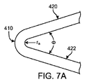
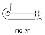
式3は、折り畳まれたストラット対、例えば図7Aのストラット420、422における幅がクラウン410の近傍で測定されようがストラット中間幅であろうが同じであると仮定する。クラウンがより多く形成され、それにより、そこで幅がリングストラット中間幅よりも大きくなると、Swiがクラウンでの幅によって測定される。また、ストラット間の最小空間は、隣接するクラウン(または谷部)の内径の2倍、すなわち、Crjによって規定される。
図6Bのスキャフォールド寸法において、クラウン幅はストラット中間幅よりも大きい。したがって、式3を用いると、Dminは、[16×(0.013)+12×(0.0005)+4×(0.0115)]×(1/π)+2×(0.011)=0.1048”(インチ)すなわち2.662mm(クラウンを通る断面で計算される最小直径)となる。代わりに断面がストラット中間幅(0.013ではなく0.0116)でとられた場合には、式3が0.0976”すなわち2.479mmを与える。
In the scaffold dimensions of FIG. 6B , the crown width is greater than the strut intermediate width. Therefore, using
なお、式3は、ストラットがほぼ正方形の断面を有することを前提とする。これは、図6Bのスキャフォールドにおける場合である(クラウンでのストラット断面寸法が0.011×0.013)。台形断面を伴うストラットを有するスキャフォールド、例えば、外径に対する壁厚の比率が図1の場合よりもかなり高くなるように小さい直径から切断されるスキャフォールドにおいて、Dminにおける更に正確な近似値は(ΣSwi+ΣCrj+ΣLwk)×(1/π)となる。これは、ストラットの厚さを越えて延びる表面が互いに当接する前に外面におけるストラットの縁同士がDminで当接するからである。
Note that
ガラス転移温度(以下、「Tg」と称する)は、高分子のアモルファス領域が大気圧で脆弱なガラス質状態から固体変形可能状態または延性状態に変化する温度である。すなわち、Tgは、高分子の鎖で部分運動が始まる温度である。所定の高分子のTgは、加熱速度に依存し得るものであり、高分子の熱履歴によって影響され得る。また、高分子の化学的構造は、高分子鎖の移動性に影響を与えることにより、ガラス転移に大きく影響を及ぼす。 The glass transition temperature (hereinafter referred to as “Tg”) is a temperature at which an amorphous region of a polymer changes from a brittle glassy state to a solid deformable state or a ductile state at atmospheric pressure. That is, Tg is the temperature at which partial motion begins in the polymer chain. The Tg of a given polymer can depend on the heating rate and can be affected by the thermal history of the polymer. In addition, the chemical structure of the polymer greatly affects the glass transition by affecting the mobility of the polymer chain.
「応力」とは、対象材料中の面内の小領域を通じて作用する力の場合のように単位面積当たりの力のことである。応力は、それぞれ垂直応力および剪断応力と呼ばれる、面に対して垂直および平行な成分に分けることができる。引張応力は、例えば、対象材料の拡張をもたらす(長さを増大させる)応力の垂直成分である。また、圧縮応力は、対象材料の圧縮をもたらす(長さを減少させる)応力の垂直成分である。 “Stress” refers to a force per unit area as in the case of a force acting through a small area in the surface of the target material. The stress can be divided into components normal and parallel to the plane, called normal stress and shear stress, respectively. Tensile stress is, for example, a normal component of stress that causes expansion of the material of interest (increasing length). The compressive stress is a vertical component of stress that causes compression (reducing the length) of the target material.
「歪み」は、所定の応力または負荷で材料に生じる拡張または圧縮の大きさのことである。歪みは、当初の長さの割合またはパーセンテージとして、すなわち、長さの変化を当初の長さで割った値として表わされてもよい。したがって、歪みは、拡張の場合にはプラスであり、圧縮の場合にはマイナスである。 “Strain” is the amount of expansion or compression that occurs in a material at a given stress or load. Distortion may be expressed as a percentage or percentage of the original length, i.e., the change in length divided by the original length. Thus, distortion is positive for expansion and negative for compression.
「弾性率」は、材料に印加される単位面積当たりの応力または力の成分を、印加力によってもたらされる印加力の軸に沿う歪みで割った比率として規定されてもよい。例えば、材料は、引張弾性率および圧縮弾性率の両方を有する。 “Elastic modulus” may be defined as the ratio of the stress or force component per unit area applied to a material divided by the strain along the axis of the applied force caused by the applied force. For example, the material has both a tensile modulus and a compressive modulus.
「靱性」または「破壊靱性」は、破壊前に吸収されるエネルギーの量、あるいは、同等に、材料を破壊するために必要とされる仕事量である。靱性の1つの指標は、ゼロ歪みから破断時の歪みまでの応力−歪み曲線下の面積である。応力は材料に作用する引張力に比例し、また、歪みはその長さに比例する。その結果、曲線下の面積は、高分子が破壊する前に伸長する距離にわたる力の積分に比例する。この積分はサンプルを破壊するために必要な仕事(エネルギー)である。靭性は、サンプルがその破壊前に吸収できるエネルギーの指標である。靭性と強度との間には違いがある。強いが頑丈ではない材料は脆弱であると言われる。脆性材料は強いが、破壊前にあまり変形することができない。 “Toughness” or “fracture toughness” is the amount of energy absorbed before fracture, or equivalently, the amount of work required to break a material. One measure of toughness is the area under the stress-strain curve from zero strain to strain at break. Stress is proportional to the tensile force acting on the material, and strain is proportional to its length. As a result, the area under the curve is proportional to the integral of the force over the distance the polymer stretches before breaking. This integration is the work (energy) required to destroy the sample. Toughness is a measure of the energy that a sample can absorb before it breaks. There is a difference between toughness and strength. Materials that are strong but not sturdy are said to be fragile. Brittle materials are strong, but cannot deform very much before breaking.
本明細書中で使用される用語「軸方向」および「長手方向」は、置き換え可能に使用され、ステントの中心軸または管状構造の中心軸と平行なあるいは略平行な方向、配向、または、ラインを指す。用語「周方向」とは、ステントまたは管状構造の外周に沿う方向のことである。用語「径方向」とは、ステントの中心軸または管状構造の中心軸に対して垂直または略垂直でかつ周方向の特性、すなわち、径方向強度を表わすために時として使用される方向、配向、または、ラインのことである。 As used herein, the terms “axial” and “longitudinal” are used interchangeably and refer to directions, orientations, or lines that are parallel or substantially parallel to the central axis of the stent or the central axis of the tubular structure. Point to. The term “circumferential” refers to the direction along the outer periphery of the stent or tubular structure. The term “radial” refers to a characteristic that is perpendicular or substantially perpendicular to the central axis of the stent or the central axis of the tubular structure and circumferential characteristics, ie, the direction, orientation, sometimes used to represent radial strength, Or it is a line.
用語「圧縮復元(crush recovery)」は、スキャフォールドが締め付け負荷または圧縮負荷からどのように復元するかを表わすために使用され、一方、用語「圧縮抵抗(crush resistance)」は、スキャフォールドの永久変形を引き起こすために必要とされる力を表わすために使用される。良好な圧縮復元性を有さないスキャフォールドまたはステントは、圧縮力の除去後にその当初の直径まで実質的に戻らない。前述したように、所望の径方向力を有するスキャフォールドまたはステントは、許容できない圧縮復元を有し得る。また、所望の圧縮復元を有するスキャフォールドまたはステントは、許容できない径方向力を有し得る。 The term “crush recovery” is used to describe how the scaffold recovers from a clamped or compressed load, while the term “crush resistance” is used to describe the permanent state of the scaffold. Used to represent the force required to cause deformation. A scaffold or stent that does not have good compressibility does not substantially return to its original diameter after removal of the compressive force. As previously mentioned, a scaffold or stent having the desired radial force may have unacceptable compression decompression. Also, scaffolds or stents having the desired compression recovery can have unacceptable radial forces.
図2に示される高分子スキャフォールドはポリ(L−ラクチド)(「PLLA」)チューブから形成される。このPLLAチューブを形成するためのプロセスは、米国特許出願第12/558,105号明細書(整理番号62571.382)に記載されるプロセスであってもよい。以下に記載されるように所望のスキャフォールド直径、厚さ、および、材料特性を有する図1のチューブを形成するために「変形される」前駆体について言及する。スキャフォールドのための開始チューブにおいて所望の特性をもたらすためにチューブが変形される前、あるいは、幾つかの例では拡張される前に、前駆体が形成される。前駆体は、その後にダイを通じて押し出される高分子の溶融温度を超えて加熱される未加工PLLA樹脂材料で始まる押出プロセスによって形成されてもよい。その後、一例では、拡張されたPLLAチューブを形成するための拡張プロセスは、PLLAガラス転移温度(すなわち、60〜70℃)を超えるが溶融温度(165〜175℃)を下回る温度、例えば約110〜120℃までPLLA前駆体を加熱することを含む。 The polymeric scaffold shown in FIG. 2 is formed from a poly (L-lactide) (“PLLA”) tube. The process for forming the PLLA tube may be the process described in US patent application Ser. No. 12 / 558,105 (Docket No. 65711.382). Reference is made to precursors that are “deformed” to form the tube of FIG. 1 with the desired scaffold diameter, thickness, and material properties as described below. The precursor is formed before the tube is deformed to provide the desired properties in the starting tube for the scaffold, or in some instances before it is expanded. The precursor may be formed by an extrusion process starting with a raw PLLA resin material that is heated above the melting temperature of the polymer that is subsequently extruded through a die. Thereafter, in one example, the expansion process to form an expanded PLLA tube is performed at a temperature above the PLLA glass transition temperature (ie, 60-70 ° C.) but below the melting temperature (165-175 ° C.), for example about 110-110. Heating the PLLA precursor to 120 ° C.
前駆体チューブはブロー成形プロセスによって径方向および軸方向に変形される。この場合、変形はチューブの長手方向軸に沿って所定の長手方向速度で徐々に生じる。後述するように、変形は、チューブが図2のスキャフォールドに形成される前にチューブの機械的特性を改善する。チューブ変形プロセスは、高分子鎖を径方向および/または二軸方向に配向するようになっている。再アライメントを引き起こす配向または変形は、変形プロセス中に材料結晶化度および結晶形成のタイプに影響を与えるべく、処理パラメータ、例えば圧力、熱(すなわち、温度)、変形速度の正確な選択にしたがって行なわれる。 The precursor tube is deformed radially and axially by a blow molding process. In this case, the deformation occurs gradually at a predetermined longitudinal velocity along the longitudinal axis of the tube. As described below, the deformation improves the mechanical properties of the tube before it is formed into the scaffold of FIG. The tube deformation process is intended to orient the polymer chains in the radial direction and / or biaxial direction. Orientations or deformations that cause realignment are performed according to an accurate selection of processing parameters such as pressure, heat (ie temperature), deformation rate to influence the material crystallinity and the type of crystal formation during the deformation process. It is.
別の例において、チューブは、ポリ(L−ラクチド−コ−グリコリド)、ポリ(D−ラクチド−コ−グリコリド)(「PLGA」)、ポリカプロラクトン(「PCL」)、これらの単量体のいずれかを組み合わせる任意の半結晶共重合体、または、これらの高分子の任意の混合物から形成されてもよい。スキャフォールドのための材料選択は、多くの末梢血管場所、特に手足付近に配置される末梢血管場所と関連付けられる複雑な負荷環境を考慮に入れるべきである。 In another example, the tube is made of poly (L-lactide-co-glycolide), poly (D-lactide-co-glycolide) (“PLGA”), polycaprolactone (“PCL”), any of these monomers It may be formed from any semi-crystalline copolymer, or any mixture of these polymers. The material selection for the scaffold should take into account the complex loading environment associated with many peripheral vascular locations, particularly those located near the limb.
大腿動脈は、様々な力が器具を同時に圧縮し、ねじり、伸長させ、あるいは、短くするため、脈管インプラントに対して動的な環境を与える。力の印加は、点荷重と分布荷重との間で、または、その組み合わせで、あるいは、時間に応じても変化する場合がある。最近の結果は、高結晶質PLLAから形成される生体吸収性のスキャフォールドが、血管に作用する永久的で一定の外向きの径方向力をもたらすことなく圧縮復元を行なうことができることを示した。永久的で一定の外向きの径方向力は、ニチノールの自己拡張型ステントに伴う後期臨床問題の原因となる場合がある。しかしながら、生体吸収性のスキャフォールドに伴う残りの課題は、それらのスキャフォールドを時間に応じて最適に破壊耐性にすること、すなわち、様々な動的負荷環境下でスキャフォールドの疲労寿命または生存性を改善することである。スキャフォールド、特に末梢血管に埋め込まれるスキャフォールドにおいては、破壊靱性を向上させる必要性が引き続いてある。 The femoral artery provides a dynamic environment for the vascular implant because various forces simultaneously compress, twist, stretch, or shorten the instrument. The application of force may vary between point loads and distributed loads, in combination, or as a function of time. Recent results have shown that a bioabsorbable scaffold formed from highly crystalline PLLA can perform compression decompression without producing a permanent, constant outward radial force acting on the blood vessels . Permanent, constant outward radial force may cause late clinical problems associated with Nitinol self-expanding stents. However, the remaining challenges associated with bioabsorbable scaffolds are to make them optimally fracture resistant over time, i.e., the fatigue life or viability of the scaffolds under various dynamic loading conditions. Is to improve. There is a continuing need to improve fracture toughness in scaffolds, particularly those embedded in peripheral blood vessels.
脈管スキャフォールドの破壊抵抗は、形状および材料に依存するだけでなく、製造プロセスおよび展開パラメータにも依存する。したがって、特に、スキャフォールドを均一に拡張させて展開させることができるようにするプロセス、設計、および、送達システムを有する必要がある。不均一な展開の結果として、場合により、スキャフォールドの様々なストラットおよびクラウンが非常に異なる力および動きに晒され、それにより、疲労寿命に悪影響が及ぶ。 The fracture resistance of a vascular scaffold not only depends on shape and material, but also on the manufacturing process and deployment parameters. Accordingly, there is a particular need to have a process, design, and delivery system that allows the scaffold to be uniformly expanded and deployed. As a result of non-uniform deployment, the various struts and crowns of the scaffold are sometimes exposed to very different forces and movements, thereby adversely affecting fatigue life.
材料の破壊靭性を特徴付けるのに役立つ有用な無次元数はデボラ数(固有材料減衰時定数と外部印加力の時定数との比)と呼ばれる。デボラ数が高いほど、過渡的な負荷または所定の振幅の疲労負荷の下で破壊するインプラントの予期される可能性が高くなる。 A useful dimensionless number that helps characterize the fracture toughness of a material is called the Deborah number (ratio of intrinsic material damping time constant to externally applied force time constant). The higher the Deborah number, the more likely it is to expect an implant to break under transient loads or fatigue loads of a given amplitude.
幾つかの方法で、すなわち、a)低いTgブロック、例えばブロック共重合体を含むためのバックボーン変更、b)ポリマーブレンド、c)光架橋をバックボーンへ導入することによって、強靱化領域をインプラント設計に導入することができる。 In some ways: a) Backbone modifications to include low Tg blocks, eg block copolymers, b) polymer blends, c) introduction of photocrosslinking into the backbone, toughening regions into the implant design Can be introduced.
PLLAなどのホモポリマーの破壊靱性は、最終的なインプラントの微細構造を制御することによって改善することもできる。%結晶化度、サイズ、および/または、結晶の分布、空間分布、および、結晶領域の勾配や形状などの変数。巨視的形状との組み合わせにおける微細構造制御の組み合わせ、例えば、スキャフォールドパターン、クリンププロセス等は、他のスキャフォールド材料特性、例えば径方向剛性および/または締め付け剛性に大きな悪影響を及ぼすことなく、破壊靭性を向上させる場合がある。 The fracture toughness of homopolymers such as PLLA can also be improved by controlling the microstructure of the final implant. Variables such as% crystallinity, size, and / or crystal distribution, spatial distribution, and gradient or shape of the crystalline region. A combination of microstructure control in combination with a macroscopic shape, for example, a scaffold pattern, a crimping process, etc., does not significantly affect other scaffold material properties, such as radial stiffness and / or clamping stiffness, and fracture toughness May be improved.
エラストマー特性を与えることに代わる手段は、「軟質」層および「硬質」層を有する多層構造の使用である。この場合、1つ以上の軟質層が高Tg材料から形成され、硬質層が高Tg材料を有する。同様の方法で、高低Tg領域は、ブロック共重合体または高分子混合物の使用によって典型的なゴム強靱化形態をもたらすことができる。所定の領域/ブロックのTgを所定のモノマーカらあるいはランダム共重合体のいくつかのモノマーの使用によってもたらすことができる。典型的な低Tg材料は、本開示にしたがって、カプロラクトン、ラクトン誘導体、炭酸塩、ブチルコハク酸エステル、炭酸トリメチレン、ジオキサノン、または、他の既知のモノマーカら形成することができる。使用され得る他の低Tg材料は、分解ではなく溶解によって腎臓をきれいにする材料である。そのような材料としては、本開示にしたがって、ポリエチレングリコール(PEG)、ポリビニルピロリドン(PVP)、または、ポリビニルアルコール(PVA)、または、他の既知の高分子を挙げることができる。 An alternative means of imparting elastomeric properties is the use of a multilayer structure with “soft” and “hard” layers. In this case, one or more soft layers are formed from a high Tg material and the hard layer has a high Tg material. In a similar manner, high and low Tg regions can provide typical rubber toughened forms through the use of block copolymers or polymer blends. The Tg of a given region / block can be brought about by the use of a given monomer or some monomer of a random copolymer. Typical low Tg materials can be formed from caprolactone, lactone derivatives, carbonates, butyl succinates, trimethylene carbonate, dioxanone, or other known monomers according to the present disclosure. Other low Tg materials that can be used are materials that clean the kidneys by dissolution rather than degradation. Such materials can include polyethylene glycol (PEG), polyvinyl pyrrolidone (PVP), or polyvinyl alcohol (PVA), or other known polymers in accordance with the present disclosure.
疲労特性を向上させる代わりの方法は、軸方向柔軟性の導入、および、特にコネクタリンクにおける予め定められた破壊点の使用である。破壊点は、実際の破壊、例えばひび割れや亀裂またはインプラントにおいて分布される小寸法の破壊の前駆体として機能し得る。亀裂またはひび割れの分布またはパターンは、特定の負荷、例えばねじれ、径方向力、引張りなどに晒されるときにスキャフォールドの予期される靱性のうちの1つを決定付けるあるいは知らせる場合がある。言うまでもないが、亀裂形成と結合した負荷環境との間の一般的に非常に非線形な関係に起因して、すなわち、同時に印加されて時間的に変化する曲げ、ねじれ、および、軸方向負荷に起因して、そのような予測方法を全ての状況に適用できない場合がある。 An alternative way to improve fatigue properties is the introduction of axial flexibility and the use of predetermined break points, especially in connector links. The failure point can serve as a precursor for actual failure, for example cracks and cracks or small dimension failures distributed in the implant. The distribution or pattern of cracks or cracks may determine or inform one of the expected toughness of the scaffold when exposed to a particular load, such as torsion, radial force, tension, and the like. Needless to say, due to the generally very non-linear relationship between crack formation and the coupled load environment, i.e. due to bending, twisting and axial loading applied simultaneously and time-varying. Such a prediction method may not be applicable to all situations.
疲れ特性を向上させる代わりの方法は、以下で更に詳しく説明するように、軸方向柔軟性の導入、および、予め定められた破壊点、特にコネクタリンクまたはその近傍における破壊点の使用である。 An alternative method of improving fatigue properties is the introduction of axial flexibility and the use of predetermined break points, particularly at or near the connector link, as described in more detail below.
約7mmの直径および約200ミクロンの壁厚、より具体的には8mmの直径および280ミクロンの壁厚を有する図1のチューブにおいては、拡張温度が華氏235±5°であり、拡張圧が110±10psiであり、拡張速度が0.68±0.20mm/秒である。 In the tube of FIG. 1 having a diameter of about 7 mm and a wall thickness of about 200 microns, more specifically an 8 mm diameter and a wall thickness of 280 microns, the expansion temperature is 235 ± 5 ° F. and the expansion pressure is 110 ± 10 psi and expansion speed is 0.68 ± 0.20 mm / sec.
高分子チューブが受ける径方向拡張の度合いは、引き起こされる周方向の分子配向および結晶配向の度合い、および、周方向の強度を部分的に特徴付けることができる。径方向拡張の度合いは、RE比=(拡張されたチューブの内径)/(チューブの当初の内径)として規定される径方向拡張(「RE」)比によって定量化される。また、RE比は、RE%=(RE比−1)×100%として規定されるパーセンテージとして表わすこともできる。高分子チューブが受ける軸方向伸長の度合いは、引き起こされる軸方向の分子配向および結晶配向、および、軸方向の強度を部分的に特徴付けることができる。軸方向伸長の度合いは、AE比=(拡張されたチューブの長さ)/(チューブの当初の長さ)として規定される軸方向伸長(「AE」)比によって定量化される。また、AE比は、AE%=(AE比−1)×100%として規定されるパーセンテージとして表わすこともできる。好ましい実施形態では、REが約400%であり、AEが40〜50%である。 The degree of radial expansion experienced by the polymer tube can partially characterize the degree of circumferential molecular and crystal orientation that is caused and the strength in the circumferential direction. The degree of radial expansion is quantified by the radial expansion (“RE”) ratio, defined as RE ratio = (inner diameter of expanded tube) / (original inner diameter of tube). The RE ratio can also be expressed as a percentage defined as RE% = (RE ratio−1) × 100%. The degree of axial elongation experienced by the polymer tube can partially characterize the axial molecular and crystal orientations that are caused and the axial strength. The degree of axial extension is quantified by the ratio of axial extension (“AE”) defined as AE ratio = (expanded tube length) / (original length of tube). The AE ratio can also be expressed as a percentage defined as AE% = (AE ratio−1) × 100%. In a preferred embodiment, the RE is about 400% and the AE is 40-50%.
図1の補強されて強化された円筒状の高分子チューブは、スキャフォールド構造に形成され、一実施形態では、図2に示されるようなパターン200(パターン200は平面図または扁平な図で示される)を形成する複数のストラット230およびリンク234を有する構造に形成され、パターンは、クリンプ前、および、バルーン拡張によって血管内でスキャフォールドがそのクリンプ状態からその展開状態に塑性変形または不可逆変形された後のスキャフォールドにおけるパターンに関する。つまり、図2のパターン200は(図3に三次元空間で部分的に示されるように)管状スキャフォールド構造を表わしており、そのため、軸A−Aがスキャフォールドの中心軸または長手方向軸と平行である。図3は、クリンプ前または展開後の状態のスキャフォールドを示している。図3から分かるように、スキャフォールドは、略管状体を形成するストラットおよびリンクの開放骨格を備える。図1の円筒状の変形チューブは、レーザ切断装置により、好ましくは切断中に冷却剤としてヘリウムガスを使用するピコ秒緑色レーザにより、図2〜図3に描かれるストラットおよびリンクから成るこの開放骨格へ形成されてもよい。
The reinforced and reinforced cylindrical polymer tube of FIG. 1 is formed into a scaffold structure, and in one embodiment, a
適したレーザプロセスの詳細は、米国出願第12/797、950号明細書(整理番号62571.404)において見出すことができる。ヘリウムガスは、レーザの切断経路に隣接するスキャフォールド構造を溶かすあるいは該スキャフォールド構造の特性を変えるのを回避するために必要である。典型的なレーザ加工パラメータが表1に与えられる。 Details of suitable laser processes can be found in US application Ser. No. 12 / 797,950 (Docket No. 62571.404). Helium gas is necessary to avoid melting the scaffold structure adjacent to the laser cutting path or changing the properties of the scaffold structure. Typical laser processing parameters are given in Table 1.
表1:約0.008” (=0.203mm)〜0.014” (=0.356mm)の壁厚を有する圧縮復元可能な高分子スキャフォールドに関するレーザ加工パラメータ

図2を参照すると、パターン200は、ストラット230によって形成される長手方向に離間されるリング212を含む。リング212は幾つかのリンク234によって隣接するリングに接続され、それぞれのリンクは軸A−Aと平行に延びる。スキャフォールドパターン(パターン200)のこの第1の実施形態では、4つのリンク234が、図2ではその左右にリングを有するリングを示す内部リング212を、2つの隣接するリングのそれぞれに対して接続する。したがって、リング212bは、4つのリンク234によってリング212cに接続されるとともに、4つのリンク234によってリング212aに接続される。リング212dは、図2の左にあるリングのみに接続される端部リングである。
Referring to FIG. 2, the
リング212は、クラウン207、209、210で接続されるストラット230によって形成される。リンク234は、クラウン209(W−クラウン)およびクラウン210(Y−クラウン)でストラット230と接合される。クラウン207(自由−クラウン)にはリンク234が接続されない。ストラット230は、クラウン中心から一定の角度を成してクラウン207、209、210から延びることが好ましい。すなわち、リング212は、正弦波曲線のパターン200とは対照的に、形状がほぼジグザグである。しかしながら、他の実施形態では、湾曲状のストラットを有するリングが考えられる。このように、この実施形態では、隣接するクラウン207、209/210間の長手方向距離であるリング212の高さは、クラウンで接続する2つのストラット230の長さと、クラウン角度θとから得ることができる。幾つかの実施形態では、リンク234が自由または非接続クラウン、W−クラウン、または、Y−クラウンに接続されるかどうかに応じて、異なるクラウンでの角度θが異なる。
リング212のジグザグ変化は、主に、スキャフォールドの外周にわたって(すなわち、図2のB−B方向に沿って)生じる。ストラット212の中心軸は、主に、スキャフォールドの長手方向軸からほぼ同じ径方向距離に位置する。理想的には、リングを形成するストラット間でのほぼ全ての相対的な動きは、クリンプ中および展開中において、径方向ではなく軸方向で生じる。以下で更に詳しく説明するが、高分子スキャフォールドは、多くの場合、位置ずれおよび/または不均一な径方向負荷が加えられることに起因して、この様式で変形しない。
The zigzag change of the
リング212は、クリンプ中に小さい直径まで潰すことができ、また、血管内での展開中に大きい直径まで拡張させることができる。開示の一態様によれば、クリンプ前直径(例えば、軸方向および径方向に拡張されたチューブの直径であり、該チューブからスキャフォールドが切断される)は、常に、送達バルーンが膨張時にもたらすことができる最大拡張スキャフォールド直径よりも大きい。一実施形態によれば、クリンプ前直径は、送達バルーンが過度に膨張され、あるいはバルーン−カテーテルのためのその最大使用直径を超えて膨張されるときであっても、スキャフォールド拡張直径よりも大きい。
パターン200は、リンク237によって形成される一対の横方向に離間される穴のそれぞれで放射線不透過性材料を受けるように形成される構造を有する4つのリンク237(それぞれの端部に2つ、図2には一方の端部だけが示される)を含む。これらのリンクは、クリンプ中にストラットをリンク上に折り重ねるのを妨げないように構成される。これは、以下で更に詳しく説明するように、最大でほぼDminの直径までスキャフォールドをクリンプできるようにするために、あるいは、スキャフォールドがクリンプ時に放射線不透過性マーカ保持構造のために利用できる空間を実質的に有さないようにするために必要である。
The
スキャフォールド構造の第2の実施形態は、図4に示されるパターン300を有する。パターン200と同様に、パターン300は、ストラット330によって形成される長手方向に離間されるリング312を含む。リング312は幾つかのリンク334によって隣接するリングに接続され、各リンクは軸A−Aと平行に延びる。図2に関連するリング212、ストラット230、リンク234、および、クラウン207、209、210と関連付けられる構造の先の説明は、第2の実施形態では4つではなく3つのストラット334だけがそれぞれ隣り合うリングの対を接続することを除き、第2の実施形態の対応するリング312、ストラット330、リンク334、および、クラウン307、309、310にも適用される。したがって、第2の実施形態において、リング312bは、3つのリンク234だけによってリング312cに接続されるとともに、3つのリンク334だけによってリング312aに接続される。リンク237と同様の放射線不透過性マーカを受けるように形成されるリンクは、リング312cとリング312dとの間に含まれてもよい。
A second embodiment of the scaffold structure has the
図5Aおよび図5Bは、各パターン300、200と関連付けられるクローズドセル要素の繰り返しパターンの態様をそれぞれ描いている。図5Aは、仮想ボックスVAによって境界付けられるパターン300の一部を示し、また、図5Bは、仮想ボックスVBによって境界付けられるパターン200の一部を示す。これらの図にはセル304およびセル204がそれぞれ示される。図5A、5Bでは、垂直基準軸が軸B−Bおよび長手方向軸A−Aによって示される。パターン200では、リング212のそれぞれの対によって4つのセル204が形成される。例えば、4つのセル204は、リング212b、212cと、このリング対同士を接続するリンク234とによって形成され、他の4つのセル204は、リング212a、212bと、このリング対同士を接続するリンクとによって形成され、その他も同様である。一方、パターン300では、3つのセル304がリング対とそれらの接続リンクとによって形成される。
5A and 5B depict aspects of a repeated pattern of closed cell elements associated with each
図5Aを参照すると、セル304の空間336、336aは、図示の長手方向に離間されるリング312b、312c部分と、リング312b、312cを接続する周方向に離間される平行なリンク334a、334cとによって境界付けられる。リンク334b、334dは、セル304を図3の左右に隣接するリングにそれぞれ接続する。リンク334bはW−クラウン309でセル304に接続する。リンク334dはY−クラウン310でセル304に接続する。「W−クラウン」とは、ストラット330とリンク334との間で延びるクラウン310の角度が鈍角(90°よりも大きい)であるクラウンのことである。「Y−クラウン」とは、ストラット330とリンク334との間で延びるクラウン309の角度が鋭角(90°よりも小さい)であるクラウンのことである。Y−クラウンおよびW−クラウンに関する同じ定義がセル204にも適用される。セル304においては8個の接続または自由クラウン307が存在し、これらのクラウンは、クラウンで接続されるリンク334を欠く8個のクラウンとして理解されてもよい。セル304においては、Y−クラウンとW−クラウンとの間に1つあるいは3つの自由クラウンが存在する。
Referring to FIG. 5A, the
図5Aのセル304の更なる態様は、それぞれのクラウン307、309、310における角度を含む。一般的には互いに等しくないこれらの角度(例えば、パターン300を有するスキャフォールドの「V2」および「V23」実施形態に関しては図6を参照)は、図5Aでは、それぞれがクラウン307、309、310と関連付けられる角度366、367、368として特定される。パターン300を有するスキャフォールドにおいては、ストラット330がストラット幅361とストラット長さ364とを有し、クラウン307、309、310がクラウン幅362を有し、また、リンク334がリンク幅363を有する。それぞれのリング312はリング高さ365を有する。クラウンにおける半径は一般に互いに等しくない。クラウンの半径は、図5Aでは、半径369、370、371、372、373、374として特定される。
Further aspects of the
セル304はW−Vクローズドセル要素として考えられてもよい。図6Aでは、「V」部分が文字「V」に似ている斜線領域336aを示す。残りの斜線が付されていない部分336、すなわち、「W」部分は、文字「W」に似ている。
図5Bを参照すると、セル204の空間236は、図示のように長手方向に離間されるリング212b、212cの部分と、これらのリングを接続する周方向に離間される平行なリンク234a、234cとによって境界付けられる。リンク234b、234dは、セル204を図2の左右に隣接するリングにそれぞれ接続する。リンク234bはW−クラウン209でセル236に接続する。リンク234dはY−クラウン210でセル236に接続する。セル204においては4つのクラウン207が存在し、これらのクラウンは、クラウンで接続されるリンク234を欠く4つクラウンとして理解されてもよい。セル204においては、それぞれのY−クラウンとW−クラウンとの間に1つの自由クラウンだけが存在する。
Referring to FIG. 5B, the space 236 of the
図5Bのセル204の更なる態様は、それぞれのクラウン207、209、210における角度を含む。一般的には互いに等しくないこれらの角度(例えば、パターン200を有するスキャフォールドの「V59」実施形態に関しては図6Bを参照)は、図5Bでは、それぞれがクラウン207、209、210と関連付けられる角度267、269、268として特定される。パターン200を有するスキャフォールドにおいては、ストラット230がストラット幅261とストラット長さ266とを有し、クラウン207、209、210がクラウン幅270を有し、また、リンク234がリンク幅264を有する。それぞれのリング212はリング高さ265を有する。クラウンにおける半径は一般に互いに等しくない。クラウンの半径は、図5Bでは、内側半径262および外側半径263として特定される。
Further aspects of the
セル204はW−クローズドセル要素として考えられてもよい。セル204によって境界付けられる空間236は文字「W」に似ている。
図5Aと図5Bとを比較すると、Wセル204が軸B−B、A−Aに関して対称であり、一方、W−Vセル304がこれらの軸の両方に関して非対称であるのが分かる。Wセル204は、リンク234間に1つのクラウン207しか有さないことを特徴とする。したがって、Y−クラウンまたはW−クラウンは、常に、パターン200のそれぞれのクローズドセルごとに、各クラウン207間にある。この意味では、パターン200は、それぞれがリンク234によって支持されないクラウンを1つしか有さないクローズドセルパターンを繰り返していると理解されてもよい。一方、W−Vセル304は、W−クラウンとY−クラウンとの間に3つの支持されないクラウン307を有する。図5Aから分かるように、リンク334dの左側に3つの支持されていないクラウン307が存在し、また、リンク334bの右側に3つの支持されていないクラウン307が存在する。
Comparing FIG. 5A and FIG. 5B, it can be seen that
パターン200を有するスキャフォールドの機械的挙動とパターン300を有するスキャフォールドの機械的挙動とは以下の点が異なる。これらの違いは、後述する他の違いと共に、生体内試験を含む図6A〜図6Bのスキャフォールド間の比較において観察された。ある点において、これらの試験は、例えば従来の見識が従来の金属ステントまたは冠状動脈スキャフォールドによりもたらされるときに、予期されずかつ従来の見識に反した本発明に係るスキャフォールドの機械的態様を実証した。したがって、特定の設計選択においては、臨床、製品歩留まり、および/または、送達プロファイルの要件によって決定されようとなかろうと、以下の特徴が留意されなければならない。
The mechanical behavior of the scaffold having the
一般に、圧縮復元可能な高分子スキャフォールドは、望ましい径方向の剛性、強度、および、破壊靱性を有し、目標送達直径まで、例えば少なくとも約Dminに至るまでクリンプされ得るとともに、強度/剛性対靱性、生体内性能対血管部位への送達のためのコンパクトさ、および、圧縮復元対径方向強度/剛性の3つの競合する設計属性を釣り合わせる。 In general, compressible decompressible polymer scaffolds have the desired radial stiffness, strength, and fracture toughness, and can be crimped to a target delivery diameter, for example, to at least about Dmin and strength / stiffness vs. toughness Balancing three competing design attributes: in vivo performance vs. compactness for delivery to the vascular site, and compression decompression vs. radial strength / rigidity.
生体内性能対血管部位への送達のためのコンパクトさとは、送達直径に至るまでスキャフォールドをクリンプできる能力のことである。W−セル204を形成するようにクラウンを接続するリングストラット230は、反管腔側の面に接する軸(軸A−A)を中心とする回転が更に抑制さえる。W−VセルのV部分の場合、クラウンは、接続リンク334の数の減少に起因して、特定の形状下で軸A−Aを中心にねじれ易い場合がある。実際には、リング部分が「反転する」可能性があり、それにより、回転し、あるいは、座屈の結果として面外に撓む(「面外」とは、スキャフォールドの弓形の円筒状の面の外側の撓みのことであることに留意されたい。図5Aを参照すると、「面外」は、この図の表面に対して垂直にストラットが撓むことを意味する)。図5Bの場合のようにクラウンまたは谷部のそれぞれにリンク234が存在する場合には、クラウンが座屈しあるいは反転する任意の傾向が減少される。これは、リングストラットがリンク236によって更に抑制されるからである。本質的に、リンクは、リングにわたる負荷をより均一に釣り合わせる役目を果たす。
In vivo performance versus compactness for delivery to a vascular site is the ability to crimp the scaffold down to the delivery diameter. The
米国特許出願第12/861,719号明細書(整理番号62571.448)に更に詳しく記載されて図示されるように、パターン300にしたって構成されるスキャフォールドにおける「反転(flipping)」現象はクリンプ中に観察された。W−Vセル304は、隣接するクラウンまたは谷部の過度のねじれを抑制するために、クラウン307で隣接リンク334を欠いている。本質的に、リンク334間に2つのクラウン307が存在する場合、リングのV部分の反転または座屈を防止する拘束は、個々のリングストラット330の座屈強度、すなわち、ねじれにおける高分子ストラットの強度および剛性に依存する。しかしながら、1つのリンク234がそれぞれの隣接するクラウン/谷部に接続される場合(図5B)には、接続されるリンク234によって加えられる曲げ剛性に起因して、クラウン207での面外撓みが更に抑制され、それにより、隣接するクラウン207でのねじれが抑制される。
As described and illustrated in more detail in US patent application Ser. No. 12 / 861,719 (Docket No. 6571.448), the “flipping” phenomenon in a scaffold constructed according to
それに対応して、パターン200にしたがったスキャフォールドは、同様に構成されるパターン300にしたがったスキャフォールドよりも剛性が高い。パターン200にしたがったスキャフォールドは、軸方向および長手方向の両方の曲げにおいて剛性が高い。これは、より多くのリンク236が使用されるからである。しかしながら、高い剛性が望ましくない場合がある。剛性が高くなると、剛性のより低いスキャフォールドにわたって大きな亀裂が形成される可能性がある。例えば、更なるリンクによって付加される剛性は、特にスキャフォールドが曲げ(リングが互いに対して移動する)と径方向圧縮および/または締め付け(圧縮)との組み合わせに晒される場合には、更なるリンク234により互いに接続されるリングに対して更に大きな応力をもたらす可能性がある。リンク234の存在は、リングの剛性を更に大きくすることに加えて、更なる負荷経路をリングにもたらす。
Correspondingly, the scaffold according to the
生体内条件は、パターン200にしたがったスキャフォールドに有利に働く可能性があるが、パターン300にしたがったスキャフォールドは、送達直径に至るまで更に容易にクリンプされ得る。また、他のファクタもスキャフォールドをクリンプできる能力に影響を及ぼす。本開示によれば、クリンプ前のスキャフォールドにおける約115°未満のクラウン角度は、(1つのケースでは6.5mmの膨張直径に対して)更に高いクラウン角度を有するスキャフォールドよりもあまり破壊の問題や関連する展開の問題(例えば、リングストラットの不均一な折り畳み/拡開)を引き起こし得ないことが分かった。スキャフォールドは、約7.4mmまで膨張され得るバルーンまでクリンプされる。したがって、バルーンが過度に膨張されると、スキャフォールドが最大で約7mmの膨張直径を達成する。本開示に係るバルーンカテーテル−スキャフォールドアセンブリにおいて、バルーンにおける最大膨張直径はクリンプ前のスキャフォールド直径以下である。前述したように、スキャフォールドにおける最大膨張直径はクリンプ前のスキャフォールド直径よりも小さいことが好ましい。
In vivo conditions may favor a scaffold according to
望ましいクリンプ形状を有する圧縮復元可能な高分子スキャフォールドを設計する過程中に、8mm直径でスキャフォールドを形成する際には、2つの理由により、スキャフォールドを所望のクリンプ形状にクリンプすること、例えば、スキャフォールドを8mm直径から約2mm形状にクリンプすることが難しいことが分かった。第1に、350〜400%直径減少要件を課すことにより、高分子材料は、この大きな直径減少に晒されるときにスキャフォールドによって受けられる歪みレベルに単に起因して、亀裂形成および亀裂伝搬を更に生じ易かった。この懸念は、剛性を調整することによって、例えばストラット角度、壁厚、および/または、クラウンの数を減少させることによって対処された。また、チューブ(図1)を形成するために使用されるプロセスステップは、前述したように、亀裂形成および亀裂伝搬に対するスキャフォールドの抵抗を高めるのに役立つことが分かった。 During the process of designing a compressible decompressible polymer scaffold having a desired crimp shape, when forming a scaffold with an 8 mm diameter, the scaffold may be crimped to the desired crimp shape for two reasons, for example It was found that it was difficult to crimp the scaffold from an 8 mm diameter to about 2 mm shape. First, by imposing 350-400% diameter reduction requirements, the polymeric material is further subject to crack formation and crack propagation simply due to the level of strain experienced by the scaffold when exposed to this large diameter reduction. It was easy to occur. This concern has been addressed by adjusting the stiffness, for example by reducing the strut angle, wall thickness, and / or the number of crowns. Also, the process steps used to form the tube (FIG. 1) have been found to help increase the scaffold's resistance to crack formation and crack propagation, as described above.
第2に、亀裂形成を制限するようにスキャフォールド寸法が調整された場合であっても、スキャフォールドのための空間をクリンプ形状の範囲内に制限するという問題が存在した。クリンプされるスキャフォールドと関連付けられる材料の質量に起因して、所望のクリンプ形状へのリングの圧縮に利用できる空間は、受け入れられない降伏応力または破壊をもたらさなければ得られなかった。したがって、亀裂問題または展開問題を伴うことなく350〜400%直径減少が達成できた場合であっても、スキャフォールドパターンは、スキャフォールド構造が可能とする関節の範囲を超えなければ更なる減少を可能にしない。 Second, there was a problem of limiting the space for the scaffold within the crimp shape even when the scaffold dimensions were adjusted to limit crack formation. Due to the mass of material associated with the crimped scaffold, the space available for compression of the ring into the desired crimp shape could only be obtained if it resulted in unacceptable yield stress or failure. Thus, even if a 350-400% diameter reduction can be achieved without cracking or deployment problems, the scaffold pattern can be further reduced if it does not exceed the range of joints that the scaffold structure allows. Not possible.
本開示の他の態様によれば、スキャフォールドの破壊靱性を高めるおよび/または送達直径を減少させるようになっているスキャフォールドのための改良されたクラウン構造が存在する。形状減少限界を克服し、かつPLGAのPLLAのような脆性高分子を使用して実施され得る既存のスキャフォールドパターンへの設計変更が、クラウン/谷部を形成するストラットをブリッジするクラウンまたは谷部の内側半径のサイズをかなり減少させることが分かった。 According to another aspect of the present disclosure, there is an improved crown structure for a scaffold that is adapted to increase the fracture toughness of the scaffold and / or reduce the delivery diameter. A crown or trough that overcomes the shape reduction limit and that changes to an existing scaffold pattern that can be implemented using a brittle polymer such as PLLA's PLLA bridges the struts that form the crown / valley It was found to significantly reduce the size of the inner radius of.
図7Aおよび図7Bは、クラウン410近傍の一対のストラット420、422を示している。クリンプ前状態では、ストラット420、422がクラウン角度φだけ離間されるとともに、クラウンが内側半径raを伴って形成される。これはクラウンにとって典型的な構造である。内側半径は、クラウンでの応力集中を回避するように選択される。技術が教示したように、クラウンなどのヒンジ点で形状の劇的な変化が存在すると、クラウンにわたる曲げにおける慣性モーメントが不連続となるため、亀裂または降伏がヒンジ点で形成される可能性が更に高まる(それにより、径方向強度に影響が及ぶ)。
7A and 7B show a pair of
金属ステントの場合、クリンプ前の角度φは、ステントが展開されるときの角度よりも小さい。小径のステントを形成することにより、ステントを小さな形状まで更に容易にクリンプできる。内側半径の存在に起因して、径方向剛性を失うことなく、展開時に角度φを超えることができる。しかしながら、この半径が非常に小さくかつ展開時のストラット角度がφを超える場合には、内側半径での応力集中に起因して、降伏または他の問題が発現する機会が高まる。金属の延性および弾力性に起因して、金属から形成されるステントを図7Bに示されるよりも更に小さくクリンプすることもできる。ストラット420、422が互いに接触してもよい。すなわち、Sが2×raよりも小さいが、ステントは、過度なクリンプ状態にもかかわらず、依然として復元してその径方向の剛性を維持できる。
In the case of a metal stent, the angle φ before crimping is smaller than the angle when the stent is deployed. By forming a small diameter stent, the stent can be more easily crimped to a smaller shape. Due to the presence of the inner radius, the angle φ can be exceeded during deployment without losing radial stiffness. However, if this radius is very small and the strut angle during deployment exceeds φ, the chances of yielding or other problems appear due to stress concentration at the inner radius. Due to the ductility and elasticity of the metal, a stent formed from metal can be crimped even smaller than shown in FIG. 7B. The
しかしながら、高分子スキャフォールドにおいては、距離S(図7B)を一般に半径raにおいて許容されるよりも小さくすべきでないことが分かった。すなわち、Sは2ra以上である。高分子スキャフォールドの場合、ストラット420、422が互いに接近されれば、すなわち、Sが2×ra未満になれば、スキャフォールドが展開される際に材料の脆性が破壊問題をもたらす可能性があり得る。したがって、スキャフォールドは、半径において許容できる距離を超えてクリンプされれば、その径方向剛性を維持できない場合がある。図8A、図8F、図8Gとして含まれる走査型電子顕微鏡(SEM)写真は、図7Bの距離Sが2×ra未満のときのクラウンでの破壊を示している。これらの写真から分かるように、Wクラウン、自由クラウンおよびYクラウンではかなりの材料破壊がある。
However, in the polymer scaffold, the distance S was found not to be smaller than allowed in general radius r a (Figure 7B). That, S is not less than 2r a. For the polymer scaffold, if
ストラット420、422間の距離S(図7B)を減少させる目的で、本発明者等は、当技術分野により与えられるアドバイスにもかかわらず、半径raを可能な限り小さくすることを決めた。驚いたことに、径方向強度の大きな目立った再び生じる、あるいはひどく高い損失を伴うことなく、スキャフォールドがクリンプ状態から拡張状態まで復元できることが分かった。図8B、図8C、図8Dとして与えられるSEMは、クリンプ後に半径が減少してその後にバルーンにより拡張したクラウン/谷部を示している。これらの例において、クラウン内側半径は、切断工具(前述した緑色光ピコ秒レーザ)が形成できたと同程度に小さく形成された。図8A、図8F、図8Gと図8B、図8C、図8Dとを比較すれば分かるように、小さい半径を有するスキャフォールドは幾つかのボイドを生成したが、亀裂伝搬は存在しない。構造的な完全性が維持された。これらの写真の展開されたスキャフォールドは良好な径方向剛性を維持した。
In order to reduce the distance between the
図7Cおよび図7Dは、これらの予期しない結果をもたらしたクラウン形成の実施形態を示している。ここに描かれるクラウン形成の小さい半径を有するタイプのWセルの一例が図5Bおよび図6Bに示される。半径rbは約0.00025インチであり、これはレーザによって形成され得る最小半径に対応する。0.00025インチ半径は、目標半径としてあるいは半径サイズの限界として考えられないが、それはこの実施形態にとって望ましい結果をもたらした。むしろ、小さい形状サイズを得るために、半径は可能な限りゼロに近くてもよいと考えられる。したがって、当業者であれば分かるように、実施形態における半径は、本開示にしたがって本発明を実施するために、この半径よりも大きいあるいはこの半径よりも小さい約0.00025(切断工具に応じて)となり得る。例えば、クリンプサイズを望み通りに減少させるように半径が選択されてもよいと考えられる。 Figures 7C and 7D illustrate crown formation embodiments that have produced these unexpected results. An example of a W cell of the type depicted here having a small radius of crown formation is shown in FIGS. 5B and 6B. Radius r b is about 0.00025 inches, which corresponds to the minimum radius that can be formed by a laser. A 0.00025 inch radius is not considered as a target radius or radius size limit, but it has produced desirable results for this embodiment. Rather, it is contemplated that the radius may be as close to zero as possible to obtain a small feature size. Accordingly, those skilled in the art will appreciate that the radius in the embodiment is about 0.00025 (depending on the cutting tool) greater than or less than this radius to practice the invention in accordance with the present disclosure. ) For example, it is contemplated that the radius may be selected to reduce the crimp size as desired.
ほぼゼロの内側半径は、開示の目的のため、クラウン構造を形成する工具において可能な最小半径を意味する。幾つかの実施形態に係る内側半径は、距離Sがほぼゼロまで減少できるようにする半径を意味する。すなわち、図7Dに示されるように、ストラット同士が隣接しおよび/または互いに接触する(S’がほぼゼロまたはゼロである)。 A near zero inner radius means for purposes of disclosure the smallest radius possible in a tool that forms a crown structure. An inner radius according to some embodiments refers to a radius that allows the distance S to be reduced to approximately zero. That is, as shown in FIG. 7D, the struts are adjacent and / or in contact with each other (S ′ is approximately zero or zero).
本発明に係るスキャフォールドをどのようにして強度損失を伴わずに理論最小半径まで減少した後に拡張できるのかに関する、特定の理論に縛られるのを望むことなく、膨張直径よりも大きい開始直径の選択が有利な結果に役立つと考えられる。金属ステントがその膨張直径よりも小さい直径から形成されて、その小さい直径がより小さいクリンプ形状を促進するべく選択されてもよい先の例とは対照的に、好ましい実施形態に係る高分子スキャフォールドは、バルーンカテーテル−スキャフォールドアセンブリにおける最大膨張直径よりも大きい開始直径から形成される(大きい開始直径は、後述するように急激な反跳を減らすため、および/または、図1のチューブにおけるチューブ処理ステップで前述したように展開状態での径方向強度特性を高めるために好ましい場合がある)。このように、クリンプ前ストラット角度は、スキャフォールドが展開されるときの最大クラウン/ストラット角度よりも大きいことが好ましい。つまり、バルーンがスキャフォールドをクリンプ状態から展開状態に拡張させるときには、決して図7Cのクラウン角度(クリンプ前角度)を超えない。圧縮復元可能な高分子スキャフォールドの特徴、すなわち、展開クラウン角度よりも大きいクリンプ前クラウン角度は、従来技術の教示内容に反して、最小内側半径がウラウン形成のために使用されたときにSEM写真における高分子スキャフォールドがどのように径方向強度を保持するのかに関する手掛かりを与えると考えられる。血管により負荷が掛けられる際のスキャフォールドの拡張ではなく圧縮は、ボイドの存在にもかかわらず、更なる脆弱化をもたらさないと考えられる。クラウンがそのクリンプ前形状(図7C)に対して圧縮変形のみを受けると、内側半径近傍の潜在的に脆弱化された領域が圧縮応力のみに晒され、そのため、クラウンが引き裂かれることがなく、すなわち、亀裂伝搬を引き起こさない。 Selection of a starting diameter larger than the expanded diameter without wishing to be bound by a particular theory on how the scaffold according to the present invention can be expanded after being reduced to the theoretical minimum radius without loss of strength Are considered to be useful for advantageous results. In contrast to the previous example, where the metal stent is formed from a diameter smaller than its expanded diameter, and the small diameter may be selected to promote a smaller crimp shape, the polymeric scaffold according to the preferred embodiment Is formed from a starting diameter that is larger than the maximum inflated diameter in the balloon catheter-scaffold assembly (a large starting diameter is used to reduce abrupt recoil as described below and / or tube treatment in the tube of FIG. As described above in the step, it may be preferable to enhance the radial strength characteristics in the deployed state). Thus, the pre-crimp strut angle is preferably greater than the maximum crown / strut angle when the scaffold is deployed. That is, when the balloon expands the scaffold from the crimped state to the deployed state, it never exceeds the crown angle (pre-crimp angle) of FIG. 7C. The characteristics of the compressible polymer scaffold, ie, the pre-crimp crown angle that is larger than the unfolded crown angle, is contrary to the teaching of the prior art, when the minimum inner radius is used for uraun formation. It is thought that this gives a clue as to how the polymer scaffolds in the glass retain the radial strength. It is believed that compression rather than expansion of the scaffold when loaded by a blood vessel does not result in further weakening despite the presence of voids. When the crown only undergoes compressive deformation against its pre-crimp shape (FIG. 7C), the potentially weakened area near the inner radius is exposed only to compressive stress, so that the crown is not torn, That is, it does not cause crack propagation.
米国特許出願第12/861,719号明細書(整理番号62571.448)に詳しく記載されるスキャフォールドのクリンプは、高分子のガラス転移温度よりも低いがガラス転移温度付近の温度まで高分子材料を加熱することを含む。一実施形態において、クリンプ中のスキャフォールドの温度は、PLLAにおけるガラス転移温度よりも約5〜10°低い温度まで上昇される。最終クリンプ直径までクリンプされると、最終ドウェル期間にわたってクリンプジョーが最終クリンプ直径で保持される。圧縮復元を成す高分子スキャフォールドをクリンプするこの方法は、クリンプジョーが解放されるときの反跳を減らすために有益である。しかしながら、内側半径を小さくする本開示の態様に関して他の予期しない結果が見出された。ドウェル期間中に、高分子スキャフォールドのクリンプ形状を理論最小形状よりも小さい形状まで小さくできることが分かった。 The scaffold crimp described in detail in US patent application Ser. No. 12 / 861,719 (Docket No. 6571.448) is a polymeric material that is below the glass transition temperature of the polymer but to a temperature near the glass transition temperature. Heating. In one embodiment, the temperature of the scaffold during crimping is raised to a temperature that is about 5-10 degrees below the glass transition temperature in PLLA. Once crimped to the final crimp diameter, the crimp jaws are held at the final crimp diameter for the final dwell period. This method of crimping a polymer scaffold that provides compression decompression is beneficial to reduce recoil when the crimp jaws are released. However, other unexpected results have been found for aspects of the present disclosure that reduce the inner radius. During the dwell period, it was found that the crimp shape of the polymer scaffold could be reduced to a shape smaller than the theoretical minimum shape.
図6Bのスキャフォールドに関して先に与えられた例から、Dminにおける値は0.1048”すなわち2.662mmである。米国特許出願第12/861,719号明細書(整理番号62571.448)に記載されかつ先に要約されたクリンプ手順にしたがってこのスキャフォールドをクリンプすると、スキャフォールドを0.079”すなわち2.0066mmのクリンプ形状まで小さくできることが分かった。そのため、このスキャフォールドにおいて、クリンプ形状はDmin未満であった。この形状により、0.085” (=2.159mm)外径の保護シースをスキャフォールド上にわたって配置できる。薬剤コーティングがスキャフォールド上にわたって配置された際には、シースを伴うスキャフォールドの形状が0.092” (=2.334mm)であった。このスキャフォールドにおいては、径方向強度の範囲が0.45〜0.65N/mmであり、径方向剛性の範囲が1.00〜1.20N/mmであり、圧縮復元可能性が約90%(50%圧縮)であった。 From the example given above with respect to the scaffold of FIG. 6B, the value in Dmin is 0.1048 "or 2.662 mm. As described in US patent application Ser. No. 12 / 861,719 (Docket No. 62571.448). It has been found that crimping this scaffold according to the crimp procedure outlined above and previously summarized can reduce the scaffold to a crimp shape of 0.079 "or 2.0066 mm. Therefore, in this scaffold, the crimp shape was less than Dmin. This shape allows a protective sheath with an outer diameter of 0.085 " (= 2.159 mm) to be placed over the scaffold. When the drug coating is placed over the scaffold, the shape of the scaffold with the sheath is zero. 0.092 " (= 2.334 mm) . In this scaffold, the radial strength range is 0.45 to 0.65 N / mm, the radial stiffness range is 1.00 to 1.20 N / mm, and the compression recovery possibility is about 90%. (50% compression).
ドウェル期間中の材料の圧縮に起因してDmin未満の小さい形状が得られたと考えられる。本質的に、高い温度でドウェル期間中にクリンプジョーによって課される圧力により、リングを形成するストラットが一緒に圧縮されてクリンプスキャフォールド形状まで更に小さくなる。これらの実施形態によれば、その理論最小形状よりも小さい形状を成すクリンプされたスキャフォールドは、生体内でうまく展開されて検査された。このスキャフォールドは、50%の直径減少後の約90%を上回る望ましい圧縮復元に加えて、望ましい径方向剛性特性を有した。 It is considered that a small shape of less than Dmin was obtained due to compression of the material during the dwell period. In essence, the pressure imposed by the crimp jaws during the dwell period at high temperatures causes the struts forming the ring to be compressed together and further reduced to the crimp scaffold shape. According to these embodiments, crimped scaffolds that were smaller than their theoretical minimum shape were successfully deployed and examined in vivo. This scaffold had desirable radial stiffness characteristics in addition to desirable compression recovery greater than about 90% after a 50% diameter reduction.
この開示の他の態様において、圧縮復元可能な高分子スキャフォールドのためのストラットおよびクラウンの形成は、図7Aに示されるクラウン形成を成すスキャフォールドにおけるクリンプ形状よりも小さいクリンプ形状を達成する目的で、図7Eに描かれる形状を成すように形成される。これらの実施形態によれば、クラウンが図示のように半径rcに形成される。このスキャフォールドがクリンプされると、ストラットを互いに接近させることができ、それにより、これらのストラットを離間させる距離がほぼゼロ(S”がほぼゼロまたはゼロである)になる。図7Cの実施形態とは異なり、半径rcは、ストラットの端部とクラウンの端部との間に穴または拡大領域を形成することにより、何らかの有限のあるいはより大きな半径にされる。その内面に沿って内側半径を形成するクラウンにおける厚さt’cは、ストラット幅より小さくてもよい(図7Cおよび図16の例では、クラウン厚さがストラット幅より大きくてもよい)。これにより、クリンプ形状を大きくすることなく更に大きな内側半径をクラウンで使用できる。 In another aspect of this disclosure, strut and crown formation for a compressible decompressible polymer scaffold is intended to achieve a crimp shape that is smaller than the crimp shape in the crown-forming scaffold shown in FIG. 7A. , To form the shape depicted in FIG. 7E. According to these embodiments, the crown is formed radially r c as shown. When the scaffold is crimped, the struts can be brought closer together, thereby causing the distance to separate the struts to be approximately zero (S ″ is approximately zero or zero). The embodiment of FIG. Unlike, the radius r c, by forming a hole or enlarged region between the end portion and the crown end of the strut, is to some finite or larger radius. inner radius along its inner surface The thickness t ′ c in the crown that forms the shape may be smaller than the strut width (in the examples of FIGS. 7C and 16, the crown thickness may be larger than the strut width), thereby increasing the crimp shape. Even larger inner radii can be used with crowns.
これらの実施形態において、図7E〜図7Fに描かれるクラウン形成を成すスキャフォールドは、「鍵穴」クラウン形成と称される。この名は、内壁面により形成される鍵穴スロットまたは開口を示す図7Fを参照することにより更に説明しなくても理解できる。クリンプ形状では、クラウン近傍のストラットが互いに接近される一方で、半径rcを有する穴または開口がクラウンでほぼ維持される。距離S”は、「鍵穴」クラウン形成においては半径rcの2倍よりも小さい。 In these embodiments, the crown-forming scaffold depicted in FIGS. 7E-7F is referred to as a “keyhole” crown formation. This name can be understood without further explanation by referring to FIG. 7F which shows a keyhole slot or opening formed by the inner wall surface. The crimp shape, while the crown near the struts are closer to each other, the holes or openings having a radius r c is substantially maintained in the crown. The distance S "is smaller than twice the radius r c is in the" key "crown formation.
パターン300、200を具現化するスキャフォールドの例が図6A〜図6Bに与えられる(0.008インチ壁厚を有するV2実施形態、0.008インチおよび0.014インチの壁厚を有するV23実施形態、および、0.011インチ壁厚を有するV59実施形態と称される)。図5A〜図5Bの様々なセル属性のための特定の値が与えられる。
Examples of scaffolds that embody
8mmのクリンプ前直径を有するスキャフォールドV59(パターン200)は、非順応性バルーンまでクリンプされ得る。この場合、クリンプ形状は約2mmである。この例では、膨張直径が約6.5mmである。クリンプ前直径7、9をそれぞれ有するスキャフォールドV2、V23は、非順応性バルーンにより約6.5mmまで拡張される。V2、V23スキャフォールドは約0.092インチ(2.3mm)の直径までクリンプさせることができる。
Scaffold V59 (pattern 200) having a pre-crimp diameter of 8 mm can be crimped to a non-compliant balloon. In this case, the crimp shape is about 2 mm. In this example, the expanded diameter is about 6.5 mm. Scaffolds V2, V23 having
本開示によれば、スキャフォールドのストラットのアスペクト比(AR)が約0.8〜1.4であってもよく、リンクのARが約0.4〜0.9であってもよく、あるいは、リンクおよびストラットの両方のARが約0.9〜1.1または約1であってもよいことが分かった。アスペクト比(AR)は厚さに対する幅の比率として規定される。したがって、0.0116の幅および0.011の壁厚を有するストラットに対しては、ARは1.05である。 According to the present disclosure, the scaffold strut aspect ratio (AR) may be about 0.8 to 1.4, the link AR may be about 0.4 to 0.9, or It has been found that both the link and strut ARs may be about 0.9-1.1 or about 1. Aspect ratio (AR) is defined as the ratio of width to thickness. Thus, for a strut having a width of 0.0116 and a wall thickness of 0.011, the AR is 1.05.
本開示によれば、圧縮復元可能性を有するバルーン拡張型の高分子スキャフォールドは、約0.3N/mmよりも大きい径方向強度または約0.32〜0.68N/mmの径方向強度を有するとともに、約0.5N/mmよりも大きい径方向剛性または約0.54〜1.2N/mmの径方向剛性を有する。本開示によれば、圧縮復元可能なスキャフォールドは、約0.008” (=0.203mm)〜0.014” (=0.356mm)の壁厚を有するスキャフォールドにおいてこれらの範囲の剛性および強度を有するとともに、約2mmクリンプ形状から6.5mm非順応性バルーンによって展開されるように構成され、あるいは、バルーンカテーテル上の約2mmの交差形状から約6.5mm〜7mmの直径に展開されるように構成される。 According to the present disclosure, a balloon-expandable polymer scaffold with compressibility can have a radial strength greater than about 0.3 N / mm or a radial strength of about 0.32-0.68 N / mm. And having a radial stiffness greater than about 0.5 N / mm or a radial stiffness of about 0.54-1.2 N / mm. According to the present disclosure, a compressible decompression scaffold has a stiffness in these ranges in a scaffold having a wall thickness of about 0.008 " (= 0.203 mm) to 0.014" (= 0.356 mm) and It is strong and configured to be deployed by a 6.5 mm non-compliant balloon from a crimped shape of about 2 mm, or it is deployed from a crossed shape of about 2 mm on the balloon catheter to a diameter of about 6.5 mm to 7 mm. Configured as follows.
PLLAなどの生体分解性高分子(および、一般に炭素、水素、酸素、窒素から成る高分子)が、放射線不透過性を伴わず、放射線透過性である。スキャフォールドは放射線不透過性でありあるいはX線透視下で見えることが望ましく、それにより、スキャフォールド本体、好ましくは端部リングをリアルタイムに視覚化することで、血管内での正確な配置を容易に行なえる。心臓科医師またはインターベンショナル・ラジオロジストは、一般に、患者の脈管構造を通じて送達カテーテルを追跡し、蛍光透視または同様のX線視覚化法を使用して、病変部位にスキャフォールドを正確に配置する。スキャフォールドをX線透視下で見えるようにするためには、スキャフォールドが周辺組織よりも多くのX線を吸収しなければならない。スキャフォールドにおけるX線不透過性材料がその直接的な視覚化を可能にしてもよい。これらの材料を生体分解性高分子スキャフォールドと共に含ませる1つの方法は、例えば米国特許出願第11/325,973号明細書(整理番号62571.45)に記載される技術を使用してX線不透過性マーカをスキャフォールドの構造要素に取り付けることである。しかしながら、他のステントまたはスキャフォールドとは異なり、本開示に係る圧縮復元可能性を有する生体分解性、生体吸収性、生体再吸収性、または、生体内分解性の末梢血管に埋め込まれるスキャフォールドは、公知技術で適切に扱われない特別な要件を有する。 Biodegradable polymers such as PLLA (and generally polymers consisting of carbon, hydrogen, oxygen, nitrogen) are radiopaque without radiopacity. The scaffold should be radiopaque or visible under fluoroscopy, which facilitates accurate placement within the vessel by visualizing the scaffold body, preferably the end ring, in real time It can be done. A cardiologist or interventional radiologist typically tracks the delivery catheter through the patient's vasculature and uses fluoroscopy or similar X-ray visualization to accurately place the scaffold at the lesion site To do. In order for the scaffold to be visible under fluoroscopy, the scaffold must absorb more X-rays than the surrounding tissue. Radiopaque material in the scaffold may allow its direct visualization. One way of including these materials with a biodegradable polymer scaffold is by X-ray using techniques described, for example, in US patent application Ser. No. 11 / 325,973 (Docket No. 6571.45). Attaching an impermeable marker to the structural element of the scaffold. However, unlike other stents or scaffolds, a scaffold embedded in a biodegradable, bioabsorbable, bioresorbable, or biodegradable peripheral blood vessel that has compressibility according to the present disclosure is Have special requirements that are not properly handled by the known art.
最小クリンプ直径、例えばDminを増大させることなくマーカ保持材料(マーカ構造)の近傍で所望の剛性特性を維持するという満たされない必要性が存在する。マーカ保持材料は、特に300〜400%の直径減少を有するスキャフォールドの場合に、あるいは更には、開始クリンプ前直径から送達直径にクリンプされる際に、および/または、目標送達直径が最大でもほぼスキャフォールドの理論最小直径(Dmin)となる場合に、送達カテーテル上のクリンプされたスキャフォールドにおいて必要とされる交差形状または送達直径を得るために利用できる非常に限られた空間を妨げてはならない。クリンプ中に所望の送達直径を得るためには、例えば300〜400%以上の直径減少を達成できるためには、マーカ材料(リンクに負荷がかけられるとき)がスキャフォールドのリングを形成するストラットの折り畳みを妨げてはならないことが分かった。しかしながら、この必要性を径方向剛性への影響を考慮することなく扱うと、マーカ構造の近傍で許容できない剛性損失が存在することが分かった。 There is an unmet need to maintain the desired stiffness characteristics in the vicinity of the marker holding material (marker structure) without increasing the minimum crimp diameter, eg, Dmin. The marker retaining material is particularly in the case of a scaffold with a diameter reduction of 300-400% or even when crimped from the pre-crimp diameter to the delivery diameter and / or the target delivery diameter is at most approximately When it comes to the theoretical minimum diameter (Dmin) of the scaffold, it must not interfere with the very limited space available to obtain the cross shape or delivery diameter required in the crimped scaffold on the delivery catheter . In order to obtain the desired delivery diameter during crimping, for example to be able to achieve a diameter reduction of more than 300-400%, the marker material (when the link is loaded) of the struts forming the scaffold ring It turns out that folding should not be hindered. However, when this need is handled without considering the effect on radial stiffness, it has been found that there is an unacceptable stiffness loss near the marker structure.
図9Aおよび図9Bを参照すると、パターン200に係るスキャフォールドの部分が示されている。図9Aは、放射線不透過性材料500(マーカ500)を保持するリンク237が配置されるスキャフォールドの部分を示している。図9Bは、クリンプ形状で構成されるときのスキャフォールドのこの同じ部分を示している。リング212b、212c、212d、212fはそれぞれ、クリンプリング212b’、212c’、212d’、212f’として、それらの圧縮された折り畳みあるいはコンパクト形状で示されている。リング212のそれぞれが同じ径方向剛性特性を有する(リンク接続は無視する)ことができるように、一対のマーカ500がリングストラット230上ではなくリンク237上に配置されるのが好ましい。他の実施形態では、適した受け入れ部をリング構造に形成することにより、マーカ500がリング212上に配置されてもよい。
Referring to FIGS. 9A and 9B, a portion of the scaffold according to the
図9Bから分かるように、クリンプされたスキャフォールドにおいて最小直径、例えばほぼ少なくとも理論最小クリンプ直径(Dmin)を維持するために、マーカ構造の存在が折り畳まれたストラット230間の距離に影響を与えないことが好ましい。この結果を得るため、リンク237の長さは、300〜400%以上の直径減少を達成するために必要に応じてストラット230の折り畳みを制限することを妨げることなく、マーカを支持しない他のリンク234の長さL1を超えて増大(L237=L1+L2)されてもよい(長さL2は、おおよそ、マーカ構造(デポ(depot)502および一対のマーカ500)を受け入れるために必要とされる長さである)。一方、厳格なクリンプ直径要件を有さない、あるいはスキャフォールドの構造要素間に最小空間を有さないステントまたはスキャフォールドは、マーカ500を保持するために折り畳みストラットの下側にサイズが大きいリング接続リンクを有してもよい。これは、クリンプ形状でマーカ構造のために利用できる空間が残存するからである。
As can be seen from FIG. 9B, the presence of the marker structure does not affect the distance between the folded struts 230 in order to maintain a minimum diameter in the crimped scaffold, eg, at least approximately the theoretical minimum crimp diameter (Dmin). It is preferable. To obtain this result, the length of the
デポ502は、スキャフォールドがチューブから切断されるときに形成されてもよい。デポ502は、マーカ500球、例えば白金球の直径よりも僅かに小さいサイズの穴を備え、それにより、球を穴内に配置して、薬剤高分子コーティングがスキャフォールド上にわたって塗布されるときに穴に球を固定することができる。薬剤高分子コーティングは、デポ502の穴内にマーカ500を保持する接着剤またはバリアとしての役目を果たすことができる。
Depot 502 may be formed when the scaffold is cut from the tube. Depot 502 includes a hole that is slightly smaller than the diameter of a
本開示の一態様において、適切な照明を達成するために必要なマーカ500を形成する球の直径は、高分子スキャフォールドの壁厚(235、図3)よりも小さい。したがって、球が穴内に配置された後に、コーティングがその上に塗布されてもよい。球直径がほぼ壁厚235以下であるため、平坦な形状を得るために球の再形成または成形は不要である。したがって、マーカを塗布するプロセスが簡略化される。
In one aspect of the present disclosure, the diameter of the sphere that forms the
しかしながら、図9の実施形態に係る最小クリンプ直径を維持するためにマーカ構造を有するリンクの長さが増大されると、隣接するリングの組み合わされた径方向剛性特性が低下される。これは、それらのリングが更に離間されるからである。特に端部リング(それがたった1つの隣接リングのみに接続されるため、本質的に剛性が低い)に関してこの剛性損失を最小限に抑えるため、マーカ構造がリング212d、212f間ではなくリング212c、212f間に配置される。また、マーカ構造は、マーカ対500が長手方向(軸A−A)ではなく垂直軸B−Bに沿って方向付けられるデポ502a、502bに置かれるように配置される。軸B−Bに沿ってデポ502a、502bを配置することにより、マーカ500が長手方向に配置された場合よりも長さL2が短くなるのが好ましく、それにより、隣接リング212c、212f(リンク237の長さの増大によってもたらされる)、および端部リング212dの組み合わされた径方向剛性の望ましくない損失が最小になる。
However, as the length of the link with the marker structure is increased to maintain the minimum crimp diameter according to the embodiment of FIG. 9, the combined radial stiffness characteristics of adjacent rings are reduced. This is because the rings are further spaced apart. In order to minimize this stiffness loss, particularly with respect to the end ring (which is inherently less rigid because it is connected to only one adjacent ring), the marker structure is not between the
高分子スキャフォールドにおけるマーカの他の実施形態によれば、パターン200に係るスキャフォールドは、クリンプ要件に合うために必要とされる増大された長さとマーカ構造とを有するリンク237を欠いてもよい。代わりに図10Aおよび図10Bを参照すると、放射線不透過性材料シート504、例えば0.025” (=0.635mm)長さおよび0.004” (=0.102mm)厚さの金、白金、または、イリジウムの箔が、リンク234の周囲に巻き付けられて、例えばスキャフォールド上に堆積される薬剤高分子コーティングにより所定位置に保持される。箔の厚さは無視できるため、あるいは、クリンプ中の材料圧縮により、スキャフォールドは、折り畳みストラット230間のマーカ504の存在にもかかわらず、少なくともほぼDminクリンプ直径を維持できる場合がある。これらの実施形態によれば、箔がスキャフォールド機能に影響を及ぼさないため−リンク長さは他のリンク224とほぼ同じであってもよい−、箔は、好ましくは、血管内のスキャフォールド端部の更に容易な識別を促すためにスキャフォールドの端部の更に近傍に配置されてもよい。例えば、マーカ504がリング212dをリング212fに接続するリンクに配置されてもよい。これは、剛性特性がマーカ504の存在によって影響されないからである。
According to another embodiment of the marker in the polymer scaffold, the scaffold according to the
図11A〜図11Eに描かれる高分子スキャフォールドにおけるマーカの他の実施形態によれば、パターン200に係るスキャフォールドは、放射線不透過性マーカを保持するためにリング構造が変更される。図11A〜図11Eに示されるようにマーカ材料を端部リング212dのクラウン207上またはその近傍に配置することにより、血管内の端部リングの位置を更に容易に突き止めることができる(マーカが端部リングに配置されているため)。図11A、図11B、図11Eに描かれる実施形態によれば、1つ以上の円筒形状のマーカ511、516、531がそれぞれ、クラウン207に配置されてもよく(図11A、図11B)、あるいは、図11Eの場合のようにクラウン207の近傍に配置されてもよい。図11C、図11Dの実施形態によれば、放射線不透過性材料の1つ以上のストリップ521、526がクラウンの近傍に配置され(図11C)あるいはクラウンの周囲に配置される(図11D)。
According to another embodiment of the marker in the polymer scaffold depicted in FIGS. 11A-11E, the scaffold according to
単一のマーカ511は、図11Aの場合では、クラウン207に形成される穴512内に受けられてもよく、あるいは、図11Bに示されるようにクラウン207から延びるアイレット519により設けられる穴内に受けられてもよい。後者の場合には、アイレットがクラウン207から破断するのを回避するため、延在部519を形成する材料の延性または破壊靱性を向上させることが必要な場合がある。このアイレットに関する強度/剛性要件は存在しないため、クラウンの剛性に影響を与えることなく更に高い破壊耐性を有するように材料を局所的に変えることが実用的な場合がある。例えば、靱性は、局所的な熱処理、局所的な可塑化、または、局所的なコーティング塗布によって得ることができる。局所的な熱処理は、ポリマーブレンドまたはブロック共重合体がスキャフォールドの骨格に使用される場合に特に有益である。図11Eは、ストラット532に形成される3つの穴に受けられる3つの放射線不透過性断片531を示しており、ストラット532は、穴534の存在に起因するストラット230の強度損失に対応するべく肉厚に形成されている。
A
図11Cおよび図11Dは、リング212bに形成されるスロット522、528にそれぞれ受けられる放射線不透過性材料のストリップ526、521の例を示している。ストリップ521はストラット524内に配置されてもよく、あるいは、ストリップ526は、クラウンの視認性を高めるためにクラウン207の周囲に配置されてもよい。これらの設計選択は、このクラウンの曲げ剛性への影響も考慮に入れるべきであり、これは図11Aの実施形態にも当てはまる。スロット522、528は、クラウンでの曲げ剛性への影響を最小にするために、ストラットおよび/またはクラウンの中立軸と一致することが好ましい。
FIGS. 11C and 11D show examples of
他の実施形態において、ストリップ521、526は、生体再吸収可能な材料中に分散された放射線不透過性粒子、例えば60%タングステン粒子から成る材料から形成されてもよい。この実施形態は、スキャフォールドが生体分解された後に血管内に放射性不透過性材料を分散させるという利点を有する。
In other embodiments, the
他の実施形態において、スキャフォールドは、金属ばね要素がクラウン内に挿入されることにより、(リンクの長さの増大に起因して)端部リングでの実質的な径方向の強度または剛性を失うことなく、例えば図9A〜図9Bに示されるようにマーカを受け入れるために長くされた端部リング接続リンクを有してもよい。したがって、この実施形態によれば、マーカ要素が存在する。 In other embodiments, the scaffold provides substantial radial strength or stiffness at the end ring (due to increased link length) by inserting a metal spring element into the crown. Without loss, it may have an end ring connection link that is elongated to accept the marker, for example as shown in FIGS. 9A-9B. Therefore, according to this embodiment, there is a marker element.
他の実施形態では、金属ばねまたは複合金属−高分子ばねが、より高い視認性を与えるとともに端部リングを補強するという二重の役割を果たしてもよい。図11Fを参照すると、端部リング312b’がその一方側を形成する場合の非対称セル304’の変形形状が示されている。自由クラウン307、Y−クラウン309、および、W−クラウン310には、該クラウンに埋め込まれる弓形の補強要素またはばね460が存在する。部材460のための材料は、クラウンで付加される強度/剛性に加えて、これらの材料が放射線不透過性であることから体内に埋め込まれる際のスキャフォールドの端部の視認性を更に高めるために、例えば、鉄、マグネシウム、タングステンであってもよくあるいはこれらを含んでもよい。ストラットの中立軸に対する部材460の位置は、例えばクラウンの外端に最も近いその縁部に最も近接してもよく、例えば、リングが圧縮下にあるときのストラットにわたる最終的な引張応力が主に部材460の存在に起因して増大されるようにクラウンの内側半径から最も離れてもよい。部材460は、より高い視認性を与えるとともに更なる径方向の強度および剛性を端部リングに与えるという二重の役目を果たすために、端部リングのそれぞれのクラウンに配置されるのが好ましい(さもなければ、端部リングは、1つの隣接するリングのみに接続されているため、内部リング構造よりも小さい径方向剛性を有する)。
In other embodiments, metal springs or composite metal-polymer springs may serve the dual role of providing higher visibility and reinforcing end rings. Referring to FIG. 11F, a deformed shape of the
設計プロセス
前述したように、課題は、大マーカに言えば、3つの競合する設計ドライバ、すなわち、径方向強度/剛性対靱性、生体内性能対血管部位への送達のためのコンパクトさ、および、圧縮復元対径方向強度/剛性の間の適切な釣り合いを達成するものとして述べられてもよい。
Design Process As previously mentioned, the challenge is, in large markers, the three competing design drivers: radial strength / stiffness vs. toughness, in vivo performance vs. compactness for delivery to the vascular site, and It may be stated as achieving an appropriate balance between compression recovery vs. radial strength / rigidity.
パターン200または300を有する実施形態は、本明細書中に開示されるパラメータの特定の組み合わせによる、あるいは開示に照らして容易に再現可能な望ましい結果をもたらすことが分かった。ガイドとして使用するために適切な圧縮復元を成す既知の先行バルーン拡張型ステントが存在しなかったことが分かる(確かに、当技術分野は、末梢血管ステントのためのそのような開発経路を阻害してきた)。したがって、様々な高分子スキャフォールドの組み合わせが製造されてベースにされ、また、以下の目的を達成するのに最も適した関係を理解するために以下の特性が評価された。
所望の最小径方向剛性および強度、反跳、展開能力、並びに、クリンプ形状の犠牲を伴わないスキャフォールドの圧縮復元可能性;
展開時の急激な反跳 − バルーンによる展開の30分以内の直径減少の大きさ;
送達/展開形状 − すなわち、スキャフォールドがクリンプ中に構造的完全性を維持しつつサイズを減少できる大きさ;
生体内径方向降伏強さ、および、径方向剛性;
バルーンによる拡張時およびクリンプ時、または、血管内への埋め込まれて曲げ負荷、軸方向圧縮負荷、および、径方向圧縮負荷の組み合わせに晒される時の亀裂形成/伝搬/破壊;
バルーンによる拡張時のスキャフォールドリングの展開の不均一性;および、
締め付け/圧縮剛性。
Desired minimum radial stiffness and strength, recoil, deployment capability, and compressibility of the scaffold without crimped sacrifice;
Abrupt recoil during deployment-size of diameter reduction within 30 minutes of balloon deployment;
Delivery / deployment shape-that is, the size by which the scaffold can be reduced in size while maintaining structural integrity during crimping;
Biological inner diameter direction yield strength and radial rigidity;
Crack formation / propagation / fracture when expanded and crimped by a balloon or when exposed to a combination of bending load, axial compression load, and radial compression load embedded in a blood vessel;
Non-uniformity of the deployment of the scaffold ring when expanded by a balloon; and
Tightening / compression stiffness.
これらの項目については前述した。以下は、開示される実施形態の態様の更なる見識を得るために、本開示に係るスキャフォールドの挙動に関する更なる例および結論を与える。 These items are described above. The following provides further examples and conclusions regarding the behavior of the scaffold according to the present disclosure in order to gain further insight into aspects of the disclosed embodiments.
パターン300(図4)に類似するパターンを伴って形成されるスキャフォールドは良好な大きさの圧縮復元可能性を有したが、このスキャフォールドの他の特性は、バルーン拡張後の材料の記憶に起因して理想的ではなかった。最初に6.5mmチューブから形成されてほぼ同じ直径まで展開されたスキャフォールドは、急激な反跳問題を有した−6.5mへの展開後に、スキャフォールドが約5.8mm直径まで跳ね返った。また、スキャフォールドは、スキャフォールドリングの不規則な拡張などの問題も展開中に呈した。 Although the scaffold formed with a pattern similar to pattern 300 (FIG. 4) had good sized compressibility, other properties of this scaffold are related to the storage of material after balloon expansion. Due to it was not ideal. The scaffold, initially formed from a 6.5 mm tube and deployed to approximately the same diameter, had a sharp recoil problem, after deployment to -6.5 m, the scaffold bounced back to approximately 5.8 mm diameter. The scaffold also presented problems during deployment, such as irregular extensions of the scaffold ring.
設計上の問題を解決しようとする1つの試みが以下の態様で始まった。スキャフォールドの特性は、所望の圧縮復元可能性を維持しつつ、剛性、強度、構造的完全性、展開・反跳問題に対処するように変更された。最終的に、スキャフォールドは、50%締め付け変形後の良好な圧縮復元特性を維持しつつ所望の一連のスキャフォールド特性を有して(本開示にしたがって)設計された。50%締め付け変形後の良好な圧縮復元特性とは、その非変形高さの50%にほぼ等しい高さまでスキャフォールドを押圧する圧縮負荷を掛けた後にスキャフォールドの外径を十分に、例えば約90〜95%まで復元できるスキャフォールドの能力のことである。 One attempt to solve the design problem began in the following manner. The scaffold characteristics were changed to address stiffness, strength, structural integrity, deployment and recoil issues while maintaining the desired compressibility. Finally, the scaffold was designed (in accordance with the present disclosure) with the desired set of scaffold properties while maintaining good compression recovery properties after 50% clamp deformation. A good compression recovery characteristic after 50% tightening deformation is that the outer diameter of the scaffold is sufficiently increased, for example about 90, after applying a compression load that presses the scaffold to a height approximately equal to 50% of its undeformed height. The ability of the scaffold to recover up to 95%.
締め付け剛性(径方向剛性に対立するものとして)は、スキャフォールドの壁厚の変化に最も影響されあるいは最も敏感である。壁厚が増大するにつれて、締め付け剛性が高まる。また、スキャフォールドの圧縮復元可能性は、印加される負荷に応じて最も外側に撓む領域にもたらされる応力により最も影響される。後述するように、壁厚が増大されるにつれ、スキャフォールドの外側に撓んだ端部における歪みエネルギーの集中の高まりに起因して圧縮復元可能性が低下する。したがって、圧縮復元可能なスキャフォールドにおける設計では、締め付け剛性を増大させるための壁厚と、締め付け剛性の増大に起因する圧縮復元可能性の低下とを釣り合わせなければならない。同様に、径方向剛性は壁厚の変化によってあまり影響されない(締め付け中においては、負荷の大部分が面外ではなく面内負荷であるため)が、圧縮復元可能性に影響を及ぼすように壁厚が変えられる場合には、径方向剛性を考慮に入れなければならない。壁厚が変化すると、径方向剛性が変化する。 The clamping stiffness (as opposed to radial stiffness) is most affected or most sensitive to changes in the scaffold wall thickness. As the wall thickness increases, the clamping stiffness increases. Also, the compressibility of the scaffold is most affected by the stress applied to the outermost flexure region depending on the applied load. As will be described later, as the wall thickness is increased, the possibility of compression recovery decreases due to the increased concentration of strain energy at the end deflected to the outside of the scaffold. Therefore, the design of a scaffold that can be compressed and decompressed must balance the wall thickness for increasing the tightening rigidity with the decrease in compressibility that can be caused by the increased tightening rigidity. Similarly, radial stiffness is not significantly affected by changes in wall thickness (since most of the load is in-plane rather than out-of-plane during tightening), but the wall is affected to affect compression recoverability. Where the thickness can be varied, radial stiffness must be taken into account. As the wall thickness changes, the radial stiffness changes.
図12A、図12B、図12Cに描かれる図は、壁厚と圧縮復元可能性との間の関係を説明し易くするために与えられる。図12Aは、スキャフォールドがその非変形(無負荷)状態と締め付け負荷に晒される変形状態(仮想線で描かれる)とにあるスキャフォールドの断面を示している。「S」および「S’」によって示されるスキャフォールドの端部は、最も高い歪みエネルギーの領域を示している。言うまでもなく、これはスキャフォールドが締め付け負荷を受けているときのこれらの領域の高度な湾曲によってもたらされる。スキャフォールドが復元しない場合、あるいは、締め付け負荷(F)からのスキャフォールドの復元が低下する場合、それは、これらの領域で材料が降伏してしまっているためであり、そのため、元の圧縮前の直径へ復元するのは不可能であり、あるいは、そのような復元が低下される。図12Aにおける大きさが等しい反対方向の圧縮力Fは、スキャフォールドの高さを、その非変形高さ、すなわち、スキャフォールド直径から、δによって示される変形高さに撓ませる。圧縮力Fが印加されているときに最も高い歪みエネルギーを含むスキャフォールドの領域は、仮想線で示される変形形状における対称軸の近傍にある。以下の説明では、スキャフォールド領域S、S’における負荷反応または材料応力/歪み状態が歪みエネルギーに関して表わされる。 The diagrams depicted in FIGS. 12A, 12B, and 12C are provided to help explain the relationship between wall thickness and compressibility. FIG. 12A shows a cross section of the scaffold in its undeformed (no load) state and in a deformed state (drawn in phantom) where it is exposed to a clamping load. The end of the scaffold indicated by “S” and “S ′” indicates the region of highest strain energy. Needless to say, this is caused by the high degree of curvature of these regions when the scaffold is under tightening load. If the scaffold does not recover or if the scaffold recovery from the clamping load (F) decreases, it is because the material has yielded in these regions, so that the original pre-compression It is impossible to restore to diameter, or such restoration is reduced. The oppositely equal compressive force F in FIG. 12A deflects the scaffold height from its undeformed height, ie, the scaffold diameter, to the deformed height indicated by δ. The area of the scaffold containing the highest strain energy when the compressive force F is applied is in the vicinity of the symmetry axis in the deformed shape indicated by the phantom line. In the following description, the load response or material stress / strain state in the scaffold regions S, S 'is expressed in terms of strain energy.
図12Bおよび図12Cは、スキャフォールドが異なる壁厚を有するときの領域Sにおける歪みエネルギーへの影響を示すべく意図された負荷下の構造の簡略化されたモデルである。本質的に、モデルは、ばね定数Kを有するばねに関して領域Sにおける線形応力−歪み表示を構成するために図12Aの変形形状の対称性を利用しようと試みる。したがって、スキャフォールド特性は、円弧10/20(輪またはリングの1/2)または端部で支持される半円筒シェルとしてモデリングされる。円弧は、強制的な変位δが加えられるときには下方(Y方向)へ移動できず、これは図12Aの対称性に起因して境界条件として許容できると考えられる。x方向の動きは、ばね定数Kを有するばねによって抑制される。図12Cの半球円弧10は厚さt1を有し、図12Bの半球円弧20は厚さt2>>t1を有する。
FIGS. 12B and 12C are simplified models of structures under load intended to show the effect on strain energy in region S when the scaffolds have different wall thicknesses. In essence, the model attempts to exploit the deformation shape symmetry of FIG. 12A to construct a linear stress-strain representation in region S for a spring with spring constant K. Thus, the scaffold characteristics are modeled as a semi-cylindrical shell supported at an
図12B、図12Cにおいて締め付け負荷が加えられるにつれて、円弧10、20が(仮想線で示されるように)変形される。これは、図12Aの場合と同様に円弧10/20のそれらの中心でのほぼデルタ(δ)の量の強制変位によってモデリングされる。しかしながら、円弧10は、強制変位が加えられるときにはその曲率に関して円弧20よりも小さく変形する。これは、その曲げ剛性が円弧20よりも高いからである。円弧10では曲率があまり変化されないため、強制変位によりもたらされる%程度の歪みエネルギーが端部のばねによって支えられる。この場合、ばね力がSでの外側への動きを抑制している。円弧20においては、より多くの%歪みエネルギーが円弧で支えられる。これは、端部で動きを抑制するばねとは対照的に、より大きな曲率変化が意図されるからである。
As shown in FIGS. 12B and 12C, the
結果として、所定の印加力の場合、端部での%歪みエネルギーは円弧10においてより大きい。これは、円弧10の曲げ剛性が円弧20よりも大きいからである。これがばねの変位によって描かれている(x2>x1)。円弧20を抑制するばねにおける%歪みエネルギー(すなわち、1/2K(x2)2/(円弧20の全歪みエネルギー)×100)は、ばねを抑制する円弧10の%歪みエネルギー(すなわち、1/2K(x1)2/(円弧10の全歪みエネルギー)×100)よりも大きい。したがって、この例から、壁厚と圧縮復元可能性との間の関係に関する基本的評価を得ることができる。
As a result, for a given applied force, the% strain energy at the end is greater in the
好ましい実施形態では、9mmのスキャフォールドクリンプ前直径の場合、0.008” (=0.203mm)〜0.014” (=0.356mm)、あるいは、更に狭くは0.008”(=0.203mm)〜0.011” (=0.279mm)の壁厚が、50%の圧縮復元可能性を保ちつつ所望の締め付け剛性を与えることが分かった。より一般的には、壁厚に対するクリンプ前直径またはチューブ直径の比率が約30〜60または約20〜45であると、満足な締め付け強度および径方向強度を呈しつつ50%圧縮復元可能性が得られることが分かった。また、幾つかの実施形態では、壁厚に対する膨張直径の比率が約25〜50または約20〜35であると、満足な締め付け強度および径方向強度を呈しつつ50%圧縮復元可能性が得られることが分かった。 In a preferred embodiment, for a pre-crimp diameter of 9 mm, 0.008 " (= 0.203 mm) to 0.014" (= 0.356 mm) , or more narrowly 0.008 " (= 0.0 mm) . It has been found that a wall thickness of ( 203 mm) to 0.011 " (= 0.279 mm) provides the desired clamping stiffness while maintaining 50% compressibility. More generally, if the ratio of the pre-crimp diameter or tube diameter to wall thickness is about 30-60 or about 20-45, 50% compression recoverability is obtained while exhibiting satisfactory clamping and radial strength. I found out that Also, in some embodiments, a ratio of expansion diameter to wall thickness of about 25-50 or about 20-35 provides 50% compression recovery while exhibiting satisfactory clamping and radial strength. I understood that.
また、締め付け剛性を高めるための壁厚の増大は、所望のクリンプ形状を維持するために制限されてもよい。壁厚が増大されるにつれて、クリンプされたスキャフォールドの最小形状が増大し得る。したがって、壁厚は、先に説明したようにそれが圧縮復元可能性に対して及ぼし得る悪影響およびクリンプ形状の望ましくない増大の両方によって制限される場合があることが分かった。 Also, the increase in wall thickness to increase the clamping stiffness may be limited to maintain the desired crimp shape. As the wall thickness is increased, the minimum shape of the crimped scaffold can increase. Thus, it has been found that the wall thickness may be limited by both the adverse effects that it may have on compressibility as described above and the undesirable increase in crimp shape.
試験
異なる機械的特性を測定してステントの特性とスキャフォールドの特性との間で比較を行なう目的でスキャフォールドおよびステントに対して行なわれる様々な試験の結果が以下に与えられる。試験で使用されたステントは、Cordis(登録商標)S.M.A.R.T.(登録商標)CONTROL(登録商標)Lliac自己拡張スント(8×40mm)(「コントロールステント」)、Igaki−Tamai(「Igaki−Tamai stent」)によるREMEDYステント(6×40mm)、および、Omnilink Elite(登録商標)ステント(6×40mm)であった。
Tests The results of various tests performed on scaffolds and stents for the purpose of measuring different mechanical properties and comparing between stent properties and scaffold properties are given below. The stent used in the studies, Cordis (R) S. M.M. A. R. T. T. et al. (R) CONTROL (TM) Lliac self-expanding Suunto (8 × 40 mm) ( "Control stents"), REMEDY stent according to Igaki-Tamai ( "Igaki-Tamai Stent") (6 × 40mm), and, Omnilink Elite ( ( Registered trademark) stent (6 × 40 mm).
スキャフォールドV2、V23、V59に関して表2〜表5に与えられるデータは、表6A、表6Bに挙げられる特性を有するスキャフォールドに関するものである。スキャフォールドは、米国特許出願第12/861,719号明細書(整理番号62571.448)の段落[0071]〜[0091]に記載されるプロセスと同様のプロセスを使用して、送達バルーンまでクリンプされた後、それらの膨張直径まで拡張された。 The data given in Tables 2-5 for the scaffolds V2, V23, V59 relate to scaffolds having the properties listed in Tables 6A, 6B. The scaffold is crimped to the delivery balloon using a process similar to that described in paragraphs [0071]-[0091] of US patent application Ser. No. 12 / 861,719 (Docket No. 6571.448). And then expanded to their expanded diameter.
表2〜表6に与えられるデータは、スキャフォールドおよびステントがそれらの送達バルーンによって拡張された後のスキャフォールド特性およびステント特性を示している。以下の表2〜表5で報告される各試験においては、特に他の点が述べられていなければ、統計値が平均値である。 The data given in Tables 2-6 show the scaffold and stent properties after the scaffolds and stents have been expanded by their delivery balloons. In each test reported in the following Tables 2 to 5, the statistics are average values unless otherwise noted.
表1、表2は、他のタイプのステントと比較される様々なスキャフォールドにおける圧縮復元のパーセンテージを示すデータを与える。スキャフォールドおよびステントは、表に示されるそれぞれの量だけステントおよびスキャフォールドを圧縮または締め付けるために一緒に移動される一対の対向する平坦な金属プレートを使用して圧縮された。試験は20℃で行なわれた。 Tables 1 and 2 provide data indicating the percentage of decompression in various scaffolds compared to other types of stents. The scaffold and stent were compressed using a pair of opposed flat metal plates that were moved together to compress or clamp the stent and scaffold by the respective amounts shown in the table. The test was conducted at 20 ° C.
表2は、V2、V23、V59スキャフォールドの圧縮復元可能性とIgaki−TamaiステントおよびOmnilink Elite(登録商標)(6mm外径および40mm長さ)バルーン拡張型ステントの圧縮復元可能性とを比較している。圧縮期間は短かった(ほぼ0秒)。 Table 2 compares the V2, V23, V59 compression recoverability of the scaffold and Igaki-Tamai stent and Omnilink Elite (TM) (6 mm outer diameter and 40mm length) balloon expandable compression recoverability of the stent ing. The compression period was short (almost 0 seconds).
表2:20℃で平坦プレート試験を使用したおおよその圧縮復元(圧縮後12時間を経て測定された開始直径のパーセンテージとして)
結果から分かるように、Omnilink Elite(登録商標)冠動脈ステントと比べると、V2、V23、V59の圧縮復元間には劇的な違いが存在する。最良の結果は、V23(0.008” (=0.203mm)壁厚)およびV59スキャフォールドにより、Igaki−Tamaiステントと比較したこれらのスキャフォールドの径方向の強度特性および剛性特性を考慮に入れると達成される(表5参照)。 As can be seen from the results, when compared to Omnilink Elite (TM) coronary stent, V2, V23, dramatic differences exist between decompression of V59. The best results are that V23 (0.008 " (= 0.203 mm) wall thickness) and V59 scaffolds take into account the radial strength and stiffness properties of these scaffolds compared to Igaki-Tamai stents (See Table 5).
表3は、50%圧縮後の0.008” (=0.203mm)壁厚を有するV23スキャフォールド(図6A)における圧縮復元挙動を比較している。データは、開始直径の50%での短い(ほぼ0秒)圧縮後、1分の圧縮後、および、5分の圧縮後におけるV23スキャフォールドのパーセント圧縮復元を示している。 Table 3 compares the compression recovery behavior in a V23 scaffold (Fig. 6A) with 0.008 " (= 0.203 mm) wall thickness after 50% compression. The data is at 50% of the starting diameter. Shows the percent compression decompression of the V23 scaffold after a short (approximately 0 second) compression, after 1 minute compression, and after 5 minutes compression.
表3:20℃で平坦プレート試験を使用したV23(0.008” (=0.203mm)壁厚)のおおよその圧縮復元(圧縮後24時間を経て測定された開始直径のパーセンテージとして)
図13は、その開始直径の50%まで圧縮された際のV59スキャフォールドにおける平坦プレート除去後の24時間にわたる圧縮復元特性を示している。0秒、1分、および、5分の圧縮継続時間後のスキャフォールドの復元に対応する3つのプロットが示されている。スキャフォールド直径は、平坦プレートが取り除かれた後の24時間に至るまでの異なる時間点で測定された。これらのプロットから分かるように、復元の大部分は、平坦プレートが取り除かれた後の約5分以内で起こっている。したがって、本開示にしたがって構成されるスキャフォールドにおいては、約90%圧縮復元が長い圧縮期間にわたって、例えば10分、1/2時間、または、1時間にわたって可能であると考えられる。 FIG. 13 shows the compression recovery characteristics over 24 hours after flat plate removal in the V59 scaffold when compressed to 50% of its starting diameter. Three plots are shown corresponding to scaffold restoration after 0 seconds, 1 minute, and 5 minutes compression duration. The scaffold diameter was measured at different time points up to 24 hours after the flat plate was removed. As can be seen from these plots, the majority of the restoration occurs within about 5 minutes after the flat plate is removed. Thus, in a scaffold constructed in accordance with the present disclosure, it is believed that approximately 90% decompression is possible over a long compression period, eg, 10 minutes, 1/2 hour, or 1 hour.
締め付け力または圧縮力が短期間(図13では「0秒保持時間(50%)」により示される)のみにわたって加えられると、試験は、その内径の約95〜99%までの回復を示す。力が1分間または5分間にわたって保持されると、試験は、復元可能性が少ないことを示す。図13の例では、スキャフォールドがその内径の約90%まで復元することが分かった。ほぼ同じである1分および5分の時間は、負荷状態にあるときに塑性歪みあるいは復元不可能な歪みに屈する粘弾性材料の任意の効果が殆ど生じたことを示唆する。 When a clamping or compressive force is applied only for a short period (indicated by “0 second hold time (50%)” in FIG. 13), the test shows a recovery to about 95-99% of its inner diameter. If the force is held for 1 minute or 5 minutes, the test shows less chance of recovery. In the example of FIG. 13, it was found that the scaffold was restored to about 90% of its inner diameter. The 1 minute and 5 minute times, which are approximately the same, suggest that almost any effect of the viscoelastic material yielding plastic strain or non-recoverable strain when under load has occurred.
本開示によれば、圧縮復元可能な高分子スキャフォールド(適切な強度特性および剛性特性、例えば以下の表4におけるスキャフォールドの剛性特性および強度特性を有する)は、その開始直径の約33%まで圧縮されるときには約90%よりも大きい圧縮復元可能性を有するとともに、付随的な(例えば1分未満の)圧縮事象後にその開始直径の約50%まで圧縮されるときには約80%よりも大きい圧縮復元可能性を有し、また、圧縮復元可能な高分子スキャフォールドは、その開始直径の約25%まで圧縮されるときには約90%よりも大きい圧縮復元可能性を有するとともに、長い圧縮継続時間(例えば、約1分〜5分、あるいは、約5分よりも長い時間)にわたってその開始直径の約50%まで圧縮されるときには約80%よりも大きい圧縮復元可能性を有する。 In accordance with the present disclosure, a compressible decompressible polymer scaffold (with appropriate strength and stiffness properties, eg, the scaffold stiffness and strength properties in Table 4 below) is up to about 33% of its starting diameter. A compression greater than about 90% when compressed, and a compression greater than about 80% when compressed to about 50% of its starting diameter after an accompanying (eg less than 1 minute) compression event A polymer scaffold that has recoverability and that can be decompressed has a compressibility that is greater than about 90% when compressed to about 25% of its starting diameter and has a long compression duration ( (E.g., about 1-5 minutes, or longer than about 5 minutes) when compressed to about 50% of its starting diameter than about 80% Having heard compression recoverability.
急激な反跳問題が観察された。一例において、スキャフォールドは、0.008” (=0.203mm)壁厚を有する7mm変形チューブから形成された。スキャフォールドが6.5mmまでバルーン展開された場合には、スキャフォールドが約5.8mmまで跳ね返った。この問題に対処するため、スキャフォールドは、8mm、9mm、10mmのより長いチューブから形成された。意図される膨張直径に対してクリンプ前直径が大きいと、6.5mmまで展開されるときに反跳を殆ど呈さないことが分かった。変形チューブが作られたときに形成される材料の記憶が急激な反跳を低減すると考えられる。 A sudden recoil problem was observed. In one example, the scaffold was formed from a 7 mm deformed tube having a 0.008 " (= 0.203 mm ) wall thickness. If the scaffold was balloon deployed to 6.5 mm, the scaffold was about 5. To cope with this problem, the scaffold was formed from longer tubes of 8 mm, 9 mm, 10 mm, and deployed to 6.5 mm if the pre-crimp diameter was large relative to the intended expanded diameter. It was found that the material memory formed when the deformed tube was made would reduce abrupt recoil when it was made.
7.4mm膨張直径を有するスキャフォールドにおける例えば10mmの開始チューブ直径は例えば8mmチューブよりも小さい反跳を呈するが、このより大きな直径サイズは、大きなチューブサイズの使用を妨げる他の問題をもたらした。大きい直径に起因して、実行不可能でなければ、約2mmの所望のクリンプ直径までクリンプしている最中に直径を減らすことが難しくなった。材料が更に多く、直径減少が更に大きいため、直径を減らすために利用できる空間が少ない。したがって、開始直径が閾値を超えると、所望のクリンプ形状を維持することが実現不可能になる。反跳が少なくかつ約2mmのクリンプ形状を依然として得ることができるという点において9mmチューブサイズが許容できる結果をもたらすことが分かった。 For example, a starting tube diameter of 10 mm in a scaffold with a 7.4 mm expanded diameter exhibits a smaller recoil than for example an 8 mm tube, but this larger diameter size has led to other problems that prevent the use of large tube sizes. Due to the large diameter, it was difficult to reduce the diameter while crimping to the desired crimp diameter of about 2 mm, unless feasible. Because there is more material and the diameter reduction is greater, less space is available to reduce the diameter. Therefore, if the starting diameter exceeds the threshold, it becomes impossible to maintain the desired crimp shape. It has been found that the 9 mm tube size provides acceptable results in that it has less recoil and can still obtain a crimp shape of about 2 mm.
過度な開始直径は、展開中に他の問題をもたらす可能性がある。第1に、開始直径からクリンプ直径への直径減少が非常に大きい場合には、それに対応して、スキャフォールドのヒンジ要素、クラウン、または、谷部における局部応力が増大する。高分子材料は脆弱化し易いため、応力レベルが必要以上に大きくなると、ストラットにひびが入りあるいはストラットが破壊する懸念がある。直径9mmの開始直径のスキャフォールド(他のスキャフォールド直径と組み合わせて)は、過度な亀裂または破壊を伴うことなく、2mmまで減少された後に7.4mm膨張直径まで拡張され得ることが分かった。 Excessive starting diameter can lead to other problems during deployment. First, if the diameter reduction from the starting diameter to the crimp diameter is very large, the local stress at the hinge element, crown, or valley of the scaffold is correspondingly increased. Since the polymer material is easily fragile, there is a concern that when the stress level becomes higher than necessary, the strut is cracked or the strut is broken. It has been found that a scaffold with a 9 mm diameter starting diameter (in combination with other scaffold diameters) can be expanded to a 7.4 mm expanded diameter after being reduced to 2 mm without undue cracking or failure.
表4は、図6A、図6BのV2、V23、V59スキャフォールドで観察される急激な反跳を比較している。 Table 4 compares the abrupt recoil observed with the V2, V23, V59 scaffolds of FIGS. 6A and 6B.
表4:急激な反跳比較
前述したように、金属ステントとは異なり、高分子スキャフォールドにおける設計は、クリンプ中および血管内で膨張されるときの両方においてその破壊靱性を考慮に入れなければならない。抹消動脈内に配置されるスキャフォールドにおいては、スキャフォールドにより受けられる締め付け力または圧縮力に加えて、スキャフォールドが皮膚の表面に近くおよび/またはその場所が身体の付属器内またはその近傍にあることから、直面される負荷のタイプが、一般に、曲げ負荷および軸方向負荷に関して冠動脈ステントよりも激しい。これについては、例えば、Nikanorov、Alexander、M.D.et al.、Assessment of self−expanding Nitinol stent deformation after chronic implantation into the superficial femoral arteryを参照されたい。 As previously mentioned, unlike metal stents, the design in a polymer scaffold must take into account its fracture toughness both when crimped and when expanded within a blood vessel. In scaffolds placed in peripheral arteries, in addition to the clamping or compressive forces received by the scaffold, the scaffold is near the surface of the skin and / or its location is in or near the body appendage Thus, the type of load encountered is generally more severe than coronary stents with respect to bending and axial loads. For this, see, for example, Nikanorov, Alexander, M. et al. D. et al. , Assessment of self-expanding Nitinol, deformation, after-chronic im-implantation into the superficial femalary.
当技術分野において知られるように、高い径方向剛性特性および強度特性を有するように設計されたスキャフォールドは、一般的に言うと、構造的完全性を維持するために必要とされる破壊靱性も呈さない。適切な破壊靱性を伴う末梢埋め込み高分子スキャフォールドを有する必要性は、スキャフォールドのストラットおよびリンクであるいはこれらの間で比較的高い度合いの歪みを維持する必要性、および、疲れ破壊に帰する繰り返しの周期的な負荷事象を所定期間にわたって維持する必要性の両方に帰する。 As is known in the art, scaffolds designed to have high radial stiffness and strength properties generally also provide the fracture toughness required to maintain structural integrity. Not present. The need to have a peripherally embedded polymer scaffold with appropriate fracture toughness is the need to maintain a relatively high degree of strain at or between the struts and links of the scaffold and the repetition attributed to fatigue failure Both periodic load events are attributed to the need to maintain a predetermined period of time.
スキャフォールドを形成するチューブの前述した製造方法は、スキャフォールド材料の固有の破壊靱性を高めようとしている。しかしながら、リンクにおけるスキャフォールドの剛性を低下させることによって、あるいは、更なるヒンジ部またはクラウン要素をリングに加えることによってスキャフォールド内での破壊または亀裂伝搬の事例を減らすため、更なる手段が使用されてもよい。これに代えてあるいはこれに加えて、破壊または亀裂がスキャフォールドの更に重大な領域に伝搬しないように、予め定められた破壊点をスキャフォールドに形成することができる。幾つかの例が与えられる。 The aforementioned manufacturing method of the tube forming the scaffold seeks to increase the inherent fracture toughness of the scaffold material. However, additional measures are used to reduce the case of fracture or crack propagation in the scaffold by reducing the stiffness of the scaffold at the link or by adding additional hinges or crown elements to the ring. May be. Alternatively or additionally, a predetermined break point can be formed in the scaffold so that the break or crack does not propagate to more critical areas of the scaffold. Some examples are given.
前述したように、末梢血管に埋め込まれる高分子スキャフォールドは、一般的に言うと、径方向圧縮負荷、締め付けあるいは圧縮負荷、曲げ負荷、および、軸方向圧縮負荷の組み合わせに晒される。試験結果は、亀裂の大部分が、末梢血管に埋め込まれる高分子スキャフォールドにおいてリングを接続するリンクではなく、リングを形成するストラットで生じ得ることを示している。確かに、体外データは、スキャフォールドが末梢血管内に埋め込まれるときに周期的な径方向負荷、曲げ負荷、および、軸方向負荷に完全に耐え抜くことができることを示唆する場合があるが、スキャフォールドが生体内で末梢血管において軸方向負荷、曲げ負荷、および、径方向負荷の組み合わせに晒される場合には、それにもかかわらず、許容できない亀裂形成、破壊、または、径方向強度の著しい脆弱化が存在する。 As previously mentioned, polymeric scaffolds implanted in peripheral blood vessels are generally exposed to a combination of radial compression loads, clamping or compression loads, bending loads, and axial compression loads. The test results show that the majority of cracks can occur in the struts that form the ring, rather than the links that connect the rings in a polymeric scaffold that is embedded in a peripheral vessel. Indeed, extracorporeal data may suggest that the scaffold can fully withstand periodic radial, bending and axial loads when implanted within a peripheral vessel, but the scaffold Is nevertheless exposed to a combination of axial, bending and radial loads in vivo in peripheral vessels, nevertheless unacceptable crack formation, fracture or significant weakening of radial strength Exists.
このことを考慮に入れて、スキャフォールドパターンの別の実施形態は、スキャフォールドの径方向の強度または剛性に大きな影響を与えることなく曲げおよび軸方向圧縮においてスキャフォールドを脆弱化させるあるいは更に柔軟にしようとする。リングを接続するリンクを更に柔軟にすることにより、スキャフォールドが曲げあるいは軸方向圧縮に晒されるとき、リングが互いに軸方向に位置合わせされないとき、例えば、スキャフォールドが湾曲した血管内に位置するときなどに生じる1つのリングとそれに隣り合うリングとの間の相対的な動きは、隣り合うリング同士の間に高い負荷をもたらさない。これは、リンクが、負荷を一方のリングから他方のリングに直接に伝えるのではなく、リング間の相対的な動きに応じてより撓み易いからである。 Taking this into account, another embodiment of the scaffold pattern may weaken or make the scaffold more flexible in bending and axial compression without significantly affecting the radial strength or stiffness of the scaffold. try to. By making the links connecting the rings more flexible, when the scaffolds are subjected to bending or axial compression, when the rings are not axially aligned with each other, for example when the scaffolds are located in a curved vessel Etc., the relative movement between one ring and the adjacent ring does not result in high loads between adjacent rings. This is because the link does not carry the load directly from one ring to the other, but is more flexible in response to the relative movement between the rings.
パターン200の別の実施形態を参照すると、スキャフォールドは、図14Aおよび図14Bに描かれるパターンにしたがって構成される。パターン400は、曲げおよび軸方向圧縮(または引張り)においてスキャフォールドにより高い柔軟性をもたらすようにリング212を接続するリンク434/440が変更されている点を除き、パターン200と同様である。図14Bを参照すると、リンク434は、リングのY−クラウンに最も近い曲げにおける第1の慣性モーメント(MOI1)を有する第1の部分435と、隣接するリングのW−クラウンに最も近い曲げにおける第2の慣性モーメント(MOI2)を有する第2の部分438とを含む。ここで、MOI1<MOI2である。また、実際に曲げ剛性を更に減らすためのヒンジまたは関節を形成するために、部分435にはU形状部分436が形成される。U形状部分436は、リング212が図14Bで時計回りに回転するときに開放する。したがって、リンクは、ヒンジ436a周りの曲げ剛性が非常に低いため、時計回りの曲げにおいて非常に柔軟である。反時計回りの回転に関しては、U形状部分の端部同士が当接し、それにより、実際にヒンジ436aの効果が打ち消される。
Referring to another embodiment of
スキャフォールドの時計回りの曲げおよび反時計回りの曲げの両方において等しく柔軟なスキャフォールドを構成するため、U形状部分434は、リンクのMOI部分の減少のみによって、例えば図14BのU形状部分436をMOIが減少された直線部分と置き換えることによって高い柔軟性が与えられるように除去されてもよい。交互に位置する逆U−リンク440bとU−リンク440aとを示す図14Aには別の案が描かれている。スキャフォールドが時計回りの曲げモーメントに晒される(すなわち、リング212dがリング212eに対して図14Aの下方に移動される)と、U−リンク440aのU形状部分がヒンジ点として作用する。「U」は、隣接するリング212間の相対的な動きに応じて開放し、一方、逆U−リンク440bは、逆「U」の端部同士が接触するため、本質的に直線部として機能する。同様に、スキャフォールドが反時計回りの曲げモーメントに晒される(すなわち、リング212dがリング212eに対して図14Aの上方に移動される)と、逆U−リンク440bの逆U形状部分がヒンジ点として作用する。逆「U」は、隣接するリング212間の相対的な動きに応じて開放し、一方、U−リンク440aは、スキャフォールドが撓む際に「U」の端部同士が接触するため、本質的に直線部として機能する。
In order to form an equally flexible scaffold in both clockwise and counterclockwise bending of the scaffold, the
他の実施形態では、各リング間の距離を増大することによって、あるいは1つおきのリング間の距離を増大することによってMOIの減少が達成されてもよい。例えば、図2のリング212a、212b間の距離が増大されてもよい(一方、リング212c、212b間の距離は同じままである)。この例では、リング212a、212bを接続するリンクは、リング212b、212cを接続するリンクと同じMOIを有することができるが、前者のリンクは、その長さが後者のリンクよりも長いため、曲げにおいて剛性が低い。
In other embodiments, a reduction in MOI may be achieved by increasing the distance between each ring, or by increasing the distance between every other ring. For example, the distance between the
他の代わりの手段において、パターン400は、図14Cに描かれるように、対向する「U」形状部分または「S」部分を有するリンク442を含む。Sリンク442は、図14Bでは1つだったが、リンク442の部分435が2つのヒンジ点444a、444bを有することを除き、前述同様にNOI1、MOI2を有する。この構成により、リンク442は、時計回りの曲げおよび反時計回りの曲げの両方における曲げ柔軟性を高めるためのヒンジ点を有する。したがって、リンク442を有するパターン400においては、時計回りの曲げおよび反時計回りの曲げの両方においてより高い曲げ柔軟性を得るために同じリンク442があらゆる場所で使用されてもよい。
In other alternative means, the pattern 400 includes links 442 having opposing “U” shaped or “S” portions, as depicted in FIG. 14C. Although there is only one S link 442 in FIG. 14B, it has NOI 1 and MOI 2 as described above, except that the
図14D〜図14Fは、Y−クラウンとW−クラウンとを接続してこれらの間で延びるリンク442の更なる実施形態を示している。これらの例は、パターンがチューブから切断されるようにリンクを成形することによって、あるいはスキャフォールドがチューブから切断された後にリンクを修正することによって可変MOIを有するリンクを示している。 14D-14F illustrate a further embodiment of a link 442 that connects the Y-crown and W-crown and extends between them. These examples show a link with a variable MOI by shaping the link so that the pattern is cut from the tube, or by modifying the link after the scaffold is cut from the tube.
図14Dおよび図14Fは、接続クラウンに隣接して配置される領域よりも小さいMOIを有する領域を有するように形成されるリンク450、454をそれぞれ示している。リンク450の場合、小さいMOIを有する領域451は、クラウンに隣接する領域における曲げの中立軸「X」からオフセットされ、あるいは中立軸「X」の周りで非対称である。リンク454の場合、領域455は、クラウンに隣接する領域における中立軸の周りで対称である。領域451、452におけるこの対称性/非対称性コントラストは、クラウンにおける対称軸に関して説明されてもよい。つまり、図から容易に特定され得るY−クラウン(210)またはW−クラウン(209)における対称軸「X」に関して、領域451はX軸の周りで非対称であり、一方、リンク454のネック領域455は、クラウン軸と見なされてもよいこの軸の周りで対称である。
FIGS. 14D and 14F show
図14Eは、リンク452に2つの湾曲ボイド433a、433bを形成するためにリンクの端部間の材料が除去される例を示している。これらの実施形態は、前述した「S」リンクと同様の様式で機能してもよい。この実施形態によれば、予め定められた破壊点(リングが機能しなくなる前に機能しなくなる)がボイド433a、433b間にある。ボイド433a、433bを形成する材料は、軸X周りの対称性を保持するためにほぼ同じであってもよく、あるいは、図14Dの場合と同様に対称軸をこの軸と同一直線上にさせないように異なるサイズであってもよい。ボイドサイズの選択は、リングに対する所望の破壊特性に基づくとともに、前述したように時計回り方向および反時計回り方向での曲げにおいて小さいリンク剛性を有することが好ましいかどうかに基づく。
FIG. 14E shows an example where material between the ends of the link is removed to form two
他の実施形態では、リングのストラットを変更することにより、より大きな疲れ靱性および/または破壊靱性が得られてもよい。図15を参照すると、リング450がクラウン451で接続される湾曲ストラット452によって形成される点を除いてパターン300に類似するパターンが示されている。この例では、ストラット452が1つの正弦波周期に近似する形状を有する。図4の直線ストラットを正弦波ストラットと置き換えることにより、本質的に更なるヒンジ点がリングに形成される。
In other embodiments, greater fatigue and / or fracture toughness may be obtained by changing the struts of the ring. Referring to FIG. 15, a pattern similar to
図14A〜図14Cに関連して説明した変更されるリンク要素の数は、スキャフォールドのリングを接続するために使用されるリンクの5−100%であってもよい。前述したUリンクまたはSリンクは、各リング間に配置されてもよく、あるいは、1つおきのリング対間に配置されてもよい。また、リンクは、それらのMOIをUリンクまたはSリンクを伴うことなく減少させることによって変更されてもよい。更に、1つ以上の接続リンクを除去できる。接続リンクが少ない場合、例えば3〜4個の場合、スキャフォールドは、一般に、小さい曲げ剛性および軸方向剛性を有さなければならない(スキャフォールドの他の全てが変更されないことを前提とする)。しかしながら、前述したように、スキャフォールドのそのような変化における性能、再現可能性、品質制御、および、生産力への終端間または全体の影響は、残念ながら、金属ステントの場合と同様に予測するのが容易ではない。 The number of modified link elements described in connection with FIGS. 14A-14C may be 5-100% of the links used to connect the rings of scaffolds. The aforementioned U link or S link may be placed between each ring, or may be placed between every other ring pair. Links may also be changed by reducing their MOI without involving U-links or S-links. In addition, one or more connection links can be removed. If there are few connecting links, for example 3-4, the scaffold should generally have a small bending and axial stiffness (assuming that everything else in the scaffold is unchanged). However, as mentioned above, the performance, reproducibility, quality control, and end-to-end impact on productivity of such changes in the scaffold unfortunately predict as well as for metal stents. It's not easy.
開示の他の態様においては、スキャフォールドパターンがクローズドセルによって形成されるリングを有する。リングのそれぞれのクローズドセルは、クローズドセルの長手方向に離間して周方向に延びるストラット部分を接続するリンク要素を共有する。これらのクローズドセルリングのそれぞれは、接続リンク、例えばクローズドセルリングを接続する構造の曲げ剛性を低下させるために小さい曲げ慣性モーメント(MOI)を有するリンク434、442、450、452または454によって相互に接続される。あるいは、接続リンクは、例えば高歪み領域の近傍に形状の急激な変化を形成することにより、予め定められた破壊点を含むことができる。図14Aを再び参照すると、図示のスキャフォールドパターンは、それぞれのクローズドセルリングに接続されるリンク440aを有する。それぞれのクローズドセル204ごとに、互いに同一直線上にある第1および第2の接続リンクが存在する。第1のリンクはクラウンに隣接して配置されるMOI1を有し、また、第2のリンクは、図14Aに示されるパターンを生成するためにクラウンの先端に配置されるMOI2を有する。あるいは、クローズドセルリングを接続するリンクは、相互に接続されるクローズドセルリングから等距離に配置されるMOI1を有してもよい。
In another aspect of the disclosure, the scaffold pattern has a ring formed by closed cells. Each closed cell of the ring shares a linking element connecting strut portions extending circumferentially apart in the longitudinal direction of the closed cell. Each of these closed cell rings is connected to each other by
本開示の更なる態様によれば、予め定められた破壊点をリングを接続するリンクに含むスキャフォールドが存在する。破壊点は、リングを接続するリンクでの亀裂形成によってリング間負荷を甦らせるようになっている。予め定められた亀裂場所を含むことによってリンクを通じた十分な亀裂伝搬が存在する(負荷は亀裂にわたって伝わることができない)ときにクラウンに作用する負荷が減少されあるいは排除されるため、特に疲れ負荷に関して生体内負荷が設計を超える場合には、リンク、例えばリンク450、452を犠牲にしてリング構造の完全性を維持することができる。本開示のこの態様によれば、リンクは、高歪み領域の近傍に小さいMOIを有するとともに、急激な形状変化、例えば約90°のミッドスパンを含む。スキャフォールドにおけるこれらの予め定められた破壊点は、前述したようにクローズドセルリング間であるいはそれぞれのリングストラット間で延びてもよい。
According to a further aspect of the present disclosure, there is a scaffold that includes a predetermined breaking point in the link connecting the rings. The breaking point is designed to increase the load between the rings by forming cracks at the links connecting the rings. In particular with regard to fatigue loading, the inclusion of a predetermined crack location reduces or eliminates the load acting on the crown when there is sufficient crack propagation through the link (the load cannot be transmitted across the crack) If the in vivo load exceeds the design, the integrity of the ring structure can be maintained at the expense of the links, eg,
また、亀裂/破壊問題は、スキャフォールドの不規則なクリンプおよび/または展開の結果としても観察される。不規則な展開は、スキャフォールドが血管のための均一な径方向支持を行なうことができないという観点からだけでなく、生体内で強度および/または剛性の損失をもたらす亀裂伝搬、破壊、および、構造の降伏の観点からも問題がある。不規則な展開の例としては、クラウンがそれらの設計角度を超えて拡張されること、極端な場合には、展開またはクリンプ中にクランプが反転するあるいは座屈することが挙げられる。これらの問題はクリンププロセス中および展開中に観察された。そのような例は、米国特許出願第12/861,719号明細書(整理番号62571.448)に更に詳しく記載されている。 Crack / fracture problems are also observed as a result of irregular crimping and / or unfolding of the scaffold. Irregular deployment is not only in terms of the scaffold being unable to provide uniform radial support for blood vessels, but also crack propagation, fracture, and structure resulting in loss of strength and / or stiffness in vivo There is also a problem from the viewpoint of surrender. Examples of irregular deployment include crowns expanding beyond their design angle, and in extreme cases, clamps flip or buckle during deployment or crimping. These problems were observed during the crimping process and during deployment. Such an example is described in more detail in US patent application Ser. No. 12 / 861,719 (Docket No. 62571.448).
パターン300は、パターン200よりも多くのこれらのタイプの問題を生じ易い場合がある。該パターンのリンクは、パターン200と比較して、W−Vクローズドセル304のVセグメントを形成するリングストラットのための支持を殆ど行なわない。w形状のクローズドセル204は、その対称性に起因して、反転などの不規則を伴うことなくうまく展開できたと考えられる。W−Vセル304に固有の非対称な負荷は、クリンプ中または展開中に座屈問題を生じ易かった。しかしながら、これらの想定し得る問題は、それらが生じる場合には、クリンププロセスに対して変更を加えることにより対処されてもよい。
例えば、7mmの直径と非対称なクローズドセル(パターン300)とを有するスキャフォールドは、ストラットの反転が何ら観察されることなくクリンプ後に展開された。9mm直径の第2のスキャフォールドは、その後、バルーンまでクリンプされて展開された。このスキャフォールドは7mmスキャフォールドと同じパターン300を有した。ストラットまたはクラウンの角度は、直径の増大によってもたらされる径方向剛性の変化を補償するため、直径の比率分だけ、すなわち、9/7倍だけ増大された。しかしながら、9mmスキャフォールドがクリンプされると、スキャフォールドストラットに反転が生じた(主に、W−VクローズドセルのV領域で)。この問題を是正するため、Wクローズドセル(パターン200)が検査された。この修正は、反転されたストラットの事例を減らすのに役立った。驚いたことに、W−Vクローズドセルパターンを有する同等の金属ステントに関して同じ不規則なクリンプ/展開問題が観察されなかった。したがって、反転問題(特に)は高分子スキャフォールドに特有の現象であると判断された。
For example, a scaffold with a 7 mm diameter and an asymmetric closed cell (pattern 300) was deployed after crimping without any strut inversion observed. A 9 mm diameter second scaffold was then crimped to the balloon and deployed. This scaffold had the
反転現象を避けるため、反転現象が金属ステントで生じる場合には、ストラットの面外(弓形の反管腔側表面の外側)撓みを防止するためにストラットの慣性モーメントを調整することを考慮してもよい。しかしながら、前述したように、高分子材料は金属材料では存在しない制約または限界をもたらす。ストラットの曲げ慣性特性を変えることによるストラットの望ましくない動きを最小限に抑える場合には、一般的に言って、高分子ストラットが同様の金属ストラットよりも厚くおよび/または幅広くなければならないことに留意する必要がある。このことは、隣接するストラットと既に高い壁厚との間で利用できる空間が金属の対応物よりも少ないことを意味する。この空間問題は、展開サイズまたは展開サイズよりも大きいチューブから高分子スキャフォールドを形成する実施形態においては更に悪化される。金属ステントの場合と同様に、同じ血管部位への通過のためには、クリンプ中にスキャフォールドの直径が減少されることが望ましい。したがって、クリンプされたスキャフォールドにおける送達プロファイルは、金属ステントとほぼ同じでなければならない。 To avoid the reversal phenomenon, if the reversal phenomenon occurs in a metal stent, consider adjusting the inertial moment of the strut to prevent out-of-plane deflection (outside the arcuate antiluminal surface). Also good. However, as mentioned above, polymeric materials present limitations or limitations that do not exist with metallic materials. Note that, generally speaking, polymer struts must be thicker and / or wider than similar metal struts to minimize undesired movement of the struts by changing the bending inertia properties of the struts. There is a need to. This means that less space is available between adjacent struts and already high wall thickness than the metal counterpart. This spatial problem is exacerbated in embodiments where the polymer scaffold is formed from a deployment size or a tube that is larger than the deployment size. As with metal stents, it is desirable for the scaffold diameter to be reduced during crimping for passage to the same vessel site. Therefore, the delivery profile in the crimped scaffold should be about the same as the metal stent.
金属ステントは、展開直径とクリンプ直径との間にあるチューブから切断されてもよい。したがって、ストラット間の間隔が更に大きく、また、ステントがバルーン上で更に容易に圧縮される。これは、クリンプ前のステントがクリンプ直径に更に近い直径を有するからである。一方、高分子スキャフォールドは、展開状態に等しいあるいはそれよりも大きい直径のチューブから切断されてもよい。これにより、より多くの材料が高分子スキャフォールドにおける送達プロファイルに密集されなければならない。したがって、高分子スキャフォールドには、クリンププロファイルおよび開始チューブ直径によって決定される更に多くの制限が課され、それにより、ストラット幅またはストラット厚に関する設計オプションが制限される。 The metal stent may be cut from a tube that is between the deployed diameter and the crimp diameter. Thus, the spacing between the struts is greater and the stent is more easily compressed on the balloon. This is because the pre-crimp stent has a diameter that is closer to the crimp diameter. On the other hand, the polymer scaffold may be cut from a tube with a diameter equal to or larger than the deployed state. This requires more material to be packed into the delivery profile in the polymer scaffold. Thus, the polymer scaffold is subject to more restrictions determined by the crimp profile and starting tube diameter, thereby limiting the design options for strut width or strut thickness.
血管支持プロテーゼにおける良く知られた設計要件は、ステントであろうとスキャフォールドであろうと、血管の収縮によって与えられる予期される生体内径方向力を含む管腔壁の径方向内側への力に起因して所望の管腔直径を維持できるその能力である。図6A〜図6Bの例を参照すると、スキャフォールドの径方向剛性および径方向強度は、ストラットの幅、クラウン半径および角度、クラウンと谷部との間で延びるリングストラットの長さ、クラウンの数、および、スキャフォールドの壁厚(厚さ235、図3)によって影響される。後者のパラメータ(壁厚)は、前述したように締め付け剛性に影響を与える。したがって、設計プロセス中、このパラメータは、締め付け剛性および圧縮復元可能性に影響を及ぼすように変えられるが、それは径方向剛性にも影響を与える。径方向剛性に影響を与えるため、前述したパラメータのうちの1つ以上(クラウン角度、クラウン半径、リングストラット長さ、クラウン数、および、ストラット幅)が径方向剛性を増大または減少させるべく変えられてもよい。
Well-known design requirements for vascular support prostheses, whether stents or scaffolds, are due to the radially inward force of the luminal wall, including the expected bio-internal force provided by the vasoconstriction. Its ability to maintain the desired lumen diameter. Referring to the example of FIGS. 6A-6B, the scaffold's radial stiffness and radial strength are: strut width, crown radius and angle, ring strut length extending between crown and valley, number of crowns And the wall thickness of the scaffold (
一例を挙げると、開始チューブ直径を8mm、9mm、または、おそらく更には10mmまで増大させることにより7mmスキャフォールドの反跳問題を克服できることが分かった場合には、スキャフォールドパターン直径の対応する変化への最初の近似は、リングストラット長さ、クラウン角度、および、リンクなどの特性を、直径の比率分だけ、例えば外径を7mmから8mmへ増大させるときには8/7だけ増大させることを伴った。しかしながら、この大マーカな近似は、圧縮復元可能性などの他の所望の特性を保つのに不十分であることが分かった。したがって、更なる改良が必要とされた。 To give an example, if it is found that increasing the starting tube diameter to 8 mm, 9 mm, or perhaps even 10 mm can overcome the 7 mm scaffold recoil problem, to a corresponding change in the scaffold pattern diameter The first approximation involved increasing characteristics such as ring strut length, crown angle, and links by a ratio of diameter, for example, 8/7 when increasing the outer diameter from 7 mm to 8 mm. However, this large marker approximation has been found to be insufficient to preserve other desired properties such as compressibility. Therefore, further improvements were needed.
径方向剛性と前述のパラメータとの間の関係は良く知られている。しかしながら、たとえ現在の技術で知られている場合であって、これらの剛性−変化パラメータと、バルーン拡張型ステントの圧縮復元可能性との間の関係、ましてやバルーン拡張型スキャフォールドとの関係については良く知られていない。したがって、設計プロセスは、これらの関連するスキャフォールド特性を圧縮復元可能性にかなりの悪影響を及ぼすことなく改善できるかどうかを決定するために剛性パラメータが変えられた場合には、径方向剛性、締め付け剛性、および、圧縮復元可能性の間での持続的な比較または評価を必要とした(クリンプ中および展開中に変化が降伏問題または破壊問題ももたらさなかったと仮定する)。 The relationship between radial stiffness and the aforementioned parameters is well known. However, even if it is known in the current art, the relationship between these stiffness-change parameters and the compressibility of the balloon expandable stent, and the relationship with the balloon expandable scaffold, Not well known. Therefore, if the stiffness parameter is changed to determine whether the design process can improve these associated scaffold characteristics without appreciably adversely affecting compression recoverability, the radial stiffness, tightening Sustained comparison or evaluation between stiffness and compressibility was required (assuming that the change during crimping and deployment did not result in yield or failure problems).
これらのパラメータを変えて剛性に影響を与えると、9クラウンスキャフォールドおよび8クラウンスキャフォールドにおいて以下の観察がなされた。9クラウンパターンおよび7〜9mm外径においては、115°を超える角度が、高い径方向剛性をもたらす一方で、展開時に破壊問題を呈するとともに、圧縮復元可能性の不満足な減少も呈した。許容できる結果をもたらすことが分かったストラットまたはクラウンの角度は約105°〜95°であった。8クラウンスキャフォールドにおいては、115°よりも小さい角度がクラウンにとって好ましかった。8クラウンスキャフォールドにおいては、角度がほぼ110°を下回る。一般的に言うと、クラウンが多くなればなるほど、スキャフォールドが径方向で更に柔軟になり、クラウン角度が大きくなればなるほど、スキャフォールドの径方向の柔軟性が低くなる。 When these parameters were changed to affect stiffness, the following observations were made in 9 and 8 crown scaffolds. For the 9 crown pattern and 7-9 mm outer diameter, angles greater than 115 ° resulted in high radial stiffness, while presenting fracture problems during deployment and an unsatisfactory reduction in compressibility. The strut or crown angles found to give acceptable results were about 105 ° to 95 °. In the 8-crown scaffold, angles less than 115 ° were preferred for the crown. In an 8-crown scaffold, the angle is below approximately 110 °. Generally speaking, the more crowns, the more flexible the scaffold in the radial direction, and the greater the crown angle, the less flexible the scaffold in the radial direction.
コントロールステント、Igaki−Tamaiステント、および、Absoluteステント(8.5mm外径、36m長)と共にV2、V23、V59構成スキャフォールド(図6A〜図6Bにまとめられた特性を有する)の電子ビーム殺菌後に平均径方向強度値(N/mm)と径方向剛性値(N/mm 2 )との間で比較が行なわれた。表5は結果をまとめている。 After electron beam sterilization of V2, V23, V59 configuration scaffolds (having the properties summarized in FIGS. 6A-6B) along with control stents, Igaki-Tamai stents, and Absolute stents (8.5 mm outer diameter, 36 m length) A comparison was made between an average radial strength value (N / mm) and a radial stiffness value (N / mm 2 ). Table 5 summarizes the results.
表5:径方向の強度および剛性の比較
V2、V23、V59は、Igaki−Tamaiステントよりもかなり優れた強度値および剛性値を有した。0.014” (=0.356mm)のV23が最も高い径方向剛性を有した。V2、V23、V59の強度値および剛性値は自己拡張型ステントに匹敵した。 V2, V23, V59 had significantly better strength and stiffness values than the Igaki-Tamai stent. V23 of 0.014 " (= 0.356 mm) had the highest radial stiffness. The strength and stiffness values of V2, V23, V59 were comparable to self-expanding stents.
また、本開示に係るスキャフォールドの締め付け剛性間でも比較が行なわれた。値は、3つのサンプルに基づくN/mmの単位の平均値を表わす。剛性値は、20℃で平坦プレート試験を使用して、スキャフォールドをその開始直径、例えば拡張直径または膨張直径の1/2、すなわち、50%まで圧縮するために必要とされる測定力から計算された。 A comparison was also made between the scaffolding stiffnesses of the present disclosure. The value represents an average value in units of N / mm based on 3 samples. The stiffness value is calculated from the measured force required to compress the scaffold to 20% of its starting diameter, for example the expanded or expanded diameter, ie 50%, using a flat plate test at 20 ° C. It was done.
表6:締め付け剛性
本開示の一態様によれば、圧縮復元可能なスキャフォールドは、径方向剛性に対する締め付け剛性の比率が約4〜1、3〜1、または、より狭くは約2〜1であり、壁厚に対する締め付け剛性の比率が約10〜70、または、より狭くは20〜50、あるいは、更に狭くは約25〜50であり、また、締め付け剛性に対するスキャフォールド膨張直径の比率が約15〜60、または、より狭くは約20〜40である。 According to one aspect of the present disclosure, the compressible decompression scaffold has a ratio of clamping stiffness to radial stiffness of about 4-1, 3-1, or more narrowly about 2-1, with respect to wall thickness. The clamping stiffness ratio is about 10 to 70, or more narrowly 20 to 50, or more narrowly about 25 to 50, and the ratio of the scaffold expansion diameter to the clamping stiffness is about 15 to 60, or Narrower is about 20-40.
本開示の他の態様によれば、圧縮復元可能なスキャフォールドは、壁厚に対する締め付け剛性の望ましい比率が0.6〜1.8N/mm2である。 According to another aspect of the present disclosure, the compressible decompressionable scaffold has a desirable ratio of clamping stiffness to wall thickness of 0.6 to 1.8 N / mm 2 .
本開示の他の態様によれば、圧縮復元可能なスキャフォールドは、壁厚×チューブ直径に対する締め付け剛性の望ましい比率が0.08〜0.18N/mm3である。 According to another aspect of the present disclosure, the compression recoverable scaffold desired ratio of clamping rigidity against the wall thickness × tube diameter is 0.08~0.18N / mm 3.
動物研究
図6A〜図6Bに記載されるスキャフォールドに関して2つの動物研究(「研究1」および「研究2」)が行なわれた。スキャフォールドは、高分子スキャフォールドの有効性を評価するために、28日、90日、および、180日にわたって健康な豚モデルの大腿動脈中に埋め込まれた。
Animal Studies Two animal studies (“
研究1:V2と、8mm外径および40mm長さを有するCordis(特許商標)S.M.A.R.T.(特許商標)CONTROL(特許商標)Lliac自己拡張スント(以下、「コントロールステント」)とを比較する。研究で調査された埋め込まれたV2およびコントロールステントの特徴のうちの1つは、埋め込み後28日、90日、180日における健康な動脈に対する埋め込みプロテーゼの慢性的な外向きの力によって引き起こされる効果の度合いおよび関連する合併症である。 Study 1: V2 and Cordis S.P. with 8 mm outer diameter and 40 mm length. M.M. A. R. T.A. (Patent trademark) CONTROL (patent trademark) Lliac self-expanding Suunto (hereinafter “control stent”). One of the features of the implanted V2 and control stents investigated in the study is the effect caused by the chronic outward force of the implant prosthesis on healthy arteries at 28, 90, and 180 days after implantation. And the associated complications.
研究2:V23−008とV23−014とを比較して、壁厚がスキャフォールド性能に対して与えた影響、主に、管腔面積の損失、スキャフォールド面積、および、新生内膜厚の成長を決定する。 Study 2: The effect of wall thickness on scaffold performance compared to V23-008 and V23-014, mainly luminal area loss, scaffold area, and neointimal growth To decide.
研究の過程にわたって、埋め込まれたプロテーゼは、豚による様々な度合いの腰伸長および曲げに晒され、これにより、腰および膝の最大曲げ中に、埋め込みスキャフォールドおよびコントロールステントに約10〜12%曲げおよび約13〜18%軸方向圧縮が課されると考えられる。 Over the course of the study, the implanted prosthesis is exposed to varying degrees of hip extension and bending by the pig, which causes the implant scaffold and control stent to bend approximately 10-12% during maximum hip and knee bending. And about 13-18% axial compression is believed to be imposed.
図16は、光コヒーレンストモグラフィ(OCT)を使用して測定されたコントロールステントおよびスキャフォールドにおける動脈の平均最小管腔直径(MLD)を示すプロットである。測定値は、28日、90日、および、180日後に取得された。28日後、スキャフォールド平均MLDは約3.6mm(15サンプル)であり、一方、コントロールステント平均MLDは約4.7mm(13サンプル)であった。90日後、スキャフォールド平均MLDは約4.4mm(7サンプル)であり、また、コントロールステント平均MLDは約3.6mm(5サンプル)であった。180日後、スキャフォールド平均MLDは約4.4mm(9サンプル)であり、また、コントロールステント平均MLDは約4.0mm(7サンプル)であった。28、90、180日後のコントロールステントにおける平均MLDの変化は、スキャフォールドにおける平均MLDの変化よりもかなり大きかった。 FIG. 16 is a plot showing mean minimum lumen diameter (MLD) of arteries in control stents and scaffolds measured using optical coherence tomography (OCT). Measurements were taken after 28, 90, and 180 days. After 28 days, the scaffold average MLD was about 3.6 mm (15 samples), while the control stent average MLD was about 4.7 mm (13 samples). After 90 days, the scaffold average MLD was about 4.4 mm (7 samples) and the control stent average MLD was about 3.6 mm (5 samples). After 180 days, the scaffold average MLD was about 4.4 mm (9 samples) and the control stent average MLD was about 4.0 mm (7 samples). The change in mean MLD in the control stent after 28, 90, 180 days was significantly greater than the mean MLD change in the scaffold.
図17は、28、90、180日後の平均新生内膜厚(OCTにより測定された)を示している。28日では、平均コントロールステント新生内膜厚が約0.4mm(15サンプル)であり、一方、平均スキャフォールド新生内膜厚は約0.2mm未満(13サンプル)であった。90日では、コントロールステントにおける平均新生内膜厚が約0.43(7サンプル)まで増大し、一方、スキャフォールドにおける平均新生内膜厚は約0.1mm(5サンプル)まで減少した。180日では、コントロールステントの平均新生内膜厚が0.55mmまで増大し、一方、スキャフォールド平均新生内膜厚は約0.19mmまで増大した。28、90、180日では、コントロールステントにおける新生内膜厚の変化は、スキャフォールドにおけるよりもかなり高かった。なお、PLLAスキャフォールドは組織成長を低下させるために薬剤コーティングを含んだが、コントロールステントは同様の薬剤コーティングを有さなかったことに注意したい。 FIG. 17 shows the average neointimal thickness (measured by OCT) after 28, 90 and 180 days. At 28 days, the average control stent neointima thickness was about 0.4 mm (15 samples), while the average scaffold neointima thickness was less than about 0.2 mm (13 samples). At 90 days, the average neointimal thickness in the control stent increased to about 0.43 (7 samples), while the average neointima thickness in the scaffold decreased to about 0.1 mm (5 samples). At 180 days, the average neointimal thickness of the control stent increased to 0.55 mm, while the scaffold average neointimal thickness increased to about 0.19 mm. At 28, 90 and 180 days, the change in neointimal thickness in the control stent was significantly higher than in the scaffold. Note that while the PLLA scaffold included a drug coating to reduce tissue growth, the control stent did not have a similar drug coating.
図18は、OCTを使用して28、90、180日後に測定された狭窄の大きさを示している。28日後、狭窄の大きさは、コントロールステントおよびスキャフォールドにおいてそれぞれ約22%および18%であった。90日後、コントロールステントにおける狭窄の大きさは約25%まで増大し、一方、スキャフォールドの狭窄は約5%まで減少した。180日後、コントロールステントにおける狭窄の大きさは約25%にとどまり、一方、スキャフォールドの狭窄は約4%まで減少した。28、90、180日後、コントロールステントにおける狭窄の変化はスキャフォールドよりもかなり大きかった。 FIG. 18 shows the size of the stenosis measured after 28, 90, 180 days using OCT. After 28 days, the size of the stenosis was approximately 22% and 18% in the control stent and scaffold, respectively. After 90 days, the size of the stenosis in the control stent increased to about 25%, while the scaffold stenosis decreased to about 5%. After 180 days, the size of the stenosis in the control stent was only about 25%, while the stenosis of the scaffold was reduced to about 4%. After 28, 90, 180 days, the change in stenosis in the control stent was significantly greater than in the scaffold.
図19は、埋め込み後180日で取得された、埋め込まれたスキャフォールドおよびコントロールステントのそれぞれの血管造影画像を示している。暗領域は、プロテーゼが埋め込まれた管腔のサイズを示す。これらの画像から分かるように、コントロールステントの近傍の管腔はかなり狭かった。図16、図17、図18における新生内膜厚の増大、MLDの減少、および、コントロールステントの近傍の狭窄の増大はそれぞれ、自己拡張型コントロールステントによって動脈に課される慢性的な外向きの力のしるしであると考えられる。 FIG. 19 shows angiographic images of each of the implanted scaffold and control stent acquired 180 days after implantation. The dark area indicates the size of the lumen in which the prosthesis is implanted. As can be seen from these images, the lumen near the control stent was fairly narrow. The increased neointimal thickness, decreased MLD, and increased stenosis in the vicinity of the control stent in FIGS. 16, 17, and 18, respectively, are chronic outwardly imposed on the artery by the self-expanding control stent. It is considered a sign of power.
図20および図21は、QVA測定技術(医師により一般に使用される)を使用した28、90、180日におけるプロットを示している。図20は、コントロールステントおよびスキャフォールドにおける平均・変化後期損失(埋め込み後の管腔直径の損失)を描いている。図21は、コントロールステントおよびスキャフォールドにおけるMLDに関する平均および変化を示している。 20 and 21 show plots at 28, 90 and 180 days using the QVA measurement technique (commonly used by physicians). FIG. 20 depicts mean and late change loss (loss of lumen diameter after implantation) in the control stent and scaffold. FIG. 21 shows the mean and change for MLD in the control stent and scaffold.
図22および図23はそれぞれ、コントロールステントおよびV2スキャフォールドにおける組織形態計測による組織形態計測的な面積狭窄および新生内膜肥厚の28日および90日におけるプロットである。これらのプロットはいずれも、面積狭窄および新生内膜成長の安定したあまり好ましくない増大を示し、一方、スキャフォールドにおける面積狭窄および新生内膜成長は、ほぼ一定しており、コントロールステントよりも少なかった。 22 and 23 are plots of 28-day and 90-day histological morphometric area stenosis and neointimal thickening by histomorphometry in the control stent and V2 scaffold, respectively. Both of these plots showed a stable and less favorable increase in area stenosis and neointimal growth, while area stenosis and neointimal growth in the scaffold were nearly constant and less than the control stent .
図24は、28日後および90日後の0.008” (=0.203mm)壁厚を有するV23(「V23/008」)と0.014” (=0.356mm)壁厚を有するV23(「V23/014」)とを最小管腔面積および最小スキャフォールド面積に関して比較している。最小管腔面積および最小スキャフォールド面積はいずれも0.014” (=0.356mm)壁厚を有するV23において高かった。図25は、28日後および90日後における管腔面積損失を示している。0.014” (=0.356mm)壁厚を有するV23は、0.008”(=0.203mm)壁厚を有するV23よりも管腔面積損失が小さかった。また、0.014”(=0.356mm)壁厚を有するV23においては、サンプル間であまり変化がなかった。図26は、0.008” (=0.203mm)壁厚を有するV23と0.014”(=0.356mm)壁厚を有するV23との間の平均新生内膜厚を示している。0.014”(=0.356mm)壁厚が埋め込まれたときには、スキャフォールドの管腔表面上で組織成長が殆ど見られなかった。 FIG. 24 shows V23 ("V23 / 008") with wall thickness of 0.008 " (= 0.203 mm) after 28 days and 90 days and V23 with wall thickness of 0.014" (= 0.356 mm) (" V23 / 014 ") with respect to minimum lumen area and minimum scaffold area. Both the minimum lumen area and the minimum scaffold area were high in V23 with a wall thickness of 0.014 " (= 0.356 mm) . FIG. 25 shows lumen area loss after 28 and 90 days. V23 with a wall thickness of 0.014 " (= 0.356 mm) had less lumen area loss than V23 with a wall thickness of 0.008" (= 0.203 mm) and 0.014 " (= For V23 with a wall thickness of 0.356 mm , there was not much change between samples. FIG. 26 shows the average neointimal thickness between V23 having a 0.008 " (= 0.203 mm) wall thickness and V23 having a 0.014" (= 0.356 mm) wall thickness. When a 0.014 " (= 0.356 mm) wall thickness was implanted, little tissue growth was seen on the luminal surface of the scaffold.
コントロールステントとV2スキャフォールドとを比較する30、90、180日動物研究は、スキャフォールドがコントロールステントと比べて慢性的な外向きの力と関連付けられる問題を殆ど呈さないことを示唆する。0.008” (=0.203mm)壁厚スキャフォールドと0.014”(=0.356mm)壁厚スキャフォールドとを比較する30、90日研究は、スキャフォールドに関してより大きな壁厚が使用される場合には、スキャフォールド直径、管腔直径の損失が小さく、新生内膜成長が殆どないであろうことを示唆する。 A 30, 90, 180 day animal study comparing the control stent with the V2 scaffold suggests that the scaffold presents few problems associated with chronic outward force compared to the control stent. A 30, 90 day study comparing a 0.008 " (= 0.203 mm) wall thickness scaffold to a 0.014" (= 0.356 mm) wall thickness scaffold indicates that a larger wall thickness is used for the scaffold. In this case, the loss of scaffold diameter and lumen diameter is small, suggesting that there will be little neointimal growth.
本発明の特定の実施形態を図示して説明してきたが、当業者であれば分かるように、この発明のその広い態様から逸脱することなく変更および改良をなすことができる。したがって、添付の特許請求の範囲は、この発明の思想および範囲内に入るそのような変更および改良の全てをそれらの範囲内に包含するものである。 While particular embodiments of the present invention have been illustrated and described, as will be appreciated by those skilled in the art, changes and modifications can be made without departing from the broad aspects of the invention. Accordingly, the appended claims are to encompass within their scope all such changes and modifications as fall within the spirit and scope of this invention.
Claims (15)
高分子チューブから形成されるスキャフォールドを備え、
前記スキャフォールドが、壁厚に対する外径の比率が20〜45である外径及び壁厚を有し、
前記スキャフォールドがバルーンまでクリンプされるように構成され、
前記スキャフォールドが相互接続要素のパターンを有し、
前記スキャフォールドは、前記バルーンの膨張によって前記末梢血管内でクリンプ状態から展開状態に塑性変形されるときに拡張直径を有し、
前記スキャフォールドは、50%圧縮復元可能性を達成する、医用器具。 A medical device implantable in a peripheral blood vessel of the body,
With a scaffold formed from a polymer tube,
The scaffold has an outer diameter and a wall thickness with a ratio of the outer diameter to the wall thickness of 20 to 45;
The scaffold is configured to be crimped to the balloon;
The scaffold has a pattern of interconnecting elements;
The scaffold has an expanded diameter when plastically deformed from a crimped state to a deployed state in the peripheral blood vessel by inflation of the balloon;
The scaffold is a medical device that achieves 50% compressibility.
複数のリングであって、それぞれのリングが複数のクローズドセルにより形成され、前記各セルが第1および第2の長手方向に離間される曲げ要素間で延びる第1および第2の長手方向要素を含む、複数のリングと、
隣接する前記リングを接続するとともに、その慣性モーメント(MOI)が前記長手方向要素のMOIよりも実質的に小さい接続リンクと、
を備える請求項1に記載の医用器具。 The interconnect elements form a pattern, the pattern comprising:
A plurality of rings, each ring being formed by a plurality of closed cells, each cell having first and second longitudinal elements extending between first and second longitudinally spaced bending elements; Including multiple rings,
A connecting link connecting adjacent rings and having a moment of inertia (MOI) substantially less than the MOI of the longitudinal element;
A medical instrument according to claim 1.
前記スキャフォールドが7〜9mmの外径を有する、請求項1に記載の医用器具。 The interconnection element includes a plurality of radially expandable wavy rings formed by struts, the wavy rings of struts comprising crowns, adjacent rings being connected by longitudinal links, and one ring Having no more than 9 crowns and 3 links over its circumference, the angle of any said crown being less than 115 °,
The medical device according to claim 1, wherein the scaffold has an outer diameter of 7 to 9 mm.
前記相互接続要素がストラットとリンクとを含み、ストラット及びリンクの少なくとも一方は、厚さに対する幅の比率が0.8〜1.4である、請求項1に記載の医用器具。 The scaffold is formed from PLLA;
The medical device according to claim 1, wherein the interconnection element includes a strut and a link, and at least one of the strut and the link has a width to thickness ratio of 0.8 to 1.4.
The scan when the fold is crimped to the balloon, the scaffold has a crimped diameter below or equal theoretical minimum diameter to the theoretical minimum diameter, medical instrument according to claim 1.
Applications Claiming Priority (13)
| Application Number | Priority Date | Filing Date | Title |
|---|---|---|---|
| US29996810P | 2010-01-30 | 2010-01-30 | |
| US61/299,968 | 2010-01-30 | ||
| US38589110P | 2010-09-23 | 2010-09-23 | |
| US38589510P | 2010-09-23 | 2010-09-23 | |
| US38590210P | 2010-09-23 | 2010-09-23 | |
| US61/385,895 | 2010-09-23 | ||
| US61/385,891 | 2010-09-23 | ||
| US61/385,902 | 2010-09-23 | ||
| US13/015,488 | 2011-01-27 | ||
| US13/015,474 US8808353B2 (en) | 2010-01-30 | 2011-01-27 | Crush recoverable polymer scaffolds having a low crossing profile |
| US13/015,474 | 2011-01-27 | ||
| US13/015,488 US8568471B2 (en) | 2010-01-30 | 2011-01-27 | Crush recoverable polymer scaffolds |
| PCT/US2011/023036 WO2011094621A1 (en) | 2010-01-30 | 2011-01-28 | Crush recoverable polymer scaffolds |
Related Child Applications (2)
| Application Number | Title | Priority Date | Filing Date |
|---|---|---|---|
| JP2015024348A Division JP6366106B2 (en) | 2010-01-30 | 2015-02-10 | Compressible polymer scaffold |
| JP2015024351A Division JP6108242B2 (en) | 2010-01-30 | 2015-02-10 | Compressible polymer scaffold |
Publications (3)
| Publication Number | Publication Date |
|---|---|
| JP2013517913A JP2013517913A (en) | 2013-05-20 |
| JP2013517913A5 JP2013517913A5 (en) | 2014-03-20 |
| JP5914938B2 true JP5914938B2 (en) | 2016-05-11 |
Family
ID=48625656
Family Applications (5)
| Application Number | Title | Priority Date | Filing Date |
|---|---|---|---|
| JP2012551349A Active JP5914938B2 (en) | 2010-01-30 | 2011-01-28 | Compressible polymer scaffold |
| JP2015024351A Expired - Fee Related JP6108242B2 (en) | 2010-01-30 | 2015-02-10 | Compressible polymer scaffold |
| JP2015024348A Active JP6366106B2 (en) | 2010-01-30 | 2015-02-10 | Compressible polymer scaffold |
| JP2016242352A Active JP6382285B2 (en) | 2010-01-30 | 2016-12-14 | Compressible polymer scaffold |
| JP2018145257A Pending JP2018196748A (en) | 2010-01-30 | 2018-08-01 | Crush recoverable polymer scaffolds |
Family Applications After (4)
| Application Number | Title | Priority Date | Filing Date |
|---|---|---|---|
| JP2015024351A Expired - Fee Related JP6108242B2 (en) | 2010-01-30 | 2015-02-10 | Compressible polymer scaffold |
| JP2015024348A Active JP6366106B2 (en) | 2010-01-30 | 2015-02-10 | Compressible polymer scaffold |
| JP2016242352A Active JP6382285B2 (en) | 2010-01-30 | 2016-12-14 | Compressible polymer scaffold |
| JP2018145257A Pending JP2018196748A (en) | 2010-01-30 | 2018-08-01 | Crush recoverable polymer scaffolds |
Country Status (12)
| Country | Link |
|---|---|
| EP (1) | EP2752173B1 (en) |
| JP (5) | JP5914938B2 (en) |
| CN (2) | CN104739553B (en) |
| DK (1) | DK2752172T3 (en) |
| ES (1) | ES2589138T3 (en) |
| HK (2) | HK1196243A1 (en) |
| HR (1) | HRP20161044T1 (en) |
| HU (1) | HUE030361T2 (en) |
| PL (1) | PL2752172T3 (en) |
| PT (1) | PT2752172T (en) |
| RS (1) | RS55103B1 (en) |
| SI (1) | SI2752172T1 (en) |
Families Citing this family (18)
| Publication number | Priority date | Publication date | Assignee | Title |
|---|---|---|---|---|
| US20070156230A1 (en) | 2006-01-04 | 2007-07-05 | Dugan Stephen R | Stents with radiopaque markers |
| JP2014226353A (en) * | 2013-05-23 | 2014-12-08 | ニプロ株式会社 | Stent |
| US9999527B2 (en) | 2015-02-11 | 2018-06-19 | Abbott Cardiovascular Systems Inc. | Scaffolds having radiopaque markers |
| US9700443B2 (en) | 2015-06-12 | 2017-07-11 | Abbott Cardiovascular Systems Inc. | Methods for attaching a radiopaque marker to a scaffold |
| CN108882985B (en) * | 2015-12-17 | 2021-08-03 | 雅培心血管系统有限公司 | Thin wall support |
| KR101910952B1 (en) * | 2016-10-28 | 2018-10-23 | 주식회사 넥스트바이오메디컬 | Method for Calculating Diameter of stent after compression |
| CN110944689B (en) | 2017-06-07 | 2022-12-09 | 施菲姆德控股有限责任公司 | Intravascular fluid movement devices, systems, and methods of use |
| CN111556763B (en) | 2017-11-13 | 2023-09-01 | 施菲姆德控股有限责任公司 | Intravascular fluid movement device and system |
| JP7410034B2 (en) | 2018-02-01 | 2024-01-09 | シファメド・ホールディングス・エルエルシー | Intravascular blood pump and methods of use and manufacture |
| JP2021192648A (en) * | 2018-09-20 | 2021-12-23 | テルモ株式会社 | Scaffold system and scaffold mounting method |
| CN109210361B (en) * | 2018-09-29 | 2021-09-03 | 中山大学 | Two-dimensional negative Poisson ratio structure |
| WO2021016372A1 (en) | 2019-07-22 | 2021-01-28 | Shifamed Holdings, Llc | Intravascular blood pumps with struts and methods of use and manufacture |
| WO2021062265A1 (en) | 2019-09-25 | 2021-04-01 | Shifamed Holdings, Llc | Intravascular blood pump systems and methods of use and control thereof |
| CN111067679A (en) * | 2020-03-02 | 2020-04-28 | 南京浩衍鼎业科技技术有限公司 | Intracranial degradable polyester stent with high support strength |
| WO2021192636A1 (en) * | 2020-03-27 | 2021-09-30 | テルモ株式会社 | Stent for indwelling in living body and stent delivery system |
| WO2022034905A1 (en) * | 2020-08-12 | 2022-02-17 | 康宏 正林 | Stent |
| KR102357704B1 (en) * | 2021-03-30 | 2022-02-08 | 성균관대학교산학협력단 | A zero Poisson's ratio structure and a planar structure of zero Poisson's ratio in which the structure is matrixed in a plane |
| CN114259609B (en) * | 2021-12-28 | 2023-02-28 | 埃恩普裕(北京)科技有限公司 | Support frame |
Family Cites Families (25)
| Publication number | Priority date | Publication date | Assignee | Title |
|---|---|---|---|---|
| CA2380683C (en) | 1991-10-28 | 2006-08-08 | Advanced Cardiovascular Systems, Inc. | Expandable stents and method for making same |
| US5925061A (en) * | 1997-01-13 | 1999-07-20 | Gore Enterprise Holdings, Inc. | Low profile vascular stent |
| ES2290995T3 (en) * | 1997-09-24 | 2008-02-16 | Med Institute, Inc. | RADIALLY EXPANDABLE ENDOPROTESIS. |
| US6758859B1 (en) * | 2000-10-30 | 2004-07-06 | Kenny L. Dang | Increased drug-loading and reduced stress drug delivery device |
| US20040176837A1 (en) * | 2001-05-17 | 2004-09-09 | Atladottir Svava Maria | Self-expanding stent and catheter assembly and method for treating bifurcations |
| DE10342758A1 (en) * | 2003-09-16 | 2005-04-28 | Campus Gmbh & Co Kg | Device for insertion in body organs with marking of the position control |
| WO2005096992A1 (en) * | 2004-04-02 | 2005-10-20 | Arterial Remodelling Technologies, Inc. | Polymer-based stent assembly |
| US7731890B2 (en) * | 2006-06-15 | 2010-06-08 | Advanced Cardiovascular Systems, Inc. | Methods of fabricating stents with enhanced fracture toughness |
| US8597716B2 (en) * | 2009-06-23 | 2013-12-03 | Abbott Cardiovascular Systems Inc. | Methods to increase fracture resistance of a drug-eluting medical device |
| US7947207B2 (en) * | 2005-04-12 | 2011-05-24 | Abbott Cardiovascular Systems Inc. | Method for retaining a vascular stent on a catheter |
| BRPI0520071A2 (en) * | 2005-04-29 | 2009-04-14 | Arterial Remodelling Technolog | stent fixation |
| US20060271170A1 (en) * | 2005-05-31 | 2006-11-30 | Gale David C | Stent with flexible sections in high strain regions |
| US20070156230A1 (en) | 2006-01-04 | 2007-07-05 | Dugan Stephen R | Stents with radiopaque markers |
| CN2885177Y (en) * | 2006-01-28 | 2007-04-04 | 江阴法尔胜佩尔新材料科技有限公司 | Coronary stent having high radial supportive force, axial flexibility and low section rate |
| US20070191926A1 (en) * | 2006-02-14 | 2007-08-16 | Advanced Cardiovascular Systems, Inc. | Stent pattern for high stent retention |
| AU2007258592B2 (en) * | 2006-06-06 | 2012-10-25 | Cook Incorporated | Stent with a crush-resistant zone |
| US20080033523A1 (en) * | 2006-07-10 | 2008-02-07 | Gale David C | Stent crack reduction |
| US20080021546A1 (en) * | 2006-07-18 | 2008-01-24 | Tim Patz | System for deploying balloon-expandable heart valves |
| US8388673B2 (en) * | 2008-05-02 | 2013-03-05 | Abbott Cardiovascular Systems Inc. | Polymeric stent |
| US8002817B2 (en) * | 2007-05-04 | 2011-08-23 | Abbott Cardiovascular Systems Inc. | Stents with high radial strength and methods of manufacturing same |
| US20090105797A1 (en) * | 2007-10-18 | 2009-04-23 | Med Institute, Inc. | Expandable stent |
| JP5243023B2 (en) * | 2007-12-28 | 2013-07-24 | テルモ株式会社 | In vivo indwelling stent and biological organ dilator |
| WO2009121048A1 (en) * | 2008-03-28 | 2009-10-01 | Ethicon, Inc. | Method of manufacturing a polymeric stent having a circumferential ring configuration |
| US20100198330A1 (en) * | 2009-02-02 | 2010-08-05 | Hossainy Syed F A | Bioabsorbable Stent And Treatment That Elicits Time-Varying Host-Material Response |
| US20100292777A1 (en) * | 2009-05-13 | 2010-11-18 | Boston Scientific Scimed, Inc. | Stent |
-
2011
- 2011-01-28 JP JP2012551349A patent/JP5914938B2/en active Active
- 2011-01-28 EP EP14162936.0A patent/EP2752173B1/en not_active Not-in-force
- 2011-01-28 DK DK14162762.0T patent/DK2752172T3/en active
- 2011-01-28 RS RS20160728A patent/RS55103B1/en unknown
- 2011-01-28 HU HUE14162762A patent/HUE030361T2/en unknown
- 2011-01-28 CN CN201510098834.5A patent/CN104739553B/en active Active
- 2011-01-28 PT PT141627620T patent/PT2752172T/en unknown
- 2011-01-28 PL PL14162762.0T patent/PL2752172T3/en unknown
- 2011-01-28 ES ES14162762.0T patent/ES2589138T3/en active Active
- 2011-01-28 CN CN201510098377.XA patent/CN104739551B/en active Active
- 2011-01-28 SI SI201130906A patent/SI2752172T1/en unknown
-
2014
- 2014-09-26 HK HK14109743.5A patent/HK1196243A1/en not_active IP Right Cessation
- 2014-10-24 HK HK14110679A patent/HK1197171A1/en unknown
-
2015
- 2015-02-10 JP JP2015024351A patent/JP6108242B2/en not_active Expired - Fee Related
- 2015-02-10 JP JP2015024348A patent/JP6366106B2/en active Active
-
2016
- 2016-08-18 HR HRP20161044TT patent/HRP20161044T1/en unknown
- 2016-12-14 JP JP2016242352A patent/JP6382285B2/en active Active
-
2018
- 2018-08-01 JP JP2018145257A patent/JP2018196748A/en active Pending
Also Published As
| Publication number | Publication date |
|---|---|
| PT2752172T (en) | 2016-09-06 |
| RS55103B1 (en) | 2016-12-30 |
| JP2015120002A (en) | 2015-07-02 |
| HUE030361T2 (en) | 2017-05-29 |
| HK1196243A1 (en) | 2014-12-12 |
| JP6108242B2 (en) | 2017-04-05 |
| CN104739551B (en) | 2017-07-04 |
| JP6366106B2 (en) | 2018-08-01 |
| EP2752173B1 (en) | 2018-04-25 |
| DK2752172T3 (en) | 2016-10-03 |
| HRP20161044T1 (en) | 2016-10-21 |
| HK1197171A1 (en) | 2015-01-09 |
| CN104739553A (en) | 2015-07-01 |
| JP2013517913A (en) | 2013-05-20 |
| EP2752173A1 (en) | 2014-07-09 |
| JP2015128610A (en) | 2015-07-16 |
| CN104739551A (en) | 2015-07-01 |
| JP2017080442A (en) | 2017-05-18 |
| PL2752172T3 (en) | 2016-12-30 |
| CN104739553B (en) | 2018-01-12 |
| JP2018196748A (en) | 2018-12-13 |
| ES2589138T3 (en) | 2016-11-10 |
| JP6382285B2 (en) | 2018-08-29 |
| SI2752172T1 (en) | 2016-10-28 |
Similar Documents
| Publication | Publication Date | Title |
|---|---|---|
| JP6382285B2 (en) | Compressible polymer scaffold | |
| US20220226133A1 (en) | Balloon expanded polymer stent | |
| JP6344727B2 (en) | Fabrication method of crushable polymer scaffold | |
| US9827119B2 (en) | Polymer scaffolds having a low crossing profile | |
| US9498359B2 (en) | Polymer scaffolds for peripheral vessels |
Legal Events
| Date | Code | Title | Description |
|---|---|---|---|
| A521 | Request for written amendment filed |
Free format text: JAPANESE INTERMEDIATE CODE: A523 Effective date: 20140128 |
|
| A621 | Written request for application examination |
Free format text: JAPANESE INTERMEDIATE CODE: A621 Effective date: 20140128 |
|
| A977 | Report on retrieval |
Free format text: JAPANESE INTERMEDIATE CODE: A971007 Effective date: 20141010 |
|
| A131 | Notification of reasons for refusal |
Free format text: JAPANESE INTERMEDIATE CODE: A131 Effective date: 20141202 |
|
| A521 | Request for written amendment filed |
Free format text: JAPANESE INTERMEDIATE CODE: A523 Effective date: 20150210 |
|
| A131 | Notification of reasons for refusal |
Free format text: JAPANESE INTERMEDIATE CODE: A131 Effective date: 20150804 |
|
| A521 | Request for written amendment filed |
Free format text: JAPANESE INTERMEDIATE CODE: A523 Effective date: 20151026 |
|
| TRDD | Decision of grant or rejection written | ||
| A01 | Written decision to grant a patent or to grant a registration (utility model) |
Free format text: JAPANESE INTERMEDIATE CODE: A01 Effective date: 20160308 |
|
| A61 | First payment of annual fees (during grant procedure) |
Free format text: JAPANESE INTERMEDIATE CODE: A61 Effective date: 20160316 |
|
| R150 | Certificate of patent or registration of utility model |
Ref document number: 5914938 Country of ref document: JP Free format text: JAPANESE INTERMEDIATE CODE: R150 |
|
| R250 | Receipt of annual fees |
Free format text: JAPANESE INTERMEDIATE CODE: R250 |
|
| R250 | Receipt of annual fees |
Free format text: JAPANESE INTERMEDIATE CODE: R250 |
|
| R250 | Receipt of annual fees |
Free format text: JAPANESE INTERMEDIATE CODE: R250 |
|
| R250 | Receipt of annual fees |
Free format text: JAPANESE INTERMEDIATE CODE: R250 |
|
| R250 | Receipt of annual fees |
Free format text: JAPANESE INTERMEDIATE CODE: R250 |