JP2016508024A - Apparatus, system, and method for reducing noise generated by rotational coupling - Google Patents
Apparatus, system, and method for reducing noise generated by rotational coupling Download PDFInfo
- Publication number
- JP2016508024A JP2016508024A JP2015558883A JP2015558883A JP2016508024A JP 2016508024 A JP2016508024 A JP 2016508024A JP 2015558883 A JP2015558883 A JP 2015558883A JP 2015558883 A JP2015558883 A JP 2015558883A JP 2016508024 A JP2016508024 A JP 2016508024A
- Authority
- JP
- Japan
- Prior art keywords
- fins
- heat sink
- variable speed
- rotor assembly
- assembly
- Prior art date
- Legal status (The legal status is an assumption and is not a legal conclusion. Google has not performed a legal analysis and makes no representation as to the accuracy of the status listed.)
- Pending
Links
Images


Classifications
-
- H—ELECTRICITY
- H02—GENERATION; CONVERSION OR DISTRIBUTION OF ELECTRIC POWER
- H02K—DYNAMO-ELECTRIC MACHINES
- H02K49/00—Dynamo-electric clutches; Dynamo-electric brakes
- H02K49/02—Dynamo-electric clutches; Dynamo-electric brakes of the asynchronous induction type
- H02K49/04—Dynamo-electric clutches; Dynamo-electric brakes of the asynchronous induction type of the eddy-current hysteresis type
- H02K49/046—Dynamo-electric clutches; Dynamo-electric brakes of the asynchronous induction type of the eddy-current hysteresis type with an axial airgap
-
- B—PERFORMING OPERATIONS; TRANSPORTING
- B23—MACHINE TOOLS; METAL-WORKING NOT OTHERWISE PROVIDED FOR
- B23P—METAL-WORKING NOT OTHERWISE PROVIDED FOR; COMBINED OPERATIONS; UNIVERSAL MACHINE TOOLS
- B23P6/00—Restoring or reconditioning objects
-
- H—ELECTRICITY
- H02—GENERATION; CONVERSION OR DISTRIBUTION OF ELECTRIC POWER
- H02K—DYNAMO-ELECTRIC MACHINES
- H02K5/00—Casings; Enclosures; Supports
- H02K5/04—Casings or enclosures characterised by the shape, form or construction thereof
- H02K5/18—Casings or enclosures characterised by the shape, form or construction thereof with ribs or fins for improving heat transfer
-
- H—ELECTRICITY
- H02—GENERATION; CONVERSION OR DISTRIBUTION OF ELECTRIC POWER
- H02K—DYNAMO-ELECTRIC MACHINES
- H02K9/00—Arrangements for cooling or ventilating
- H02K9/22—Arrangements for cooling or ventilating by solid heat conducting material embedded in, or arranged in contact with, the stator or rotor, e.g. heat bridges
- H02K9/227—Heat sinks
-
- H—ELECTRICITY
- H02—GENERATION; CONVERSION OR DISTRIBUTION OF ELECTRIC POWER
- H02K—DYNAMO-ELECTRIC MACHINES
- H02K2213/00—Specific aspects, not otherwise provided for and not covered by codes H02K2201/00 - H02K2211/00
- H02K2213/09—Machines characterised by the presence of elements which are subject to variation, e.g. adjustable bearings, reconfigurable windings, variable pitch ventilators
-
- Y—GENERAL TAGGING OF NEW TECHNOLOGICAL DEVELOPMENTS; GENERAL TAGGING OF CROSS-SECTIONAL TECHNOLOGIES SPANNING OVER SEVERAL SECTIONS OF THE IPC; TECHNICAL SUBJECTS COVERED BY FORMER USPC CROSS-REFERENCE ART COLLECTIONS [XRACs] AND DIGESTS
- Y10—TECHNICAL SUBJECTS COVERED BY FORMER USPC
- Y10T—TECHNICAL SUBJECTS COVERED BY FORMER US CLASSIFICATION
- Y10T29/00—Metal working
- Y10T29/49—Method of mechanical manufacture
- Y10T29/49718—Repairing
- Y10T29/49721—Repairing with disassembling
- Y10T29/4973—Replacing of defective part
Landscapes
- Engineering & Computer Science (AREA)
- Power Engineering (AREA)
- Physics & Mathematics (AREA)
- Thermal Sciences (AREA)
- Mechanical Engineering (AREA)
- Cooling Or The Like Of Electrical Apparatus (AREA)
- Dynamo-Electric Clutches, Dynamo-Electric Brakes (AREA)
- Motor Or Generator Frames (AREA)
Abstract
導体ロータアセンブリ及び磁気ロータアセンブリの相対回転によって動作可能な可変速度磁気駆動ユニットのヒートシンク部材が、ベース部分及び複数の群のフィンを含む。ベース部分は、導体ロータアセンブリに連結される寸法及び形状の取り付け面、並びに、反対側にある対流伝熱面を含む。複数の群のフィンは、ベース部分の対流伝熱面から延在する。各フィンの群の隣り合うフィンどうしは、フィンの長尺方向に沿って延在するチャネルによって隔てられる。複数の群のフィンは、長尺方向に対し略横断方向に延在する少なくとも1つのスロットによって隔てられる。【選択図】図5AA heat sink member of a variable speed magnetic drive unit operable by relative rotation of the conductor rotor assembly and the magnetic rotor assembly includes a base portion and a plurality of groups of fins. The base portion includes a sized and shaped mounting surface coupled to the conductor rotor assembly and an opposite convective heat transfer surface. The plurality of groups of fins extend from the convective heat transfer surface of the base portion. Adjacent fins of each group of fins are separated by a channel extending along the longitudinal direction of the fins. The plurality of groups of fins are separated by at least one slot extending generally transverse to the longitudinal direction. [Selection] Figure 5A
Description
本開示は、可変速度磁気駆動システム用のヒートシンクアセンブリ及び関連する改良方法に関する。 The present disclosure relates to a heat sink assembly for a variable speed magnetic drive system and related improved methods.
なお、関連出願の相互参照として、該当の国際出願(PCT/US2014/016327)は、2013年2月27日に出願された米国仮特許出願第61/770,003号(参照によりその全体が該当の国際出願の明細書に援用される)に対し米国特許法第119条(e)項に基づく優先権の利益を主張するものである。 As a cross-reference of related applications, the relevant international application (PCT / US2014 / 016327) is a US provisional patent application No. 61 / 770,003 filed on Feb. 27, 2013 (in its entirety by reference). The benefit of priority under 35 USC 119 (e).
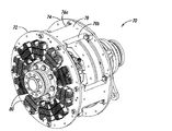
可変速度磁気駆動システムは、モータからのトルクを、エアギャップを横切って負荷に伝達することによって動作する。機器の駆動側と被駆動側との間に機械的な接続部はない。トルクは、駆動装置の一方の側の強力な希土類磁石と、他方の側の誘導される磁場との相互作用によって生成される。エアギャップの間隔を変えることによって、伝達されるトルクの量を制御でき、したがって速度制御を可能にする。 Variable speed magnetic drive systems operate by transmitting torque from the motor across the air gap to the load. There is no mechanical connection between the drive side and the driven side of the device. Torque is generated by the interaction of a strong rare earth magnet on one side of the drive and an induced magnetic field on the other side. By changing the air gap spacing, the amount of torque transmitted can be controlled, thus allowing speed control.
従来から、このタイプの可変速度駆動装置は、3組の構成部材からなる。希土類磁石を含む磁気ロータアセンブリが負荷に取り付けられる。導体ロータアセンブリがモータに取り付けられる。導体ロータアセンブリは、アルミニウム、銅、真鍮等の導電材料から作られるロータを含む。作動構成部材が、磁気ロータと導体ロータとの間のエアギャップの間隔を制御する。導体ロータアセンブリ及び磁気ロータアセンブリの相対回転は、エアギャップを横切って強力な磁気結合を誘導する。磁気ロータと導体ロータとの間のエアギャップの間隔を変えることによって、出力速度が制御される。出力速度は調整可能であり、制御可能であり、再現可能である。 Conventionally, this type of variable speed drive device consists of three sets of components. A magnetic rotor assembly including a rare earth magnet is attached to the load. A conductor rotor assembly is attached to the motor. The conductor rotor assembly includes a rotor made from a conductive material such as aluminum, copper, brass. Actuating components control the spacing of the air gap between the magnetic rotor and the conductor rotor. The relative rotation of the conductor rotor assembly and the magnetic rotor assembly induces strong magnetic coupling across the air gap. By changing the spacing of the air gap between the magnetic rotor and the conductor rotor, the output speed is controlled. The output speed is adjustable, controllable and reproducible.
磁気誘導の原理は、磁石と導体との間の相対運動を必要とする。これは、出力速度が入力速度より常に低いことを意味する。速度の差は、すべりとして既知である。通常、全定格モータ速度における動作中のすべりは1%−3%である。 The principle of magnetic induction requires relative movement between the magnet and the conductor. This means that the output speed is always lower than the input speed. The difference in speed is known as slip. Typically, the slip during operation at full rated motor speed is 1% -3%.
導体ロータに対する磁石の相対運動によって、導体材料において渦電流が誘導される。渦電流はさらにそれ自身の磁場を生成する。トルクを磁気ロータから導体ロータに伝えることを可能にするのは、永久磁場と、誘導された渦電流の磁場との相互作用である。導体材料における渦電流は、導体材料における電気的な加熱を生じる。 The relative movement of the magnet with respect to the conductor rotor induces eddy currents in the conductor material. Eddy currents also generate their own magnetic field. It is the interaction between the permanent magnetic field and the magnetic field of the induced eddy current that allows torque to be transferred from the magnetic rotor to the conductor rotor. Eddy currents in the conductor material cause electrical heating in the conductor material.
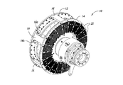
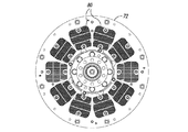
従来から、駆動ユニットの動作中の熱の除去を助けるために、導体ロータの外面にフィンが配置される。図1及び図2は、1つのそのような従来の構成を示している。
可変速度駆動装置10は、スペーサ16によってともに連結される導体ロータ12及び14を含む。複数の伝熱部材20が導体ロータ12及び14の外面に周方向に配列される。図2A−図2Cに示されているように、各伝熱部材20は複数のフィン26を含み、複数のフィン26はベース22から延在してフィン26間に複数のチャネル28を画成する。伝熱部材20は、ベース22の開口24を介して導体ロータ12及び14に固定できる。伝熱部材20は、フィン26及びチャネル28が導体ロータ12及び14の回転軸に対し略径方向に延在するように、導体ロータ12及び14に連結される。可変速度駆動装置10が動作すると、ロータ12及び14の回転によって空気がチャネル28を通って径方向外方に流れ、それによって導体ロータ12及び14を冷却する。
Conventionally, fins are placed on the outer surface of the conductor rotor to help remove heat during operation of the drive unit. 1 and 2 show one such conventional configuration.
The
可変速度駆動装置の導体ロータにヒートシンクアセンブリを含めることによって、動作中に許容できない量の騒音が発生することが確認されている。 Inclusion of a heat sink assembly in the conductor rotor of a variable speed drive has been found to generate unacceptable amounts of noise during operation.
前記課題を解決する手段の一つは、導体ロータアセンブリ及び磁気ロータアセンブリの相対回転によって動作可能な可変速度磁気駆動ユニット用のヒートシンク部材であって、前記導体ロータアセンブリに連結される寸法及び形状の取り付け面と、反対側にある対流伝熱面とを有するベース部分と、前記ベース部分の前記対流伝熱面から延在する複数の群のフィンであって、当該複数の群の各々における隣り合うフィンどうしが当該フィンの長尺方向に沿って延在するチャネルによって隔てられるとともに、当該複数の群どうしが前記長尺方向に対し略横断方向に延在する少なくとも1つのスロットによって隔てられる複数の群のフィンと、を備えている。
また、各群における前記フィンの高さは、当該群の中で互いに異なるものであってもよい。
さらに、前記フィンの高さは、前記ヒートシンク部材の中心線に向かって線形に高くなるテント状をなす外形を形成するものであってもよい。
あるいは、各群における前記フィンの高さは、当該群の中で互いに異なり、非線形の湾曲した外形を形成するものであってもよい。
あるいは、前記複数の群のフィンは、前記長尺方向に対し略横断方向に延在する2つより多くのスロットによって互いに隔てられるものであってもよい。
ヒートシンク上のフィンの高さを低減することによって、可変速度駆動装置のより低い速度の動作の場合は雑音レベルを許容可能な範囲まで低減できることが確認されている。また、フィン及びヒートシンク部材を横切るスロットを含めることによっても、高速の動作を含め、雑音レベルの低減に好ましい効果があることも確認されている。
One means for solving the above problem is a heat sink member for a variable speed magnetic drive unit operable by relative rotation of the conductor rotor assembly and the magnetic rotor assembly, the size and shape of the heat sink member being connected to the conductor rotor assembly. A base portion having a mounting surface and a convection heat transfer surface on the opposite side; and a plurality of groups of fins extending from the convection heat transfer surface of the base portion, adjacent to each other in the plurality of groups A plurality of groups in which the fins are separated by a channel extending along the longitudinal direction of the fins, and the groups are separated by at least one slot extending in a direction substantially transverse to the longitudinal direction And fins.
Moreover, the heights of the fins in each group may be different from each other in the group.
Furthermore, the height of the fin may form a tent-shaped outer shape that increases linearly toward the center line of the heat sink member.
Alternatively, the heights of the fins in each group may be different from each other in the group and form a nonlinear curved outer shape.
Alternatively, the plurality of groups of fins may be separated from each other by more than two slots extending in a direction substantially transverse to the longitudinal direction.
It has been found that by reducing the fin height on the heat sink, the noise level can be reduced to an acceptable range for lower speed operation of the variable speed drive. It has also been confirmed that the inclusion of a slot across the fin and heat sink member also has a positive effect on noise level reduction, including high speed operation.
前記課題を解決する手段のもう一つは、磁気ロータアセンブリと、前記磁気ロータアセンブリに対し、当該磁気ロータアセンブリとの間にエアギャップを有するとともに、当該磁気ロータアセンブリとの相対回転によって前記エアギャップを横切る磁気結合を誘導するように位置する導体ロータアセンブリと、前記導体アセンブリに連結されるとともに、当該導体アセンブリの回転軸の径方向に対し略横断方向に延在する少なくとも1つのスロットで互いに隔てられつつ、当該導体アセンブリの当該回転軸の略周方向に沿って配列された複数の群のフィンを有するヒートシンクアセンブリと、を備えた可変速度磁気駆動ユニットである。
また、前記ヒートシンクアセンブリは、前記導体ロータアセンブリの外面に配置される複数のヒートシンク部材を有し、当該複数のヒートシンク部材における各ヒートシンク部材は、前記複数の群のフィンを有するものであってもよい
さらに、前記ヒートシンクアセンブリは少なくとも1つのヒートシンクアセンブリであって、当該少なくとも1つのヒートシンクアセンブリにおける前記複数の群のフィンの各群における前記フィンの高さは、当該群の中で互いに異なるものであってもよい。
またさらに、前記少なくとも1つのヒートシンクアセンブリにおける前記フィンはテント状をなす外形を画成するものであってもよい。
あるいは、前記少なくとも1つのヒートシンクアセンブリにおける前記フィンは湾曲した外形を画成するものであってもよい。
あるいは、前記複数のヒートシンク部材における各ヒートシンク部材は、前記径方向に対し略横断方向に延在する2つより多くのスロットを有するものであってもよい。
Another means for solving the above problem is that the magnetic rotor assembly has an air gap between the magnetic rotor assembly and the magnetic rotor assembly, and the air gap is provided by relative rotation with the magnetic rotor assembly. A conductor rotor assembly positioned to induce a magnetic coupling across the conductor, and separated from each other by at least one slot coupled to the conductor assembly and extending generally transverse to the radial direction of the axis of rotation of the conductor assembly And a heat sink assembly having a plurality of groups of fins arranged along a substantially circumferential direction of the rotating shaft of the conductor assembly.
The heat sink assembly may include a plurality of heat sink members disposed on an outer surface of the conductor rotor assembly, and each heat sink member in the plurality of heat sink members may include the plurality of groups of fins. Further, the heat sink assembly is at least one heat sink assembly, and the heights of the fins in each group of the plurality of groups of fins in the at least one heat sink assembly are different from each other in the group. Also good.
Still further, the fins in the at least one heat sink assembly may define a tent-shaped outer shape.
Alternatively, the fins in the at least one heat sink assembly may define a curved profile.
Alternatively, each heat sink member in the plurality of heat sink members may have more than two slots extending in a direction substantially transverse to the radial direction.
前記課題を解決する手段のさらにもう一つは、導体ロータアセンブリ及び磁気ロータアセンブリの相対回転によって動作可能な可変速度磁気駆動ユニットによって発生する騒音を低減する、可変速度磁気駆動ユニットの騒音低減方法であって、前記導体ロータアセンブリの回転軸に対し略径方向に延在する第1の複数フィンを有する第1のヒートシンク部材を当該導体ロータアセンブリから取り外す工程と、次に、前記導体ロータアセンブリの回転軸に対し略径方向に延在して、露出総表面積が前記第1の複数フィンより小さい第2の複数フィンを有する第2のヒートシンク部材を、前記第1のヒートシンク部材の代わりに、前記導体ロータアセンブリに連結する工程と、を備えている。
また、前記第1の複数フィンの平均的な高さは、前記第2の複数フィンの平均的な高さより高いものであってもよい。
あるいは、前記第1の複数フィンは、前記第1のヒートシンク部材において径方向に中断されることなく延在し、前記第2の複数フィンは、前記径方向に対し略横断方向に延在するとともに当該第2の複数フィンを少なくとも2つの径方向の群に隔てる少なくとも1つのスロットを有するものであってもよい。
また、第1の複数フィンの平均的な高さは、前記第2の複数フィンの平均的な高さと略同じであることとしてもよい。
Still another means for solving the above problem is a noise reduction method for a variable speed magnetic drive unit that reduces noise generated by a variable speed magnetic drive unit operable by relative rotation of the conductor rotor assembly and the magnetic rotor assembly. Removing a first heat sink member having a first plurality of fins extending in a substantially radial direction with respect to a rotation axis of the conductor rotor assembly from the conductor rotor assembly, and then rotating the conductor rotor assembly A second heat sink member extending in a substantially radial direction with respect to the shaft and having a second plurality of fins whose exposed total surface area is smaller than the first plurality of fins is used instead of the first heat sink member. Connecting to the rotor assembly.
The average height of the first plurality of fins may be higher than the average height of the second plurality of fins.
Alternatively, the first plurality of fins extends in the first heat sink member without being interrupted in the radial direction, and the second plurality of fins extend in a direction substantially transverse to the radial direction. It may have at least one slot separating the second plurality of fins into at least two radial groups.
The average height of the first plurality of fins may be substantially the same as the average height of the second plurality of fins.
図面において、同一の参照符号は同様の部材又は作用を示す。 In the drawings, the same reference numerals indicate similar members or actions.
以下の説明において、本発明の種々の実施形態の完全な理解を提供するために或る特定の詳細が記載される。しかし、当業者は、本発明をこれらの詳細を用いることなく実施できることを理解するであろう。 In the following description, certain specific details are set forth in order to provide a thorough understanding of various embodiments of the invention. However, one skilled in the art will understand that the invention may be practiced without these details.
文脈によって別途要求されない限り、本明細書及び以下の特許請求の範囲を通して、「備える」という用語及びその変化形は、包括的にオープンエンドに、すなわち、「−を含むがそれらに限定されない」として解釈されるべきである。 Unless otherwise required by context, throughout this specification and the following claims, the term “comprising” and variations thereof are generically open-ended, ie, “including but not limited to”. Should be interpreted.
本明細書を通して、「1つの実施形態」又は「一実施形態」への言及は、実施形態に関連して記載される特定の特徴、構造又は特性が少なくとも1つの実施形態に含まれることを意味する。したがって、本明細書を通じた種々の箇所における「1つの実施形態では」又は「一実施形態では」という表現の出現は、必ずしも全てが同じ実施形態に言及するものではない。さらに、特定の特徴、構造又は特性を、1つ又は複数の実施形態において任意の好適な方法で組み合わせることができる。 Throughout this specification, reference to “an embodiment” or “an embodiment” means that the particular feature, structure, or characteristic described in connection with the embodiment is included in at least one embodiment. To do. Thus, the appearances of the phrases “in one embodiment” or “in one embodiment” in various places throughout this specification are not necessarily all referring to the same embodiment. Furthermore, the particular features, structures, or characteristics may be combined in any suitable manner in one or more embodiments.
本明細書及び添付の特許請求の範囲において用いられる場合、単数形(”a,” ”an,” ”the”)は、内容によって別途はっきりと指示されない限り、複数の指示対象を含む。「又は」という用語は概してその最も広範な意味で使用され、すなわち、内容によって別途はっきりと指示されない限り、「及び/又は」を意味するものとして使用されることにも留意されたい。 As used in this specification and the appended claims, the singular forms “a,” “an,” “the”) include plural referents unless the content clearly dictates otherwise. It should also be noted that the term “or” is generally used in its broadest sense, ie, used to mean “and / or” unless the content clearly dictates otherwise.
本明細書において提供される開示の要約書は、専ら便宜的なものであり、実施形態の範囲又は意味を説明するものではない。 The abstract of the disclosure provided herein is for convenience only and does not describe the scope or meaning of the embodiments.
上述したように、可変速度駆動装置におけるヒートシンクは、可変速度駆動装置の閾値回転速度を超えると望ましくない大きなヒューヒューという騒音を生じる可能性があることが認識されている。幾つかのヒートシンクの外形の評価によって、ヒューヒューという騒音が、ヒートシンクのフィンの高さ、長さ、及び可変速度駆動装置の回転速度に応じて変わることが明らかとなった。
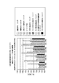
図3は、900回転毎分(rpm)、1200rpm、1500rpm、及び1800rpmで、ヒートシンクなし及び様々なヒートシンク構成を用いて動作した場合の、可変速度駆動装置の一方の側から発生する雑音のレベルを示している。
As mentioned above, it has been recognized that heat sinks in variable speed drives can cause undesirable loud noise when the threshold rotational speed of the variable speed drive is exceeded. Evaluation of several heat sink outlines revealed that the noise of fusing varied depending on the height and length of the fins of the heat sink and the rotational speed of the variable speed drive.
FIG. 3 shows the level of noise generated from one side of the variable speed drive when operating at 900 revolutions per minute (rpm), 1200 rpm, 1500 rpm, and 1800 rpm with no heat sink and various heat sink configurations. Show.
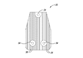
全値高のヒートシンク、半値高のヒートシンク、及び3分の1値高のヒートシンクを含む、種々のヒートシンクの高さを試験した。図2及び図4は、全値高のヒートシンク及び半値高のヒートシンクの例をそれぞれ示している。
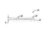
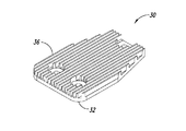
図2A−図2Cにおけるヒートシンク20のフィン26のそれぞれは、ベース22の上に約0.80インチの高さHを有する。図4A−図4Cに示されているヒートシンク30は、複数のフィン36を含むベース32を含む。フィン36は、約0.40インチである高さh、すなわち、図2A−図2Cに示されているヒートシンク20の高さHの半分の高さを有する。フィン36は、ヒートシンク部材30内にチャネル38を画成する。ヒートシンク部材30は、ベース32の孔34を介して導体ロータに固定できる。
Various heat sink heights were tested, including full-height heat sinks, half-height heat sinks, and one-third high heat sinks. 2 and 4 show examples of a full-value heat sink and a half-value heat sink, respectively.
Each of the
図3に示されているように、ヒートシンクのフィンの高さを低下させることによって、低速における動作の場合は騒音の発生が大幅に低減される。例えば、900rpm及び1200rpmで動作する可変速度駆動装置における半分の高さのヒートシンク構成によって発生する騒音の量は、いずれのヒートシンクも有しない可変速度駆動装置によって発生した騒音と同等であった。
しかし、速度が1500rpmまで上昇すると、半分のヒートシンク構成によって発生した騒音は、ヒートシンクがない場合の80デシベル未満及び全値高のヒートシンクの場合の100デシベル超に比して、90デシベル超に増大した。速度が1800rpmまで上昇すると、半分のヒートシンク構成によって発生した騒音は、全値高のヒートシンクによって発生した騒音の5デシベル以内であり、ヒートシンクを有しない駆動ユニットによって発生した騒音より約15デシベル高かった。特に、騒音の利点は、全値高のヒートシンクの3分の1値高であるヒートシンクに関して試験した各動作速度にわたって持続した。
As shown in FIG. 3, reducing the height of the heat sink fins greatly reduces the generation of noise when operating at low speeds. For example, the amount of noise generated by a half-height heat sink configuration in a variable speed drive operating at 900 rpm and 1200 rpm was equivalent to the noise generated by a variable speed drive without any heat sink.
However, as the speed increased to 1500 rpm, the noise generated by the half heat sink configuration increased to over 90 decibels compared to less than 80 decibels without a heat sink and over 100 decibels with a full heat sink. . As the speed increased to 1800 rpm, the noise generated by the half heat sink configuration was within 5 decibels of the noise generated by the full heat sink, and about 15 decibels higher than the noise generated by the drive unit without the heat sink. In particular, the noise benefit persisted over each operating speed tested for heat sinks that were one third higher than the full heat sink.
テント状をなす外形を有するヒートシンクも試験した。これらのヒートシンクは、各ヒートシンクの中で可変のフィン高を有する。フィン高は、ヒートシンクの一方の側から、中央の最大値フィン高まで線形に増大し、次に、ヒートシンクの他方の側まで線形に低減する。結果として生じる外形はテントに似ている。
図3に示されているように、テント状をなす外形のヒートシンクは、900rpm、1200rpm、及び1500rpmの場合に半値高のヒートシンクほど大きな騒音の低減を達成せず、1800rpmでは半分値高のヒートシンクの騒音低減と同等であった。
A heat sink having a tent-shaped profile was also tested. These heat sinks have variable fin heights within each heat sink. The fin height increases linearly from one side of the heat sink to the central maximum fin height and then decreases linearly to the other side of the heat sink. The resulting profile resembles a tent.
As shown in FIG. 3, the tent-shaped heat sink does not achieve as much noise reduction as half-height heat sinks at 900 rpm, 1200 rpm, and 1500 rpm, and half-height heat sinks at 1800 rpm. It was equivalent to noise reduction.
予想外に、可変速度駆動装置によって発生する雑音レベルを、単にヒートシンクのフィンを横切って横断方向スロットを含むことによって、ヒートシンクの高さを低減することなく大幅に低減できることが更に確認された。
図3に示されているように、スロット付きのヒートシンクの騒音の利点は、スロット付きの全値高のヒートシンク、スロットを含むテント状のヒートシンク、及び、スロットを含む半値高のヒートシンクの場合に、可変速度駆動装置の速度が900rpmから1800rpmに上昇しても持続した。
Unexpectedly, it has further been found that the noise level generated by the variable speed drive can be significantly reduced without reducing the height of the heat sink by simply including a transverse slot across the fin of the heat sink.
As shown in FIG. 3, the noise benefits of a slotted heat sink are: a full-height heat sink with a slot, a tent-shaped heat sink with a slot, and a half-height heat sink with a slot. It persisted even when the speed of the variable speed drive increased from 900 rpm to 1800 rpm.
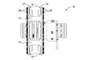
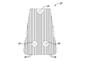
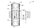
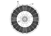
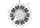
図5A−図5Dは、スロット付きの全値高のヒートシンク60を含む可変速度駆動装置50を示している。可変速度駆動装置50は、スペーサ56を介して連結される2つの導体ロータ52及び54を含む。導体ロータ52及び54は、アルミニウム、銅又は真鍮等の導電材料から作られるロータを含む。
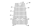
図6A−図6Cは、スロット付きのヒートシンク部材60をより詳細に示している。各ヒートシンク部材60はベース62を含み、ベース62から複数のフィン66が延在する。フィン66は、それらの間にチャネル68を画成し、ベース62の上に全値高Hだけ延在する。伝熱部材60は、フィン66の延在方向に対し略横断方向に延在する複数のスロット67を更に含み、それによって、フィンを、導体ロータの回転軸に対し径方向に複数の群に分ける。伝熱部材60は、取り付け孔64を介して導体ロータ52及び54に固着できる。
FIGS. 5A-5D show a
6A-6C show the slotted
導体ロータ52及び54を連結するスペーサ部材56の形状を変えることによって、騒音の低減を同様に得ることができることが更に確認された。具体的には、図5Aに示されているように、各スペーサ56は、その前縁及び後縁にアール56a及び56bを含む。対照的に、図1Aに示されているように、スペーサ16は、その前縁及び後縁に急峻な縁16a及び16bを含む。
It has further been confirmed that noise reduction can be obtained as well by changing the shape of the
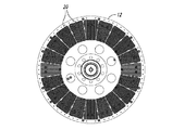
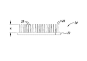
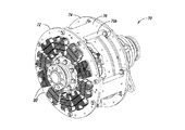
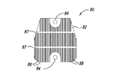
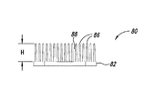
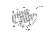
ヒートシンク伝達部材において用いられるスロットの数を、可変速度駆動装置の寸法に応じて変えることができることが更に確認された。図7A−図7Dは、本開示の別の態様による可変速度駆動装置を示している。可変速度駆動装置70は、前縁76a及び後縁76bを有するスペーサ76によって連結される導体ロータ部材72及び74を含む。伝熱部材80が、導体ロータ部材72及び74の反対側の面に固着される。
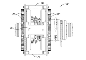
図8A−図8Cは、伝熱部材80をより詳細に示している。各伝熱部材80はベース82を含み、ベース82からフィン86が高さHまで延在する。フィン86は複数のチャネル88を画成する。2つのスロット87がフィン86を横断する。伝熱部材80は、ベース82の取り付け支柱84を介して導体ロータ72又は74に固定できる。
It was further confirmed that the number of slots used in the heat sink transmission member can be varied depending on the dimensions of the variable speed drive. 7A-7D illustrate a variable speed drive according to another aspect of the present disclosure. The
8A-8C show the
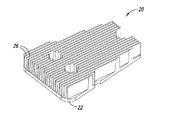
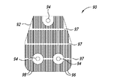
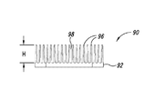
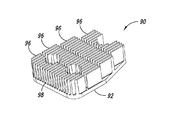
図9A−図9Cは、3つの横断方向スロットを含む伝熱部材を示している。伝熱部材90はベース92を含み、ベース92からはフィン96が高さhまで延在する。フィン96はチャネル98を画成する。横断方向スロット97は複数のフィンを4つの群に分ける。伝熱部材90は、ベース92の取り付け孔94を介して導体ロータ部材に固定できる。
9A-9C show a heat transfer member that includes three transverse slots. The
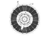
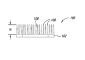
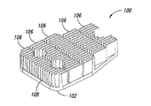
図10A−図10Cは、4つの横断方向スロット107を含む伝熱部材100を示している。横断方向スロット107は、ベース102から延在する複数の群のフィン106を分けるとともに隔てる。フィンは高さHに達する。伝熱部材100は、ベース102の取り付け孔104を介して回転導電部材に固着できる。
10A-10C illustrate a
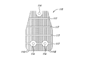
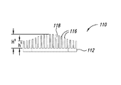
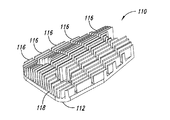
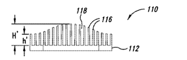
図11A−図11Cは、本開示の別の態様による伝熱部材110を示している。フィン116がベース112から延在する。フィン116は間にチャネル118を画成する。スロット117がフィン116を複数の群に分けるとともに隔てる。ベース112は、伝熱部材を導体ロータに固定するために取り付け孔114を含む。
前述の例とは異なり、フィン116の高さは、湾曲した外形を形成するように多様に変化するように分布する。特に、図11Bに示されているように、フィンは、最小値高さh’から最大値高さH’まで非線形に変化するように分布する。
11A-11C illustrate a
Unlike the previous example, the height of the
新たな設置に加えて、既存の伝熱部材を、本明細書において記載される改良された伝熱部材のいずれかと交換することによって騒音の改善を達成できる。例えば、低速用途では全値高の伝熱部材の代わりに半値高の伝熱部材を用いることができる。より高速の用途では、全値高の伝熱部材の代わりに、所望の伝熱に必要な適切な高さを有するスロット付きの伝熱部材を用いることができる。 In addition to new installations, noise improvements can be achieved by replacing existing heat transfer members with any of the improved heat transfer members described herein. For example, in a low-speed application, a heat transfer member with a half value height can be used instead of a heat transfer member with a full value. For higher speed applications, a slotted heat transfer member having the appropriate height required for the desired heat transfer can be used instead of the full value heat transfer member.
上述した種々の実施形態を組み合わせて更なる実施形態を提供できる。上記で詳述した説明を踏まえてこれら及び他の変更を実施形態に対して行うことができる。概して、以下の特許請求の範囲で使用される用語は、請求項を、明細書及び特許請求の範囲において開示される特定の実施形態に限定するように解釈されるべきではなく、そのような特許請求の範囲に権利が与えられる均等物の全範囲とともに全ての可能な実施形態を含むように解釈されるべきである。したがって、特許請求の範囲は本開示によって限定されない。 The various embodiments described above can be combined to provide further embodiments. These and other changes can be made to the embodiments in light of the above detailed description. In general, the terms used in the following claims should not be construed to limit the claims to the specific embodiments disclosed in the specification and the claims, such patents. It should be construed to include all possible embodiments with the full scope of equivalents to which the claims are entitled. Accordingly, the claims are not limited by the disclosure.
全値高のヒートシンク、半値高のヒートシンク、及び3分の1値高のヒートシンクを含む、種々のヒートシンクの高さを試験した。図2及び図4は、全値高のヒートシンク及び半値高のヒートシンクの例をそれぞれ示している。
図2A−図2Cにおけるヒートシンク20のフィン26のそれぞれは、ベース22の上に約0.80インチの高さHを有する。図4A−図4Cに示されているヒートシンク30は、複数のフィン36が延在するベース32を含む。フィン36は、約0.40インチである高さh、すなわち、図2A−図2Cに示されているヒートシンク20の高さHの半分の高さを有する。フィン36は、ヒートシンク部材30内にチャネル38を画成する。ヒートシンク部材30は、ベース32の孔34を介して導体ロータに固定できる。
Various heat sink heights were tested, including full-height heat sinks, half-height heat sinks, and one-third high heat sinks. 2 and 4 show examples of a full-value heat sink and a half-value heat sink, respectively.
Each of the
ヒートシンク伝達部材において用いられるスロットの数を、可変速度駆動装置の寸法に応じて変えることができることが更に確認された。図7A−図7Dは、本開示の別の態様による可変速度駆動装置を示している。可変速度駆動装置70は、前縁76a及び後縁76bを有するスペーサ76によって連結される導体ロータ部材72及び74を含む。伝熱部材80が、導体ロータ部材72及び74の反対側の面に固着される。
図8A−図8Cは、伝熱部材80をより詳細に示している。各伝熱部材80はベース82を含み、ベース82からフィン86が高さHまで延在する。フィン86は複数のチャネル88を画成する。2つのスロット87がフィン86を横断する。伝熱部材80は、ベース82の取り付け孔84を介して導体ロータ72又は74に固定できる。
It was further confirmed that the number of slots used in the heat sink transmission member can be varied depending on the dimensions of the variable speed drive. 7A-7D illustrate a variable speed drive according to another aspect of the present disclosure. The
8A-8C show the
Claims (17)
前記導体ロータアセンブリに連結される寸法及び形状の取り付け面と、反対側にある対流伝熱面とを有するベース部分と、
前記ベース部分の前記対流伝熱面から延在する複数の群のフィンであって、当該複数の群の各々における隣り合うフィンどうしが当該フィンの長尺方向に沿って延在するチャネルによって隔てられるとともに、当該複数の群どうしが前記長尺方向に対し略横断方向に延在する少なくとも1つのスロットによって隔てられる複数の群のフィンと、
を備えたことを特徴とするヒートシンク部材。 A heat sink member for a variable speed magnetic drive unit operable by relative rotation of a conductor rotor assembly and a magnetic rotor assembly comprising:
A base portion having a dimensioned and shaped mounting surface coupled to the conductor rotor assembly and a convective heat transfer surface on the opposite side;
A plurality of groups of fins extending from the convective heat transfer surface of the base portion, wherein adjacent fins in each of the plurality of groups are separated by a channel extending along the longitudinal direction of the fins. And a plurality of groups of fins separated by at least one slot extending between the plurality of groups in a direction substantially transverse to the longitudinal direction;
A heat sink member comprising:
前記磁気ロータアセンブリに対し、当該磁気ロータアセンブリとの間にエアギャップを有するとともに、当該磁気ロータアセンブリとの相対回転によって前記エアギャップを横切る磁気結合を誘導するように位置する導体ロータアセンブリと、
前記導体アセンブリに連結されるとともに、当該導体アセンブリの回転軸の径方向に対し略横断方向に延在する少なくとも1つのスロットで互いに隔てられつつ、当該導体アセンブリの当該回転軸の略周方向に沿って配列された複数の群のフィンを有するヒートシンクアセンブリと、
を備えたことを特徴とする可変速度磁気駆動ユニット。 A magnetic rotor assembly;
A conductor rotor assembly having an air gap with respect to the magnetic rotor assembly and positioned to induce a magnetic coupling across the air gap by relative rotation with the magnetic rotor assembly;
The conductor assembly is coupled to the conductor assembly and separated from each other by at least one slot extending in a direction substantially transverse to the radial direction of the rotation axis of the conductor assembly, and along the substantially circumferential direction of the rotation axis of the conductor assembly. A heat sink assembly having a plurality of groups of fins arranged in a row;
A variable speed magnetic drive unit comprising:
前記導体ロータアセンブリの回転軸に対し略径方向に延在する第1の複数フィンを有する第1のヒートシンク部材を当該導体ロータアセンブリから取り外す工程と、
次に、前記導体ロータアセンブリの回転軸に対し略径方向に延在して、露出総表面積が前記第1の複数フィンより小さい第2の複数フィンを有する第2のヒートシンク部材を、前記第1のヒートシンク部材の代わりに、前記導体ロータアセンブリに連結する工程と、
を備えたことを特徴とする、可変速度磁気駆動ユニットの騒音低減方法。 A noise reduction method for a variable speed magnetic drive unit that reduces noise generated by a variable speed magnetic drive unit operable by relative rotation of a conductor rotor assembly and a magnetic rotor assembly, comprising:
Removing from the conductor rotor assembly a first heat sink member having a first plurality of fins extending in a substantially radial direction with respect to the rotational axis of the conductor rotor assembly;
Next, a second heat sink member having a second plurality of fins extending in a substantially radial direction with respect to the rotation axis of the conductor rotor assembly and having an exposed total surface area smaller than the first plurality of fins, Connecting to the conductor rotor assembly instead of the heat sink member of
A noise reduction method for a variable speed magnetic drive unit.
Applications Claiming Priority (3)
| Application Number | Priority Date | Filing Date | Title |
|---|---|---|---|
| US201361770003P | 2013-02-27 | 2013-02-27 | |
| US61/770,003 | 2013-02-27 | ||
| PCT/US2014/016327 WO2014133780A1 (en) | 2013-02-27 | 2014-02-13 | Apparatus, systems and methods for reducing noise generated by rotating couplings |
Publications (1)
| Publication Number | Publication Date |
|---|---|
| JP2016508024A true JP2016508024A (en) | 2016-03-10 |
Family
ID=50190803
Family Applications (1)
| Application Number | Title | Priority Date | Filing Date |
|---|---|---|---|
| JP2015558883A Pending JP2016508024A (en) | 2013-02-27 | 2014-02-13 | Apparatus, system, and method for reducing noise generated by rotational coupling |
Country Status (13)
| Country | Link |
|---|---|
| US (1) | US20140239762A1 (en) |
| EP (1) | EP2962384A1 (en) |
| JP (1) | JP2016508024A (en) |
| KR (1) | KR20150122157A (en) |
| CN (1) | CN105027401A (en) |
| AR (1) | AR094916A1 (en) |
| AU (1) | AU2014223914A1 (en) |
| BR (1) | BR112015020206A2 (en) |
| CA (1) | CA2899035A1 (en) |
| IL (1) | IL240254A0 (en) |
| MX (1) | MX2015010405A (en) |
| TW (1) | TW201503550A (en) |
| WO (1) | WO2014133780A1 (en) |
Families Citing this family (3)
| Publication number | Priority date | Publication date | Assignee | Title |
|---|---|---|---|---|
| EP3125409A1 (en) * | 2015-07-29 | 2017-02-01 | Goodrich Actuation Systems Ltd. | Extruded housing for electric motor |
| CN107394988B (en) * | 2017-09-19 | 2019-11-26 | 安徽沃弗电力科技有限公司 | A kind of magnetic coupling heat sink |
| CN116317317B (en) * | 2023-05-17 | 2023-07-25 | 佛山市顺德龙佳微电机实业有限公司 | Low-noise direct-current permanent magnet motor and juicer |
Family Cites Families (18)
| Publication number | Priority date | Publication date | Assignee | Title |
|---|---|---|---|---|
| JPS6014498A (en) * | 1983-07-06 | 1985-01-25 | 日本電気株式会社 | Forcible air cooling heat sink unit |
| US5542176A (en) * | 1992-09-21 | 1996-08-06 | Hideaki Serizawa | Radiation plate and method of producing the same |
| US5834872A (en) * | 1993-05-21 | 1998-11-10 | Magna Force, Inc. | Adjustable magnetic coupler |
| DE4427426A1 (en) * | 1993-11-05 | 1995-05-11 | Horng Ching Shen | Motor having an arrangement for heat dissipation |
| US5709263A (en) * | 1995-10-19 | 1998-01-20 | Silicon Graphics, Inc. | High performance sinusoidal heat sink for heat removal from electronic equipment |
| US5740014A (en) * | 1996-12-11 | 1998-04-14 | Lin; Chun Sheng | CPU heat sink |
| TW556074B (en) * | 1998-12-15 | 2003-10-01 | Foxconn Prec Components Co Ltd | Heat sink and the manufacturing method thereof |
| FR2805121B1 (en) * | 2000-02-11 | 2002-04-26 | Leroy Somer | MODULAR CONVERTER |
| US7021365B2 (en) * | 2002-08-15 | 2006-04-04 | Valere Power, Inc. | Component to heat sink spring clip method and apparatus |
| US20050167082A1 (en) * | 2004-01-30 | 2005-08-04 | Datech Technology Co., Ltd. | Heat sink-type cooling device for an integrated circuit |
| CN101604878B (en) * | 2008-06-10 | 2012-01-25 | 中山大洋电机股份有限公司 | Motor end cover and applied motor thereof |
| JP4943398B2 (en) * | 2008-09-16 | 2012-05-30 | 新日本製鐵株式会社 | Heat sink |
| JP4907694B2 (en) * | 2009-05-13 | 2012-04-04 | 三菱電機株式会社 | Rotating electric machine |
| CN101997391B (en) * | 2009-08-11 | 2012-09-05 | 林贵生 | Transmission shaft permanent magnet coupling drive and speed regulation device capable of adjusting magnetic torque |
| CH703820A1 (en) * | 2010-09-21 | 2012-03-30 | Alstom Hydro France | AIR-COOLED GENERATOR. |
| CN102455763A (en) * | 2010-10-27 | 2012-05-16 | 鸿富锦精密工业(深圳)有限公司 | Heat radiator fixing device combination |
| US20130032323A1 (en) * | 2011-08-02 | 2013-02-07 | Hsu Takeho | Heat sink structure |
| CN103701295B (en) * | 2013-11-29 | 2016-08-17 | 迈格钠磁动力股份有限公司 | A kind of noise reduction heat dissipation element and magnetic motive force drive |
-
2014
- 2014-02-13 CN CN201480010445.6A patent/CN105027401A/en active Pending
- 2014-02-13 US US14/180,061 patent/US20140239762A1/en not_active Abandoned
- 2014-02-13 KR KR1020157023841A patent/KR20150122157A/en not_active Application Discontinuation
- 2014-02-13 AU AU2014223914A patent/AU2014223914A1/en not_active Abandoned
- 2014-02-13 WO PCT/US2014/016327 patent/WO2014133780A1/en active Application Filing
- 2014-02-13 BR BR112015020206A patent/BR112015020206A2/en not_active IP Right Cessation
- 2014-02-13 EP EP14707574.1A patent/EP2962384A1/en not_active Withdrawn
- 2014-02-13 JP JP2015558883A patent/JP2016508024A/en active Pending
- 2014-02-13 MX MX2015010405A patent/MX2015010405A/en unknown
- 2014-02-13 CA CA2899035A patent/CA2899035A1/en not_active Abandoned
- 2014-02-27 TW TW103106895A patent/TW201503550A/en unknown
- 2014-02-27 AR ARP140100627A patent/AR094916A1/en unknown
-
2015
- 2015-07-30 IL IL240254A patent/IL240254A0/en unknown
Also Published As
| Publication number | Publication date |
|---|---|
| KR20150122157A (en) | 2015-10-30 |
| CN105027401A (en) | 2015-11-04 |
| BR112015020206A2 (en) | 2017-07-18 |
| CA2899035A1 (en) | 2014-09-04 |
| IL240254A0 (en) | 2015-09-24 |
| TW201503550A (en) | 2015-01-16 |
| US20140239762A1 (en) | 2014-08-28 |
| MX2015010405A (en) | 2016-04-15 |
| WO2014133780A1 (en) | 2014-09-04 |
| AR094916A1 (en) | 2015-09-09 |
| EP2962384A1 (en) | 2016-01-06 |
| AU2014223914A1 (en) | 2015-08-13 |
Similar Documents
| Publication | Publication Date | Title |
|---|---|---|
| JP3504970B2 (en) | Stator lamination | |
| US7839043B2 (en) | Rotary structure of permanent magnet electric machinery and method for determining the structure thereof | |
| US20180195526A1 (en) | Serial axial flow fan | |
| EP3528367A1 (en) | Rotor structure, motor and compressor | |
| US9989072B2 (en) | Fan | |
| JP2005311343A5 (en) | ||
| US20180195525A1 (en) | Serial axial flow fan | |
| JP2016508024A (en) | Apparatus, system, and method for reducing noise generated by rotational coupling | |
| CN106340981B (en) | The cooling device of permanent magnetism temperature in a kind of reduction magneto | |
| US20140332194A1 (en) | Apparatus, systems and methods for reducing noise generated by rotating couplings and drives | |
| JP2015023680A (en) | Permanent magnet type motor | |
| JP2009027800A (en) | Cooling structure of motor | |
| JP4943398B2 (en) | Heat sink | |
| CN206302231U (en) | Rotor core, cage rotor and squirrel cage motor | |
| CN104578649A (en) | Axial direction sectional type motor rotor with arc-shaped air deflectors | |
| JP2004129407A (en) | Cooling structure for motor | |
| WO2021070823A1 (en) | Rotor for rotating electrical machine | |
| US6720700B2 (en) | Motor stator for a home electric fan | |
| US20170338720A1 (en) | Enhanced convective rotor cooling | |
| KR20090070193A (en) | Rotor for high speed permanent magnet machine | |
| JP2000337296A (en) | Blower device | |
| CN213402777U (en) | Permanent magnet coupler of radial airflow heat dissipation device | |
| JP6029689B2 (en) | Rotating electric machine | |
| JPWO2015186186A1 (en) | Rotating electrical machine rotor | |
| CN102536858A (en) | Fan |
Legal Events
| Date | Code | Title | Description |
|---|---|---|---|
| A521 | Request for written amendment filed |
Free format text: JAPANESE INTERMEDIATE CODE: A523 Effective date: 20150828 |