JP2016505108A - Purge and cooling air for the exhaust section of the gas turbine assembly - Google Patents
Purge and cooling air for the exhaust section of the gas turbine assembly Download PDFInfo
- Publication number
- JP2016505108A JP2016505108A JP2015553907A JP2015553907A JP2016505108A JP 2016505108 A JP2016505108 A JP 2016505108A JP 2015553907 A JP2015553907 A JP 2015553907A JP 2015553907 A JP2015553907 A JP 2015553907A JP 2016505108 A JP2016505108 A JP 2016505108A
- Authority
- JP
- Japan
- Prior art keywords
- purge air
- turbine
- casing
- cavity
- purge
- Prior art date
- Legal status (The legal status is an assumption and is not a legal conclusion. Google has not performed a legal analysis and makes no representation as to the accuracy of the status listed.)
- Granted
Links
Images


Classifications
-
- F—MECHANICAL ENGINEERING; LIGHTING; HEATING; WEAPONS; BLASTING
- F01—MACHINES OR ENGINES IN GENERAL; ENGINE PLANTS IN GENERAL; STEAM ENGINES
- F01D—NON-POSITIVE DISPLACEMENT MACHINES OR ENGINES, e.g. STEAM TURBINES
- F01D9/00—Stators
- F01D9/06—Fluid supply conduits to nozzles or the like
- F01D9/065—Fluid supply or removal conduits traversing the working fluid flow, e.g. for lubrication-, cooling-, or sealing fluids
-
- F—MECHANICAL ENGINEERING; LIGHTING; HEATING; WEAPONS; BLASTING
- F01—MACHINES OR ENGINES IN GENERAL; ENGINE PLANTS IN GENERAL; STEAM ENGINES
- F01D—NON-POSITIVE DISPLACEMENT MACHINES OR ENGINES, e.g. STEAM TURBINES
- F01D25/00—Component parts, details, or accessories, not provided for in, or of interest apart from, other groups
- F01D25/08—Cooling; Heating; Heat-insulation
- F01D25/12—Cooling
- F01D25/125—Cooling of bearings
-
- F—MECHANICAL ENGINEERING; LIGHTING; HEATING; WEAPONS; BLASTING
- F01—MACHINES OR ENGINES IN GENERAL; ENGINE PLANTS IN GENERAL; STEAM ENGINES
- F01D—NON-POSITIVE DISPLACEMENT MACHINES OR ENGINES, e.g. STEAM TURBINES
- F01D25/00—Component parts, details, or accessories, not provided for in, or of interest apart from, other groups
- F01D25/16—Arrangement of bearings; Supporting or mounting bearings in casings
- F01D25/162—Bearing supports
-
- F—MECHANICAL ENGINEERING; LIGHTING; HEATING; WEAPONS; BLASTING
- F01—MACHINES OR ENGINES IN GENERAL; ENGINE PLANTS IN GENERAL; STEAM ENGINES
- F01D—NON-POSITIVE DISPLACEMENT MACHINES OR ENGINES, e.g. STEAM TURBINES
- F01D25/00—Component parts, details, or accessories, not provided for in, or of interest apart from, other groups
- F01D25/30—Exhaust heads, chambers, or the like
-
- F—MECHANICAL ENGINEERING; LIGHTING; HEATING; WEAPONS; BLASTING
- F01—MACHINES OR ENGINES IN GENERAL; ENGINE PLANTS IN GENERAL; STEAM ENGINES
- F01D—NON-POSITIVE DISPLACEMENT MACHINES OR ENGINES, e.g. STEAM TURBINES
- F01D9/00—Stators
- F01D9/02—Nozzles; Nozzle boxes; Stator blades; Guide conduits, e.g. individual nozzles
-
- F—MECHANICAL ENGINEERING; LIGHTING; HEATING; WEAPONS; BLASTING
- F02—COMBUSTION ENGINES; HOT-GAS OR COMBUSTION-PRODUCT ENGINE PLANTS
- F02C—GAS-TURBINE PLANTS; AIR INTAKES FOR JET-PROPULSION PLANTS; CONTROLLING FUEL SUPPLY IN AIR-BREATHING JET-PROPULSION PLANTS
- F02C6/00—Plural gas-turbine plants; Combinations of gas-turbine plants with other apparatus; Adaptations of gas- turbine plants for special use
- F02C6/04—Gas-turbine plants providing heated or pressurised working fluid for other apparatus, e.g. without mechanical power output
- F02C6/06—Gas-turbine plants providing heated or pressurised working fluid for other apparatus, e.g. without mechanical power output providing compressed gas
- F02C6/08—Gas-turbine plants providing heated or pressurised working fluid for other apparatus, e.g. without mechanical power output providing compressed gas the gas being bled from the gas-turbine compressor
-
- F—MECHANICAL ENGINEERING; LIGHTING; HEATING; WEAPONS; BLASTING
- F02—COMBUSTION ENGINES; HOT-GAS OR COMBUSTION-PRODUCT ENGINE PLANTS
- F02C—GAS-TURBINE PLANTS; AIR INTAKES FOR JET-PROPULSION PLANTS; CONTROLLING FUEL SUPPLY IN AIR-BREATHING JET-PROPULSION PLANTS
- F02C7/00—Features, components parts, details or accessories, not provided for in, or of interest apart form groups F02C1/00 - F02C6/00; Air intakes for jet-propulsion plants
- F02C7/12—Cooling of plants
- F02C7/16—Cooling of plants characterised by cooling medium
- F02C7/18—Cooling of plants characterised by cooling medium the medium being gaseous, e.g. air
-
- F—MECHANICAL ENGINEERING; LIGHTING; HEATING; WEAPONS; BLASTING
- F05—INDEXING SCHEMES RELATING TO ENGINES OR PUMPS IN VARIOUS SUBCLASSES OF CLASSES F01-F04
- F05D—INDEXING SCHEME FOR ASPECTS RELATING TO NON-POSITIVE-DISPLACEMENT MACHINES OR ENGINES, GAS-TURBINES OR JET-PROPULSION PLANTS
- F05D2240/00—Components
- F05D2240/10—Stators
- F05D2240/15—Heat shield
Abstract
外側ケーシングと、内側ケーシングと、外側流路壁および内側流路壁の間に規定される環状の排気ガス経路と、ガス経路から半径方向外側および内側に配置されたタービン排気ケーシングキャビティと、を有するタービン排気ケーシングが開示される。複数の支柱構造が、内側ケーシングを外側ケーシングに対して支持させ、かつフェアリングは、外側および内側流路壁の間に広がる領域で各支柱を包囲する。第1のパージ空気経路が、パージ冷却空気を内側ケーシングへ向けて半径方向内側に誘導するために支柱の少なくとも1つを通って延在する。第2のパージ空気経路が、パージ冷却空気を半径方向外側へさらに誘導するために支柱を通って延在しており、排気ケーシングキャビティのうち外側流路壁から半径方向外側にある位置へ向けてパージ空気を流動させる。An outer casing; an inner casing; an annular exhaust gas path defined between the outer flow path wall and the inner flow path wall; and a turbine exhaust casing cavity disposed radially outward and inward from the gas path. A turbine exhaust casing is disclosed. A plurality of strut structures support the inner casing with respect to the outer casing, and the fairing surrounds each strut in an area that extends between the outer and inner channel walls. A first purge air path extends through at least one of the struts to direct purge cooling air radially inward toward the inner casing. A second purge air path extends through the struts to further guide purge cooling air radially outward and toward a position radially outward from the outer flow channel wall of the exhaust casing cavity. Flow purge air.
Description
本発明は、ガスタービンエンジンに関し、より詳細には、エンジンのためのタービンセクションのガスタービン排気アセンブリに配置された構成要素の冷却に関するものである。 The present invention relates to gas turbine engines, and more particularly to cooling components disposed in a gas turbine exhaust assembly of a turbine section for the engine.
ガスタービンエンジンなどのターボ機械において、コンプレッサで加圧された空気は燃料と混合され、高温の燃焼ガスを発生するよう燃焼器で燃焼される。高温の燃焼ガスは、タービンアセンブリを含むタービンセクションで膨張される。ここで、コンプレッサへ電力供給するためにかつ発電のための発電機への動力供給などの有用な仕事を引き起こすためにエネルギーが抽出される。高温の燃焼ガスは、一連のタービンステージを通って移動する。タービンステージは一列の固定ベーンを含んでもよく、固定ベーンに続いて一列の回転タービンブレードが設けられる。このときタービンブレードは、コンプレッサへの電力供給のために高温燃焼ガスからエネルギーを抽出して、出力電力を提供してもよい。燃焼ガスは、タービンアセンブリのタービン排気ケーシング内に配置されるガス経路を通って燃焼される。 In a turbomachine such as a gas turbine engine, air compressed by a compressor is mixed with fuel and burned in a combustor to generate hot combustion gases. Hot combustion gases are expanded in a turbine section that includes a turbine assembly. Here, energy is extracted to power the compressor and cause useful work such as powering the generator for power generation. Hot combustion gases travel through a series of turbine stages. The turbine stage may include a row of stationary vanes, followed by a row of rotating turbine blades. At this time, the turbine blade may extract energy from the high-temperature combustion gas and supply output power to supply power to the compressor. Combustion gas is combusted through a gas path located in the turbine exhaust casing of the turbine assembly.
構成要素の寿命を維持したり延ばしたりするためにタービンアセンブリ内の構成要素には耐熱性が要求される。例えば構成要素内にまたは構成要素の周囲に配置される冷却システムが設けられてもよくかつ/または高温に抵抗性がある高価な合金が使用されてもよい。典型的には冷却システムはコンプレッサから冷却空気を引き出すつまり空気を抽出するが、これはエンジンの全体効率を減少させることがある。 In order to maintain or extend the life of the components, the components in the turbine assembly are required to be heat resistant. For example, a cooling system may be provided that is disposed in or around the component and / or expensive alloys that are resistant to high temperatures may be used. Typically, the cooling system draws cooling air from the compressor or extracts air, which can reduce the overall efficiency of the engine.
本発明の態様によれば、タービンエンジンにおけるタービンアセンブリであって、外側ケーシングと、内側ケーシングと、外側流路壁と内側流路壁との間に規定される環状の排気ガス経路と、ガス経路から半径方向外側および半径方向内側に配置されるタービン排気ケーシングアセンブリと、を有するタービンアセンブリが提供される。タービンアセンブリは、内側ケーシングを外側ケーシングに支持させる複数の構造支柱をさらに備える。外側流路壁と内側流路壁との間に広がる領域では、これら支柱の各々をフェアリングが包囲する。第1のパージ空気経路が、支柱の少なくとも1つを通って半径方向内側に延在し、内側ケーシングから半径方向内側における少なくとも1つの構成要素にパージ冷却空気を供給するためにパージ冷却空気を内側ケーシングに導入する。第2のパージ空気経路が、少なくとも1つの構成要素から半径方向外側へパージ冷却空気をさらに誘導するために支柱の少なくとも1つを通って半径方向外側に延在しており、パージ空気を、排気ケーシングキャビティのうち外側流路壁から半径方向外側にある外側位置へ向けて流動させる。 According to an aspect of the present invention, a turbine assembly in a turbine engine includes an outer casing, an inner casing, an annular exhaust gas path defined between the outer flow path wall and the inner flow path wall, and a gas path. A turbine exhaust casing assembly disposed radially outward and radially inward from the turbine assembly. The turbine assembly further includes a plurality of structural struts that support the inner casing on the outer casing. In the region extending between the outer channel wall and the inner channel wall, the fairing surrounds each of these columns. A first purge air path extends radially inward through at least one of the struts and purge purge air inside to supply purge cooling air from the inner casing to at least one component radially inward Install in the casing. A second purge air path extends radially outwardly through at least one of the struts to further direct purge cooling air radially outward from the at least one component to exhaust the purge air. The casing cavity is caused to flow from the outer flow path wall toward an outer position radially outward.
第1のパージ空気経路は、支柱の中央部分を通って延在する筒状通路によって形成されてもよい。 The first purge air path may be formed by a cylindrical passage that extends through the central portion of the strut.
第2のパージ空気経路は、支柱の半径方向外側端部と半径方向内側端部との間で半径方向に延在する開放キャビティによって形成されてもよく、また筒状通路は開放キャビティを通って延在してもよい。 The second purge air path may be formed by an open cavity that extends radially between the radially outer end and the radially inner end of the strut, and the tubular passage extends through the open cavity. It may extend.
開放キャビティは、ガス経路に平行な軸方向に細長く延在してもよく、かつ支柱オリフィスが、軸方向に広がる支柱の側面を通って開放キャビティから支柱の外側領域へ延在するとともに排気ガス経路から遮断されるように設けられてもよい。 The open cavity may elongate in the axial direction parallel to the gas path, and the column orifice extends from the open cavity to the outer region of the column through the side of the column extending in the axial direction and the exhaust gas path It may be provided so as to be shielded from.
支柱オリフィスは、支柱の半径方向外側端部に隣接して配置されてもよい。支柱シールドが、支柱の外面を包囲するように設けられてもよい。支柱シールドと支柱の外面との間には、パージ空気の流れを支柱オリフィスから支柱の外面に沿って半径方向内側に案内するためのギャップが規定される。 The strut orifice may be located adjacent to the radially outer end of the strut. A post shield may be provided to surround the outer surface of the post. A gap is defined between the strut shield and the strut outer surface to guide the purge air flow radially inward from the strut orifice along the strut outer surface.
タービンアセンブリは、第2のパージ空気経路から排気ケーシングキャビティのうち内側流路壁から半径方向内側にある位置へのパージ空気の制御された流れを提供するために、支柱シールドの半径方向内側端部において出口オリフィスをさらに含んでもよい。出口オリフィスは、内側ケーシングに隣接する支柱内の開放キャビティから軸方向下流で延在してもよい。 The turbine assembly includes a radially inner end of the strut shield to provide a controlled flow of purge air from the second purge air path to a position radially inward of the exhaust casing cavity from the inner channel wall. May further include an exit orifice. The exit orifice may extend axially downstream from an open cavity in the strut adjacent to the inner casing.
タービンアセンブリは、第1のパージ空気経路を通って延在するオイルラインをさらに含んでもよい。オイルラインは、タービンエンジンの後方ベアリングのためのベアリング構成要素まで半径方向内側に延在する。 The turbine assembly may further include an oil line extending through the first purge air path. The oil line extends radially inward to a bearing component for the turbine engine rear bearing.
第1のパージ空気経路から流出した空気は、ベアリング構成要素ハウジングとタービンエンジンのロータシャフトとの間のシールの外側に対してシール圧力空気を提供してもよい。 The air exiting the first purge air path may provide seal pressure air to the outside of the seal between the bearing component housing and the turbine engine rotor shaft.
チャンバが内側ケーシングとベアリング構成要素ハウジングとの間に配置されてもよい。該チャンバでは、シール圧力空気が、タービンエンジンのための半径方向内側冷却空気キャビティからの抽気と混ざり合い、内側ケーシングにおける第2のパージ空気経路への入口へ向けて半径方向外側へ流れる。 A chamber may be disposed between the inner casing and the bearing component housing. In the chamber, seal pressure air mixes with bleed from the radially inner cooling air cavity for the turbine engine and flows radially outward toward the inlet to the second purge air path in the inner casing.
接続パージ空気経路が支柱とフェアリングとの間に配置されてよい。接続パージ空気経路は、排気ケーシングキャビティの外側位置へ供給されたパージ空気を第2のパージ空気経路から、排気ケーシングキャビティのうち内側流路壁から半径方向内側にある内側位置へ向けて半径方向内側に誘導するために外側流路壁と内側流路壁との間に延在している。 A connected purge air path may be disposed between the strut and the fairing. The connected purge air path is radially inward from the second purge air path with the purge air supplied to the outer position of the exhaust casing cavity toward the inner position radially inward from the inner flow path wall of the exhaust casing cavity. Extending between the outer flow channel wall and the inner flow channel wall.
支柱は、取り外し可能な固定接続部で外側ケーシングと内側ケーシングとに取り付けられる取り外し可能な部材を備えてもよい。 The strut may comprise a removable member attached to the outer casing and the inner casing with a removable fixed connection.
外側ケーシングは、コアエンジンタービンと出力タービンとの間に中間タービンケーシングを規定してもよい。 The outer casing may define an intermediate turbine casing between the core engine turbine and the power turbine.
本発明の別の態様によれば、外側ケーシングと、内側ケーシングと、外側流路壁と内側流路壁との間に規定される環状の排気ガス経路と、ガス経路から半径方向外側および半径方向内側に配置されるタービン排気ケーシングキャビティとを有する、タービンエンジンにおけるタービンアセンブリが提供される。タービンアセンブリは、内側ケーシングと外側ケーシングとの間に延在する複数の支柱をさらに備える。第1のパージ空気経路が支柱の少なくとも1つを通って半径方向内側に延在して、内側ケーシングから半径方向内側にある少なくとも1つの構成要素にパージ空気を供給するためにパージ空気を内側ケーシングへ誘導する。第2のパージ空気経路は、内側ケーシングに配置される流入部を有するとともに、パージ冷却空気を半径方向外側へ向けてさらに誘導するために少なくとも1つの支柱を通って半径方向外側に延在し、排気ケーシングキャビティのうち外側流路壁から半径方向外側にある外側位置へ向けてパージ空気を流動させる。 According to another aspect of the invention, an outer casing, an inner casing, an annular exhaust gas path defined between the outer flow path wall and the inner flow path wall, and radially outward and radial from the gas path. A turbine assembly in a turbine engine is provided having a turbine exhaust casing cavity disposed therein. The turbine assembly further comprises a plurality of struts extending between the inner casing and the outer casing. A first purge air path extends radially inward through at least one of the struts, and purge air is supplied to the inner casing for supplying purge air from the inner casing to at least one component radially inward. Lead to. The second purge air path has an inflow portion disposed in the inner casing and extends radially outward through at least one strut to further guide purge cooling air radially outward; Purge air is caused to flow from the outer flow path wall toward the outer position radially outward of the exhaust casing cavity.
第1のパージ空気通路から流出したパージ空気をタービンステージ冷却キャビティに隣接する位置へ誘導する通路がタービンエンジン内で軸方向前方に延在していてもよい。前記位置ではパージ空気がタービンステージ冷却キャビティからの空気と混ざり合う。またこの通路は、パージ空気を第2のパージ空気通路への流入部へ向けて誘導するチャンバを含んでもよい。 A passage for guiding the purge air flowing out from the first purge air passage to a position adjacent to the turbine stage cooling cavity may extend axially forward in the turbine engine. In the position, the purge air mixes with the air from the turbine stage cooling cavity. The passage may also include a chamber for directing purge air toward the inlet to the second purge air passage.
第1のパージ空気経路には、タービンエンジンの圧縮セクションにおける第1の供給位置からパージ空気が供給されてよく、かつタービンステージ冷却キャビティには、第1の供給位置とは異なる圧縮セクションの第2の供給位置から冷却空気が供給されてもよい。 The first purge air path may be supplied with purge air from a first supply location in the compression section of the turbine engine, and the turbine stage cooling cavity may be supplied with a second compression section different from the first supply location. Cooling air may be supplied from the supply position.
第2のパージ空気経路から流出したパージ空気の一部は、上述の少なくとも1つの支柱を包囲するフェアリングを通って半径方向内側に延在する接続パージ空気経路にパージ空気を供給してもよい。 A portion of the purge air that has flowed out of the second purge air path may supply the purge air to a connected purge air path that extends radially inward through a fairing that surrounds the at least one strut described above. .
第2のパージ空気通路から流出したパージ空気の一部は、タービンリングセグメントと外側流路壁との間のシールの位置へ向けて軸方向前方にパージ空気を供給してもよい。 A portion of the purge air that has flowed out of the second purge air passage may supply the purge air axially forward toward the position of the seal between the turbine ring segment and the outer flow path wall.
支柱は、軸方向に延在して向かい合う側壁を含んでもよい。向かい合う側壁は、これら側壁の間に第2のパージ空気経路を形成するキャビティを規定する。支柱はまた、支柱からのパージ空気の流出のために外側流路壁から半径方向外側の位置において側壁を通って規定される支柱オリフィスを含んでもよい。 The struts may include axially extending and facing side walls. The opposing side walls define a cavity that forms a second purge air path between the side walls. The struts may also include strut orifices defined through the sidewalls at locations radially outward from the outer flow channel walls for purge air outflow from the struts.
本明細書は特に本発明を示しかつ明瞭に請求する特許請求の範囲で締めくくられるが、本発明は添付の図面とともに以下の説明からより良く理解されると考えられる。図面では同様の参照符号は同様の要素を特定している。 While the specification concludes with claims particularly pointing and distinctly claiming the invention, it is believed that the present invention will be better understood from the following description in conjunction with the accompanying drawings. In the drawings, like reference numbers identify like elements.
好ましい実施形態の以下の詳細な説明では、その一部を形成する添付の図面を参照が参照される。図面には、非限定的な例示として本発明が実施され得る好ましい特定の実施形態が例示的に図示される。他の実施形態が使用されてもよく、本発明の趣旨および範囲から逸脱せずに変更がなされてもよいことを理解されたい。 In the following detailed description of the preferred embodiments, reference is made to the accompanying drawings that form a part hereof. The drawings illustrate, by way of non-limiting illustration, specific preferred embodiments in which the invention may be practiced. It should be understood that other embodiments may be used and changes may be made without departing from the spirit and scope of the invention.
図1には、本発明を包含し得るガスタービンエンジン10が概略的に図示される。図1に図示される特定のエンジンは航空転用型産業ガスタービンエンジンを含むが、本発明は本明細書で説明されるこの特定のエンジンに限定されないことに留意されたい。ガスタービンエンジン10は、高圧コンプレッサ12と、低圧コンプレッサ14と、燃焼器16と、高圧タービン18を含むタービンセクション17と、低圧タービン20と、出力タービン22と、発電機24と、を備える。中間ケーシング21が低圧タービン20と出力タービン22との間に延在しており、かつ中間ケーシング21はタービン排気ケーシング25を備える(図2)。高圧コンプレッサ12は、約4atmから約20atmの圧力を有する圧縮空気などの高圧空気を発生させるために、低圧コンプレッサの出口から連続コンプレッサステージを通って部分的に圧縮された空気を圧縮し、かつ低圧コンプレッサ14は、約1atmから約4atmの圧力を有する圧縮空気などの低圧空気を発生させるために環境空気を連続ステージを通して圧縮する。高圧コンプレッサ12および低圧コンプレッサ14は併せて「圧縮装置」と称される。
FIG. 1 schematically illustrates a
燃焼器16は、圧縮装置からの圧縮空気の一部を燃料と混ぜ合わせて、高温作動ガスをなす燃焼生成物を形成する混合物に点火する。作動ガスは燃焼器16からタービンセクション17へ移動する。タービンセクション17内の各タービン18,20および22内には固定ベーン(図示せず)および回転ブレード(図示せず)が列になって設けられる。ブレードの各列には別個のディスク(図示せず)が設けられる。高圧タービン18の一部を形成するディスクは、高圧コンプレッサ12を駆動するために高圧コンプレッサ12に連結された第1の回転シャフト26に連結されている(図1参照)。低圧タービン20の一部を形成するディスクは、低圧コンプレッサ14を駆動するために低圧コンプレッサ14に連結された(図1に概略的に図示される)第2の回転シャフト28に連結されている。第2の回転シャフト28は、図1に図示されるように、第1の回転シャフト26と同軸となるように第1の回転シャフト26内に配置される。出力タービン22の一部を形成するディスクは、発電機24を駆動するために発電機24に連結された第3の回転シャフト30に連結される(図1参照)。作動ガスがタービン18,20および22を通って膨張すると、作動ガスは、タービン18,20,22内の回転ブレードの列ひいてはその対応するディスクおよび第1のシャフト26、第2のシャフト28ならびに第3のシャフト30を回転させる。タービンディスクおよびシャフト26,28,30によって形成される構造は概略的にタービンロータ31と称される(図2参照)。
The
図2には、ベーン32の最終ステージ列およびブレード34の最終ステージ列を含む低圧タービン20の最終ステージの出口または排出部に配置されるタービン排気ケーシング25が図示される。タービン排気ケーシング25は、外側リングまたは外側ケーシング36と内側リングまたは内側ケーシング38とを含み、外側リング36と内側リング38との間にはタービン排気ケーシングキャビティ40が規定される。
FIG. 2 illustrates a turbine exhaust casing 25 disposed at the exit or discharge of the final stage of the
環状の排気ガス経路42は、外側流路壁44と内側流路壁46との間に規定される。ガス経路42は、低圧タービン20からの高温ガスを出力タービン22へ誘導し、排気ケーシングキャビティを、外側ケーシングキャビティつまりキャビティ部分40aと内側排気ケーシングキャビティつまりキャビティ部分40bとに分割する。外側排気ケーシングキャビティ40aは基本的に、排気ケーシング25の外側リング36と外側流路壁44との間に規定されており、内側ケーシングキャビティ40bは基本的に、内側流路壁46と、ベアリングハウジング50と出力タービン22の前方端部つまり上流端部との間に延在するコーン(円錐部分)49と、の間に規定される。
An annular exhaust gas path 42 is defined between the outer flow path wall 44 and the inner
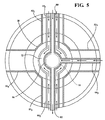
図2および図5を参照すると、複数の支柱アセンブリ48がタービン排気ケーシング25の周りで円形に離間配置されている。支柱アセンブリは、内側リング38を支持するために外側リング36から内側リング38へ向けて半径方向内側に延在する。ベアリングハウジング50は、内側リング38の半径方向内側の面に支持され、かつタービンロータ31を支持するための(参照符号51で図示される)後方ベアリングを封入するために設けられる。各支柱アセンブリ48は、外側リング36および内側リング38に固定される構造支柱52と、ガス経路42を通過する高温ガスから支柱52を隔離して保護するために支柱52を包囲するとともに外側流路壁44と内側流路壁46との間に延在するフェアリング54と、を含む(図3も参照されたい)。
With reference to FIGS. 2 and 5, a plurality of strut assemblies 48 are spaced apart in a circle around the turbine exhaust casing 25. The strut assembly extends radially inward from the
図3に図示されるように、各々の支柱52は、エンジンの軸方向に細長く延在し、軸方向に広がる外側側壁56,58を規定する。また支柱52は、半径方向および円周方向において内側リング38を位置決めするべく実質的な構造支持部を提供するためにおおむね堅固な構造部材として形成される。さらに各支柱52には、支柱52の中央部分を通って半径方向に広がる軸方向細長支柱キャビティ60が形成されており、軸方向細長支柱キャビティ60は、外側側壁56,58に平行に延在して向かい合う軸方向細長内側キャビティ壁56a,58aによって規定される。
As shown in FIG. 3, each
図2を参照すると、本発明の一態様によれば、支柱52は外側リング36および内側リング38に対して、例えば溶着しない取付けあるいは非一体的な取付けで取り外し可能に取付けられている。図示された実施形態では支柱52は、外側および内側リング36,38に当接されており、かつねじ付きボルトまたはスタッド接続部62などの取り外し可能な固定接続部によって外側および内側リング36,38に取り付けられている。
Referring to FIG. 2, according to one aspect of the present invention, the
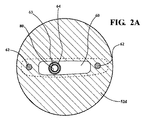
さらに図2および図2Aに図示されるように、支柱52には、円形頂部52dなどの細長頂部52dが形成されてもよい。頂部52dは、ケーシング25の外側リング36への固定を容易にするために設けられてもよい。ケーシングからの側壁荷重および/または後荷重が頂部52dに伝達されるがボルトまたはスタッド接続部62によって支持されないように、ケーシングと頂部52dとの間にはぴったりとした嵌合がもたらされる。図2Bには頂部52d’に関する代替構造が図示される。頂部52d’は長円形構造を有しており、図2Aの円形構造に関して述べた様式と同様の様式でケーシング25の側壁荷重および/または後荷重を受け取るよう設計されている。
Further, as shown in FIGS. 2 and 2A, the
代替的には支柱52は細長頂部を備えずに形成されてもよい。言い換えると支柱52は、直線的な壁を備えるよう、つまりケーシング25の外側リング36との接合部まで一定の断面で延在するよう形成されてもよい。この場合、ボルトまたはスタッド接続部62が、他の状況では上述の頂部52d,52d’に伝わる負荷を支持する。
Alternatively, the
本明細書(図5)には4つの支柱52が示されているが、本発明の範囲内で他の数の支柱52が設けられてもよいことを理解されたい。例えば8つの支柱52または他の数の支柱が設けられてもよい。
Although four
加えて4つのボルトまたはスタッド62が図2に図示されている、つまり支柱52の半径方向外側位置および半径方向内側位置のそれぞれに2つずつ配置されている。一方で2つのみのボルトまたはスタッドが設けられてもよい。このとき、ボルトまたはスタッドの各々は、支柱52の半径方向外側端部および半径方向内側端部のそれぞれでの外側リング36および内側リング38への取り付けのために、支柱52の長さ全体にわたって半径方向に延在する。
In addition, four bolts or
図2および図3を参照すると、本発明の態様によれば、二次空気システム(SAS)が設けられる。SASは、支柱キャビティ60を通るよう規定される第1のパージ空気経路63を含み、かつ外側リングにおける空気進入位置66から、内側リング36に取り付けられかつベアリングハウジング50を包囲するシール壁70における半径方向内側位置68へ延在する筒状抽気経路部材64によって規定されてもよい。第1の内側リングチャンバ72は、内側リング38から半径方向内側に配置されており、かつシール壁70とベアリングハウジング50との間に規定される。参照符号74で図示される第1の冷却空気供給ラインは、空気経路部材64に冷却空気を提供する。例えば空気経路部材64への冷却空気は、高圧コンプレッサ12の所定のステージから、例えばコンプレッサ12の8番目のステージの抽気を提供されてもよい(図1も参照されたい)。第1の冷却空気供給ライン74を経て提供された空気は、空気経路部材64内に流入する前に例えば熱交換器を通過して冷却されてもよい。以下の説明から明らかなように、空気経路部材64を経て提供された空気は、冷却空気作用と同様に、高温ガスの入口に対して、タービン排気ケーシング25内の特定の領域に圧力をかけるパージ空気作用を提供する。例えば以下で詳述するように、空気経路部材64は、支柱キャビティ60を介して第1の内側リングチャンバ72へ向けて冷却空気またはパージ空気を半径方向内側に誘導する。
With reference to FIGS. 2 and 3, according to aspects of the present invention, a secondary air system (SAS) is provided. The SAS includes a first
図2に図示されるように、第2の内側リングチャンバ76は、第1の内側リングチャンバ72から半径方向外側において、内側リング38とシール壁70との間に規定される。支柱キャビティ60は、内側リング38を通って延在するよう設けられる貫通路77を介して第2の内側リングチャンバ76と流体連通している。支柱キャビティ60は、冷却およびパージ空気を支柱52の半径方向内側端部52bから支柱52の半径方向外側端部52aへ向けて半径方向外側に誘導するために、SASの第2のパージ空気経路78を規定する。第2の内側リングチャンバ76は、より詳細に後述するように第1のパージ空気経路63からの空気および筒状ディスク冷却空気からの空気の混合体として、第2のパージ空気経路78のための冷却およびパージ空気を受け取る。
As illustrated in FIG. 2, the second
支柱の52の半径方向外側端部52aおよび半径方向内側端部52bは、タービン排気ケーシング25内に制御されたパージ空気流を提供するために本明細書で開示されるように、既定のパージ空気通路およびオリフィスを除いて、外側および内側リング36,38と基本的なシーリング係合部を形成することに留意されたい。
The radially
任意で、抽気経路部材64を通って延在するオイル供給ライン80が設けられてもよい。オイル供給ライン80は、ベアリング51にオイルを提供してもよく、かつ支柱アセンブリ48に伝達される熱から(つまりガス経路42内の高温ガス流から)パージ空気によって保護されている。この時、第1および第2のパージ空気経路63,78の両方を流れるパージ空気が、オイル供給ライン80への保護空気バリアを提供する。オイル供給ライン80および該ライン内のオイルは、エンジンが急停止した場合つまりオイルがライン80内を流れなくなった場合の「トリップ」または「負荷降下」状態中に特に生じる可能性のあるオイル供給ライン80内でのコーキング傾向を防止するか減少させる温度に維持される必要がある。第2のパージ空気経路78を通る空気の半径方向外側への流れは、支柱52と第1のパージ空気経路63そして関連付けられたオイル供給ライン80との間に熱バッファを提供する。さらに第1のパージ空気経路63を流れる冷却空気流は、増大された空気流量、つまり流速がより低いオイル供給ライン80への冷却流を提供するのに基本的に必要な空気流量よりも大きな空気流量を提供するようになされる。第1のパージ空気経路63を通るより低い流速は、流れに誘起される振動が発生する傾向が関連して低減されるように、抽気経路部材64を通ってより低いマッハ数を規定する。
Optionally, an
図5から明らかなように複数の支柱521,522,523,524が例示されている。支柱522には、ベアリング51からそしてタービン排気ケーシング25からオイルを運び出すために、ベアリングハウジング50から延在するオイルリターンライン82が設けられてもよい。加えて第1の内側リングチャンバ72へパージ空気を導入するために複数の抽気経路部材641,642,643が設けられてもよい。
As is clear from FIG. 5, a plurality of
図2を参照すると、第1のパージ空気経路63を通過する冷却空気またはパージ空気は第1の内側リングチャンバ72に流入し、この空気の一部は、低圧タービン20の最終ステージ84へ向けてチャンバ72内を軸方向上流へまたは前方方向へ流動する。第1のリングチャンバ72内で前方に流れる空気の一部は、ベアリングハウジング50におけるシール85に対してシール圧力を提供する。つまりチャンバ72内の空気圧は、オイルがシール85を通って流出することを防止するためにベアリングハウジング50とロータシャフト31との間の位置においてシール85の外側にシール圧力空気を提供する。前方に流れる空気の残りの部分は、第1の内側リングチャンバ72からロータ31に隣接するシール87を通って第2の内側リングチャンバ76へ向けて流動する。
Referring to FIG. 2, cooling air or purge air that passes through the first
加えて第1のパージ空気経路63からの空気の一部は、オリフィス89へ向けて第1の内側リングチャンバ72内を軸方向下流つまり後方に流動して、後方シールにおけるベアリングコンパートメントの後方部分にパージ/冷却空気を提供し、出力タービン前方キャビティ73からベアリングコンパートメントを含むベアリングキャビティ53への空気および熱の侵入を防ぐ。
In addition, a portion of the air from the first
タービン20の最終ステージ84は、高圧コンプレッサ12から導管91(図1)などを介して抽出冷却空気を受け取ってもよい。少なくともこの空気の一部はディスク冷却キャビティ90に提供される。例えば冷却空気流93は、高圧コンプレッサ12の9番目のステージから提供されてもよく、かつタービン20の最終ステージ84内の構成要素およびその付近の構成要素を冷却するためにかつタービン排気ケーシング25への制御された流れまたは調整された流れを提供するために分配されてもよい。特にロータシャフト31におけるオリフィス86は、最終タービンステージ84のディスク冷却キャビティ90から第2の内側リングチャンバ76への冷却空気の制御された抽出流88を提供する。ここで抽出流88は、参照符号92で概略的に図示される位置で第1のパージ空気経路63によって提供される空気と混ざり合い、混合流94を形成する。混合流94の一部96は、シール98を経て第2の内側リングチャンバ76から流出し、最終タービンステージ84と内側流路壁46との間の接合部におけるシール102を高温排気ガスが通過することを防止するために内側流路壁チャンバ100にパージ空気を提供する。
The final stage 84 of the
混合流94のさらなる部分は、第2の内側リングチャンバ76を通り、通路77を経て第2のパージ空気経路78へ向けて軸方向前方に流動する。つまり混合流は支柱52の開放キャビティ60内に流入し、そして支柱52の半径方向外側端部52aへ向けて外側に流動する。図3を参照すると、支柱52の半径方向外側端部52aには、複数の低損失パージ流オリフィス104が形成されている。オリフィス104は、内側キャビティ壁56a,58aから外側側壁56,58のそれぞれへ向けて支柱52の側板を横方向に貫通して延在する。パージ流オリフィス104は、第2のパージ空気経路78のための流出通路を規定し、混合流94が、開放キャビティ60から、支柱52の外面108と支柱52を包囲するシールド110との間で支柱保護ギャップ106として規定される支柱52の外側の領域に流出できるようにする。シールド110が、外側リング36と内側リング38との間で半径方向に広がっており、かつ外側リング36と内側リング38とに取り付けられていてもよい。
A further portion of the mixed stream 94 flows axially forward through the second
図2に図示されるように、混合空気94のうちオリフィス104を通過する部分は、シールド110の外側縁部を通って支柱保護ギャップ106から流出し得る半径方向外側部分を含む。言い換えると、(半径方向外側前方ギャップ112aおよび半径方向外側後方ギャップ112bによって図示される)損失が小さいつまり低損失なギャップが、シールド110と外側リング36との間に設けられてもよい。既定のまたは制御された量のパージ空気が、前方ギャップ112aおよび後方ギャップ112bから外側ケーシングキャビティ40aに流動してもよい。パージ空気のうち前方に流れる部分114aは、後方タービンシール116に隣接する、つまり最終ステージタービンリングセグメント118の下流端部における、外側ケーシングキャビティ40内の空気圧を増大させる。パージ空気の一部114aと最終ステージのタービンケーシングキャビティ120における冷却/パージ空気の給気119とは、ガス経路42からの高温ガスが外部に流出することを防ぐための陽圧パージ空気を提供する。最終ステージタービンケーシングキャビティ120に供給されるパージ/冷却空気は、高圧コンプレッサ12のさらなるステージから、例えばコンプレッサ12の12番目のステージから、提供されてもよいことに留意されたい。
As illustrated in FIG. 2, the portion of the mixed air 94 that passes through the
パージ空気のうち後方に流れる部分114bは、出力タービン22を用いて前方外側シール122に隣接する外側ケーシングキャビティ40a内の空気圧を増大させる。パージ空気の一部114bは、出力タービン22への入口におけるガス経路42から高温ガスが外部に流出することを防止するために陽圧パージ空気を提供する。後方に流れる部分114bはさらに、支柱シールド106およびフェアリング54との間で半径方向内側へ向けて流動し(流れ123で図示される)、出力タービン22とともに前方内側シール124に隣接する内側ケーシングキャビティ40b内の圧力を高め、内側ケーシングキャビティ40b内への高温ガスの流出を防止するための陽圧を提供する。
The portion 114b of the purge air that flows backward increases the air pressure in the outer casing cavity 40a adjacent to the front
図2を参照すると、混合気94のうちオリフィス104から支柱保護ギャップ106(図3)に流入するさらなる部分は、オリフィス104と内側リング38との間に広がる支柱保護ギャップ106の半径方向部分に沿って、支柱保護ギャップ106によっておおむね規定される空気経路128に沿って半径方向に移動する半径方向内側部分126を含む。混合気94の半径方向内側部分126は、図3にも図示されるようにシールド110と内側リング38との間に規定される損失が小さいつまり低損失な半径方向内側ギャップにおける支柱保護ギャップ106から流出する。混合気94のうち半径方向内側部分126によって規定される流れは、支柱52周りに冷却空気バリアを形成し、かつ混合気94のうち半径方向内側ギャップ130を通過する流れは、内側ケーシングキャビティ40bに付加的なパージ空気131を提供する1つ以上の半径方向内側ギャップ130を通過する流れはさらに、内側ケーシングキャビティ40b内の構成要素およびその付近の構成要素を冷却する。本発明の好ましい構造では、支柱保護ギャップ106に流入する混合気94のうち少なくとも10%(つまり10%以上)が、混合空気の流れの半径方向内側部分126を形成してギャップ130から流出すべきである。支柱保護ギャップ106に供給される混合空気の流れの特定の形態において、混合空気の流れ94の約3分の2が、前方に流れる部分114aおよび後方に流れる部分114bを形成するために半径方向外側ギャップ112a,112bを通過するよう供給されてもよく、かつ混合空気の流れの約3分の1は、支柱ギャップ106を通って半径方向内側ギャップ130へ向けて半径方向内側に流動するよう供給されてもよい。
Referring to FIG. 2, the further portion of the air-fuel mixture 94 that flows from the
さらに図2、図3および図4に図示されるように、混合気94の一部は、内側リング38に隣接する支柱52の半径方向内側端部52bにおいて開放キャビティ60から軸方向下流に延在するオリフィス132を通って開放キャビティ60から直接分配される。オリフィス132は、内側リング38または支柱52に形成されてよいことを理解されたい。オリフィス132を通過する混合気94の流れは、内側ケーシングキャビティ40bにさらなるパージ空気流134(図2および図3)を供給する。パージ空気流134は、出力タービン22の前方内側シール124における陽圧を維持するためにかつタービン排気ケーシング構成要素を冷却するために半径方向内側ギャップ130を通過するパージ空気流131と混ざり合ってもよい。
As further illustrated in FIGS. 2, 3, and 4, a portion of the air-fuel mixture 94 extends axially downstream from the
構成要素を冷却する上述の二次空気システムは、構成要素を形成する金属の温度限界内にタービン排気ケーシング構成要素の温度を維持するためにかつタービンケーシング構成要素同士の間の温度バランスを維持するために、数個の熱交換機構を提供する。本発明の一態様によれば、上述のSASは、例えばエンジン10のベースライン運転中に必要になる可能性のある、ガス経路42からの高温ガスの漏出を防止する陽圧を形成するパージ空気を提供する。特にパージ空気は、タービン排気ケーシング25内の外側および内側流路壁44,46に関連付けられたシールにおける高温ガスの漏出を防止したり制限したりする。
The secondary air system described above for cooling the components maintains the temperature balance between the turbine casing components and to maintain the temperature of the turbine exhaust casing components within the temperature limits of the metal forming the components. For this purpose, several heat exchange mechanisms are provided. According to one aspect of the invention, the SAS described above is purge air that creates a positive pressure that prevents leakage of hot gas from the gas path 42 that may be required, for example, during baseline operation of the
他の態様によれば、SASシステムは、タービン排気ケーシング25と熱交換する構成要素を冷却するために提供される。特に支柱52の内面および外面には冷却空気流が供給される。つまり冷却空気流は、開放キャビティの表面に沿ってかつ外面108に沿って流れる。さらにシールド110の半径方向外側縁部および半径方向内側縁部におけるギャップ112a,112bおよび130から流出する混合気94は、タービン排気ケーシングキャビティ40内に冷却および熱吸収能力をもたらす。このとき混合気94が自由対流によってケーシングキャビティ40の領域を形成する表面を冷却する。例えばキャビティ40内の混合気94は、半径方向に延在する接続パージ空気経路に沿ってシールド106とフェアリング54との間を対流によって流動してもよい。半径方向に延在する接続パージ空気経路は、フェアリング54を冷却してタービン排気ケーシングキャビティ内にパージ空気を分配できるようにするために、外側キャビティ部40aと内側キャビティ部40bとを接続する。
According to another aspect, a SAS system is provided for cooling components that exchange heat with the turbine exhaust casing 25. In particular, a cooling air flow is supplied to the inner and outer surfaces of the
さらなる態様によれば、SASは、タービン排気ケーシングキャビティ40内の空気の温度を所定のレベル以下に維持するために熱吸収能力を提供する。なお、そうしない場合には、タービン排気ケーシング25内の構成要素を合金にすることに関して問題が生じることがある。特に本願のSASは、タービン排気ケーシング構成要素を、タービン排気ケーシングキャビティ40内に適切な冷却および熱吸収を提供することによって、よりコストの低い低温合金を用いて構成できるようにする。
According to a further aspect, the SAS provides heat absorption capability to maintain the temperature of the air in the turbine
本発明のSASは、エンジン動作の変動中の半径方向外側構成要素と半径方向内側構成要素との間の温度バランスの維持をさらに容易にする。具体的には、本明細書に開示される半径方向内側および半径方向外側の空気の流れは、状態変移中の構成要素間の温度バランスを維持するために。タービン排気ケーシング25内の温度分散をもたらす。 The SAS of the present invention further facilitates maintaining a temperature balance between the radially outer component and the radially inner component during variations in engine operation. Specifically, the radially inner and radially outer air flows disclosed herein are intended to maintain a temperature balance between components during state transitions. This provides temperature dispersion within the turbine exhaust casing 25.
加えてオイル供給ライン80に関連して説明したように、本発明のSASにおける複数の空気経路は、エンジンが急停止する際に生じる状態において熱バリアを提供する。オイル供給ライン80は、より高温となった構成要素からの「ヒートソーク」の影響を遅滞させるための熱吸収能力を提供する空気バリアによって形成される複数の層によって包囲されている。さらに第1および第2の内側リングチャンバ74,76によって形成される複数の空気チャンバは、ベアリングハウジング50内に配置されるベアリングおよびオイルへの「ヒートソーク」の影響を遅滞させるためにベアリングハウジング50の周囲に熱吸収能力を提供する。
In addition, as described in connection with the
本発明の特定の実施形態について示しかつ説明してきたが、当業者には本発明の趣旨および範囲から逸脱することなくさまざまな他の変更および置き換えが可能であることは明らかであろう。したがって本発明の範囲内のすべてのそうした変更および置き換えが本願の特許請求の範囲に記載の範囲に包含されるよう意図されている。 While particular embodiments of the present invention have been shown and described, it will be apparent to those skilled in the art that various other changes and substitutions can be made without departing from the spirit and scope of the invention. Accordingly, all such modifications and substitutions within the scope of the present invention are intended to be included within the scope of the appended claims.
10 ガスタービンエンジン
12 高圧コンプレッサ
14 低圧コンプレッサ
16 燃焼器
17 タービンセクション
18 高圧タービン
20 低圧タービン
21 中間ケーシング
22 出力タービン
24 発電機
25 タービン排気ケーシング
26 第1の回転シャフト
28 第2の回転シャフト
30 第3の回転シャフト
31 ロータシャフト
32 ベーン
34 ブレード
36 外側リング(外側ケーシング)
38 内側リング(内側ケーシング)
40 外側ケーシングキャビティ
42 排気ガス経路
44 外側流路壁
46 内側流路壁
48 支柱アセンブリ
49 コーン(円錐部分)
50 ベアリングハウジング
51 ベアリング
52 支柱
53 ベアリングキャビティ
54 フェアリング
56 内側キャビティ壁
58 外側側壁
60 開放キャビティ
63 第1のパージ空気経路
64 抽気経路部材
66 空気進入位置
68 半径方向内側位置
70 シール壁
72 第1の内側リングチャンバ
73 出力タービン前方キャビティ
76 第2の内側リングチャンバ
77 貫通路
78 第2のパージ空気経路
80 オイル供給ライン
82 オイルリターンライン
84 最終タービンステージ
85,87,98,102 シール
86,89,104 オリフィス
88 抽出流
90 ディスク冷却キャビティ
91 導管
93 冷却空気流
94 混合気
100 内側流路壁チャンバ
106 支柱保護ギャップ
108 外面
110 シールド
112 半径方向外側ギャップ
116 後方タービンシール
122 前方外側シール
124 前方内側シール
DESCRIPTION OF
38 Inner ring (inner casing)
40 Outer casing cavity 42 Exhaust gas path 44 Outer
DESCRIPTION OF SYMBOLS 50 Bearing housing 51
Claims (19)
前記タービンアセンブリは、外側ケーシングと、内側ケーシングと、外側流路壁と内側流路壁との間に規定される環状の排気ガス経路と、前記ガス経路から半径方向外側および半径方向内側に配置されるタービン排気ケーシングキャビティと、を有しており、さらに、
前記外側ケーシングに対して前記内側ケーシングを支持させる複数の構造支柱と;
前記外側流路壁と前記内側流路壁との間に広がる領域内で前記支柱の各々を包囲するフェアリングと;
前記内側ケーシングから半径方向内側の少なくとも1つの構成要素へ向けてパージ空気を供給するためにパージ冷却空気を前記内側ケーシングに導入する、前記支柱の少なくとも1つを通って半径方向内側に延在する第1のパージ空気経路と;
前記排気ケーシングキャビティのうち前記外側流路壁から半径方向外側の外側位置へ向けてパージ空気を流動させるよう、前記少なくとも1つの構成要素から半径方向外側に前記パージ冷却空気をさらに誘導するために、少なくとも1つの前記支柱を通って半径方向外側に延在する第2のパージ空気経路と;
を備えることを特徴とするタービンアセンブリ。 A turbine assembly in a turbine engine,
The turbine assembly is disposed on an outer casing, an inner casing, an annular exhaust gas passage defined between the outer passage wall and the inner passage wall, and radially outward and radially inward from the gas passage. A turbine exhaust casing cavity, and
A plurality of structural supports for supporting the inner casing with respect to the outer casing;
A fairing that surrounds each of the struts in a region extending between the outer channel wall and the inner channel wall;
Extending radially inward through at least one of the struts introducing purge cooling air into the inner casing to supply purge air from the inner casing toward at least one component radially inward. A first purge air path;
To further direct the purge cooling air radially outward from the at least one component to cause purge air to flow radially outward from the outer flow path wall of the exhaust casing cavity; A second purge air path extending radially outward through at least one of said struts;
A turbine assembly comprising:
前記タービンアセンブリは、外側ケーシングと、内側ケーシングと、外側流路壁と内側流路壁との間に規定される環状の排気ガス経路と、前記ガス経路から半径方向外側および半径方向内側に配置されたタービン排気ケーシングキャビティと、を有しており、さらに、
前記内側ケーシングと前記外側ケーシングとの間に延在する複数の支柱と;
前記内側ケーシングから半径方向内側の少なくとも1つの構成要素へ向けてパージ空気を供給するためにパージ空気を前記内側ケーシングへ誘導する、前記支柱の少なくとも1つを通って半径方向内側に延在する第1のパージ空気経路と;
前記内側ケーシングに配置される流入部を有するとともに、前記排気ケーシングキャビティのうち前記外側流路壁から半径方向外側の外側位置へ向けてパージ空気を流動させるためにパージ冷却空気を半径方向外側へさらに誘導するために少なくとも1つの前記支柱を通って半径方向外側に延在する第2のパージ空気経路と;
を備えることを特徴とするタービンアセンブリ。 A turbine assembly in a turbine engine,
The turbine assembly is disposed on an outer casing, an inner casing, an annular exhaust gas passage defined between the outer passage wall and the inner passage wall, and radially outward and radially inward from the gas passage. A turbine exhaust casing cavity, and
A plurality of struts extending between the inner casing and the outer casing;
Extending radially inward through at least one of the struts for directing purge air to the inner casing to supply purge air from the inner casing toward at least one component radially inward. One purge air path;
In addition to having an inflow portion disposed in the inner casing, purge cooling air is further radially outward to allow the purge air to flow from the outer flow path wall to a radially outer position of the exhaust casing cavity. A second purge air path extending radially outward through at least one said strut for guidance;
A turbine assembly comprising:
前記第2のパージ空気通路への流入部へ向けてパージ空気を軸方向後方に誘導するチャンバを含むことを特徴とする請求項14に記載のタービンアセンブリ。 A passage extending axially forward in the turbine engine for directing the purge air flowing out of the first purge air passage to a position adjacent to a turbine stage cooling cavity, wherein the purge air is in the turbine Mixed with air from the stage cooling cavity, and
The turbine assembly of claim 14, further comprising a chamber that guides purge air axially rearward toward an inlet to the second purge air passage.
前記タービンステージ冷却キャビティには、前記第1の供給位置とは異なる前記圧縮セクションの第2の供給位置から冷却空気が供給されることを特徴とする請求項15に記載のタービンアセンブリ。 The first purge air path is supplied with purge air from a first supply location in the compression section of the turbine engine, and
The turbine assembly according to claim 15, wherein cooling air is supplied to the turbine stage cooling cavity from a second supply position of the compression section different from the first supply position.
前記支柱からの前記パージ空気の流出のために、前記外側流路壁から半径方向外側の位置において前記側壁を通って規定される支柱オリフィスを含むことを特徴とする請求項14に記載のタービンアセンブリ。 The struts include axial sidewalls that extend in the axial direction, the opposing sidewalls defining a cavity that defines a second purge air path therebetween, and
The turbine assembly of claim 14, further comprising a strut orifice defined through the side wall at a location radially outward from the outer flow path wall for outflow of the purge air from the strut. .
Applications Claiming Priority (3)
| Application Number | Priority Date | Filing Date | Title |
|---|---|---|---|
| US13/746,486 US9316153B2 (en) | 2013-01-22 | 2013-01-22 | Purge and cooling air for an exhaust section of a gas turbine assembly |
| US13/746,486 | 2013-01-22 | ||
| PCT/US2014/012430 WO2014116626A2 (en) | 2013-01-22 | 2014-01-22 | Purge and cooling air for an exhaust section of a gas turbine assembly |
Publications (2)
| Publication Number | Publication Date |
|---|---|
| JP2016505108A true JP2016505108A (en) | 2016-02-18 |
| JP6189455B2 JP6189455B2 (en) | 2017-08-30 |
Family
ID=50031641
Family Applications (1)
| Application Number | Title | Priority Date | Filing Date |
|---|---|---|---|
| JP2015553907A Expired - Fee Related JP6189455B2 (en) | 2013-01-22 | 2014-01-22 | Purge and cooling air for the exhaust section of the gas turbine assembly |
Country Status (7)
| Country | Link |
|---|---|
| US (1) | US9316153B2 (en) |
| EP (1) | EP2948638B1 (en) |
| JP (1) | JP6189455B2 (en) |
| CN (1) | CN104919140B (en) |
| RU (1) | RU2638114C2 (en) |
| SA (1) | SA515360768B1 (en) |
| WO (1) | WO2014116626A2 (en) |
Cited By (2)
| Publication number | Priority date | Publication date | Assignee | Title |
|---|---|---|---|---|
| JP2018100666A (en) * | 2016-12-20 | 2018-06-28 | ドゥサン ヘヴィー インダストリーズ アンド コンストラクション カンパニー リミテッド | gas turbine |
| JP2022158583A (en) * | 2021-04-02 | 2022-10-17 | 三菱重工業株式会社 | gas turbine |
Families Citing this family (52)
| Publication number | Priority date | Publication date | Assignee | Title |
|---|---|---|---|---|
| EP2508713A1 (en) * | 2011-04-04 | 2012-10-10 | Siemens Aktiengesellschaft | Gas turbine comprising a heat shield and method of operation |
| US9850780B2 (en) * | 2012-12-29 | 2017-12-26 | United Technologies Corporation | Plate for directing flow and film cooling of components |
| JP6385955B2 (en) * | 2012-12-29 | 2018-09-05 | ユナイテッド テクノロジーズ コーポレイションUnited Technologies Corporation | Turbine frame assembly and method for designing a turbine frame assembly |
| US10240481B2 (en) * | 2012-12-29 | 2019-03-26 | United Technologies Corporation | Angled cut to direct radiative heat load |
| US9316153B2 (en) * | 2013-01-22 | 2016-04-19 | Siemens Energy, Inc. | Purge and cooling air for an exhaust section of a gas turbine assembly |
| US10329936B2 (en) * | 2013-08-07 | 2019-06-25 | United Technologies Corporation | Gas turbine engine aft seal plate geometry |
| FR3011035B1 (en) * | 2013-09-25 | 2015-10-09 | Snecma | EXHAUST CASE COMPRISING A FLUID EVACUATION DEVICE, AND TURBOMACHINE |
| US9598981B2 (en) * | 2013-11-22 | 2017-03-21 | Siemens Energy, Inc. | Industrial gas turbine exhaust system diffuser inlet lip |
| EP2930314B1 (en) * | 2014-04-08 | 2022-06-08 | Rolls-Royce Corporation | Generator with controlled air cooling amplifier |
| US10450881B2 (en) * | 2014-05-08 | 2019-10-22 | Siemens Aktiengesellschaft | Turbine assembly and corresponding method of operation |
| EP3155233B1 (en) * | 2014-06-10 | 2019-01-02 | Siemens Energy, Inc. | Gas turbine engine with rotor centering cooling system in an exhaust diffuser |
| US9822669B2 (en) | 2014-07-18 | 2017-11-21 | Siemens Energy, Inc. | Turbine assembly with detachable struts |
| US10443498B2 (en) * | 2014-08-15 | 2019-10-15 | United Technologies Corporation | Gas turbine engine cooling fluid metering system |
| US9803502B2 (en) * | 2015-02-09 | 2017-10-31 | United Technologies Corporation | Cooling passages for a mid-turbine frame |
| US10107200B2 (en) * | 2015-04-30 | 2018-10-23 | General Electric Company | Turbine engine thermal management |
| CN104819016B (en) * | 2015-05-05 | 2016-09-21 | 中国航空动力机械研究所 | Turbine rear trunnion bearing, cooling means and turbofan |
| GB201507818D0 (en) | 2015-05-07 | 2015-06-17 | Rolls Royce Plc | A gas turbine engine |
| FR3036442B1 (en) * | 2015-05-21 | 2021-07-16 | Snecma | TURBOMACHINE WITH A VENTILATION SYSTEM |
| WO2017015747A1 (en) * | 2015-07-24 | 2017-02-02 | Pratt & Whitney Canada Corp. | Multiple spoke cooling system and method |
| US10914193B2 (en) * | 2015-07-24 | 2021-02-09 | Pratt & Whitney Canada Corp. | Multiple spoke cooling system and method |
| US10443449B2 (en) | 2015-07-24 | 2019-10-15 | Pratt & Whitney Canada Corp. | Spoke mounting arrangement |
| US10247035B2 (en) | 2015-07-24 | 2019-04-02 | Pratt & Whitney Canada Corp. | Spoke locking architecture |
| US10975721B2 (en) | 2016-01-12 | 2021-04-13 | Pratt & Whitney Canada Corp. | Cooled containment case using internal plenum |
| US10577973B2 (en) | 2016-02-18 | 2020-03-03 | General Electric Company | Service tube for a turbine engine |
| US11041438B2 (en) * | 2016-04-06 | 2021-06-22 | General Electric Company | Gas turbine engine service tube mount |
| GB201613926D0 (en) * | 2016-08-15 | 2016-09-28 | Rolls Royce Plc | Inter-stage cooling for a turbomachine |
| FR3055355B1 (en) * | 2016-08-30 | 2020-06-19 | Safran Aircraft Engines | DEVICE AND METHOD FOR ADJUSTING GAMES BETWEEN A ROTOR AND A CONCENTRIC STATOR OF A TURBOMACHINE |
| DE102016217320A1 (en) * | 2016-09-12 | 2018-03-15 | Siemens Aktiengesellschaft | Gas turbine with separate cooling for turbine and exhaust housing |
| US20180080476A1 (en) * | 2016-09-19 | 2018-03-22 | United Technologies Corporation | Geared turbofan front center body thermal management |
| US20180149085A1 (en) * | 2016-11-28 | 2018-05-31 | General Electric Company | Exhaust frame cooling via cooling flow reversal |
| US10914185B2 (en) * | 2016-12-02 | 2021-02-09 | General Electric Company | Additive manufactured case with internal passages for active clearance control |
| US10450957B2 (en) * | 2017-01-23 | 2019-10-22 | United Technologies Corporation | Gas turbine engine with heat pipe system |
| US10808576B2 (en) | 2017-02-06 | 2020-10-20 | General Electric Company | Methods of replacing seals in exhaust frames of turbine systems and related components |
| JP6862292B2 (en) * | 2017-06-19 | 2021-04-21 | 川崎重工業株式会社 | Gas turbine engine |
| CN107559091A (en) * | 2017-08-28 | 2018-01-09 | 陈佳伟 | A kind of gas turbine |
| GB2566498B (en) * | 2017-09-15 | 2021-02-17 | Gkn Aerospace Sweden Ab | Turbine exhaust case cooling |
| US20190112946A1 (en) * | 2017-10-13 | 2019-04-18 | United Technologies Corporation | Double wall service tube with annular airflow passage |
| US10815830B2 (en) | 2017-12-21 | 2020-10-27 | Raytheon Technologies Corporation | Lightweight tierod |
| US20190345833A1 (en) * | 2018-05-11 | 2019-11-14 | United Technologies Corporation | Vane including internal radiant heat shield |
| RU2691203C1 (en) * | 2018-07-05 | 2019-06-11 | Публичное акционерное общество "ОДК-Уфимское моторостроительное производственное объединение" (ПАО "ОДК-УМПО") | Nozzle assembly of low-pressure turbine (lpt) of gas turbine engine (gte) (versions) and blade of lpt nozzle assembly (versions) |
| US11391179B2 (en) | 2019-02-12 | 2022-07-19 | Pratt & Whitney Canada Corp. | Gas turbine engine with bearing support structure |
| US11346249B2 (en) | 2019-03-05 | 2022-05-31 | Pratt & Whitney Canada Corp. | Gas turbine engine with feed pipe for bearing housing |
| US11428104B2 (en) | 2019-07-29 | 2022-08-30 | Pratt & Whitney Canada Corp. | Partition arrangement for gas turbine engine and method |
| JP7419002B2 (en) * | 2019-09-12 | 2024-01-22 | 三菱重工業株式会社 | Strut cover, exhaust casing and gas turbine |
| US11085313B2 (en) * | 2019-11-22 | 2021-08-10 | Raytheon Technologies Corporation | System and method for transporting lubricant through a vane |
| US11408297B2 (en) | 2020-01-27 | 2022-08-09 | Raytheon Technologies Corporation | Air seal assembly |
| US11047306B1 (en) | 2020-02-25 | 2021-06-29 | General Electric Company | Gas turbine engine reverse bleed for coking abatement |
| RU2757245C1 (en) * | 2020-07-23 | 2021-10-12 | Публичное акционерное общество "ОДК-Уфимское моторостроительное производственное объединение" (ПАО "ОДК-УМПО") | Nozzle apparatus of a high-pressure turbine of a gas turbine engine |
| GB202018430D0 (en) * | 2020-11-24 | 2021-01-06 | Rolls Royce Plc | Support assembly for gas turbine engine |
| CN112377267B (en) * | 2020-11-30 | 2024-02-20 | 中国电子科技集团公司第十六研究所 | Self-cooling high-speed ram air turbine generator |
| CN114183209B (en) * | 2021-11-25 | 2024-04-12 | 中盐华能储能科技有限公司 | Cold purging method for air turbine air inlet pipeline |
| US20240026820A1 (en) * | 2022-07-22 | 2024-01-25 | General Electric Company | Sump arrangement for a gas turbine engine |
Citations (5)
| Publication number | Priority date | Publication date | Assignee | Title |
|---|---|---|---|---|
| JP2005344680A (en) * | 2004-06-07 | 2005-12-15 | Hitachi Ltd | Two-axle type gas turbine |
| JP2006342802A (en) * | 2005-06-06 | 2006-12-21 | General Electric Co <Ge> | Counter-rotating turbofan engine |
| JP2009167800A (en) * | 2008-01-10 | 2009-07-30 | Mitsubishi Heavy Ind Ltd | Exhaust section structure of gas turbine and gas turbine |
| US20110079019A1 (en) * | 2009-10-01 | 2011-04-07 | Pratt & Whitney Canada Corp. | Cooling air system for mid turbine frame |
| US20120227371A1 (en) * | 2011-03-09 | 2012-09-13 | General Electric Company | System for cooling and purging exhaust section of gas turbine engine |
Family Cites Families (29)
| Publication number | Priority date | Publication date | Assignee | Title |
|---|---|---|---|---|
| JPS58206803A (en) * | 1982-05-27 | 1983-12-02 | Hitachi Ltd | Nozzle segment of gas turbine |
| US4561246A (en) | 1983-12-23 | 1985-12-31 | United Technologies Corporation | Bearing compartment for a gas turbine engine |
| US4920742A (en) | 1988-05-31 | 1990-05-01 | General Electric Company | Heat shield for gas turbine engine frame |
| US4987736A (en) | 1988-12-14 | 1991-01-29 | General Electric Company | Lightweight gas turbine engine frame with free-floating heat shield |
| US4989406A (en) | 1988-12-29 | 1991-02-05 | General Electric Company | Turbine engine assembly with aft mounted outlet guide vanes |
| JP3142850B2 (en) | 1989-03-13 | 2001-03-07 | 株式会社東芝 | Turbine cooling blades and combined power plants |
| US4979872A (en) | 1989-06-22 | 1990-12-25 | United Technologies Corporation | Bearing compartment support |
| FR2685381B1 (en) | 1991-12-18 | 1994-02-11 | Snecma | TURBINE HOUSING BOUNDING AN ANNULAR GAS FLOW VEIN DIVIDED BY RADIAL ARMS. |
| US5292227A (en) | 1992-12-10 | 1994-03-08 | General Electric Company | Turbine frame |
| US5609467A (en) | 1995-09-28 | 1997-03-11 | Cooper Cameron Corporation | Floating interturbine duct assembly for high temperature power turbine |
| JP4375883B2 (en) | 2000-06-02 | 2009-12-02 | 本田技研工業株式会社 | Seal air supply system for gas turbine engine bearings |
| RU2196896C1 (en) * | 2001-09-13 | 2003-01-20 | Открытое акционерное общество "А.Люлька-Сатурн" | Cooled turbine of gas turbine engine |
| ITMI20012584A1 (en) * | 2001-12-10 | 2003-06-10 | Nuovo Pignone Spa | SEPARATION STRUCTURE OF HIGH AND LOW TURBO EXPANSION OF A GAS TURBINE |
| ITMI20021465A1 (en) | 2002-07-03 | 2004-01-05 | Nuovo Pignone Spa | EASY ASSEMBLY THERMAL SHIELDING DEVICE FOR A COUPLING BETWEEN A COOLING PIPE AND A REA THROUGH DRILLING |
| US7383686B2 (en) | 2004-12-13 | 2008-06-10 | Honeywell International Inc. | Secondary flow, high pressure turbine module cooling air system for recuperated gas turbine engines |
| RU2287073C2 (en) * | 2004-12-14 | 2006-11-10 | Открытое акционерное общество "Авиадвигатель" | Power turbine of gas-turbine engine |
| US20070151257A1 (en) | 2006-01-05 | 2007-07-05 | Maier Mark S | Method and apparatus for enabling engine turn down |
| US20100303608A1 (en) * | 2006-09-28 | 2010-12-02 | Mitsubishi Heavy Industries, Ltd. | Two-shaft gas turbine |
| US7926289B2 (en) | 2006-11-10 | 2011-04-19 | General Electric Company | Dual interstage cooled engine |
| US8312726B2 (en) | 2007-12-21 | 2012-11-20 | United Technologies Corp. | Gas turbine engine systems involving I-beam struts |
| JP4969500B2 (en) | 2008-03-28 | 2012-07-04 | 三菱重工業株式会社 | gas turbine |
| US8251652B2 (en) * | 2008-09-18 | 2012-08-28 | Siemens Energy, Inc. | Gas turbine vane platform element |
| US8500392B2 (en) * | 2009-10-01 | 2013-08-06 | Pratt & Whitney Canada Corp. | Sealing for vane segments |
| FR2954401B1 (en) | 2009-12-23 | 2012-03-23 | Turbomeca | METHOD FOR COOLING TURBINE STATORS AND COOLING SYSTEM FOR ITS IMPLEMENTATION |
| US9279341B2 (en) * | 2011-09-22 | 2016-03-08 | Pratt & Whitney Canada Corp. | Air system architecture for a mid-turbine frame module |
| US8863531B2 (en) * | 2012-07-02 | 2014-10-21 | United Technologies Corporation | Cooling apparatus for a mid-turbine frame |
| WO2014105515A1 (en) * | 2012-12-29 | 2014-07-03 | United Technologies Corporation | Cooling architecture for turbine exhaust case |
| WO2014105616A1 (en) * | 2012-12-29 | 2014-07-03 | United Technologies Corporation | Turbine exhaust case architecture |
| US9316153B2 (en) * | 2013-01-22 | 2016-04-19 | Siemens Energy, Inc. | Purge and cooling air for an exhaust section of a gas turbine assembly |
-
2013
- 2013-01-22 US US13/746,486 patent/US9316153B2/en active Active
-
2014
- 2014-01-22 EP EP14702423.6A patent/EP2948638B1/en active Active
- 2014-01-22 CN CN201480004930.2A patent/CN104919140B/en not_active Expired - Fee Related
- 2014-01-22 WO PCT/US2014/012430 patent/WO2014116626A2/en active Application Filing
- 2014-01-22 RU RU2015130230A patent/RU2638114C2/en active
- 2014-01-22 JP JP2015553907A patent/JP6189455B2/en not_active Expired - Fee Related
-
2015
- 2015-07-21 SA SA515360768A patent/SA515360768B1/en unknown
Patent Citations (5)
| Publication number | Priority date | Publication date | Assignee | Title |
|---|---|---|---|---|
| JP2005344680A (en) * | 2004-06-07 | 2005-12-15 | Hitachi Ltd | Two-axle type gas turbine |
| JP2006342802A (en) * | 2005-06-06 | 2006-12-21 | General Electric Co <Ge> | Counter-rotating turbofan engine |
| JP2009167800A (en) * | 2008-01-10 | 2009-07-30 | Mitsubishi Heavy Ind Ltd | Exhaust section structure of gas turbine and gas turbine |
| US20110079019A1 (en) * | 2009-10-01 | 2011-04-07 | Pratt & Whitney Canada Corp. | Cooling air system for mid turbine frame |
| US20120227371A1 (en) * | 2011-03-09 | 2012-09-13 | General Electric Company | System for cooling and purging exhaust section of gas turbine engine |
Cited By (4)
| Publication number | Priority date | Publication date | Assignee | Title |
|---|---|---|---|---|
| JP2018100666A (en) * | 2016-12-20 | 2018-06-28 | ドゥサン ヘヴィー インダストリーズ アンド コンストラクション カンパニー リミテッド | gas turbine |
| US10502078B2 (en) | 2016-12-20 | 2019-12-10 | Doosan Heavy Industries Construction Co., Ltd. | Gas turbine |
| JP2022158583A (en) * | 2021-04-02 | 2022-10-17 | 三菱重工業株式会社 | gas turbine |
| JP7352590B2 (en) | 2021-04-02 | 2023-09-28 | 三菱重工業株式会社 | gas turbine |
Also Published As
| Publication number | Publication date |
|---|---|
| WO2014116626A3 (en) | 2014-09-18 |
| RU2638114C2 (en) | 2017-12-11 |
| US9316153B2 (en) | 2016-04-19 |
| CN104919140A (en) | 2015-09-16 |
| EP2948638A2 (en) | 2015-12-02 |
| WO2014116626A2 (en) | 2014-07-31 |
| US20140205447A1 (en) | 2014-07-24 |
| RU2015130230A (en) | 2017-03-03 |
| CN104919140B (en) | 2018-03-27 |
| EP2948638B1 (en) | 2020-10-28 |
| JP6189455B2 (en) | 2017-08-30 |
| SA515360768B1 (en) | 2018-09-24 |
Similar Documents
| Publication | Publication Date | Title |
|---|---|---|
| JP6189455B2 (en) | Purge and cooling air for the exhaust section of the gas turbine assembly | |
| EP3214373B1 (en) | Bundled tube fuel nozzle with internal cooling | |
| JP6176723B2 (en) | Combustor cap assembly | |
| US9677412B2 (en) | Shroud arrangement for a gas turbine engine | |
| US10240532B2 (en) | Frame junction cooling holes | |
| US9611754B2 (en) | Shroud arrangement for a gas turbine engine | |
| RU2610373C2 (en) | System and method of recycling of hot gas flowing through gas turbine and gas turbine | |
| US8616832B2 (en) | Turbine assemblies with impingement cooling | |
| JP6602094B2 (en) | Combustor cap assembly | |
| US9920647B2 (en) | Dual source cooling air shroud arrangement for a gas turbine engine | |
| US11029028B2 (en) | Gas turbine annular combustor arrangement | |
| US20170138267A1 (en) | Bundled Tube Fuel Nozzle Assembly With Liquid Fuel Capability | |
| JP2014181701A (en) | Flow sleeve assembly for combustion module of gas turbine combustor | |
| US10670272B2 (en) | Fuel injector guide(s) for a turbine engine combustor | |
| US20140341721A1 (en) | Shroud arrangement for a gas turbine engine | |
| US20140000267A1 (en) | Transition duct for a gas turbine | |
| EP3392566A1 (en) | Combustor panel cooling arrangements | |
| US9995172B2 (en) | Turbine nozzle with cooling channel coolant discharge plenum | |
| US10378773B2 (en) | Turbine engine diffuser assembly with airflow mixer | |
| US20150159873A1 (en) | Compressor discharge casing assembly | |
| JP6016655B2 (en) | Gas turbine tail tube seal and gas turbine | |
| US9745894B2 (en) | Compressor air provided to combustion chamber plenum and turbine guide vane | |
| CN107849938A (en) | More spoke cooling systems and method |
Legal Events
| Date | Code | Title | Description |
|---|---|---|---|
| A131 | Notification of reasons for refusal |
Free format text: JAPANESE INTERMEDIATE CODE: A131 Effective date: 20160715 |
|
| A977 | Report on retrieval |
Free format text: JAPANESE INTERMEDIATE CODE: A971007 Effective date: 20160714 |
|
| A601 | Written request for extension of time |
Free format text: JAPANESE INTERMEDIATE CODE: A601 Effective date: 20161017 |
|
| A601 | Written request for extension of time |
Free format text: JAPANESE INTERMEDIATE CODE: A601 Effective date: 20161215 |
|
| A521 | Request for written amendment filed |
Free format text: JAPANESE INTERMEDIATE CODE: A523 Effective date: 20170113 |
|
| TRDD | Decision of grant or rejection written | ||
| A01 | Written decision to grant a patent or to grant a registration (utility model) |
Free format text: JAPANESE INTERMEDIATE CODE: A01 Effective date: 20170703 |
|
| A61 | First payment of annual fees (during grant procedure) |
Free format text: JAPANESE INTERMEDIATE CODE: A61 Effective date: 20170802 |
|
| R150 | Certificate of patent or registration of utility model |
Ref document number: 6189455 Country of ref document: JP Free format text: JAPANESE INTERMEDIATE CODE: R150 |
|
| R250 | Receipt of annual fees |
Free format text: JAPANESE INTERMEDIATE CODE: R250 |
|
| R250 | Receipt of annual fees |
Free format text: JAPANESE INTERMEDIATE CODE: R250 |
|
| LAPS | Cancellation because of no payment of annual fees |