JP2016504502A - Metal cord with a highly permeable layer - Google Patents
Metal cord with a highly permeable layer Download PDFInfo
- Publication number
- JP2016504502A JP2016504502A JP2015547049A JP2015547049A JP2016504502A JP 2016504502 A JP2016504502 A JP 2016504502A JP 2015547049 A JP2015547049 A JP 2015547049A JP 2015547049 A JP2015547049 A JP 2015547049A JP 2016504502 A JP2016504502 A JP 2016504502A
- Authority
- JP
- Japan
- Prior art keywords
- cord
- threads
- layer
- thread
- rubber
- Prior art date
- Legal status (The legal status is an assumption and is not a legal conclusion. Google has not performed a legal analysis and makes no representation as to the accuracy of the status listed.)
- Pending
Links
- 229910052751 metal Inorganic materials 0.000 title claims abstract description 27
- 239000002184 metal Substances 0.000 title claims abstract description 27
- 229910052698 phosphorus Inorganic materials 0.000 claims abstract description 7
- 238000004804 winding Methods 0.000 claims description 26
- 229910052757 nitrogen Inorganic materials 0.000 claims description 6
- 229920001971 elastomer Polymers 0.000 description 66
- 239000005060 rubber Substances 0.000 description 63
- 230000002787 reinforcement Effects 0.000 description 47
- 239000011295 pitch Substances 0.000 description 31
- 229910000831 Steel Inorganic materials 0.000 description 18
- 239000010959 steel Substances 0.000 description 18
- 230000007797 corrosion Effects 0.000 description 15
- 238000005260 corrosion Methods 0.000 description 15
- 239000011324 bead Substances 0.000 description 14
- 238000012360 testing method Methods 0.000 description 13
- 239000003518 caustics Substances 0.000 description 12
- 238000004519 manufacturing process Methods 0.000 description 12
- 230000035699 permeability Effects 0.000 description 12
- 229910000975 Carbon steel Inorganic materials 0.000 description 9
- 238000010276 construction Methods 0.000 description 9
- 230000003014 reinforcing effect Effects 0.000 description 9
- 239000010962 carbon steel Substances 0.000 description 8
- 239000011248 coating agent Substances 0.000 description 8
- 238000000576 coating method Methods 0.000 description 8
- 238000005259 measurement Methods 0.000 description 8
- 239000000203 mixture Substances 0.000 description 8
- 230000035515 penetration Effects 0.000 description 8
- 238000000034 method Methods 0.000 description 7
- 230000001681 protective effect Effects 0.000 description 7
- 229910001369 Brass Inorganic materials 0.000 description 6
- 241000196324 Embryophyta Species 0.000 description 6
- 239000010951 brass Substances 0.000 description 6
- 229910052799 carbon Inorganic materials 0.000 description 6
- 239000004744 fabric Substances 0.000 description 6
- 239000010935 stainless steel Substances 0.000 description 6
- 229910001220 stainless steel Inorganic materials 0.000 description 6
- OKTJSMMVPCPJKN-UHFFFAOYSA-N Carbon Chemical compound [C] OKTJSMMVPCPJKN-UHFFFAOYSA-N 0.000 description 5
- 230000006835 compression Effects 0.000 description 5
- 238000007906 compression Methods 0.000 description 5
- XEEYBQQBJWHFJM-UHFFFAOYSA-N Iron Chemical compound [Fe] XEEYBQQBJWHFJM-UHFFFAOYSA-N 0.000 description 4
- 239000000853 adhesive Substances 0.000 description 4
- 230000001070 adhesive effect Effects 0.000 description 4
- 238000003490 calendering Methods 0.000 description 4
- 229910052804 chromium Inorganic materials 0.000 description 4
- 239000011651 chromium Substances 0.000 description 4
- 239000000463 material Substances 0.000 description 4
- 239000011159 matrix material Substances 0.000 description 4
- 229910052717 sulfur Inorganic materials 0.000 description 4
- 229910052725 zinc Inorganic materials 0.000 description 4
- 239000011701 zinc Substances 0.000 description 4
- 241001589086 Bellapiscis medius Species 0.000 description 3
- HCHKCACWOHOZIP-UHFFFAOYSA-N Zinc Chemical compound [Zn] HCHKCACWOHOZIP-UHFFFAOYSA-N 0.000 description 3
- 230000009471 action Effects 0.000 description 3
- 229910045601 alloy Inorganic materials 0.000 description 3
- 239000000956 alloy Substances 0.000 description 3
- 239000006229 carbon black Substances 0.000 description 3
- 230000015556 catabolic process Effects 0.000 description 3
- 239000002131 composite material Substances 0.000 description 3
- 238000006731 degradation reaction Methods 0.000 description 3
- 239000000806 elastomer Substances 0.000 description 3
- 229910052759 nickel Inorganic materials 0.000 description 3
- 230000035882 stress Effects 0.000 description 3
- XLYOFNOQVPJJNP-UHFFFAOYSA-N water Substances O XLYOFNOQVPJJNP-UHFFFAOYSA-N 0.000 description 3
- VYZAMTAEIAYCRO-UHFFFAOYSA-N Chromium Chemical compound [Cr] VYZAMTAEIAYCRO-UHFFFAOYSA-N 0.000 description 2
- 235000021355 Stearic acid Nutrition 0.000 description 2
- NINIDFKCEFEMDL-UHFFFAOYSA-N Sulfur Chemical compound [S] NINIDFKCEFEMDL-UHFFFAOYSA-N 0.000 description 2
- 229910052782 aluminium Inorganic materials 0.000 description 2
- 229920003244 diene elastomer Polymers 0.000 description 2
- 230000000694 effects Effects 0.000 description 2
- 229910052742 iron Inorganic materials 0.000 description 2
- GEMHFKXPOCTAIP-UHFFFAOYSA-N n,n-dimethyl-n'-phenylcarbamimidoyl chloride Chemical compound CN(C)C(Cl)=NC1=CC=CC=C1 GEMHFKXPOCTAIP-UHFFFAOYSA-N 0.000 description 2
- QIQXTHQIDYTFRH-UHFFFAOYSA-N octadecanoic acid Chemical compound CCCCCCCCCCCCCCCCCC(O)=O QIQXTHQIDYTFRH-UHFFFAOYSA-N 0.000 description 2
- OQCDKBAXFALNLD-UHFFFAOYSA-N octadecanoic acid Natural products CCCCCCCC(C)CCCCCCCCC(O)=O OQCDKBAXFALNLD-UHFFFAOYSA-N 0.000 description 2
- 229910001562 pearlite Inorganic materials 0.000 description 2
- 230000009467 reduction Effects 0.000 description 2
- 238000011160 research Methods 0.000 description 2
- 238000005096 rolling process Methods 0.000 description 2
- 150000003839 salts Chemical class 0.000 description 2
- 238000000926 separation method Methods 0.000 description 2
- 239000008117 stearic acid Substances 0.000 description 2
- 238000005482 strain hardening Methods 0.000 description 2
- 239000011593 sulfur Substances 0.000 description 2
- 238000004073 vulcanization Methods 0.000 description 2
- 244000043261 Hevea brasiliensis Species 0.000 description 1
- 229910001209 Low-carbon steel Inorganic materials 0.000 description 1
- 229910007565 Zn—Cu Inorganic materials 0.000 description 1
- 239000000654 additive Substances 0.000 description 1
- 239000002318 adhesion promoter Substances 0.000 description 1
- 230000032683 aging Effects 0.000 description 1
- 239000003963 antioxidant agent Substances 0.000 description 1
- 230000008901 benefit Effects 0.000 description 1
- 238000006243 chemical reaction Methods 0.000 description 1
- 238000010622 cold drawing Methods 0.000 description 1
- 230000000052 comparative effect Effects 0.000 description 1
- 150000001875 compounds Chemical class 0.000 description 1
- 238000007796 conventional method Methods 0.000 description 1
- 229910052802 copper Inorganic materials 0.000 description 1
- TVZPLCNGKSPOJA-UHFFFAOYSA-N copper zinc Chemical compound [Cu].[Zn] TVZPLCNGKSPOJA-UHFFFAOYSA-N 0.000 description 1
- 238000005336 cracking Methods 0.000 description 1
- 238000013461 design Methods 0.000 description 1
- 238000009792 diffusion process Methods 0.000 description 1
- 239000006185 dispersion Substances 0.000 description 1
- 238000009826 distribution Methods 0.000 description 1
- 238000005553 drilling Methods 0.000 description 1
- 239000000839 emulsion Substances 0.000 description 1
- 239000000835 fiber Substances 0.000 description 1
- 239000000446 fuel Substances 0.000 description 1
- 230000009931 harmful effect Effects 0.000 description 1
- 238000010438 heat treatment Methods 0.000 description 1
- 239000004619 high density foam Substances 0.000 description 1
- 230000001771 impaired effect Effects 0.000 description 1
- 239000012535 impurity Substances 0.000 description 1
- 239000003112 inhibitor Substances 0.000 description 1
- 239000000314 lubricant Substances 0.000 description 1
- 229910052748 manganese Inorganic materials 0.000 description 1
- 239000007769 metal material Substances 0.000 description 1
- 238000012986 modification Methods 0.000 description 1
- 230000004048 modification Effects 0.000 description 1
- 229920003052 natural elastomer Polymers 0.000 description 1
- 229920001194 natural rubber Polymers 0.000 description 1
- 230000001151 other effect Effects 0.000 description 1
- 230000003647 oxidation Effects 0.000 description 1
- 238000007254 oxidation reaction Methods 0.000 description 1
- 230000008569 process Effects 0.000 description 1
- 238000012545 processing Methods 0.000 description 1
- 230000001902 propagating effect Effects 0.000 description 1
- 239000012779 reinforcing material Substances 0.000 description 1
- 239000007787 solid Substances 0.000 description 1
- 229940124530 sulfonamide Drugs 0.000 description 1
- 150000003456 sulfonamides Chemical class 0.000 description 1
- 229910052718 tin Inorganic materials 0.000 description 1
- 229910052720 vanadium Inorganic materials 0.000 description 1
- 239000013585 weight reducing agent Substances 0.000 description 1
- 238000005491 wire drawing Methods 0.000 description 1
Images


Classifications
-
- D—TEXTILES; PAPER
- D07—ROPES; CABLES OTHER THAN ELECTRIC
- D07B—ROPES OR CABLES IN GENERAL
- D07B1/00—Constructional features of ropes or cables
- D07B1/06—Ropes or cables built-up from metal wires, e.g. of section wires around a hemp core
- D07B1/0606—Reinforcing cords for rubber or plastic articles
- D07B1/062—Reinforcing cords for rubber or plastic articles the reinforcing cords being characterised by the strand configuration
- D07B1/0633—Reinforcing cords for rubber or plastic articles the reinforcing cords being characterised by the strand configuration having a multiple-layer configuration
-
- D—TEXTILES; PAPER
- D02—YARNS; MECHANICAL FINISHING OF YARNS OR ROPES; WARPING OR BEAMING
- D02G—CRIMPING OR CURLING FIBRES, FILAMENTS, THREADS, OR YARNS; YARNS OR THREADS
- D02G3/00—Yarns or threads, e.g. fancy yarns; Processes or apparatus for the production thereof, not otherwise provided for
- D02G3/22—Yarns or threads characterised by constructional features, e.g. blending, filament/fibre
- D02G3/38—Threads in which fibres, filaments, or yarns are wound with other yarns or filaments, e.g. wrap yarns, i.e. strands of filaments or staple fibres are wrapped by a helically wound binder yarn
-
- B—PERFORMING OPERATIONS; TRANSPORTING
- B60—VEHICLES IN GENERAL
- B60C—VEHICLE TYRES; TYRE INFLATION; TYRE CHANGING; CONNECTING VALVES TO INFLATABLE ELASTIC BODIES IN GENERAL; DEVICES OR ARRANGEMENTS RELATED TO TYRES
- B60C9/00—Reinforcements or ply arrangement of pneumatic tyres
- B60C9/0007—Reinforcements made of metallic elements, e.g. cords, yarns, filaments or fibres made from metal
-
- D—TEXTILES; PAPER
- D02—YARNS; MECHANICAL FINISHING OF YARNS OR ROPES; WARPING OR BEAMING
- D02G—CRIMPING OR CURLING FIBRES, FILAMENTS, THREADS, OR YARNS; YARNS OR THREADS
- D02G3/00—Yarns or threads, e.g. fancy yarns; Processes or apparatus for the production thereof, not otherwise provided for
- D02G3/02—Yarns or threads characterised by the material or by the materials from which they are made
- D02G3/12—Threads containing metallic filaments or strips
-
- D—TEXTILES; PAPER
- D02—YARNS; MECHANICAL FINISHING OF YARNS OR ROPES; WARPING OR BEAMING
- D02G—CRIMPING OR CURLING FIBRES, FILAMENTS, THREADS, OR YARNS; YARNS OR THREADS
- D02G3/00—Yarns or threads, e.g. fancy yarns; Processes or apparatus for the production thereof, not otherwise provided for
- D02G3/22—Yarns or threads characterised by constructional features, e.g. blending, filament/fibre
- D02G3/36—Cored or coated yarns or threads
-
- D—TEXTILES; PAPER
- D02—YARNS; MECHANICAL FINISHING OF YARNS OR ROPES; WARPING OR BEAMING
- D02G—CRIMPING OR CURLING FIBRES, FILAMENTS, THREADS, OR YARNS; YARNS OR THREADS
- D02G3/00—Yarns or threads, e.g. fancy yarns; Processes or apparatus for the production thereof, not otherwise provided for
- D02G3/44—Yarns or threads characterised by the purpose for which they are designed
- D02G3/446—Yarns or threads for use in automotive applications
-
- D—TEXTILES; PAPER
- D02—YARNS; MECHANICAL FINISHING OF YARNS OR ROPES; WARPING OR BEAMING
- D02G—CRIMPING OR CURLING FIBRES, FILAMENTS, THREADS, OR YARNS; YARNS OR THREADS
- D02G3/00—Yarns or threads, e.g. fancy yarns; Processes or apparatus for the production thereof, not otherwise provided for
- D02G3/44—Yarns or threads characterised by the purpose for which they are designed
- D02G3/48—Tyre cords
-
- D—TEXTILES; PAPER
- D07—ROPES; CABLES OTHER THAN ELECTRIC
- D07B—ROPES OR CABLES IN GENERAL
- D07B1/00—Constructional features of ropes or cables
- D07B1/06—Ropes or cables built-up from metal wires, e.g. of section wires around a hemp core
- D07B1/0606—Reinforcing cords for rubber or plastic articles
- D07B1/0613—Reinforcing cords for rubber or plastic articles the reinforcing cords being characterised by the rope configuration
-
- D—TEXTILES; PAPER
- D07—ROPES; CABLES OTHER THAN ELECTRIC
- D07B—ROPES OR CABLES IN GENERAL
- D07B1/00—Constructional features of ropes or cables
- D07B1/06—Ropes or cables built-up from metal wires, e.g. of section wires around a hemp core
- D07B1/0606—Reinforcing cords for rubber or plastic articles
- D07B1/062—Reinforcing cords for rubber or plastic articles the reinforcing cords being characterised by the strand configuration
- D07B1/0626—Reinforcing cords for rubber or plastic articles the reinforcing cords being characterised by the strand configuration the reinforcing cords consisting of three core wires or filaments and at least one layer of outer wires or filaments, i.e. a 3+N configuration
-
- D—TEXTILES; PAPER
- D07—ROPES; CABLES OTHER THAN ELECTRIC
- D07B—ROPES OR CABLES IN GENERAL
- D07B1/00—Constructional features of ropes or cables
- D07B1/14—Ropes or cables with incorporated auxiliary elements, e.g. for marking, extending throughout the length of the rope or cable
-
- D—TEXTILES; PAPER
- D07—ROPES; CABLES OTHER THAN ELECTRIC
- D07B—ROPES OR CABLES IN GENERAL
- D07B2201/00—Ropes or cables
- D07B2201/20—Rope or cable components
- D07B2201/2001—Wires or filaments
- D07B2201/2002—Wires or filaments characterised by their cross-sectional shape
-
- D—TEXTILES; PAPER
- D07—ROPES; CABLES OTHER THAN ELECTRIC
- D07B—ROPES OR CABLES IN GENERAL
- D07B2201/00—Ropes or cables
- D07B2201/20—Rope or cable components
- D07B2201/2001—Wires or filaments
- D07B2201/2002—Wires or filaments characterised by their cross-sectional shape
- D07B2201/2003—Wires or filaments characterised by their cross-sectional shape flat
-
- D—TEXTILES; PAPER
- D07—ROPES; CABLES OTHER THAN ELECTRIC
- D07B—ROPES OR CABLES IN GENERAL
- D07B2201/00—Ropes or cables
- D07B2201/20—Rope or cable components
- D07B2201/2001—Wires or filaments
- D07B2201/2002—Wires or filaments characterised by their cross-sectional shape
- D07B2201/2004—Wires or filaments characterised by their cross-sectional shape triangular
-
- D—TEXTILES; PAPER
- D07—ROPES; CABLES OTHER THAN ELECTRIC
- D07B—ROPES OR CABLES IN GENERAL
- D07B2201/00—Ropes or cables
- D07B2201/20—Rope or cable components
- D07B2201/2001—Wires or filaments
- D07B2201/2002—Wires or filaments characterised by their cross-sectional shape
- D07B2201/2005—Wires or filaments characterised by their cross-sectional shape oval
-
- D—TEXTILES; PAPER
- D07—ROPES; CABLES OTHER THAN ELECTRIC
- D07B—ROPES OR CABLES IN GENERAL
- D07B2201/00—Ropes or cables
- D07B2201/20—Rope or cable components
- D07B2201/2001—Wires or filaments
- D07B2201/2006—Wires or filaments characterised by a value or range of the dimension given
-
- D—TEXTILES; PAPER
- D07—ROPES; CABLES OTHER THAN ELECTRIC
- D07B—ROPES OR CABLES IN GENERAL
- D07B2201/00—Ropes or cables
- D07B2201/20—Rope or cable components
- D07B2201/2001—Wires or filaments
- D07B2201/201—Wires or filaments characterised by a coating
- D07B2201/2011—Wires or filaments characterised by a coating comprising metals
-
- D—TEXTILES; PAPER
- D07—ROPES; CABLES OTHER THAN ELECTRIC
- D07B—ROPES OR CABLES IN GENERAL
- D07B2201/00—Ropes or cables
- D07B2201/20—Rope or cable components
- D07B2201/2015—Strands
- D07B2201/2024—Strands twisted
- D07B2201/2027—Compact winding
-
- D—TEXTILES; PAPER
- D07—ROPES; CABLES OTHER THAN ELECTRIC
- D07B—ROPES OR CABLES IN GENERAL
- D07B2201/00—Ropes or cables
- D07B2201/20—Rope or cable components
- D07B2201/2015—Strands
- D07B2201/2024—Strands twisted
- D07B2201/2029—Open winding
-
- D—TEXTILES; PAPER
- D07—ROPES; CABLES OTHER THAN ELECTRIC
- D07B—ROPES OR CABLES IN GENERAL
- D07B2201/00—Ropes or cables
- D07B2201/20—Rope or cable components
- D07B2201/2015—Strands
- D07B2201/2024—Strands twisted
- D07B2201/2029—Open winding
- D07B2201/203—Cylinder winding, i.e. S/Z or Z/S
-
- D—TEXTILES; PAPER
- D07—ROPES; CABLES OTHER THAN ELECTRIC
- D07B—ROPES OR CABLES IN GENERAL
- D07B2201/00—Ropes or cables
- D07B2201/20—Rope or cable components
- D07B2201/2015—Strands
- D07B2201/2024—Strands twisted
- D07B2201/2029—Open winding
- D07B2201/2031—Different twist pitch
-
- D—TEXTILES; PAPER
- D07—ROPES; CABLES OTHER THAN ELECTRIC
- D07B—ROPES OR CABLES IN GENERAL
- D07B2201/00—Ropes or cables
- D07B2201/20—Rope or cable components
- D07B2201/2015—Strands
- D07B2201/2036—Strands characterised by the use of different wires or filaments
-
- D—TEXTILES; PAPER
- D07—ROPES; CABLES OTHER THAN ELECTRIC
- D07B—ROPES OR CABLES IN GENERAL
- D07B2201/00—Ropes or cables
- D07B2201/20—Rope or cable components
- D07B2201/2015—Strands
- D07B2201/2036—Strands characterised by the use of different wires or filaments
- D07B2201/2037—Strands characterised by the use of different wires or filaments regarding the dimension of the wires or filaments
-
- D—TEXTILES; PAPER
- D07—ROPES; CABLES OTHER THAN ELECTRIC
- D07B—ROPES OR CABLES IN GENERAL
- D07B2201/00—Ropes or cables
- D07B2201/20—Rope or cable components
- D07B2201/2015—Strands
- D07B2201/2038—Strands characterised by the number of wires or filaments
- D07B2201/204—Strands characterised by the number of wires or filaments nine or more wires or filaments respectively forming multiple layers
-
- D—TEXTILES; PAPER
- D07—ROPES; CABLES OTHER THAN ELECTRIC
- D07B—ROPES OR CABLES IN GENERAL
- D07B2201/00—Ropes or cables
- D07B2201/20—Rope or cable components
- D07B2201/2047—Cores
- D07B2201/2051—Cores characterised by a value or range of the dimension given
-
- D—TEXTILES; PAPER
- D07—ROPES; CABLES OTHER THAN ELECTRIC
- D07B—ROPES OR CABLES IN GENERAL
- D07B2201/00—Ropes or cables
- D07B2201/20—Rope or cable components
- D07B2201/2047—Cores
- D07B2201/2052—Cores characterised by their structure
- D07B2201/2059—Cores characterised by their structure comprising wires
- D07B2201/206—Cores characterised by their structure comprising wires arranged parallel to the axis
-
- D—TEXTILES; PAPER
- D07—ROPES; CABLES OTHER THAN ELECTRIC
- D07B—ROPES OR CABLES IN GENERAL
- D07B2201/00—Ropes or cables
- D07B2201/20—Rope or cable components
- D07B2201/2047—Cores
- D07B2201/2052—Cores characterised by their structure
- D07B2201/2059—Cores characterised by their structure comprising wires
- D07B2201/2061—Cores characterised by their structure comprising wires resulting in a twisted structure
-
- D—TEXTILES; PAPER
- D07—ROPES; CABLES OTHER THAN ELECTRIC
- D07B—ROPES OR CABLES IN GENERAL
- D07B2201/00—Ropes or cables
- D07B2201/20—Rope or cable components
- D07B2201/2075—Fillers
- D07B2201/2079—Fillers characterised by the kind or amount of filling
- D07B2201/2081—Fillers characterised by the kind or amount of filling having maximum filling
-
- D—TEXTILES; PAPER
- D07—ROPES; CABLES OTHER THAN ELECTRIC
- D07B—ROPES OR CABLES IN GENERAL
- D07B2201/00—Ropes or cables
- D07B2201/20—Rope or cable components
- D07B2201/2095—Auxiliary components, e.g. electric conductors or light guides
-
- D—TEXTILES; PAPER
- D07—ROPES; CABLES OTHER THAN ELECTRIC
- D07B—ROPES OR CABLES IN GENERAL
- D07B2201/00—Ropes or cables
- D07B2201/20—Rope or cable components
- D07B2201/2095—Auxiliary components, e.g. electric conductors or light guides
- D07B2201/2097—Binding wires
-
- D—TEXTILES; PAPER
- D07—ROPES; CABLES OTHER THAN ELECTRIC
- D07B—ROPES OR CABLES IN GENERAL
- D07B2205/00—Rope or cable materials
- D07B2205/30—Inorganic materials
- D07B2205/3021—Metals
-
- D—TEXTILES; PAPER
- D07—ROPES; CABLES OTHER THAN ELECTRIC
- D07B—ROPES OR CABLES IN GENERAL
- D07B2205/00—Rope or cable materials
- D07B2205/30—Inorganic materials
- D07B2205/3021—Metals
- D07B2205/3025—Steel
- D07B2205/3028—Stainless steel
-
- D—TEXTILES; PAPER
- D07—ROPES; CABLES OTHER THAN ELECTRIC
- D07B—ROPES OR CABLES IN GENERAL
- D07B2205/00—Rope or cable materials
- D07B2205/30—Inorganic materials
- D07B2205/3021—Metals
- D07B2205/3025—Steel
- D07B2205/3035—Pearlite
-
- D—TEXTILES; PAPER
- D07—ROPES; CABLES OTHER THAN ELECTRIC
- D07B—ROPES OR CABLES IN GENERAL
- D07B2205/00—Rope or cable materials
- D07B2205/30—Inorganic materials
- D07B2205/3021—Metals
- D07B2205/3025—Steel
- D07B2205/3042—Ferrite
-
- D—TEXTILES; PAPER
- D07—ROPES; CABLES OTHER THAN ELECTRIC
- D07B—ROPES OR CABLES IN GENERAL
- D07B2205/00—Rope or cable materials
- D07B2205/30—Inorganic materials
- D07B2205/3021—Metals
- D07B2205/306—Aluminium (Al)
-
- D—TEXTILES; PAPER
- D07—ROPES; CABLES OTHER THAN ELECTRIC
- D07B—ROPES OR CABLES IN GENERAL
- D07B2205/00—Rope or cable materials
- D07B2205/30—Inorganic materials
- D07B2205/3021—Metals
- D07B2205/3067—Copper (Cu)
-
- D—TEXTILES; PAPER
- D07—ROPES; CABLES OTHER THAN ELECTRIC
- D07B—ROPES OR CABLES IN GENERAL
- D07B2205/00—Rope or cable materials
- D07B2205/30—Inorganic materials
- D07B2205/3021—Metals
- D07B2205/3071—Zinc (Zn)
-
- D—TEXTILES; PAPER
- D07—ROPES; CABLES OTHER THAN ELECTRIC
- D07B—ROPES OR CABLES IN GENERAL
- D07B2205/00—Rope or cable materials
- D07B2205/30—Inorganic materials
- D07B2205/3021—Metals
- D07B2205/3085—Alloys, i.e. non ferrous
- D07B2205/3089—Brass, i.e. copper (Cu) and zinc (Zn) alloys
-
- D—TEXTILES; PAPER
- D07—ROPES; CABLES OTHER THAN ELECTRIC
- D07B—ROPES OR CABLES IN GENERAL
- D07B2205/00—Rope or cable materials
- D07B2205/30—Inorganic materials
- D07B2205/3021—Metals
- D07B2205/3085—Alloys, i.e. non ferrous
- D07B2205/3092—Zinc (Zn) and tin (Sn) alloys
-
- D—TEXTILES; PAPER
- D07—ROPES; CABLES OTHER THAN ELECTRIC
- D07B—ROPES OR CABLES IN GENERAL
- D07B2401/00—Aspects related to the problem to be solved or advantage
- D07B2401/20—Aspects related to the problem to be solved or advantage related to ropes or cables
- D07B2401/2065—Reducing wear
- D07B2401/207—Reducing wear internally
-
- D—TEXTILES; PAPER
- D07—ROPES; CABLES OTHER THAN ELECTRIC
- D07B—ROPES OR CABLES IN GENERAL
- D07B2401/00—Aspects related to the problem to be solved or advantage
- D07B2401/20—Aspects related to the problem to be solved or advantage related to ropes or cables
- D07B2401/208—Enabling filler penetration
-
- D—TEXTILES; PAPER
- D07—ROPES; CABLES OTHER THAN ELECTRIC
- D07B—ROPES OR CABLES IN GENERAL
- D07B2501/00—Application field
- D07B2501/20—Application field related to ropes or cables
- D07B2501/2046—Tyre cords
-
- D—TEXTILES; PAPER
- D07—ROPES; CABLES OTHER THAN ELECTRIC
- D07B—ROPES OR CABLES IN GENERAL
- D07B5/00—Making ropes or cables from special materials or of particular form
- D07B5/12—Making ropes or cables from special materials or of particular form of low twist or low tension by processes comprising setting or straightening treatments
-
- Y—GENERAL TAGGING OF NEW TECHNOLOGICAL DEVELOPMENTS; GENERAL TAGGING OF CROSS-SECTIONAL TECHNOLOGIES SPANNING OVER SEVERAL SECTIONS OF THE IPC; TECHNICAL SUBJECTS COVERED BY FORMER USPC CROSS-REFERENCE ART COLLECTIONS [XRACs] AND DIGESTS
- Y10—TECHNICAL SUBJECTS COVERED BY FORMER USPC
- Y10T—TECHNICAL SUBJECTS COVERED BY FORMER US CLASSIFICATION
- Y10T428/00—Stock material or miscellaneous articles
- Y10T428/12—All metal or with adjacent metals
- Y10T428/12333—Helical or with helical component
Landscapes
- Engineering & Computer Science (AREA)
- Mechanical Engineering (AREA)
- Textile Engineering (AREA)
- Ropes Or Cables (AREA)
Abstract
円筒層付き金属コード(30)が、− M本のスレッドから成る内層(C1)と、− 内層(C1)の周囲に螺旋状に巻かれたN本のスレッドから成る中間層(C2)と、− 中間層(C2)の周囲に螺旋状に巻かれたP本のスレッドから成る外層(C3)と、を含み、このコードでは、中間層(C2)のスレッド間のスレッド間距離D2が25μm又はそれ以上であり、外層(C3)のスレッド間のスレッド間距離D3が25μm又はそれ以上である。【選択図】図1A metal cord (30) with a cylindrical layer, an inner layer (C1) composed of -M threads, and an intermediate layer (C2) composed of N threads spirally wound around the inner layer (C1), An outer layer (C3) consisting of P threads spirally wound around the intermediate layer (C2), wherein in this code, the inter-thread distance D2 between the threads of the intermediate layer (C2) is 25 μm or Further, the inter-thread distance D3 between the threads of the outer layer (C3) is 25 μm or more. [Selection] Figure 1
Description
本発明は、特にタイヤを、具体的には重い工業車両用のタイヤを補強するために使用できる円筒層付きコードに関する。 The present invention relates to a cord with a cylindrical layer which can be used in particular to reinforce tires, in particular tires for heavy industrial vehicles.
ラジアルカーカス補強体を有するタイヤは、トレッド部と、2つの非伸張性ビード部と、ビード部をトレッド部に接続する2つのサイドウォール部と、カーカス補強体とトレッド部の間に円周方向に配置されたベルト又はクラウン補強体とを含む。このクラウン補強体は、場合によっては補強要素で、或いは金属又は繊維タイプのコード又はモノフィラメントなどの補強材で補強された複数のゴムのプライを含む。 A tire having a radial carcass reinforcement has a tread portion, two non-extensible bead portions, two sidewall portions connecting the bead portion to the tread portion, and a circumferential direction between the carcass reinforcement body and the tread portion. Including a belt or crown reinforcement disposed. The crown reinforcement includes a plurality of rubber plies, optionally reinforced with reinforcement elements or with reinforcements such as metal or fiber type cords or monofilaments.
一般に、タイヤのクラウン補強体は、ワーキングプライ又はクロスプライと呼ばれることもある少なくとも2つの重なり合ったプライから成り、一般的には金属製であるその補強コードは、プライ内に実質的に互いに平行にではあるが、1つのプライから他のプライに交差して、すなわち、検討するタイヤのタイプに応じ、円周方向中央平面に対して一般に10°〜45°の角度だけ対称的に又は別様に傾斜して配置される。クロスプライは、様々な他のプライ又はゴムの補助層によって補完することができ、その幅は状況に応じて変化することができ、補強材を含むことも、又は含まないこともある。言及できる例としては、クロスプライの半径方向外側に存在するか、それとも半径方向内側に存在するかに関わらず、単純なゴムのクッション、残りのクラウン補強体を外部作用、パンクから保護することを目的とする保護プライと呼ばれるプライ、或いは実質的に円周方向に配向された補強材を含むフーピングプライと呼ばれるプライ(ゼロ度にあると言われるプライ)が挙げられる。 Generally, a tire crown reinforcement consists of at least two overlapping plies, sometimes called working plies or cross plies, whose reinforcement cords, typically made of metal, are substantially parallel to each other within the ply. However, from one ply to the other, that is, symmetrically or otherwise, generally by an angle of 10 ° to 45 ° with respect to the circumferential central plane, depending on the type of tire considered. Inclined. The cross ply can be supplemented by a variety of other plies or rubber auxiliary layers, the width of which can vary depending on the situation and may or may not include reinforcement. An example that can be mentioned is to protect a simple rubber cushion, the rest of the crown reinforcement against external effects and punctures, whether they are present radially outside or radially inward of the cross ply. Examples include a ply called a target protective ply, or a ply called a hooping ply including a reinforcing material oriented substantially in the circumferential direction (ply said to be at zero degrees).
重い工業車両、特に建設プラントタイプの車両のタイヤは、特に圧縮状態において非常に多くの機械的ストレス及び作用を受ける。この理由は、通常、この種のタイヤが、トレッド部に機械的ストレスが加わるだけでなく、クラウン補強体にも大きなストレスが与えられる凸凹の路面上を走行するからである。さらに、凸凹の路面はトレッド部のパンクを引き起こすこともある。これらパンクにより、腐食物質が例えば空気及び水に触れてクラウン補強体の金属補強材を酸化させ、タイヤの寿命を著しく減少させる。 The tires of heavy industrial vehicles, especially construction plant type vehicles, are subject to a great deal of mechanical stress and action, especially in the compressed state. The reason for this is that this type of tire usually travels on uneven road surfaces in which not only mechanical stress is applied to the tread portion but also great stress is applied to the crown reinforcement. Further, the uneven road surface may cause puncture of the tread portion. These punctures cause corrosive substances to contact, for example, air and water to oxidize the metal reinforcement of the crown reinforcement and significantly reduce the life of the tire.
ワーキングプライは、一般にストランドと言われている破壊強度の高い金属コード(「ストランドコード」)で補強される。先行技術で特に知られているストランドコードは、コアストランドと複数のレイヤストランドとを含み、各ストランドが、N本のスレッドの中間層で取り囲まれた1又はそれ以上のコアスレッドを含み、このストランド自体がP本のスレッドの外層で取り囲まれ、場合によってはその全体がラッピング層で包まれることもある。従って、(1+6)+6×(1+6)構造、又は(3+9)+8×(1+6)構造のストランドコードが知られている。 The working ply is reinforced with a metal cord (“strand cord”) having a high breaking strength, which is generally called a strand. A strand cord particularly known in the prior art comprises a core strand and a plurality of layer strands, each strand comprising one or more core threads surrounded by an intermediate layer of N threads, the strand It is surrounded by an outer layer of P threads, and in some cases, the whole may be wrapped with a wrapping layer. Accordingly, a strand cord having a (1 + 6) + 6 × (1 + 6) structure or a (3 + 9) + 8 × (1 + 6) structure is known.
コードの圧縮強度を高めるために、特にコードの破壊強度を高める目的で、コードの構造、及び様々な層のスレッドを形成する材料に対する非常に多くの変更案が提案されてきた。 In order to increase the compressive strength of the cord, and in particular to increase the breaking strength of the cord, numerous modifications have been proposed to the structure of the cord and the material forming the various layers of threads.
耐腐食性を高めるために、特にゴムによるコードへの浸透性を高め、これにより疲労腐食に関連するリスクを制限するようにコードの構成を変更することが提案されている。実際には、できる限りのゴムをコードに含浸させ、コードを構成するスレッド間の全ての空間にこの材料を浸透させることが目的である。この浸透が不十分な場合、コードに沿って空のキャピラリ又はチャネルが形成されるようになり、例えばタイヤのクラウンに対するパンク又はその他の作用の結果、腐食物質がタイヤ内に入り込み、これらのチャネルに沿ってタイヤのクラウン補強体の中を移動する可能性がある。この湿気の存在は、乾いた環境での使用に比べ、腐食を引き起こして疲労過程を加速させる(疲労腐食と呼ばれる現象)上で重要な役割を果たす。 In order to increase the corrosion resistance, it has been proposed to modify the configuration of the cord so as to increase the penetration of the cord, particularly by rubber, thereby limiting the risks associated with fatigue corrosion. In practice, the aim is to impregnate the cord with as much rubber as possible and to infiltrate this material into all the spaces between the threads that make up the cord. If this penetration is inadequate, empty capillaries or channels will be formed along the cord, for example, as a result of punctures or other effects on the tire crown, corrosive substances may enter the tire and enter these channels. Along the tire crown reinforcement. The presence of moisture plays an important role in causing corrosion and accelerating the fatigue process (a phenomenon called fatigue corrosion) compared to use in a dry environment.
しかしながら、これらの圧縮強度及び耐腐食性の向上は、常にではないが多くの場合、コードの使用及び製造に特有のその他の基準、特に工業コスト、均一性、工業的加工性又は耐衝撃パンク性とは両立せず、又は相容れない。 However, these improvements in compressive strength and corrosion resistance are often, but not always, other criteria specific to cord use and manufacture, especially industrial cost, uniformity, industrial processability or impact puncture resistance. Is incompatible with or incompatible.
従って、ほとんどの場合、ストランドコードの特性は、コードの高破壊強度の方が耐腐食性よりも優先するように選択される。 Thus, in most cases, the properties of the strand cord are selected such that the high fracture strength of the cord takes precedence over the corrosion resistance.
従って、本発明は、腐食しにくく圧縮に強いコードを目的とする。 Accordingly, the present invention is directed to a cord that is resistant to corrosion and that is resistant to compression.
この目的のために、本発明は、円筒層付き金属コードを主題とし、この金属コードは、
− M本のスレッドから成る内層と、
− 内層の周囲に螺旋状に巻かれたN本のスレッドから成る中間層と、
− 中間層の周囲に螺旋状に巻かれたP本のスレッドから成る外層と、
を含み、このコードでは、
中間層のスレッド間のスレッド間距離D2が25μm又はそれ以上であり、外層のスレッド間のスレッド間距離D3が25μm又はそれ以上である。
For this purpose, the present invention is directed to a metal cord with a cylindrical layer,
-An inner layer of M threads;
An intermediate layer consisting of N threads spirally wound around the inner layer;
-An outer layer consisting of P threads spirally wound around the middle layer;
In this code,
The inter-thread distance D2 between the threads in the intermediate layer is 25 μm or more, and the inter-thread distance D3 between the threads in the outer layer is 25 μm or more.
本発明によるコードは、高圧縮強度及び高腐食抵抗性を有する。 The cord according to the invention has a high compressive strength and a high corrosion resistance.
本発明の発明者らは、先行技術のストランドコードとは異なり、不飽和性の中間層及び外層と比較的大きなスレッド間距離D2及びD3とを有する、ゴムによる浸透性の高い層を含むコードによって、圧縮強度及び耐腐食性の問題を相乗的に解決できることを発見した。従って、本発明によるコードは、浸透性が非常に高いとともに、中又は弱浸透性の同等の或いはより優れた機械的性質を有するコードよりも優れた圧縮強度を有する。 The inventors of the present invention differed from prior art strand cords by cords comprising a highly permeable layer of rubber having unsaturated intermediate and outer layers and relatively large inter-thread distances D2 and D3. It was discovered that the problems of compressive strength and corrosion resistance can be solved synergistically. Accordingly, the cords according to the present invention have a very high permeability and a better compressive strength than cords with medium or weak permeability equivalent or better mechanical properties.
層のスレッド間距離は、コードの主軸に垂直なコード部分において、前記層の2つの隣接するスレッドを隔てる前記層内の平均最短距離として定められる。従って、チャネルは、タイヤが加硫処理されている時にゴムが効果的にコードに浸透するように、ゴムがまず外層を通過し、次に中間層を通過することを可能にする。 The inter-thread distance of a layer is defined as the average shortest distance within the layer that separates two adjacent threads of the layer in the code portion perpendicular to the main axis of the code. Thus, the channel allows the rubber to first pass through the outer layer and then through the intermediate layer so that the rubber effectively penetrates the cord when the tire is vulcanized.
基本的に腐食物質による直接的な腐食の結果としてコードの機械的性質、特に破壊強度が低下することからコードを保護することを目的とする先行技術のストランドコードとは異なり、本発明の発明者らは、本発明によるコードの高い浸透性により、一方では腐食物質の作用からコードを保護し、他方ではコードに浸透したゴムによってもたらされる自己ラッピング効果によってコードの圧縮強度を高めることが可能になることを発見した。 Inventors of the present invention, unlike prior art strand cords, which aim to protect cords from degradation of the mechanical properties of the cord, in particular the breaking strength, as a result of direct corrosion by corrosive substances Et al., The high permeability of the cord according to the invention makes it possible to protect the cord from the action of corrosive substances on the one hand and on the other hand to increase the compressive strength of the cord by the self-wrapping effect provided by the rubber that has penetrated the cord. I discovered that.
実際に、本発明の発明者らは、腐食物質の最も有害な影響は、コードの機械的性質、特に破壊強度の低下ではなく、むしろこれらの腐食物質によって接着界面が腐食された結果、スレッドと隣接するゴムとの間の接着性が失われることであると特定した。この接着性の喪失が生じると、コードがその隣接するゴムから分離するようになる。コードは、一旦分離すると、隣接するゴムによって形成されたシース内に滑り込み、もはやタイヤに加わる負荷に対応しなくなる。従って、圧縮強度が低下する。対照的に、本発明によるコードは、スレッドと隣接するゴムとの間の接着力が維持されることを可能にする。従って、本発明によるコードは、タイヤに加わる負荷にゴムと協働して対応し、従って圧縮に強い。 In fact, the inventors of the present invention have found that the most harmful effects of corrosive substances are not a reduction in the mechanical properties of the cord, in particular the breaking strength, but rather the corrosion of the adhesive interface by these corrosive substances. It was identified that the adhesion between adjacent rubbers was lost. When this loss of adhesion occurs, the cord becomes separated from its adjacent rubber. Once separated, the cord slides into the sheath formed by the adjacent rubber and no longer corresponds to the load on the tire. Accordingly, the compressive strength is reduced. In contrast, the cord according to the invention allows the adhesion between the thread and the adjacent rubber to be maintained. Therefore, the cord according to the present invention copes with the load applied to the tire in cooperation with the rubber and is therefore resistant to compression.
このコードは、管状層又は円筒層を有するタイプのものである。管状又は円筒状のコードが意味するところは、内層及び場合によっては中心部又は心臓部を含むコアと、1又はそれ以上の同心円層、この例では中間層及び外層とで構成されたコードであり、円筒形状又は管形状の各々は、少なくとも静止中のコードにおいて、各中間層及び外層の厚みが、これらの層が形成されているスレッドの直径と実質的に等しくなるようにこのコアの周囲に配置され、この結果、コードの断面が実質的に円形の輪郭又はエンベロープを有するようになる。 This cord is of the type having a tubular layer or a cylindrical layer. What is meant by a tubular or cylindrical cord is a cord composed of a core containing an inner layer and possibly a central part or heart part and one or more concentric layers, in this case an intermediate layer and an outer layer. Each of the cylindrical or tubular shapes around the core so that the thickness of each intermediate layer and outer layer is at least substantially equal to the diameter of the thread in which they are formed, at least in the stationary cord. Placed so that the cross section of the cord has a substantially circular profile or envelope.
本発明による円筒層又は管状層付きコードを、特に同じピッチ及び同じ巻き方向で巻かれたスレッドの組立体である、「コンパクト」と言われる層付きコードと混同すべきではない。このようなコンパクトなコードにおけるコンパクト性とは、スレッドの明確な層が実際には目に見えず、この結果、このようなコードの断面が、もはや円形ではなく多角形の輪郭を有するようなものである。 The cylindrical or tubular layered cord according to the invention should not be confused with a layered cord called “compact” which is an assembly of threads wound in particular at the same pitch and in the same winding direction. The compactness in such a compact cord is such that a clear layer of threads is not actually visible, so that the cross section of such a cord has a polygonal contour rather than a circle anymore. It is.
非コンパクトコードとも呼ばれる管状層又は円筒層付きコードは、スレッドの少なくとも2つの層が互いに異なるピッチ又は巻き方向を有するコードである。 Tubular or cylindrical cords, also called non-compact cords, are cords in which at least two layers of threads have different pitches or winding directions.
1つの実施形態では、内層のスレッドが螺旋状に巻かれる。別の実施形態では、内層のスレッドが真っ直ぐであり、すなわち無限大のピッチを有する。 In one embodiment, the inner layer threads are spirally wound. In another embodiment, the inner layer threads are straight, i.e., have an infinite pitch.
定義によれば、金属コードとは、大部分が(すなわち、これらのスレッドの50%よりも多くが)又は全体が(すなわち、これらのスレッドの100%が)金属材料から作成されたスレッドで形成されたコードのことを意味する。本発明は、鋼鉄製の、好ましくは、以下「炭素鋼」と呼ぶパーライト鋼(又はフェライトパーライト)炭素鋼、或いはステンレス鋼(定義によれば、少なくとも11%のクロムと少なくとも50%の鉄を含む鋼鉄)製のコードを用いて実装されることが好ましい。しかしながら、言うまでもなく他の鋼鉄又は他の合金を使用することも可能である。スレッドは、鋼鉄製であることが好ましく、炭素鋼製であることがさらに好ましい。 By definition, a metal cord is made up of threads that are made mostly (ie, more than 50% of these threads) or entirely (ie, 100% of these threads) from a metal material. Means the code that was written. The present invention comprises a pearlite steel (or ferritic pearlite) carbon steel, or stainless steel (hereinafter defined as “carbon steel”), preferably stainless steel (by definition, at least 11% chromium and at least 50% iron. It is preferably implemented using a cord made of (steel). However, it goes without saying that other steels or other alloys can be used. The thread is preferably made of steel, and more preferably made of carbon steel.
炭素鋼を使用する場合、その炭素含有量(鋼鉄の重量パーセント)は、0.4%〜1.2%、特に0.5%〜1.1%であることが好ましく、これらの含有量は、タイヤに求められる機械的性質と、スレッドの加工性との間の良好な妥協点を表す。なお、0.5%〜0.6%の炭素含有量では、このような鋼鉄の線引きが容易になるので、究極的にコストが低くなる。本発明の別の有利な実施形態では、低コスト及び線引きの容易さを理由に、目的用途によっては、炭素含有量が例えば0.2%〜0.5%の低炭素鋼を使用することもできる。 When carbon steel is used, its carbon content (weight percent of steel) is preferably 0.4% to 1.2%, in particular 0.5% to 1.1%, and these contents are Represents a good compromise between the mechanical properties required of a tire and the processability of the thread. Note that when the carbon content is 0.5% to 0.6%, it is easy to draw such steel, and the cost is ultimately reduced. In another advantageous embodiment of the invention, depending on the intended application, it is also possible to use low carbon steel with a carbon content of, for example, 0.2% to 0.5%, due to its low cost and ease of drawing. it can.
使用する金属又は鋼鉄は、炭素鋼であるか、それともステンレス鋼であるかに関わらず、これら自体を、例えば金属コード及び/又は構成要素の加工性、或いは接着性、耐腐食性又は耐老化性などの、コード及び/又はタイヤ自体の使用性を向上させる金属層でコーティングすることができる。 Regardless of whether the metal or steel used is carbon steel or stainless steel, these themselves can be used, for example, metal cord and / or component workability, or adhesion, corrosion resistance or aging resistance. Etc., and can be coated with a metal layer that improves the usability of the cord and / or the tire itself.
1つの好ましい実施形態によれば、使用する鋼鉄が、真鍮(Zn−Cu合金)又は亜鉛の層で覆われる。スレッドの製造工程中には、真鍮又は亜鉛コーティングによってスレッドの線引きが容易になり、さらにはゴムに対するスレッドの接着も容易になることが想起されるであろう。しかしながら、スレッドは、例えばこれらのスレッドの耐腐食性及び/又はゴムへの接着性を向上させる機能を有する、例えばCu、Zn、Al、Ni、Co、Snの化合物のうちの2つ又はそれ以上の合金のCo、Ni、Alの薄層などの、真鍮又は亜鉛以外の金属の薄層で覆うこともできる。 According to one preferred embodiment, the steel used is covered with a layer of brass (Zn—Cu alloy) or zinc. It will be recalled that during the thread manufacturing process, the brass or zinc coating facilitates the drawing of the thread and also facilitates the bonding of the thread to rubber. However, the threads have, for example, the function of improving the corrosion resistance of these threads and / or the adhesion to rubber, for example two or more of compounds of Cu, Zn, Al, Ni, Co, Sn It can also be covered with a thin layer of a metal other than brass or zinc, such as a thin layer of Co, Ni, Al of the alloy.
当業者であれば、例えば、Cr、Ni、Co、Vなどの特定の元素、又は他の様々な既知の元素を含むマイクロアロイ炭素鋼を用いて、特に鋼鉄の組成及び前記スレッドの加工硬化の最終レベルを当業者自身の特定の要件に適合するように調整することによってこのような特性を有する鋼鉄製スレッドを製造する方法を知っている(例えば、研究開示第34984号〜「タイヤ用マイクロアロイ鋼コードの構築」〜1993年5月、研究開示第34054号〜「タイヤ用高引張強度鋼鉄コードの構築」〜1992年8月を参照)。 Those skilled in the art, for example, using microalloy carbon steels containing specific elements such as Cr, Ni, Co, V, or various other known elements, particularly for steel composition and work hardening of the threads. Knowing how to produce steel threads with such properties by adjusting the final level to suit the specific requirements of the person skilled in the art (see, for example, Research Disclosure No. 34984-"Tire Microalloys"). Construction of steel cord "-May 1993, Research Disclosure No. 34054-" Construction of high tensile strength steel cord for tire "-August 1992).
好ましくは、中間層のスレッド間のスレッド間距離D2は30μm又はそれ以上であり、40μmであることが好ましく、50μmであることがさらに好ましい。 Preferably, the inter-thread distance D2 between the threads of the intermediate layer is 30 μm or more, preferably 40 μm, and more preferably 50 μm.
スレッド間距離D2を増やすことにより、中間層におけるゴムの通過が一層促される。 By increasing the inter-thread distance D2, the passage of rubber in the intermediate layer is further promoted.
好ましくは、外層のスレッド間のスレッド間距離D3は30μm又はそれ以上であり、40μmであることが好ましく、50μmであることがさらに好ましい。スレッド間距離D3を増やすことにより、外層におけるゴムの通過が一層促される。 Preferably, the inter-thread distance D3 between the threads in the outer layer is 30 μm or more, preferably 40 μm, and more preferably 50 μm. By increasing the inter-thread distance D3, the passage of rubber in the outer layer is further promoted.
中間層のスレッド間のスレッド間距離D2は、100μm又はそれ以下であることが好ましい。これにより、コードの完全性及び結束性、並びにその破壊強度が向上する。 The inter-thread distance D2 between the threads of the intermediate layer is preferably 100 μm or less. This improves the integrity and binding properties of the cord and its breaking strength.
外層のスレッド間のスレッド間距離D3は、100μm又はそれ以下であることが好ましい。これにより、同様にコードの完全性及び結束性、並びにその破壊強度が向上する。 The inter-thread distance D3 between the threads of the outer layer is preferably 100 μm or less. This also improves the integrity and bundling of the cord and its breaking strength.
好ましくは、比率D2/D3は、0.5≦D2/D3≦1.5を満たし、0.7≦D2/D3≦1.3を満たすことが好ましく、0.8≦D2/D3≦1.2を満たすことがより好ましく、0.9≦D2/D3≦1.1を満たすことがさらに好ましい。 Preferably, the ratio D2 / D3 satisfies 0.5 ≦ D2 / D3 ≦ 1.5, preferably satisfies 0.7 ≦ D2 / D3 ≦ 1.3, and 0.8 ≦ D2 / D3 ≦ 1. 2 is more preferable, and 0.9 ≦ D2 / D3 ≦ 1.1 is more preferable.
ゴムが通過するチャネルは、コードの外部からコードの内部にゴムを浸透させる外側開口部と、コードの心臓部上にゴムを導く、例えば内層に接する内側開口部とを有する。ゴムが最大限に浸透することを確実にするために、外側及び内側開口部は、比較的類似する寸法を有することが好ましい。従って、各通過チャネルの外側又は内側開口部の一方がゴムの流れを制限するのを防ぐことによってゴムの浸透が最適化される。 The channel through which the rubber passes has an outer opening that allows the rubber to penetrate from the exterior of the cord into the interior of the cord, and an inner opening that guides the rubber onto the heart of the cord, for example, in contact with the inner layer. In order to ensure maximum penetration of the rubber, the outer and inner openings preferably have relatively similar dimensions. Thus, rubber penetration is optimized by preventing one of the outer or inner openings of each passage channel from restricting rubber flow.
内層及び中間層のスレッドの直径d1及びd2は、それぞれd1/d2≧1を満たすことが有利であり、d1/d2>1を満たすことが好ましい。従って、d1/d2>1の場合には、中間層及び外層の不飽和性が増して、ゴムによるコードへの浸透が促される。d1=d2の場合には、外層の不飽和性が増すことによってゴムによるコードへの浸透が促されるように、D3<D2であることが好ましい。 The thread diameters d1 and d2 of the inner layer and the intermediate layer preferably satisfy d1 / d2 ≧ 1, and preferably satisfy d1 / d2> 1. Therefore, in the case of d1 / d2> 1, the unsaturation of the intermediate layer and the outer layer increases, and the penetration of the cord into the rubber is promoted. In the case of d1 = d2, it is preferable that D3 <D2 so that the penetration of the rubber into the cord is promoted by increasing the unsaturation of the outer layer.
好ましい実施形態では、ゴムが中間層及び外層のスレッド間を容易に通過できるように、各内層、中間層及び外層の各スレッドの各直径d1、d2、d3が、それぞれd1>d2及び/又はd1>d3を満たす。 In a preferred embodiment, the diameters d1, d2, d3 of each inner layer, middle layer and outer layer thread are such that d1> d2 and / or d1, respectively, so that the rubber can easily pass between the middle layer and outer layer threads. > D3 is satisfied.
各中間層及び外層の各スレッドの各直径d2、d3は、それぞれd2=d3を満たして、単純なコード設計、従って実施が容易な製造方法を可能にすることがさらに好ましい。 More preferably, the diameters d2, d3 of each thread in each intermediate layer and outer layer satisfy d2 = d3, respectively, to enable a simple code design and thus a manufacturing method that is easy to implement.
スレッド間距離D2及びD3、従ってコードの浸透性は、各内層、中間層及び外層の各スレッドの各直径d1、d2、d3が、それぞれ互いに無関係に0.15mm≦d1、d2、d3≦0.5mmを満たすような、好ましくは0.22mm≦d1、d2、d3≦0.5mmを満たすような、より好ましくは0.25mm≦d1、d2、d3≦0.5mmを満たすような、さらに好ましくは0.30mm≦d1、d2、d3≦0.4mmを満たすようなスレッドを優先的に使用するコードの場合に増幅される。これらの直径は、特にこのコードをクラウン補強体で使用する際には、耐圧縮性と強度の間の最適な妥協点が得られることを可能にする。特にこのコードをカーカス補強体で使用する際に、耐圧縮性と強度の間の最適な妥協点が得られることを可能にするには、0.15mm≦d1、d2、d3≦0.30mmであるようなスレッドを使用することが好ましく、0.15mm≦d1、d2、d3≦0.26mmであるようなスレッドを使用することがさらに好ましい。 The inter-thread distances D2 and D3, and hence the permeability of the cord, are determined so that the diameters d1, d2, and d3 of the threads of the inner layer, the intermediate layer, and the outer layer are 0.15 mm ≦ d1, d2, d3 ≦ 0. 5 mm, preferably 0.22 mm ≦ d1, d2, d3 ≦ 0.5 mm, more preferably 0.25 mm ≦ d1, d2, d3 ≦ 0.5 mm, more preferably It is amplified in the case of a code that preferentially uses threads that satisfy 0.30 mm ≦ d1, d2, d3 ≦ 0.4 mm. These diameters make it possible to obtain an optimal compromise between compression resistance and strength, especially when the cord is used in crown reinforcement. Especially when using this cord in a carcass reinforcement, in order to be able to obtain an optimal compromise between compression resistance and strength, 0.15 mm ≦ d1, d2, d3 ≦ 0.30 mm It is preferable to use such a thread, and it is more preferable to use a thread that satisfies 0.15 mm ≦ d1, d2, d3 ≦ 0.26 mm.
M=2、3又は4、N=7、8、9又は10、かつP=13、14、15又は16であることが好ましい。 It is preferred that M = 2, 3 or 4, N = 7, 8, 9 or 10 and P = 13, 14, 15 or 16.
1つの実施形態では、P=14又は15である。この実施形態では、d2=d3であることが好ましい。従って、このコードは比較的容易に製造され、高速で製造することができる。従って、このコードは、2+7+14、2+7+15、2+8+14、2+8+15、2+9+14、2+9+15、2+10+14、2+10+15、3+7+14、3+7+15、3+8+14、3+8+15、3+9+14、3+9+15、3+10+14、3+10+15、4+7+14、4+7+15、4+8+14、4+8+15、4+9+14、4+9+15、4+10+14、4+10+15の構造のコードであることが好ましい。 In one embodiment, P = 14 or 15. In this embodiment, it is preferable that d2 = d3. Therefore, this cord is relatively easy to manufacture and can be manufactured at high speed. Therefore, this code is 2 + 7 + 14, 2 + 7 + 15, 2 + 8 + 14, 2 + 8 + 15, 2 + 9 + 14, 2 + 9 + 15, 2 + 10 + 14, 2 + 10 + 15, 3 + 7 + 14, 3 + 7 + 15, 3 + 8 + 14, 3 + 8 + 15, 3 + 9 + 14, 3 + 9 + 15, 3 + 10 + 14, 3 + 10 + 15 +, 4 + 14 + 8, 4 + 7 + 15, 4 + 14 + 9 + 14 A cord having a structure of 4 + 10 + 14, 4 + 10 + 15 is preferable.
別の実施形態では、P=13である。この実施形態では、d3>d2であることが好ましい。 In another embodiment, P = 13. In this embodiment, it is preferable that d3> d2.
さらに別の実施形態では、P=16である。この実施形態では、d3<d2であることが好ましい。 In yet another embodiment, P = 16. In this embodiment, it is preferable that d3 <d2.
1つの実施形態では、M=2、N=7、8、9又は10、かつP=13、14、15又は16であり、M=2、N=7、8又は9、かつP=14であることが好ましく、M=2、N=9、かつP=14であることがさらに好ましい。従って、このコードは、2+7+14、2+8+14又は2+9+14の構造を有することが好ましく、2+9+14の構造を有することがさらに好ましい。 In one embodiment, M = 2, N = 7, 8, 9 or 10, and P = 13, 14, 15 or 16, M = 2, N = 7, 8 or 9, and P = 14 Preferably, there are M = 2, N = 9 and P = 14. Accordingly, this cord preferably has a structure of 2 + 7 + 14, 2 + 8 + 14 or 2 + 9 + 14, and more preferably has a structure of 2 + 9 + 14.
これらのコードでは、スレッドの直径d1、d2、d3は、端点を含めて0.3〜0.5mmであることが好ましい。 In these cords, the thread diameters d1, d2, and d3 are preferably 0.3 to 0.5 mm including the end points.
別の実施形態では、M=3、N=7、8、9又は10、かつP=13、14、15又は16であり、M=3、N=8又は9、かつP=14又は15であることが好ましく、M=3、N=9、かつP=14であることがさらに好ましい。従って、このコードは、3+8+14、3+9+14、3+8+15、3+9+15の構造を有することが好ましく、3+9+14の構造を有することがさらに好ましい。 In another embodiment, M = 3, N = 7, 8, 9 or 10, and P = 13, 14, 15 or 16, M = 3, N = 8 or 9, and P = 14 or 15. It is preferable that M = 3, N = 9, and P = 14. Therefore, this cord preferably has a structure of 3 + 8 + 14, 3 + 9 + 14, 3 + 8 + 15, 3 + 9 + 15, and more preferably has a structure of 3 + 9 + 14.
別の実施形態では、M=4、N=7、8、9又は10、かつP=13、14、15又は16であり、M=4、N=7、8、9又は10、かつP=14又は15であることが好ましく、M=4、N=9、かつP=14であることがさらに好ましい。従って、このコードは、4+7+14、4+7+15、4+8+14、4+8+15、4+9+14、4+9+15、4+10+14、4+10+15の構造を有することが好ましく、4+9+14の構造を有することがさらに好ましい。 In another embodiment, M = 4, N = 7, 8, 9 or 10, and P = 13, 14, 15 or 16, M = 4, N = 7, 8, 9 or 10, and P = Preferably 14 or 15, more preferably M = 4, N = 9 and P = 14. Therefore, this cord preferably has a structure of 4 + 7 + 14, 4 + 7 + 15, 4 + 8 + 14, 4 + 8 + 15, 4 + 9 + 14, 4 + 9 + 15, 4 + 10 + 14, 4 + 10 + 15, and more preferably has a structure of 4 + 9 + 14.
好ましくは、内層及び中間層のスレッドの直径d1及びd2は、それぞれ1.05≦d1/d2≦1.3を満たし、1.10≦d1/d2≦1.3mmを満たすことが好ましく、1.15≦d1/d2≦1.3mmを満たすことがさらに好ましい。比率d1/d2が小さ過ぎる場合には、スレッド間距離D2及びD3が減少し、これによりコードの浸透性が低下するので、この比率は小さ過ぎてはいけない。比率d1/d2が大き過ぎる場合には、コードの不飽和性が過剰になり、これによりスレッドの良好な分布が損なわれるので、この比率は大き過ぎてもいけない。従って、比率d1/d2は、ばらつきをほとんど示さないスレッド間距離D2、D3、すなわちコードの周囲全体にわたる一貫した不飽和性が得られることを可能にする。さらに、内層のスレッドの直径が大き過ぎると、コードの剛性が増し、張力下における柔軟性が損なわれるようになる。 Preferably, the thread diameters d1 and d2 of the inner layer and the intermediate layer satisfy 1.05 ≦ d1 / d2 ≦ 1.3, respectively, and preferably satisfy 1.10 ≦ d1 / d2 ≦ 1.3 mm. More preferably, 15 ≦ d1 / d2 ≦ 1.3 mm is satisfied. If the ratio d1 / d2 is too small, the inter-thread distances D2 and D3 will decrease, thereby reducing code penetration, so this ratio should not be too small. If the ratio d1 / d2 is too large, the code unsaturation becomes excessive, which impairs the good distribution of threads, so this ratio should not be too large. Thus, the ratio d1 / d2 allows inter-thread distances D2, D3 that exhibit little variation, i.e. consistent unsaturation throughout the perimeter of the code. Further, if the diameter of the inner layer thread is too large, the rigidity of the cord increases and the flexibility under tension is impaired.
ここで、既知の方法では、ピッチが、コードの軸と平行に測定した長さを表し、その後にこのピッチのスレッドが、前記コードの軸の周囲に完全なターンを形成していたことが想起される。 It is recalled here that in the known method the pitch represents a length measured parallel to the axis of the cord, after which the thread of this pitch formed a complete turn around the axis of the cord. Is done.
各層の各スレッドのピッチに関連する互いに依存しない任意の特徴によれば、
− 内層のスレッドは、5≦p1≦11mmを満たす、好ましくは7≦p1≦9mmを満たすピッチp1で巻かれ、
− 中間層のスレッドは、8≦p2≦20mmを満たす、好ましくは12≦p2≦18mmを満たすピッチp2で巻かれ、
− 外層のスレッドは、12≦p3≦30mmを満たす、好ましくは20≦p3≦28mmを満たすピッチp3で巻かれる。
According to any independent feature related to the pitch of each thread of each layer,
The inner layer threads are wound at a pitch p1 satisfying 5 ≦ p1 ≦ 11 mm, preferably 7 ≦ p1 ≦ 9 mm;
The intermediate layer threads are wound at a pitch p2 satisfying 8 ≦ p2 ≦ 20 mm, preferably 12 ≦ p2 ≦ 18 mm;
The outer layer threads are wound at a pitch p3 satisfying 12 ≦ p3 ≦ 30 mm, preferably 20 ≦ p3 ≦ 28 mm.
従って、様々な層のピッチは、特にタイヤのクラウン補強体又はカーカス補強体における補強材として、比較的高い破壊強度を有しているにも関わらずその使用に適した弾性を有するコードが得られることを可能にする。 Therefore, the pitch of the various layers provides a cord having elasticity suitable for its use even though it has a relatively high breaking strength, especially as a reinforcement in a crown reinforcement or carcass reinforcement of a tire. Make it possible.
内層及び中間層のスレッドがそれぞれ巻かれるピッチp1及びp2は、0.4≦p1/p2≦0.8を満たすことが有利であり、0.5≦p1/p2≦0.7を満たすことが好ましい。このようなピッチの比率p1/p2は、内層及び中間層のスレッド間のゴムが通過するためのチャネル数を増加させると同時に、各内層及び中間層がコードの破壊強度に対して実質的に同等に寄与することを保証することができる。ピッチが互いに類似し過ぎると、すなわち比率p1/p2が0.8よりも大きいと、ゴムが通過するためのチャネルが存在しないコンパクトなコードになってしまう。対照的に、ピッチが相対的に違い過ぎると、すなわち比率p1/p2が0.4未満であると、長い方のピッチの層のスレッドは早期に破損し、短い方のピッチの層はコードの破壊強度の役に立たなくなってしまう。 The pitches p1 and p2 around which the inner layer and intermediate layer threads are wound preferably satisfy 0.4 ≦ p1 / p2 ≦ 0.8, and satisfy 0.5 ≦ p1 / p2 ≦ 0.7. preferable. Such a pitch ratio p1 / p2 increases the number of channels through which the rubber between the inner layer and intermediate layer threads passes, and at the same time, each inner layer and intermediate layer are substantially equal to the breaking strength of the cord. Can be guaranteed to contribute. If the pitches are too similar to each other, that is, if the ratio p1 / p2 is greater than 0.8, a compact cord with no channel for rubber to pass through will result. In contrast, if the pitch is too different, i.e. the ratio p1 / p2 is less than 0.4, the threads of the longer pitch layer will break early and the shorter pitch layer will fail in the code. It will no longer be useful for breaking strength.
中間層及び外層のスレッドがそれぞれ巻かれるピッチp2及びp3は、0.5≦p2/p3≦0.9を満たすことが有利であり、0.6≦p2/p3≦0.8を満たすことが好ましい。上記と同様に、このようなピッチの比率p2/p3は、中間層及び外層のスレッド間のゴムが通過するためのチャネル数を増加させると同時に、各中間層及び外層がコードの破壊強度に対して実質的に同等に寄与することを保証することができる。 The pitches p2 and p3 around which the threads of the intermediate layer and the outer layer are wound preferably satisfy 0.5 ≦ p2 / p3 ≦ 0.9, and satisfy 0.6 ≦ p2 / p3 ≦ 0.8. preferable. Similar to the above, such a pitch ratio p2 / p3 increases the number of channels through which the rubber between the threads of the intermediate layer and the outer layer passes, and at the same time, the intermediate layer and the outer layer Can be guaranteed to contribute substantially equivalently.
コードは、外層の周囲に巻かれたラッピングスレッドを含むラッピング層を有することが好ましい。 The cord preferably has a wrapping layer that includes a wrapping thread wound around the outer layer.
本明細書で上述した自己ラッピング特性に加え、さらに強化された圧縮強度をコードに与えることが望ましい例では、内層、中間層及び外層を圧縮に関して緩和し、従ってコードの耐性を高めるようにラッピング層を加える。 In an example where it is desirable to provide the cord with enhanced compressive strength in addition to the self-wrapping properties described hereinabove, the wrapping layer relaxes the inner, intermediate and outer layers with respect to compression and thus increases the resistance of the cord. Add
このようなラッピング層は、例えば金属製であっても又はそうでなくてもよい単一のスレッドで構成される。ラッピングスレッドは、ステンレス鋼ラップとの接触時における外層のスレッドのフレッティング摩耗を低減するように、表皮のみがステンレス鋼製であってコアは炭素鋼製である複合スレッドに同等の方法で置き換えることができるステンレス鋼製のスレッドを有利に選択することができる。 Such a wrapping layer is composed of a single thread which may or may not be made of metal, for example. The wrapping thread should be replaced in an equivalent manner with a composite thread that is made of stainless steel only and the core is made of carbon steel to reduce the fretting wear of the outer thread when in contact with the stainless steel wrap. A stainless steel thread that can be advantageously selected.
任意に、ラッピングスレッドは、pf≦10mmを、好ましくはpf≦8mmを、さらに好ましくはpf≦6mmを満たすピッチpfで巻かれる。 Optionally, the wrapping thread is wound at a pitch pf that satisfies pf ≦ 10 mm, preferably pf ≦ 8 mm, more preferably pf ≦ 6 mm.
ラッピング層のスレッドの巻き方向は、外層のスレッドの巻き方向と異なることが好ましい。 The winding direction of the thread in the wrapping layer is preferably different from the winding direction of the thread in the outer layer.
1つの実施形態では、内層、中間層及び外層のスレッドの巻き方向が全て同じである。層を同じ方向に巻くと、様々な層のスレッド間の接触圧が有利に減少し、従って破壊強度の高いコードを得ることができる。従って、この実施形態では、全ての層のスレッドが、S方向(「S/S/S」で示す構成)、又はZ方向(「Z/Z/Z」で示す構成)のいずれかに巻かれる。 In one embodiment, the winding directions of the inner layer, intermediate layer and outer layer threads are all the same. When the layers are wound in the same direction, the contact pressure between the threads of the various layers is advantageously reduced, so that a cord with high breaking strength can be obtained. Therefore, in this embodiment, the threads of all layers are wound in either the S direction (configuration indicated by “S / S / S”) or the Z direction (configuration indicated by “Z / Z / Z”). .
層を同じ方向に巻くことは、ゴムに対するコードの高浸透性により、本明細書で上述した自己ラッピング特性がコードに与えられることによって可能になる。 Winding the layers in the same direction is made possible by the cord being given the self-wrapping properties described hereinabove due to the high permeability of the cord to rubber.
別の実施形態では、外層のスレッドの巻き方向が、中間層のスレッドの巻き方向と異なる。ゴムによる浸透を促すべき場合には、中間層と外層の巻き方向を交差的にして、通過チャネルの数を増やす効果を与える。本明細書で上述したように、この実施形態ではコードの浸透性が高いことにより、その隣接するゴムとの優れた接着性によって前の実施形態よりも低い破壊強度を大幅に補償するので、負荷への効果的な対応が可能である。従って、この実施形態では、コードが、S/S/Z、Z/Z/S、S/Z/S又はZ/S/Zの構成を有する。 In another embodiment, the winding direction of the outer layer thread is different from the winding direction of the middle layer thread. When penetration by rubber is to be promoted, the winding direction of the intermediate layer and the outer layer is crossed to increase the number of passage channels. As described above in this specification, the high permeability of the cord in this embodiment greatly compensates for the lower fracture strength than the previous embodiment due to its excellent adhesion to the adjacent rubber, so that the load It is possible to respond effectively to Therefore, in this embodiment, the cord has a configuration of S / S / Z, Z / Z / S, S / Z / S or Z / S / Z.
別の実施形態では、内層のスレッドの巻き方向が、中間層のスレッドの巻き方向と異なる。 In another embodiment, the winding direction of the inner layer thread is different from the winding direction of the middle layer thread.
前の実施形態と同様に、内層と中間層の間の通過チャネルの数が増加し、従って圧縮強度が上昇する。従って、この実施形態では、コードが、S/Z/S、Z/S/Z、S/Z/Z又はZ/S/Sの構成を有する。 As in the previous embodiment, the number of passage channels between the inner layer and the intermediate layer is increased, thus increasing the compressive strength. Therefore, in this embodiment, the cord has a configuration of S / Z / S, Z / S / Z, S / Z / Z or Z / S / S.
なお、巻き方向がD2及びD3の値に影響を与えることはない。 Note that the winding direction does not affect the values of D2 and D3.
1つの実施形態では、内層がコンパクトである。コンパクトとは、内層の各スレッドが、隣接する内層のスレッドと接触することを意味する。従って、内層のスレッドが中心キャピラリを定める場合、特にM=3又は4の場合には、腐食物質がこの中心キャピラリに閉じ込められる。 In one embodiment, the inner layer is compact. Compact means that each thread in the inner layer contacts an adjacent inner layer thread. Thus, when the inner thread defines the central capillary, particularly when M = 3 or 4, corrosive substances are trapped in the central capillary.
別の実施形態では、内層がコンパクトでない。コンパクトでないとは、内層の各スレッドが、隣接する内層のスレッドから離れていることを意味する。従って、内層の各スレッドは、隣接する内層のスレッドと接触しない。これにより、ゴムが内層のスレッド間に、特に内層のスレッドによって定められる中心キャピラリ内に容易に浸透できるようになる。 In another embodiment, the inner layer is not compact. Not compact means that each thread of the inner layer is separated from the adjacent inner layer thread. Therefore, each thread of the inner layer does not contact an adjacent inner layer thread. This allows the rubber to easily penetrate between the inner layer threads, particularly into the central capillary defined by the inner layer threads.
内層のスレッドは、予備成形されないことが好ましい。従って、タイヤ内のコードの特性及びその性能を妥協することなく、コードの製造方法が単純化される。 The inner layer threads are preferably not preformed. Thus, the cord manufacturing method is simplified without compromising the properties of the cord in the tire and its performance.
内層のスレッド同士を離しておくために、コードは、内層のスレッド間に心臓部スレッドを有することが好ましい。心臓部スレッドの直径d0は、端点を含めて0.05mm〜0.12mmである。本発明の別の目的は、本明細書で上述したような少なくとも1つの円筒層付き金属コードを基本ストランドとして含むマルチストランドロープコードである。 In order to keep the inner layer threads apart, the cord preferably has a heart thread between the inner layer threads. The diameter d0 of the heart thread is 0.05 mm to 0.12 mm including the end points. Another object of the invention is a multi-strand rope cord comprising as a basic strand at least one metal cord with a cylindrical layer as described herein above.
本発明の別の目的は、本明細書で上述したようなコードをゴムマトリックスの補強要素として使用することである。 Another object of the invention is to use a cord as described herein above as a reinforcing element for a rubber matrix.
本発明の別の目的は、本明細書で上述したような少なくとも1つの円筒層付き金属コード、又は本明細書で上述したようなマルチストランドロープコードを含むタイヤである。 Another object of the invention is a tire comprising at least one cylindrical layered metal cord as described herein above or a multi-strand rope cord as described herein above.
このタイヤは、バン、「重車両」などの大型車両、すなわち、地下鉄車両、バス、道路輸送車両(大型トラック、トラクター、トレーラ)、オフロード車両、農業用又は建設プラント用車両、航空機、その他の輸送又は搬送車両から選択された産業車両向けのものであることが好ましい。このタイヤは、建設プラント又は道路輸送車両タイプの車両向けのものであることがさらに好ましい。このタイヤは、建設プラントタイプの車両向けのものであることがさらに好ましい。 This tire can be used for large vehicles such as vans, “heavy vehicles”, such as subway vehicles, buses, road transport vehicles (large trucks, tractors, trailers), off-road vehicles, agricultural or construction plant vehicles, aircraft, etc. It is preferably for industrial vehicles selected from transport or transport vehicles. More preferably, the tire is for a construction plant or road transport vehicle type vehicle. More preferably, the tire is for a construction plant type vehicle.
1つの実施形態では、2つのビード部内に係止され、それ自体が2つのサイドウォール部によって前記ビード部に接続されたトレッド部によって載置されたクラウン補強体によって半径方向に載置されたカーカス補強体を含むタイヤにおいて、前記クラウン補強体が、本明細書で上述したような少なくとも1つのコードを含む。 In one embodiment, the carcass mounted in the radial direction by a crown reinforcement which is locked in two bead parts and is itself mounted by a tread part connected to the bead part by two sidewall parts. In a tire including a reinforcement, the crown reinforcement includes at least one cord as described herein above.
本発明によるコードは、保護プライを補強するための補強要素として使用するためのものであることが有利である。代替例として、本発明によるコードは、ワーキングプライを補強するための補強要素として使用するためのものである。 The cord according to the invention is advantageously for use as a reinforcing element for reinforcing a protective ply. As an alternative, the cord according to the invention is for use as a reinforcing element for reinforcing the working ply.
このコードを保護プライ内で使用した場合、保護プライは、これを構成するコードの高浸透性に起因して、より良好な耐久性及びより高い耐腐食性を有するようになる。 When this cord is used in a protective ply, the protective ply will have better durability and higher corrosion resistance due to the high permeability of the cord that constitutes it.
本発明によるコードをワーキングプライ又はクロスプライ内で使用した場合、このコードは、その高い機械的強度、特にその圧縮強度に起因して、特にタイヤのショルダー部におけるクロスプライの端部の「分裂」として知られている分離/亀裂の現象に関してタイヤに高耐久性を与えることができる。 When the cord according to the invention is used in a working ply or a cross ply, the cord is `` split '' at the end of the cross ply, especially at the shoulder of the tire, due to its high mechanical strength, in particular its compressive strength. The tire can be made highly durable with respect to the separation / cracking phenomenon known as:
別の実施形態では、2つのビード部内に係止されたカーカス補強体を含むタイヤにおいて、前記カーカス補強体が、本明細書で上述したような少なくとも1つのコードを含む。 In another embodiment, in a tire including a carcass reinforcement locked in two bead portions, the carcass reinforcement includes at least one cord as described hereinabove.
本発明の別の目的は、本明細書で上述したような少なくとも1つの円筒層付き金属コード、又は本明細書で上述したようなマルチストランドロープコードを含むキャタピラトラックである。 Another object of the invention is a caterpillar track comprising at least one cylindrical layered metal cord as described herein above or a multi-strand rope cord as described herein above.
以下のほんの一例として示す説明を図面と共に読むことにより、本発明をより良く理解できるであろう。 The invention will be better understood when the following description given by way of example only is read in conjunction with the drawings.
本発明によるタイヤ
図1に、本発明によるタイヤを一般参照符号10で示している。
Tire according to the invention FIG. 1 shows a tire according to the invention with the
タイヤ10は、クラウン補強体14によって補強されたクラウン12、2つのサイドウォール部16、及び各々がビードワイヤ20で補強された2つのビード部18を含む。クラウン12は、この概略図には示していないトレッド部上に載置される。各ビード部18では、2つのビードワイヤ20の周囲にカーカス補強体22が巻かれ、このカーカス補強体22は、この例ではリム26に取り付けられた形で示しているタイヤ10の外側に向かって配置された折り返し部24を有する。カーカス補強体22は、ラジアルと呼ばれるコードで補強された少なくとも1つのプライによってそれ自体が周知の方法で構成され、すなわち、これらのコードは実質的に互いに平行に配置され、円周方向中央平面(タイヤの回転軸に垂直な、2つのビード部18の中間に位置してクラウン補強体14の中央を通過する平面)との間に80°〜90°の角度を成すようにして一方のビード部から他方のビード部に延びる。
The
タイヤ10は、バン、「重車両」などの大型車両、すなわち、地下鉄車両、バス、道路輸送車両(大型トラック、トラクター、トレーラ)、オフロード車両、農業用又は建設プラント用車両、航空機、その他の輸送又は搬送車両から選択された産業車両向けのものであることが好ましい。この特定の例では、このタイヤは建設プラントタイプの車両用である。
The
クラウン補強体14は、本発明による金属コードである補強コードを有する少なくとも1つのクラウンプライを含む。この図1に非常に単純な概略形態で示しているクラウン補強体14では、本発明のコードが、例えばワーキングクラウンプライの全部又は一部を補強し、或いは三角クラウンプライ(ハーフプライ)又は保護クラウンプライを使用する際には、このような三角クラウンプライ及び/又は保護クラウンプライの全部又は一部を補強すると理解されるであろう。当然ながら、本発明のタイヤのクラウン補強体14は、ワーキングプライ、三角プライ及び/又は保護プライに加え、例えば1又はそれ以上のフーピングクラウンプライなどの他のクラウンプライを含むこともできる。
The
言うまでもなく、タイヤ10は、タイヤの半径方向内面を定める、タイヤ内部の空間からの空気の拡散からカーカス補強体を保護するための(一般に「インナーライナ」と呼ばれる)内部エラストマ又はゴム層を既知の方法でさらに含む。タイヤ10は、特に重車両用のタイヤの場合には、内層を、従ってカーカス補強体を補強するとともに、カーカス補強体が受ける負荷を部分的に非局在化するようにも意図された、カーカス補強体と内層の間に位置する中間補強エラストマ層をさらに含むことが有利である。
Needless to say, the
このクラウンプライでは、本発明によるコードの密度は、1dm(デシメートル)のクラウンプライ当たり端点を含めて15〜80コードであることが好ましく、1dmのプライ当たり端点を含めて25〜65コードであることがさらに好ましく、また2つの隣接するコード間の軸から軸までの距離は、端点を含めて約1.2〜6.5mmであることが好ましく、端点を含めて約2〜4mmであることがさらに好ましい。 In this crown ply, the density of the cord according to the present invention is preferably 15 to 80 cords including the end point per crown of 1 dm (decimeter), and preferably 25 to 65 cords including the end point per ply of 1 dm. More preferably, the distance between two adjacent cords is preferably about 1.2 to 6.5 mm including the end points, and about 2 to 4 mm including the end points. Is more preferable.
本発明によるコードは、2つの隣接するコード間のゴムのブリッジの(Lで示す)幅が、端点を含めて0.1〜3.0mmになるように配置されることが好ましい。既知の方法では、この幅Lが、カレンダリングピッチ(ゴムファブリック内にコードを配置するピッチ)とコードの直径との差分を表す。ここに示した最小値を下回ると、ゴムのブリッジが狭過ぎて、プライが作動するにつれ、特にゴム自体の平面が受ける伸張状態又は剪断状態の変形中に機械的に劣化するリスクがある。ここに示した最大値を上回ると、穿孔によってコード間に物体の貫通が生じるリスクがある。これらの同じ理由から、幅Lは、端点を含めて0.4〜1.6mmになるように選択されることがさらに好ましい。 The cord according to the invention is preferably arranged such that the width of the rubber bridge (indicated by L) between two adjacent cords is 0.1 to 3.0 mm including the end points. In the known method, this width L represents the difference between the calendering pitch (pitch in which the cord is arranged in the rubber fabric) and the diameter of the cord. Below the minimum indicated here, the rubber bridge is too narrow and there is a risk of mechanical degradation as the ply is activated, especially during deformation in the stretched or sheared state experienced by the plane of the rubber itself. Beyond the maximum value shown here, there is a risk that drilling will cause an object to penetrate between the cords. For these same reasons, the width L is more preferably selected to be 0.4 to 1.6 mm including the end points.
クラウンプライのファブリックに使用される組成は、このファブリックが例えばワーキングプライなどのクラウンのプライを形成するように意図されている場合、加硫状態(すなわち硬化後)において、端点を含めて5〜25MPaの割線伸張計数E10を有することが好ましく、この割線伸張計数E10は、端点を含めて5〜20MPaであることがさらに好ましく、端点を含めて7〜15MPaであることが特に好ましい。一方では本発明のコードと、他方ではこれらのコードによって補強されたファブリックとの間の最良な耐久性妥協点が記録されたのはこのような係数値範囲内である。 The composition used for the crown ply fabric is 5-25 MPa including endpoints in the vulcanized state (ie after curing) if the fabric is intended to form a crown ply, such as a working ply, for example. It is preferable to have a secant elongation number E10 of 5 and 20 MPa, more preferably 5 to 20 MPa including the end points, and particularly preferably 7 to 15 MPa including the end points. It is within this coefficient value range that the best durability compromise between the cords of the invention on the one hand and the fabrics reinforced by these cords on the other hand has been recorded.
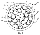
本発明によるコードの例
図2、図3及び図4に、本発明によるコードの第1、第2及び第3の実施形態の例を一般参照符号30で示す。コード30は金属製であり、円筒層を有するタイプのものである。コード30は非コンパクトタイプのものであり、すなわちコード30を構成するスレッドの層の各々は、少なくとも1つの他の層のものとは異なる巻きピッチ及び/又は巻き方向を有する。
Examples of Codes According to the Invention In FIGS. 2, 3 and 4, examples of first, second and third embodiments of codes according to the invention are indicated by the
コード30は、ラッピング層が存在するか否かに関わらず3層タイプのものである。これらのスレッドの層は、隣接して同心円を成す。コード30は、タイヤに一体化されていない時にはゴムを有していない。
The
コード30は、端点を含めて5〜11mmの、好ましくは端点を含めて7〜9mmのピッチp1で螺旋状に巻かれたM本の内部スレッドを含む、この例ではこれらの内部スレッドで構成された内層C1を有し、ここではp1=8mmである。第1、第2及び第3の実施形態では、それぞれMが2、3又は4に等しい。内層C1はコンパクトであり、すなわち内層C1の各スレッドは、内層C1の隣接するスレッドに接触する。内層C1のスレッドは、予備成形されたものではない。
The
コード30は、端点を含めて8〜20mmの、好ましくは端点を含めて12〜18mmのピッチp2で内層C1の周囲に螺旋状に巻かれたN本の中間スレッドを含む、この例ではこれらの中間スレッドで構成された中間層C2も有し、ここではp2=16mmである。Nは、7、8、9又は10に等しく、ここではN=9である。
The
コード30は、端点を含めて12〜30mmの、好ましくは端点を含めて20〜28mmのピッチp3で中間層C2の周囲に螺旋状に巻かれたP本の外部スレッドを含む、この例ではこれらの外部スレッドで構成された外層C3も有し、ここではp3=24mmである。Pは、13、14、15又は16に等しく、14又は15に等しいことが好ましく、ここではP=14である。
The
コード30は、外層C3の周囲にピッチpfで螺旋状に巻かれたラッピングスレッドを含む、この例ではこれらのラッピングスレッドで構成されたラッピング層Cfを有する。ピッチpfは、10mm又はそれ以下であり、8mm又はそれ以下であることが好ましく、6mm又はそれ以下であることがさらに好ましい。ここでは、pf=4mmである。
The
第2及び第3の実施形態(M=3又はM=4)では、コード30が、内層C1のM本のスレッドによって定められた中心キャピラリC0を有する。
In the second and third embodiments (M = 3 or M = 4), the
各層C1、C2、C3、Cfは、コード上で測定した実際の半径に対応するそれぞれの半径R1、R2、R3のそれぞれの円筒状の輪郭E1、E2、E3、Efを対応する層C1、C2、C3、Cfにもたらす実質的に管状のエンベロープを有する。 Each layer C1, C2, C3, Cf has a respective cylindrical contour E1, E2, E3, Ef of the respective radius R1, R2, R3 corresponding to the actual radius measured on the cord and the corresponding layer C1, C2 , C3, Cf with a substantially tubular envelope.
比率p1/p2は、端点を含めて0.4〜0.8であり、端点を含めて0.5〜0.7であることが好ましい。ここでは、p1/p2=0.67である。比率p2/p3は、端点を含めて0.5〜0.9であり、端点を含めて0.6〜0.8であることが好ましい。ここでは、p2/p3=0.75である。 The ratio p1 / p2 is 0.4 to 0.8 including the end points, and preferably 0.5 to 0.7 including the end points. Here, p1 / p2 = 0.67. The ratio p2 / p3 is 0.5 to 0.9 including the end points, and preferably 0.6 to 0.8 including the end points. Here, p2 / p3 = 0.75.
これらの例では、層のスレッドの巻き方向が全て同一であり、すなわちS方向(「S/S/S」構成)、又はZ方向(「Z/Z/Z」構成)のいずれかである。ラッピング層Cfのスレッドの巻き方向は、外層C3のスレッドの巻き方向と異なる。 In these examples, the thread winding directions of the layers are all the same, ie either in the S direction (“S / S / S” configuration) or in the Z direction (“Z / Z / Z” configuration). The thread winding direction of the wrapping layer Cf is different from the thread winding direction of the outer layer C3.
層C1、C2、C3の各スレッドは、端点を含めて0.15〜0.50mmの、好ましくは端点を含めて0.22〜0.50mmの、より好ましくは0.25mm〜0.5mmの、さらに好ましくは端点を含めて0.3〜0.4mmのそれぞれの直径d1、d2、d3を有する。 Each thread of the layers C1, C2, C3 is 0.15 to 0.50 mm including the end points, preferably 0.22 to 0.50 mm including the end points, more preferably 0.25 mm to 0.5 mm. More preferably, the diameters d1, d2, and d3 are 0.3 to 0.4 mm including the end points.
同じ層C1、C2、C3の全てのスレッドは、同じ直径を有することが好ましい。代替例としては、同じ層の少なくとも2つのスレッドが、2つの異なる直径を有する。各内層C1、中間層C2及び外層C3の各スレッドの各直径d1、d2、d3は、d1>d2、d1>d3及びd2=d3をそれぞれ満たす。従って、各直径d1、d2、d3は、d1=0.35mm、d2=d3=0.30mmのようなものである。ラッピング層Cfのスレッドの直径dfは、端点を含めて0.10〜0.26mmであり、ここではdf=0.15mmである。 All threads of the same layer C1, C2, C3 preferably have the same diameter. As an alternative, at least two threads of the same layer have two different diameters. The diameters d1, d2, and d3 of the threads of the inner layer C1, the intermediate layer C2, and the outer layer C3 satisfy d1> d2, d1> d3, and d2 = d3, respectively. Accordingly, the diameters d1, d2, and d3 are such that d1 = 0.35 mm and d2 = d3 = 0.30 mm. The diameter df of the thread of the wrapping layer Cf is 0.10 to 0.26 mm including the end points, and here, df = 0.15 mm.
比率d1/d2は、1又はそれ以上であることが好ましい。この特定の例では、d1/d2が、端点を含めて1.05〜1.3であり、端点を含めて1.10〜1.3であることが好ましく、端点を含めて1.15〜1.3であることがさらに好ましい。ここでは、d1/d2=1.17である。各中間層C2及び外層C3では、コードの主軸に垂直なコードの断面において、少なくとも2つの隣接するスレッドが、ゴムが通過できるようにチャネルP2、P3によってそれぞれ分離される。同じ層C2、C3の2つの隣接するスレッドは、これらの2つの隣接するスレッドを隔てる最短距離として定められるスレッド間距離D2、D3だけ、各層C2、C3において平均的に分離される。D2は、25μm又はそれ以上である。D2は、30μmであることが有利であり、40μmであることが好ましく、50μm又はそれ以上であることがさらに好ましい。D3は、25μm又はそれ以上である。D3は、30μmであることが有利であり、40μmであることが好ましく、50μm又はそれ以上であることがさらに好ましい。また、各スレッド間距離D2、D3は、100μm又はそれ以下である。 The ratio d1 / d2 is preferably 1 or more. In this specific example, d1 / d2 is 1.05-1.3 including the end points, preferably 1.10-1.3 including the end points, and 1.15 including the end points. More preferably, it is 1.3. Here, d1 / d2 = 1.17. In each intermediate layer C2 and outer layer C3, in a cross section of the cord perpendicular to the main axis of the cord, at least two adjacent threads are separated by channels P2, P3, respectively, so that rubber can pass through. Two adjacent threads in the same layer C2, C3 are separated on average in each layer C2, C3 by an inter-thread distance D2, D3, defined as the shortest distance separating these two adjacent threads. D2 is 25 μm or more. D2 is advantageously 30 μm, preferably 40 μm, more preferably 50 μm or more. D3 is 25 μm or more. D3 is advantageously 30 μm, preferably 40 μm, more preferably 50 μm or more. Further, the distances D2 and D3 between the threads are 100 μm or less.
層当たりのスレッド数n(ここではN又はP)、スレッド間距離Di、検討する層(中間層又は外層)のエンベロープの実際の半径Ri、及び検討する層のスレッドの直径di(d2又はd3)は、各検討する層(i=2又は3)毎に、関係式:Di=(2.(1−cos(2π/n))0.5.(Ri−di/2)−diを満たす。値Riは、コードの異なる部分で測定した10個の測定値の平均であることが好ましい。 The number of threads per layer n (N or P in this case), the inter-thread distance Di, the actual radius Ri of the envelope of the layer under consideration (intermediate or outer layer), and the diameter di (d2 or d3) of the thread of the layer under consideration Satisfies the relational expression: Di = (2. (1-cos (2π / n)) 0.5 . (Ri−di / 2) −di for each layer to be examined (i = 2 or 3). Is preferably the average of 10 measurements taken at different parts of the cord.
比率D2/D3は、端点を含めて0.5〜1.5であることが好ましく、端点を含めて0.7〜1.3であることが好ましく、端点を含めて0.8〜1.2であることがさらに好ましく、端点を含めて0.9〜1.1であることがさらに好ましい。 The ratio D2 / D3 is preferably 0.5 to 1.5 including the end points, preferably 0.7 to 1.3 including the end points, and 0.8 to 1. It is more preferable that it is 2, and it is further more preferable that it is 0.9-1.1 including an end point.
層C1、C2、C3及びCfのスレッドは、真鍮でコーティングした炭素鋼製であることが好ましい。炭素鋼スレッドは、例えば機械ワイヤ(直径5〜6mm)から開始して、まず最初に約1mmの中間直径まで圧延及び/又は線引きすることによって加工硬化する既知の方法で作成される。コード10に用いられる鋼鉄は、炭素含有量が約0.92%であり、約0.2%のクロムを含み、残りが鉄と、鋼鉄の製造法に伴う不可避的不純物とで構成された鋼鉄である。代替例としては、炭素含有量が0.7%の鋼鉄が使用される。中間直径のスレッドは、脱脂及び/又は剥離処理され、その後に後続の変換を受ける。これらの中間スレッドに真鍮のコーティングを施した後、例えば水性分散液又は水性乳液の形をとる伸線潤滑剤を用いて湿潤環境において低温延伸することにより、各スレッドに「最終」加工硬化作業と呼ばれるもの(すなわち、最後のパテンティング熱処理後に行うもの)を実行する。スレッドを取り囲む真鍮コーティングは、鋼鉄スレッドの直径に比べれば無視できるほどの、1ミクロンをはるかに下回る、例えば0.15〜0.30μm程度の非常にわずかな厚みである。当然ながら、スレッドの鋼鉄の組成は、その様々な元素(例えばC、Cr、Mn)の面で開始ワイヤの鋼鉄の組成と同じものである。
The threads of the layers C1, C2, C3 and Cf are preferably made of carbon steel coated with brass. Carbon steel threads are made in a known manner, for example starting from machine wires (diameter 5-6 mm) and first work hardened by rolling and / or drawing to an intermediate diameter of about 1 mm. The steel used for the
本明細書で上述した各実施形態の特徴を以下の表1にまとめる。

第1の実施形態(実施例1)によるコード30、及びこのコードをM=2として他の特徴を付随的に同じにした別の形態のいくつかの特徴を表2〜4にまとめた。
第2の実施形態(実施例2)によるコード30、及びこのコードをM=3として他の特徴を付随的に同じにした別の形態のいくつかの特徴を表5〜9にまとめた。
第3の実施形態(実施例3)によるコード30、及びこのコードをM=4として他の特徴を付随的に同じにした別の形態のいくつかの特徴を表10〜14にまとめた。
本発明によるコード及びタイヤの製造方法
次に、本発明によるコードの製造方法について説明する。
Next, the cord manufacturing method according to the present invention will be described.
金属スレッド又はストランドの組み立てには、以下の2つの方法が可能であることが予め想起されるであろう。
− ケーブリングによるもの:この場合、スレッド又はストランドは組み立て地点の前後で同期回転するのでツイスティングを受けない。
− ツイスティングによるもの:この場合、スレッド又はストランドは、その軸を中心にして一括ツイスティング及び個別ツイスティングを受け、従ってスレッド又はストランドの各々に非ツイスト性トルクが生じる。
It will be recalled in advance that the following two methods are possible for assembling metal threads or strands.
-By cabling: In this case, the thread or strand rotates synchronously before and after the assembly point and is not subjected to twisting.
-By twisting: in this case, the thread or strand is subjected to batch twisting and individual twisting about its axis, thus creating a non-twisting torque in each thread or strand.
ツイスティングによって内層C1のM本のスレッドを組み立てる第1のステップでは、「第1の組み立て地点」と呼ばれる第1の地点において第1の層C1を形成する。スレッドは、組み立てガイドに結合されていることも又はいないこともあるスプール、分離グリッドなどの供給手段によって給送され、これらは全て、M本のスレッドを第1の組み立て地点において合流させるように意図される。 In the first step of assembling the M threads of the inner layer C1 by twisting, the first layer C1 is formed at a first point called “first assembly point”. The threads are fed by a supply means such as spools, separation grids, which may or may not be coupled to the assembly guide, all of which are intended to join M threads at the first assembly point. Is done.
ツイスティングによって内層C1の周囲に中間層C2のN本のスレッドを組み立てる第2のステップでは、「第2の組み立て地点」と呼ばれる第2の地点においてM+N構造の中間コードC1+C2を形成する。先の内層C1のM本のスレッドと同様に、中間層C2のN本のスレッドは、N本のスレッドを第2の組み立て地点において内層C1の周囲に合流させるように意図された供給手段によって給送される。 In the second step of assembling N threads of the intermediate layer C2 around the inner layer C1 by twisting, an intermediate code C1 + C2 having an M + N structure is formed at a second point called “second assembly point”. Like the M threads of the inner layer C1, the N threads of the intermediate layer C2 are fed by a supply means intended to join the N threads around the inner layer C1 at the second assembly point. Sent.
ツイスティングによって中間層C2の周囲に外層C3のP本のスレッドを組み立てる第3のステップでは、「第3の組み立て地点」と呼ばれる第3の地点においてM+N+P構造の中間コードC1+C2+C3を形成する。代替例として、この第3のステップは、中間層C3の周囲にケーブリングによって外層C3のP本のスレッドを組み立てる方法を用いることもできる。先の内層及び中間層C1、C2のM本、N本のスレッドと同様に、外層C3のP本のスレッドは、P本のスレッドを第3の組み立て地点において中間層C2の周囲に合流させるように意図された供給手段によって給送される。 In the third step of assembling the P threads of the outer layer C3 around the intermediate layer C2 by twisting, an intermediate code C1 + C2 + C3 having an M + N + P structure is formed at a third point called a “third assembly point”. As an alternative, this third step can also use a method of assembling P threads of the outer layer C3 by cabling around the intermediate layer C3. Similar to the M and N threads of the previous inner layer and intermediate layers C1, C2, the P threads of the outer layer C3 cause the P threads to merge around the intermediate layer C2 at the third assembly point. Is fed by the intended feeding means.
好ましい第4のステップでは、コード30のツイストのバランスをとる。このステップ中、コード30は、ツイストバランスが取れていると言われる(すなわち、実質的に残留捩れのない)コードを得るためにツイストバランシング手段に通され、ここで、「ツイストバランシング」手段が、それぞれの層におけるツイスト状態にあるコードの各スレッドに加わる残留ツイスト性トルク(又は非ツイスト性弾性復帰)を既知の方法で打ち消す。ツイストバランシング手段は、ツイスティングの当業者に周知である。これらの手段は、例えばツイスター、ツイスターストレイテナーなどの回転バランシング手段、又は例えばストレイテナーなどの非回転手段を含み、ツイスターの場合にはプーリで、又はストレイテナーの場合には小径ローラーで構成され、コードは、回転手段の場合には単一平面で、又は非回転手段の場合には少なくとも2つの異なる平面でこれらのプーリ又はローラーを通過する。
In the preferred fourth step, the twist of the
最後に、第5の組み立てステップにおいて、中間コードC1+C2+C3の周囲にラッピング層Cfのスレッドを巻きつける。 Finally, in the fifth assembly step, the thread of the wrapping layer Cf is wound around the intermediate cord C1 + C2 + C3.
代替例として、第1、第2及び第3のステップをケーブリングによって行うこともできる。 As an alternative, the first, second and third steps can also be performed by cabling.
上述したコード30は、この本明細書で上述した方法を用いて得ることができる。
The
次に、本発明によるタイヤの製造方法について説明する。 Next, the tire manufacturing method according to the present invention will be described.
コード30は、ラジアルタイヤのクラウン補強体におけるワーキングプライを製造するための従来の方法で使用される補強材を用いて、カレンダリングによって天然ゴム及びカーボンブラックベースの既知の組成物に組み込まれる。この組成物は、基本的に、エラストマ及び補強材(カーボンブラック)に加え、酸化防止剤、ステアリン酸、伸張オイル、接着促進剤を介したナフテン酸コバルト、そして最後に加硫システム(硫黄、硬化促進剤、ZnO)を含む。このようにして、ゴムマトリックスに組み込まれた1又はそれ以上のコード30を含む複合ファブリックが形成される。このゴムマトリックスは、コードのそれぞれの側に重なり合った、端点を含めて0.3mm〜1.4mmのそれぞれの厚みを有する2つの薄いゴム層で形成される。カレンダリングピッチ(コードがゴムマトリックス内に配置されるピッチ)は、端点を含めて2mm〜4mmである。
The
その後、これらの複合ファブリックは、タイヤの製造方法中にクラウン補強体におけるワーキングプライとして使用され、この方法のステップも当業者に周知である。 These composite fabrics are then used as working plies in the crown reinforcement during the tire manufacturing process, the steps of which are also well known to those skilled in the art.
比較試験及び測定
本発明によるコードのいくつかの実施形態を、直径df=0.15mmのラッピングスレッドを含むラッピング層を有する(1+6)×0.23+6×(1+6)×0.23の構造の49.23FRとして知られている先行技術のストランドコードと比較した。
Comparative Testing and Measurements Some embodiments of the cords according to the present invention have a (1 + 6) × 0.23 + 6 × (1 + 6) × 0.23 construction of 49 with a wrapping layer comprising a wrapping thread with a diameter df = 0.15 mm. .Compared to a prior art strand cord known as .23FR.
本発明による実施例1’、3’のコードと、本発明による実施例1、3のコード(表2及び表12を参照)とは、中間層及び外層の巻き方向のみが異なる。巻き方向はD2及びD3の値に影響しないので、実施例1’及び3’も先行例と比較することができる。 The cords of Examples 1 'and 3' according to the present invention and the cords of Examples 1 and 3 according to the present invention (see Tables 2 and 12) differ only in the winding direction of the intermediate layer and the outer layer. Since the winding direction does not affect the values of D2 and D3, Examples 1 'and 3' can also be compared with the previous example.
動力計測定
ISO6892、1984規格に従う張力下で、Fr(Nにおける最大負荷)で示す破断荷重測定を行った。以下の表15に、得られた破断荷重Frの結果を示す。破断荷重Frは、先行技術のコードの破断荷重に対する相対的単位(U.R)で示している。Frが1U.Rよりも高い時には、試験したコードの破断荷重の方が先行技術のコードの破断荷重よりも高い。逆に、Frが1U.Rよりも低い時には、試験したコードの破断荷重の方が先行技術のコードの破断荷重よりも低い。
本発明によるコードは、先行技術のコードよりも高い破断荷重を有しており、従ってタイヤの耐久性を向上させる。 The cord according to the present invention has a higher breaking load than the prior art cord, thus improving the durability of the tire.
実施例3及び3’からは、外層のスレッドの巻き方向が中間層のスレッドの巻き方向と異なる場合には、内層、中間層及び外層のスレッドの巻き方向が全て同じ場合よりも破断荷重Frが低いことが分かる。 From Examples 3 and 3 ′, when the winding direction of the threads of the outer layer is different from the winding direction of the threads of the intermediate layer, the breaking load Fr is higher than when the winding directions of the threads of the inner layer, the intermediate layer, and the outer layer are all the same. It turns out that it is low.
透気度試験
この試験では、所与の期間にわたって一定の圧力下で試験片に沿って進む空気の体積を測定することにより、試験したコードの長手方向の空気透過性を判定することができる。当業者には周知であるが、このような試験の背後にある原理は、空気不透過性にした時のコードの処理の有効性を実証するというものであり、ASTM D2692−98規格に記載されている。
Air Permeability Test In this test, the longitudinal air permeability of the tested cord can be determined by measuring the volume of air traveling along the specimen under a certain pressure over a given period of time. As is well known to those skilled in the art, the principle behind such a test is to demonstrate the effectiveness of the processing of the code when rendered air impermeable and is described in the ASTM D2692-98 standard. ing.
ここでは、外側からコーティングゴムと呼ばれるゴムで予めコーティングした製造時のコードを含む試験片に対して試験を行う。このために、各々が3.5mmの厚みを有する未加工状態のジエン系ゴム組成物の2つの層又は「スキム」(80×200mm2つの矩形)間に、互いに平行に配置された一連の10本のコードを配置し、次にこの実体全体をモールド内に固定して、コードの各々を、モールド内に置かれた時に確実に真っ直ぐな状態を保つように締め付けモジュールを用いて十分な張力(例えば2daN)下に保持し、その後、130℃の温度で、100分〜10時間の継続時間にわたり、15barの圧力(80×200mmの矩形ピストン)下で加硫(硬化)処理を行う。その後、実体全体をモールドから除去し、このようにコーティングされた10個のコード試験片を7×7×20mmの平行六面体の形に切り取って特徴付ける。 Here, the test is performed on a test piece including a cord at the time of manufacture which is pre-coated with rubber called coating rubber from the outside. For this purpose, a series of ten pieces arranged parallel to each other between two layers or “skims” (80 × 200 mm two rectangles) of raw diene rubber composition each having a thickness of 3.5 mm. And then secure the entire entity in the mold and use a tightening module to ensure that each of the cords is kept straight when placed in the mold. 2 da N), followed by a vulcanization (curing) treatment at a temperature of 130 ° C. under a pressure of 15 bar (80 × 200 mm rectangular piston) for a duration of 100 minutes to 10 hours. Thereafter, the entire entity is removed from the mold and the ten cord specimens thus coated are cut and characterized in the form of 7 × 7 × 20 mm parallelepipeds.
コーティングゴムとしては、天然(素練り)ゴム及びカーボンブラックN330(65phr)をベースとして、硫黄(7phr)、スルホンアミド硬化促進剤(1phr)、ZnO(8phr)、ステアリン酸(0.7phr)、酸化防止剤(1.5phr)、ナフテン酸コバルト(1.5phr)(phrは、ゴム100部当たりの重量部を意味する)という通常の添加剤も含む、従来タイヤに使用されているジエン系ゴム組成物を使用し、コーティングゴムのE10係数は約10MPaである。 The coating rubber is based on natural (kneaded) rubber and carbon black N330 (65 phr), sulfur (7 phr), sulfonamide curing accelerator (1 phr), ZnO (8 phr), stearic acid (0.7 phr), oxidation Diene rubber composition used in conventional tires, which also includes conventional additives such as inhibitor (1.5 phr), cobalt naphthenate (1.5 phr) (phr means parts by weight per 100 parts of rubber) The E10 coefficient of the coating rubber is about 10 MPa.
試験は、硬化状態にある周囲のゴム組成物(又はコーティングゴム)によってこのようにコーティングされた4cm長のコードに対し、コードの入口端部に1barの圧力で空気を注入し、(例えば0〜500cm3/分に較正した)流量計を用いて出口端部の空気の体積を測定するという方法で行う。測定中には、コードの一端からその長手方向軸に沿って他端に通過する空気の量のみが測定において考慮されるように、コードの試験片を圧縮気密シール(例えば、高密度の発泡体又はゴム製のシール)内に固定し、固体ゴム試験片、すなわちコードを含んでいないものを用いて事前に空気シール自体の気密性をチェックする。 The test consists in injecting air at a pressure of 1 bar at the inlet end of the cord for a 4 cm long cord thus coated with the surrounding rubber composition (or coating rubber) in the cured state (e.g. 0 to 0). This is done by measuring the air volume at the outlet end using a flow meter (calibrated to 500 cm 3 / min). During the measurement, the cord specimen is compressed and hermetically sealed (eg, a high-density foam) so that only the amount of air passing from one end of the cord along its longitudinal axis to the other is considered in the measurement. (Or a rubber seal), and the air seal itself is checked for airtightness in advance using a solid rubber specimen, ie, one that does not contain a cord.
コードの長手方向不浸透性が高ければ高いほど、(10個の試験片にわたって平均化した)測定される平均空気流量Dmは低くなる。この測定を、±0.2cm3/分の精度で行う。 The higher the longitudinal impermeability of the cord, the lower the measured average air flow Dm (averaged over 10 specimens). This measurement is performed with an accuracy of ± 0.2 cm 3 / min.
この、本明細書で上述した(10回の測定にわたって平均化した)1分間にコードに沿って通過した空気の体積(cm3)を測定することによる透気度試験をコードに対して行う。この結果を以下の表16にまとめる。流量Dmは、先行技術のコードの流量に対する相対的単位(U.R)で示している。Dmが1U.Rよりも高い時には、試験したコードの流量の方が先行技術のコードの流量よりも大きい。逆に、Dmが1U.Rよりも低い時には、試験したコードの流量の方が先行技術のコードの流量よりも小さい。
先行技術では、コードの各ストランドの飽和及びコード自体の飽和によってゴムの浸透性が制限され、従って各レイヤストランドの各内層と外層の間、及び各レイヤストランド間に数多くの外部キャピラリが形成されるようになる。従って空気、ひいては腐食物質が容易に内部を循環することができる。 In the prior art, the saturation of each strand of cord and the saturation of the cord itself limits the permeability of the rubber, thus forming a number of outer capillaries between each inner and outer layer of each layer strand and between each layer strand. It becomes like this. Therefore, air and thus corrosive substances can easily circulate inside.
先行技術のストランドコードは、コアストランドのスレッド間に内部キャピラリも有する。これらは、外部キャピラリと容易に連通することにより、様々なキャピラリ間に空気、ひいては腐食物質を通過させやすくする。 Prior art strand cords also have an inner capillary between the threads of the core strand. These easily communicate with the external capillaries to facilitate the passage of air and thus corrosive substances between the various capillaries.
本発明によるコードは、その高レベルの不飽和性により、層C1とC2の間にキャピラリがほとんど又は全く存在せず、層C2とC3の間にもキャピラリが存在せず、すなわち空気流量が相対的に低く、先行技術のコードと比べて腐食物質の非伝播性を向上させることができる。 The cord according to the invention, due to its high level of unsaturation, has little or no capillaries between layers C1 and C2, and no capillaries between layers C2 and C3, i.e. relative air flow. And can improve the non-propagating nature of corrosive substances compared to prior art codes.
M=3及びM=4のコード、この例では実施例2、3及び3’は、主に伝播キャピラリとして図3及び図4に示す中心キャピラリC0を有し、先行技術のコードの空気流量と同等の又はそれよりも高い空気流量をもたらす。中心キャピラリC0の断面が大きければ大きいほど、空気流量も高くなる。従って、内層に含まれるスレッドが多ければ多いほど、空気流量も高くなる。しかしながら、この中心キャピラリC0は、残りのコードから隔離されているという利点を有し、従って空気、ひいては腐食物質を内層のスレッド間に閉じ込める。 The codes M = 3 and M = 4, in this example, Examples 2, 3 and 3 ′, have the central capillary C0 shown in FIGS. 3 and 4 mainly as the propagation capillary, and the air flow rate of the prior art code and Provides an equivalent or higher air flow rate. The larger the cross section of the center capillary C0, the higher the air flow rate. Therefore, the more threads contained in the inner layer, the higher the air flow rate. However, this central capillary C0 has the advantage of being isolated from the rest of the cord, thus confining air and thus corrosive substances between the inner layer threads.
なお、M=4のコードでは、外層のスレッドが巻かれる方向が中間層のスレッドの巻かれる方向と異なる時には空気流量が低くなる。 In the M = 4 cord, the air flow rate is low when the direction in which the outer layer thread is wound is different from the direction in which the intermediate layer thread is wound.
接着腐食試験
この試験は、ASTM D2229規格に従って行われる。透気度試験で作成したものと同様の試験片を作成する。試験片の一端を所定の継続時間、この例では21日間にわたって塩水の浴槽に浸漬する。その後、ケーブルのコーティングゴムを引き剥がすのに必要な接着力Faを測定する。腐食物質、この例では塩水によって損なわれた接着界面の度合いが大きければ大きいほど、測定される力は小さい。この結果を表17にまとめる。
Adhesion Corrosion Test This test is performed according to ASTM D2229 standard. Create a test piece similar to that created in the air permeability test. One end of the test piece is immersed in a salt water bath for a predetermined duration, in this example 21 days. Thereafter, the adhesive force Fa necessary for peeling off the coating rubber of the cable is measured. The greater the degree of adhesion interface damaged by the corrosive material, in this case salt water, the less force is measured. The results are summarized in Table 17.
試験したコードの初期力Faは、先行技術のコードの初期力Faと比較して相対的単位(U.R)で示している。試験したコードのFaが1U.Rよりも大きい時には、試験したコードの初期力Faの方が先行技術のコードの初期力Faよりも高い。 The initial force Fa of the tested cord is shown in relative units (UR) compared to the initial force Fa of the prior art cord. The Fa of the tested cord is 1U. When larger than R, the initial force Fa of the tested cord is higher than the initial force Fa of the prior art cord.
試験したコードの21日力Faは、試験したコードの初期力Faと比較して相対的単位(U.R)で示している。この21日力Faが1U.Rよりも小さい時には、試験したコードの21日力Faの方が試験したコードの初期力Faよりも低い。
M=3及びM=4のコード、この例ではコード2、3及び3’は、中心キャピラリC0の存在によって空気流量は先行技術のコードの空気流量よりも高いか、或いは実質的に等しいにも関わらず、接着性能についてはせいぜい先行技術のコードと同程度であろうと予想していた。これとは全く逆に、本発明によるコード、特にM=3及びM=4のコードは、外部及び内部キャピラリが互いに連通して最も外側のスレッドの腐食、従ってコードと隣接するゴムとの間の接着界面の劣化を促進する先行技術のコードとは異なり、腐食物質が浸透した場合に、これらが中心キャピラリC0及び層C1とC2の間に存在し得るいずれかのキャピラリに閉じ込められて、中間層及び外層を全く、又はわずかな程度しか腐食することができないため、隣接するゴムへの接着性が先行技術のコードよりも良好であることを示した。 The codes M = 3 and M = 4, in this example the codes 2, 3 and 3 ′, indicate that the air flow rate is higher or substantially equal to the air flow rate of the prior art code due to the presence of the central capillary C0. Nevertheless, it was expected that the adhesive performance would be at most comparable to the prior art code. In contrast, cords according to the present invention, in particular cords with M = 3 and M = 4, are such that the outer and inner capillaries communicate with each other and corrode the outermost thread, thus between the cord and the adjacent rubber. Unlike prior art codes that promote degradation of the adhesive interface, when corrosive material penetrates, they are confined to the central capillary C0 and any capillary that may exist between layers C1 and C2, and the intermediate layer And the outer layer can be eroded at all or only to a minor extent, indicating better adhesion to adjacent rubber than prior art cords.
従って、Mの値が何であろうと、本発明によるコードは、先行技術のコードの接着力Faよりもはるかに高い接着力Faを示す。本発明によるコードは、腐食物質の直接作用から保護され、中心キャピラリが存在する時にはこのようなキャピラリ内に腐食物質が閉じ込められることによって圧縮強度及び耐久性が向上する。 Therefore, whatever the value of M, the cords according to the present invention exhibit a much higher adhesion force Fa than that of the prior art cords. The cord according to the present invention is protected from the direct action of corrosive substances and, when a central capillary is present, compressive strength and durability are improved by confining the corrosive substances in such capillaries.
コード及び補強プライの質量
所定のプライ破断荷重値、この例では1700daN/cmについて、1m2の補強プライに含まれるコードの質量、及びこの補強プライの質量を計算した。次に、これを用いて、先行技術のコードを含む1m2の補強プライと比較した、1m2のプライのコード及び補強プライに関する重量削減を推定する。これらの削減を以下の表18にまとめる。
先行技術のコードよりも破断荷重が高いことにより、敷設ピッチを増やし、プライ内のコード数を減少させ、従って同時にコードの質量とプライの質量を減少させることができる。 The higher breaking load than the prior art cords can increase the laying pitch and reduce the number of cords in the ply, thus simultaneously reducing the cord mass and the ply mass.
さらに、先行技術のストランドコードよりもコンパクト性が高いことにより、カレンダリングゴムの厚みを減少させ、従ってプライを軽量化することができる。 Furthermore, the higher compactness than prior art strand cords can reduce the thickness of the calendering rubber and thus reduce the weight of the ply.
このように、特にプライの質量に関してタイヤの質量が大幅に軽量化されることによってヒステリシスが低下し、従ってタイヤの転がり抵抗、ひいては燃料消費量が減少する。さらに、コード及びプライの工業原価も低下する。 Thus, hysteresis is reduced by significantly reducing the weight of the tire, particularly with respect to the weight of the ply, thus reducing the rolling resistance of the tire and hence the fuel consumption. In addition, the industrial costs of cords and plies are reduced.
言うまでもなく、本発明は、本明細書で上述した例示的な実施形態に限定されるわけではない。 Of course, the present invention is not limited to the exemplary embodiments described hereinabove.
従って、いくつかのスレッドは非円形断面を有することもでき、例えば実質的に楕円の、又は例えば三角形、正方形又は長方形などの多角形の断面にまで塑性的に変形させることもできる。その場合、各スレッドの直径は、スレッドの断面が内接する円の直径を意味するものとして解釈しなければならない。 Thus, some threads can also have a non-circular cross-section, and can be plastically deformed, for example, to a substantially elliptical or polygonal cross-section such as, for example, a triangle, square or rectangle. In that case, the diameter of each thread should be taken to mean the diameter of the circle in which the cross section of the thread is inscribed.
別の実施形態では、内層のスレッドが真っ直ぐであり、すなわち無限大のピッチを有する。 In another embodiment, the inner layer threads are straight, i.e., have an infinite pitch.
工業的実現可能性、コスト及び全体的性能の理由から、本発明は、従来の円形断面を有する線形の、すなわち真っ直ぐなスレッドを用いて実施することが好ましい。 For reasons of industrial feasibility, cost and overall performance, the present invention is preferably implemented using a linear or straight thread having a conventional circular cross section.
また、内層のスレッドの巻き方向が中間層のスレッドの巻き方向と異なる、例えば、S/Z/S配列、Z/S/Z配列、S/Z/Z配列又はZ/S/S配列のコードなどのコードを検討することも可能なはずである。 Also, the winding direction of the inner layer thread is different from the winding direction of the intermediate layer thread, for example, an S / Z / S array, a Z / S / Z array, an S / Z / Z array, or a Z / S / S array code. It should be possible to consider code such as
P=13の、好ましくはd3>d2のコードを使用することもできる。同様に、P=16の、好ましくはd3<d2の別の実施形態によるコードを使用することもできる。 It is also possible to use a code with P = 13, preferably d3> d2. Similarly, a code according to another embodiment of P = 16, preferably d3 <d2, can be used.
図示した実施形態では、内層がコンパクトでない。 In the illustrated embodiment, the inner layer is not compact.
図示していない別の実施形態では、d2=d1かつd3<d2である。 In another embodiment not shown, d2 = d1 and d3 <d2.
さらに、本発明によるコードは、道路運送車両用のタイヤの、例えばクラウン補強体において、特にワーキングクラウンプライにおいて使用することもできる。 Furthermore, the cords according to the invention can also be used in road tires, for example in crown reinforcements, in particular in working crown plies.
さらに、本発明によるコードは、カーカス補強体を補強することができる。従って、0.15mm≦d1、d2、d3≦0.30mmであるような、より好ましくは0.15mm≦d1、d2、d3≦0.26mmであるようなスレッドを含むコードを使用することも可能である。 Furthermore, the cord according to the present invention can reinforce the carcass reinforcement. Therefore, it is possible to use a cord including a thread such that 0.15 mm ≦ d1, d2, d3 ≦ 0.30 mm, more preferably 0.15 mm ≦ d1, d2, d3 ≦ 0.26 mm. It is.
本発明によるコードは、タイヤの製造を目的としたもの以外のゴムマトリックス、例えばキャタピラトラックを製造するためのゴムマトリックスを補強することもできる。従って、本発明によるコードを含むキャタピラトラックの使用を検討することも可能である。 The cords according to the invention can also reinforce rubber matrices other than those intended for the production of tires, for example rubber matrices for the production of caterpillar tracks. It is therefore possible to consider the use of a caterpillar track comprising a cord according to the invention.
本明細書で説明又は想定した様々な実施形態の特徴は、互いに適合性がある限り組み合わせることもできる。 The features of the various embodiments described or envisaged herein may be combined as long as they are compatible with each other.
中間層のスレッド間のスレッド間距離D2が25μm又はそれ以上であり、外層のスレッド間のスレッド間距離D3が25μm又はそれ以上であるという事実に関わらず、
− M=2本のスレッドを含む内層と、
− 内層の周囲に螺旋状に巻かれたN=7、8、9又は10本のスレッドを含む中間層と、
− 中間層の周囲に螺旋状に巻かれたP=13、14、15又は16本のスレッドを含む外層と、
を含む円筒層付き金属コードの使用を検討することが可能である。
Regardless of the fact that the inter-thread distance D2 between the threads in the middle layer is 25 μm or more and the inter-thread distance D3 between the threads in the outer layer is 25 μm or more,
An inner layer containing M = 2 threads;
-An intermediate layer comprising N = 7, 8, 9 or 10 threads spirally wound around the inner layer;
An outer layer comprising P = 13, 14, 15 or 16 threads spirally wound around the intermediate layer;
It is possible to consider the use of a metal cord with a cylindrical layer containing.
中間層のスレッド間のスレッド間距離D2が25μm又はそれ以上であり、外層のスレッド間のスレッド間距離D3が25μm又はそれ以上であるという事実に関わらず、
− M=3本のスレッドを含む内層と、
− 内層の周囲に螺旋状に巻かれたN=7、8、9又は10本のスレッドを含む中間層と、
− 中間層の周囲に螺旋状に巻かれたP=13、14、15又は16本のスレッドを含む外層と、
を含む円筒層付き金属コードの使用を検討することがさらに可能である。
Regardless of the fact that the inter-thread distance D2 between the threads in the middle layer is 25 μm or more and the inter-thread distance D3 between the threads in the outer layer is 25 μm or more,
An inner layer containing M = 3 threads;
-An intermediate layer comprising N = 7, 8, 9 or 10 threads spirally wound around the inner layer;
An outer layer comprising P = 13, 14, 15 or 16 threads spirally wound around the intermediate layer;
It is further possible to consider the use of a metal cord with a cylindrical layer comprising
最後に、中間層のスレッド間のスレッド間距離D2が25μm又はそれ以上であり、外層のスレッド間のスレッド間距離D3が25μm又はそれ以上であるという事実に関わらず、
− M=4本のスレッドを含む内層と、
− 内層の周囲に螺旋状に巻かれたN=7、8、9又は10本のスレッドを含む中間層と、
− 中間層の周囲に螺旋状に巻かれたP=13、14、15又は16本のスレッドを含む外層と、
を含む円筒層付き金属コードの使用を検討することが可能である。
Finally, regardless of the fact that the inter-thread distance D2 between the threads in the middle layer is 25 μm or more and the inter-thread distance D3 between the threads in the outer layer is 25 μm or more,
An inner layer containing M = 4 threads;
-An intermediate layer comprising N = 7, 8, 9 or 10 threads spirally wound around the inner layer;
An outer layer comprising P = 13, 14, 15 or 16 threads spirally wound around the intermediate layer;
It is possible to consider the use of a metal cord with a cylindrical layer containing.
本明細書で説明したような少なくとも1つの層状の金属コードを基本ストランドとして含むマルチストランドロープコードを検討することも可能である。 It is also possible to consider a multi-strand rope cord comprising at least one layered metal cord as described herein as a basic strand.
10 タイヤ
12 クラウン
14 クラウン補強体
16 サイドウォール部
18 ビード部
20 ビードワイヤ
22 カーカス補強体
24 折り返し部
26 リム
DESCRIPTION OF
Claims (20)
− M本のスレッドから成る内層(C1)と、
− 前記内層(C1)の周囲に螺旋状に巻かれたN本のスレッドから成る中間層(C2)と、
− 前記中間層(C2)の周囲に螺旋状に巻かれたP本のスレッドから成る外層(C3)と、
を含み、前記コードにおいて、
前記中間層(C2)の前記スレッド間のスレッド間距離D2は25μm又はそれ以上であり、前記外層(C3)の前記スレッド間のスレッド間距離D3は25μm又はそれ以上である、
ことを特徴とするコード(30)。 A metal cord (30) with a cylindrical layer,
An inner layer (C1) consisting of M threads;
-An intermediate layer (C2) consisting of N threads spirally wound around the inner layer (C1);
An outer layer (C3) consisting of P threads spirally wound around the intermediate layer (C2);
And in the code,
The inter-thread distance D2 between the threads of the intermediate layer (C2) is 25 μm or more, and the inter-thread distance D3 between the threads of the outer layer (C3) is 25 μm or more.
A code (30) characterized by that.
ことを特徴とする請求項1に記載のコード(30)。 The inter-thread distance D2 between the threads of the intermediate layer (C2) is 30 μm or more, preferably 40 μm, more preferably 50 μm.
The cord (30) according to claim 1, characterized in that:
ことを特徴とする請求項1又は2に記載のコード(30)。 The inter-thread distance D3 between the threads of the outer layer (C3) is 30 μm or more, preferably 40 μm, more preferably 50 μm.
The cord (30) according to claim 1 or 2, characterized in that
ことを特徴とする請求項1から3のいずれか1項に記載のコード(30)。 The inter-thread distance D2 between the threads of the intermediate layer (C2) is 100 μm or less.
The cord (30) according to any one of claims 1 to 3, characterized in that:
ことを特徴とする請求項1から4のいずれか1項に記載のコード(30)。 The inter-thread distance D3 between the threads of the outer layer (C3) is 100 μm or less.
The cord (30) according to any one of claims 1 to 4, characterized in that:
ことを特徴とする請求項1から5のいずれか1項に記載のコード(30)。 The ratio D2 / D3 satisfies 0.5 ≦ D2 / D3 ≦ 1.5, preferably satisfies 0.7 ≦ D2 / D3 ≦ 1.3, more preferably 0.8 ≦ D2 / D3 ≦ 1.2. More preferably 0.9 ≦ D2 / D3 ≦ 1.1,
A cord (30) according to any one of the preceding claims, characterized in that
ことを特徴とする請求項1から6のいずれか1項に記載のコード(30)。 M = 2, 3 or 4, N = 7, 8, 9 or 10, and P = 13, 14, 15 or 16.
A cord (30) according to any one of the preceding claims, characterized in that
ことを特徴とする請求項5に記載のコード(30)。 P = 14 or 15.
The cord (30) according to claim 5, characterized in that.
ことを特徴とする請求項5に記載のコード(30)。 M = 2, N = 7, 8, 9 or 10, and P = 13, 14, 15 or 16, preferably M = 2, N = 7, 8 or 9, and P = 14, more preferably M = 2, N = 9, and P = 14.
The cord (30) according to claim 5, characterized in that.
ことを特徴とする請求項5に記載のコード(30)。 M = 3, N = 7, 8, 9 or 10, and P = 13, 14, 15 or 16, preferably M = 3, N = 8 or 9, and P = 14 or 15. M = 3, N = 9 and P = 14,
The cord (30) according to claim 5, characterized in that.
ことを特徴とする請求項5に記載のコード(30)。 M = 4, N = 7, 8, 9 or 10 and P = 13, 14, 15 or 16, preferably M = 4, N = 7, 8, 9 or 10 and P = 14 or 15. More preferably M = 4, N = 9 and P = 14.
The cord (30) according to claim 5, characterized in that.
ことを特徴とする請求項1から11のいずれか1項に記載のコード(30)。 The diameters d1, d2, d3 of the threads of each inner layer (C1), intermediate layer (C2) and outer layer (C3) satisfy 0.15 ≦ d1, d2, d3 ≦ 0.5 mm, respectively, preferably 0 .22 ≦ d1, d2, d3 ≦ 0.5 mm is satisfied, more preferably 0.25 ≦ d1, d2, d3 ≦ 0.5 mm is satisfied, and still more preferably 0.30 ≦ d1, d2, d3 ≦ 0.4 mm. Meet,
12. A cord (30) according to any one of the preceding claims, characterized in that
ことを特徴とする請求項1から12のいずれか1項に記載のコード(30)。 The diameters d1 and d2 of the threads of the inner layer (C1) and the intermediate layer (C2) satisfy d1 / d2> 1, respectively, preferably satisfy 1.05 ≦ d1 / d2 ≦ 1.3, and more preferably Satisfies 1.10 ≦ d1 / d2 ≦ 1.3 mm, more preferably 1.15 ≦ d1 / d2 ≦ 1.3 mm.
13. A cord (30) according to any one of the preceding claims, characterized in that
ことを特徴とする請求項1から13のいずれか1項に記載のコード(30)。 The diameters d1, d2, and d3 of the threads of each inner layer (C1), intermediate layer (C2), and outer layer (C3) satisfy d1> d2 and / or d1> d3, respectively.
14. A cord (30) according to any one of the preceding claims, characterized in that
ことを特徴とする請求項1から14のいずれか1項に記載のコード(30)。 The diameters d2 and d3 of the threads of the intermediate layer (C2) and the outer layer (C3) satisfy d2 = d3, respectively.
15. A cord (30) according to any one of the preceding claims, characterized in that
ことを特徴とする請求項1から15のいずれか1項に記載のコード(30)。 The winding direction of the thread of the outer layer (C3) is different from the winding direction of the thread of the intermediate layer (C2).
A cord (30) according to any one of the preceding claims, characterized in that
ことを特徴とする請求項1から16のいずれか1項に記載のコード(30)。 The threads of the inner layer (C1) are not preformed;
Code (30) according to any one of the preceding claims, characterized in that.
ことを特徴とするマルチストランドロープコード。 Comprising at least one cylindrical layered metal cord (30) according to any one of claims 1 to 17 as basic strands,
A multi-strand rope cord.
ことを特徴とするタイヤ(10)。 A metal cord (30) with at least one cylindrical layer according to any one of claims 1 to 17, or a multi-strand rope cord according to claim 18.
A tire (10) characterized by that.
ことを特徴とするキャタピラトラック。 A metal cord (30) with at least one cylindrical layer according to any one of claims 1 to 17, or a multi-strand rope cord according to claim 18.
A caterpillar truck characterized by that.
Applications Claiming Priority (3)
| Application Number | Priority Date | Filing Date | Title |
|---|---|---|---|
| FR1262088 | 2012-12-14 | ||
| FR1262088A FR2999614B1 (en) | 2012-12-14 | 2012-12-14 | METAL CABLE WITH HIGH PENETRABILITY LAYERS |
| PCT/EP2013/076561 WO2014090996A2 (en) | 2012-12-14 | 2013-12-13 | Steel cord comprising layers having high penetrability |
Publications (2)
| Publication Number | Publication Date |
|---|---|
| JP2016504502A true JP2016504502A (en) | 2016-02-12 |
| JP2016504502A5 JP2016504502A5 (en) | 2016-11-24 |
Family
ID=47989116
Family Applications (1)
| Application Number | Title | Priority Date | Filing Date |
|---|---|---|---|
| JP2015547049A Pending JP2016504502A (en) | 2012-12-14 | 2013-12-13 | Metal cord with a highly permeable layer |
Country Status (7)
| Country | Link |
|---|---|
| US (1) | US20150329995A1 (en) |
| EP (1) | EP2931966A2 (en) |
| JP (1) | JP2016504502A (en) |
| KR (1) | KR20150094727A (en) |
| CN (1) | CN104854274B (en) |
| FR (1) | FR2999614B1 (en) |
| WO (1) | WO2014090996A2 (en) |
Cited By (2)
| Publication number | Priority date | Publication date | Assignee | Title |
|---|---|---|---|---|
| WO2018203504A1 (en) * | 2017-05-02 | 2018-11-08 | 横浜ゴム株式会社 | Bead ring and method for manufacturing same |
| JP2021527766A (en) * | 2018-06-20 | 2021-10-14 | コンパニー ゼネラール デ エタブリッスマン ミシュラン | Bilayer multi-strand cord with improved penetration |
Families Citing this family (15)
| Publication number | Priority date | Publication date | Assignee | Title |
|---|---|---|---|---|
| FR3020016B1 (en) | 2014-04-22 | 2016-04-01 | Michelin & Cie | PNEUMATIC FOR HEAVY INDUSTRIAL VEHICLE |
| FR3020017B1 (en) | 2014-04-22 | 2017-06-09 | Michelin & Cie | PNEUMATIC VEHICLE FOR CIVIL ENGINEERING |
| FR3032978B1 (en) | 2015-02-19 | 2017-10-27 | Michelin & Cie | MULTITORON 1XN STRUCTURE CABLE FOR PNEUMATIC PROTECTION FRAME |
| FR3017885A1 (en) * | 2015-06-16 | 2015-08-28 | Michelin & Cie | MULTI-TORON METAL CABLE |
| FR3060617A1 (en) | 2016-12-20 | 2018-06-22 | Compagnie Generale Des Etablissements Michelin | MULTI-TORON CABLE WITH TWO LAYERS WITH IMPROVED PENETRABILITY |
| FR3060616A1 (en) | 2016-12-20 | 2018-06-22 | Compagnie Generale Des Etablissements Michelin | MULTI-TORON CABLE WITH TWO LAYERS WITH IMPROVED PENETRABILITY |
| JP6865273B2 (en) | 2017-04-28 | 2021-04-28 | 株式会社ブリヂストン | Steel cord for reinforcing rubber articles, its manufacturing method and tires |
| CN107268309A (en) * | 2017-06-21 | 2017-10-20 | 盛利维尔(中国)新材料技术股份有限公司 | A kind of load-carrying tire carcass steel cord with 2+7+13 structures |
| US11319666B2 (en) * | 2017-12-19 | 2022-05-03 | Compagnie Generale Des Etablissements Michelin | Two-layer multi-strand cords having very low, low and medium moduli |
| AU2019291195A1 (en) * | 2018-06-20 | 2021-01-21 | Compagnie Generale Des Etablissements Michelin | Double-layer multi-strand cord with improved penetrability |
| WO2019243688A1 (en) * | 2018-06-20 | 2019-12-26 | Compagnie Generale Des Etablissements Michelin | Double-layer multi-strand cord with improved penetrability |
| JP7345510B2 (en) * | 2018-06-20 | 2023-09-15 | コンパニー ゼネラール デ エタブリッスマン ミシュラン | Double layer multi-strand cord with improved penetration |
| CN110904703A (en) * | 2019-09-28 | 2020-03-24 | 海盐宏拓五金有限公司 | Steel wire rope for concrete prefabricated high-strength metal connecting piece and production method thereof |
| CN112359623A (en) * | 2020-11-17 | 2021-02-12 | 江苏兴达钢帘线股份有限公司 | Steel wire cord for improving glue layer infiltration |
| CN112359622A (en) * | 2020-11-17 | 2021-02-12 | 江苏兴达钢帘线股份有限公司 | Outer unsaturated steel wire cord |
Citations (5)
| Publication number | Priority date | Publication date | Assignee | Title |
|---|---|---|---|---|
| JPS5450640A (en) * | 1977-07-07 | 1979-04-20 | Bekaert Sa Nv | Metal cord |
| JPH0544183A (en) * | 1991-01-31 | 1993-02-23 | Sumitomo Rubber Ind Ltd | Steel cord |
| JPH05156580A (en) * | 1991-12-05 | 1993-06-22 | Bridgestone Bekaert Steel Code Kk | Rubber good-reinforcing steel cord and its production |
| JPH07109684A (en) * | 1993-10-08 | 1995-04-25 | Bridgestone Corp | Steel cord for reinforcing rubber product and pneumatic radial tire |
| JP2009293149A (en) * | 2008-06-05 | 2009-12-17 | Bridgestone Corp | Steel cord for reinforcing rubber article, and pneumatic radial tire using the same |
Family Cites Families (19)
| Publication number | Priority date | Publication date | Assignee | Title |
|---|---|---|---|---|
| US4781016A (en) * | 1987-02-16 | 1988-11-01 | Bridgestone Corporation | Steel cords |
| JPH0672370B2 (en) * | 1989-02-27 | 1994-09-14 | 住友ゴム工業株式会社 | Steel cord |
| US5285836A (en) * | 1991-01-31 | 1994-02-15 | Sumitomo Rubber Industries, Ltd. | 3+7+13 steel cord and tire including same |
| JPH05148779A (en) * | 1991-11-28 | 1993-06-15 | Sumitomo Rubber Ind Ltd | Steel codes |
| JP3538205B2 (en) * | 1992-03-09 | 2004-06-14 | 住友ゴム工業株式会社 | Steel cord for tire carcass, steel cord for tire filler, and tire using the same |
| US5806296A (en) * | 1995-05-26 | 1998-09-15 | Bridgestone Metalpha Corporation | Corrosion resistant spiral steel filament and steel cord made therefrom |
| JP3213698B2 (en) * | 1997-04-23 | 2001-10-02 | 東京製綱株式会社 | Steel cord and steel radial tire |
| KR100296075B1 (en) * | 1999-03-05 | 2001-07-03 | 조충환 | A rubber and a steel cord for reinforcement of a tire with increased rubber penetration |
| FR2795751A1 (en) * | 1999-06-29 | 2001-01-05 | Michelin Soc Tech | MULTILAYER STEEL CABLE FOR PNEUMATIC CARCASS |
| JP4705302B2 (en) * | 1999-12-30 | 2011-06-22 | ソシエテ ド テクノロジー ミシュラン | Multi-layer steel cable for tire carcass |
| JP2004527666A (en) * | 2001-01-04 | 2004-09-09 | ソシエテ ド テクノロジー ミシュラン | Multilayer steel cable for tire crown reinforcement |
| EP1349984A1 (en) * | 2001-01-04 | 2003-10-08 | Société de Technologie Michelin | Multi-layered steel cord for a tyre crown reinforcement |
| WO2005014924A1 (en) * | 2003-07-17 | 2005-02-17 | N.V. Bekaert S.A. | Open layered steel cord with high breaking load |
| WO2009048054A1 (en) * | 2007-10-11 | 2009-04-16 | Bridgestone Corporation | Steel cord for rubber article reinforcement and pneumatic tire using the steel cord |
| JP4340314B2 (en) * | 2007-11-27 | 2009-10-07 | 住友ゴム工業株式会社 | Pneumatic tire |
| FR2938558B1 (en) * | 2008-11-17 | 2010-12-31 | Michelin Soc Tech | METHOD AND DEVICE FOR MANUFACTURING A THREE LAYER CABLE OF THE TYPE IN SITU GUM. |
| FR2947576B1 (en) * | 2009-07-03 | 2011-08-19 | Michelin Soc Tech | METAL CABLE WITH THREE LAYERS GUM IN SITU CONSTRUCTION 2 + M + N |
| CN202347188U (en) * | 2011-08-13 | 2012-07-25 | 江苏兴达钢帘线股份有限公司 | Twenty-seven bundles of steel cords |
| CN202347189U (en) * | 2011-11-09 | 2012-07-25 | 江苏兴达钢帘线股份有限公司 | Twenty seven-strand steel cord |
-
2012
- 2012-12-14 FR FR1262088A patent/FR2999614B1/en not_active Expired - Fee Related
-
2013
- 2013-12-13 US US14/651,713 patent/US20150329995A1/en not_active Abandoned
- 2013-12-13 CN CN201380064773.XA patent/CN104854274B/en active Active
- 2013-12-13 WO PCT/EP2013/076561 patent/WO2014090996A2/en active Application Filing
- 2013-12-13 EP EP13803069.7A patent/EP2931966A2/en not_active Withdrawn
- 2013-12-13 KR KR1020157018469A patent/KR20150094727A/en not_active Application Discontinuation
- 2013-12-13 JP JP2015547049A patent/JP2016504502A/en active Pending
Patent Citations (5)
| Publication number | Priority date | Publication date | Assignee | Title |
|---|---|---|---|---|
| JPS5450640A (en) * | 1977-07-07 | 1979-04-20 | Bekaert Sa Nv | Metal cord |
| JPH0544183A (en) * | 1991-01-31 | 1993-02-23 | Sumitomo Rubber Ind Ltd | Steel cord |
| JPH05156580A (en) * | 1991-12-05 | 1993-06-22 | Bridgestone Bekaert Steel Code Kk | Rubber good-reinforcing steel cord and its production |
| JPH07109684A (en) * | 1993-10-08 | 1995-04-25 | Bridgestone Corp | Steel cord for reinforcing rubber product and pneumatic radial tire |
| JP2009293149A (en) * | 2008-06-05 | 2009-12-17 | Bridgestone Corp | Steel cord for reinforcing rubber article, and pneumatic radial tire using the same |
Cited By (5)
| Publication number | Priority date | Publication date | Assignee | Title |
|---|---|---|---|---|
| WO2018203504A1 (en) * | 2017-05-02 | 2018-11-08 | 横浜ゴム株式会社 | Bead ring and method for manufacturing same |
| JP2018188764A (en) * | 2017-05-02 | 2018-11-29 | 横浜ゴム株式会社 | Bead ring and method for producing the same |
| EP3620574A4 (en) * | 2017-05-02 | 2021-02-24 | The Yokohama Rubber Co., Ltd. | Bead ring and method for manufacturing same |
| JP2021527766A (en) * | 2018-06-20 | 2021-10-14 | コンパニー ゼネラール デ エタブリッスマン ミシュラン | Bilayer multi-strand cord with improved penetration |
| JP7385605B2 (en) | 2018-06-20 | 2023-11-22 | コンパニー ゼネラール デ エタブリッスマン ミシュラン | Double layer multi-strand cord with improved penetration |
Also Published As
| Publication number | Publication date |
|---|---|
| FR2999614A1 (en) | 2014-06-20 |
| EP2931966A2 (en) | 2015-10-21 |
| CN104854274B (en) | 2017-10-10 |
| WO2014090996A2 (en) | 2014-06-19 |
| KR20150094727A (en) | 2015-08-19 |
| US20150329995A1 (en) | 2015-11-19 |
| CN104854274A (en) | 2015-08-19 |
| FR2999614B1 (en) | 2015-08-21 |
| WO2014090996A3 (en) | 2014-08-07 |
Similar Documents
| Publication | Publication Date | Title |
|---|---|---|
| JP2016504502A (en) | Metal cord with a highly permeable layer | |
| JP6131515B2 (en) | 2-layer multi-strand metal cord | |
| JP6131514B2 (en) | Manufacturing method of two-layer multi-strand metal cord | |
| JP5723441B2 (en) | High permeability elastic multi-strand metal cable | |
| JP7308834B2 (en) | Two-layer multi-strand cord with ultra-low, low, and medium modulus | |
| JP5734966B2 (en) | Multi-strand cords whose basic strand is a rubberized double layer cord in the field | |
| CN1898435B (en) | Three-ply metal cables for tire carcass reinforcement | |
| JP5378436B2 (en) | Multi-strand rope with at least one compact layered metal cable as basic strand | |
| JP5492219B2 (en) | In-situ rubberized 3-layer cord for tire carcass reinforcement | |
| CN110088390B (en) | Multi-stranded cable with two layers having improved permeability | |
| JP5591908B2 (en) | Method and apparatus for producing on-site rubberized three-layer cord | |
| JP2012528945A (en) | In-situ rubberized 3-layer cord for tire carcass frame structure | |
| KR20120049244A (en) | Multi-strand cord in which the basic strands are dual layer cords, rubberised in situ | |
| CN110088391B (en) | Two-layer multi-stranded cable with improved permeability | |
| KR20120051666A (en) | Three-layer steel cord that is rubberized in situ and has a 2+m+n structure | |
| CN112513366A (en) | Double-layer multi-strand cord with improved permeability | |
| JP2023502224A (en) | Double-layer multi-strand cable with improved permeability, having a coated inner layer | |
| JP2023549704A (en) | Two-layer multi-strand cord with inner sheath layer for improved permeability |
Legal Events
| Date | Code | Title | Description |
|---|---|---|---|
| A521 | Request for written amendment filed |
Free format text: JAPANESE INTERMEDIATE CODE: A523 Effective date: 20161004 |
|
| A621 | Written request for application examination |
Free format text: JAPANESE INTERMEDIATE CODE: A621 Effective date: 20161004 |
|
| RD04 | Notification of resignation of power of attorney |
Free format text: JAPANESE INTERMEDIATE CODE: A7424 Effective date: 20170419 |
|
| A977 | Report on retrieval |
Free format text: JAPANESE INTERMEDIATE CODE: A971007 Effective date: 20170810 |
|
| A131 | Notification of reasons for refusal |
Free format text: JAPANESE INTERMEDIATE CODE: A131 Effective date: 20170821 |
|
| A711 | Notification of change in applicant |
Free format text: JAPANESE INTERMEDIATE CODE: A711 Effective date: 20171121 |
|
| A02 | Decision of refusal |
Free format text: JAPANESE INTERMEDIATE CODE: A02 Effective date: 20180404 |