JP2016504024A - Receptors for cell culture - Google Patents
Receptors for cell culture Download PDFInfo
- Publication number
- JP2016504024A JP2016504024A JP2015545946A JP2015545946A JP2016504024A JP 2016504024 A JP2016504024 A JP 2016504024A JP 2015545946 A JP2015545946 A JP 2015545946A JP 2015545946 A JP2015545946 A JP 2015545946A JP 2016504024 A JP2016504024 A JP 2016504024A
- Authority
- JP
- Japan
- Prior art keywords
- receptor
- outer tubular
- wall
- tubular wall
- compartment
- Prior art date
- Legal status (The legal status is an assumption and is not a legal conclusion. Google has not performed a legal analysis and makes no representation as to the accuracy of the status listed.)
- Pending
Links
Images


Classifications
-
- C—CHEMISTRY; METALLURGY
- C12—BIOCHEMISTRY; BEER; SPIRITS; WINE; VINEGAR; MICROBIOLOGY; ENZYMOLOGY; MUTATION OR GENETIC ENGINEERING
- C12M—APPARATUS FOR ENZYMOLOGY OR MICROBIOLOGY; APPARATUS FOR CULTURING MICROORGANISMS FOR PRODUCING BIOMASS, FOR GROWING CELLS OR FOR OBTAINING FERMENTATION OR METABOLIC PRODUCTS, i.e. BIOREACTORS OR FERMENTERS
- C12M23/00—Constructional details, e.g. recesses, hinges
- C12M23/26—Constructional details, e.g. recesses, hinges flexible
-
- C—CHEMISTRY; METALLURGY
- C12—BIOCHEMISTRY; BEER; SPIRITS; WINE; VINEGAR; MICROBIOLOGY; ENZYMOLOGY; MUTATION OR GENETIC ENGINEERING
- C12M—APPARATUS FOR ENZYMOLOGY OR MICROBIOLOGY; APPARATUS FOR CULTURING MICROORGANISMS FOR PRODUCING BIOMASS, FOR GROWING CELLS OR FOR OBTAINING FERMENTATION OR METABOLIC PRODUCTS, i.e. BIOREACTORS OR FERMENTERS
- C12M23/00—Constructional details, e.g. recesses, hinges
- C12M23/34—Internal compartments or partitions
-
- C—CHEMISTRY; METALLURGY
- C12—BIOCHEMISTRY; BEER; SPIRITS; WINE; VINEGAR; MICROBIOLOGY; ENZYMOLOGY; MUTATION OR GENETIC ENGINEERING
- C12M—APPARATUS FOR ENZYMOLOGY OR MICROBIOLOGY; APPARATUS FOR CULTURING MICROORGANISMS FOR PRODUCING BIOMASS, FOR GROWING CELLS OR FOR OBTAINING FERMENTATION OR METABOLIC PRODUCTS, i.e. BIOREACTORS OR FERMENTERS
- C12M25/00—Means for supporting, enclosing or fixing the microorganisms, e.g. immunocoatings
- C12M25/14—Scaffolds; Matrices
-
- C—CHEMISTRY; METALLURGY
- C12—BIOCHEMISTRY; BEER; SPIRITS; WINE; VINEGAR; MICROBIOLOGY; ENZYMOLOGY; MUTATION OR GENETIC ENGINEERING
- C12M—APPARATUS FOR ENZYMOLOGY OR MICROBIOLOGY; APPARATUS FOR CULTURING MICROORGANISMS FOR PRODUCING BIOMASS, FOR GROWING CELLS OR FOR OBTAINING FERMENTATION OR METABOLIC PRODUCTS, i.e. BIOREACTORS OR FERMENTERS
- C12M25/00—Means for supporting, enclosing or fixing the microorganisms, e.g. immunocoatings
- C12M25/16—Particles; Beads; Granular material; Encapsulation
- C12M25/18—Fixed or packed bed
-
- C—CHEMISTRY; METALLURGY
- C12—BIOCHEMISTRY; BEER; SPIRITS; WINE; VINEGAR; MICROBIOLOGY; ENZYMOLOGY; MUTATION OR GENETIC ENGINEERING
- C12M—APPARATUS FOR ENZYMOLOGY OR MICROBIOLOGY; APPARATUS FOR CULTURING MICROORGANISMS FOR PRODUCING BIOMASS, FOR GROWING CELLS OR FOR OBTAINING FERMENTATION OR METABOLIC PRODUCTS, i.e. BIOREACTORS OR FERMENTERS
- C12M27/00—Means for mixing, agitating or circulating fluids in the vessel
- C12M27/02—Stirrer or mobile mixing elements
-
- C—CHEMISTRY; METALLURGY
- C12—BIOCHEMISTRY; BEER; SPIRITS; WINE; VINEGAR; MICROBIOLOGY; ENZYMOLOGY; MUTATION OR GENETIC ENGINEERING
- C12M—APPARATUS FOR ENZYMOLOGY OR MICROBIOLOGY; APPARATUS FOR CULTURING MICROORGANISMS FOR PRODUCING BIOMASS, FOR GROWING CELLS OR FOR OBTAINING FERMENTATION OR METABOLIC PRODUCTS, i.e. BIOREACTORS OR FERMENTERS
- C12M27/00—Means for mixing, agitating or circulating fluids in the vessel
- C12M27/10—Rotating vessel
- C12M27/12—Roller bottles; Roller tubes
-
- C—CHEMISTRY; METALLURGY
- C12—BIOCHEMISTRY; BEER; SPIRITS; WINE; VINEGAR; MICROBIOLOGY; ENZYMOLOGY; MUTATION OR GENETIC ENGINEERING
- C12M—APPARATUS FOR ENZYMOLOGY OR MICROBIOLOGY; APPARATUS FOR CULTURING MICROORGANISMS FOR PRODUCING BIOMASS, FOR GROWING CELLS OR FOR OBTAINING FERMENTATION OR METABOLIC PRODUCTS, i.e. BIOREACTORS OR FERMENTERS
- C12M27/00—Means for mixing, agitating or circulating fluids in the vessel
- C12M27/16—Vibrating; Shaking; Tilting
-
- C—CHEMISTRY; METALLURGY
- C12—BIOCHEMISTRY; BEER; SPIRITS; WINE; VINEGAR; MICROBIOLOGY; ENZYMOLOGY; MUTATION OR GENETIC ENGINEERING
- C12M—APPARATUS FOR ENZYMOLOGY OR MICROBIOLOGY; APPARATUS FOR CULTURING MICROORGANISMS FOR PRODUCING BIOMASS, FOR GROWING CELLS OR FOR OBTAINING FERMENTATION OR METABOLIC PRODUCTS, i.e. BIOREACTORS OR FERMENTERS
- C12M29/00—Means for introduction, extraction or recirculation of materials, e.g. pumps
- C12M29/14—Pressurized fluid
-
- C—CHEMISTRY; METALLURGY
- C12—BIOCHEMISTRY; BEER; SPIRITS; WINE; VINEGAR; MICROBIOLOGY; ENZYMOLOGY; MUTATION OR GENETIC ENGINEERING
- C12M—APPARATUS FOR ENZYMOLOGY OR MICROBIOLOGY; APPARATUS FOR CULTURING MICROORGANISMS FOR PRODUCING BIOMASS, FOR GROWING CELLS OR FOR OBTAINING FERMENTATION OR METABOLIC PRODUCTS, i.e. BIOREACTORS OR FERMENTERS
- C12M33/00—Means for introduction, transport, positioning, extraction, harvesting, peeling or sampling of biological material in or from the apparatus
- C12M33/04—Means for introduction, transport, positioning, extraction, harvesting, peeling or sampling of biological material in or from the apparatus by injection or suction, e.g. using pipettes, syringes, needles
-
- C—CHEMISTRY; METALLURGY
- C12—BIOCHEMISTRY; BEER; SPIRITS; WINE; VINEGAR; MICROBIOLOGY; ENZYMOLOGY; MUTATION OR GENETIC ENGINEERING
- C12M—APPARATUS FOR ENZYMOLOGY OR MICROBIOLOGY; APPARATUS FOR CULTURING MICROORGANISMS FOR PRODUCING BIOMASS, FOR GROWING CELLS OR FOR OBTAINING FERMENTATION OR METABOLIC PRODUCTS, i.e. BIOREACTORS OR FERMENTERS
- C12M33/00—Means for introduction, transport, positioning, extraction, harvesting, peeling or sampling of biological material in or from the apparatus
- C12M33/08—Means for introduction, transport, positioning, extraction, harvesting, peeling or sampling of biological material in or from the apparatus by vibration
-
- C—CHEMISTRY; METALLURGY
- C12—BIOCHEMISTRY; BEER; SPIRITS; WINE; VINEGAR; MICROBIOLOGY; ENZYMOLOGY; MUTATION OR GENETIC ENGINEERING
- C12M—APPARATUS FOR ENZYMOLOGY OR MICROBIOLOGY; APPARATUS FOR CULTURING MICROORGANISMS FOR PRODUCING BIOMASS, FOR GROWING CELLS OR FOR OBTAINING FERMENTATION OR METABOLIC PRODUCTS, i.e. BIOREACTORS OR FERMENTERS
- C12M33/00—Means for introduction, transport, positioning, extraction, harvesting, peeling or sampling of biological material in or from the apparatus
- C12M33/12—Means for introduction, transport, positioning, extraction, harvesting, peeling or sampling of biological material in or from the apparatus by pressure
-
- C—CHEMISTRY; METALLURGY
- C12—BIOCHEMISTRY; BEER; SPIRITS; WINE; VINEGAR; MICROBIOLOGY; ENZYMOLOGY; MUTATION OR GENETIC ENGINEERING
- C12M—APPARATUS FOR ENZYMOLOGY OR MICROBIOLOGY; APPARATUS FOR CULTURING MICROORGANISMS FOR PRODUCING BIOMASS, FOR GROWING CELLS OR FOR OBTAINING FERMENTATION OR METABOLIC PRODUCTS, i.e. BIOREACTORS OR FERMENTERS
- C12M33/00—Means for introduction, transport, positioning, extraction, harvesting, peeling or sampling of biological material in or from the apparatus
- C12M33/14—Means for introduction, transport, positioning, extraction, harvesting, peeling or sampling of biological material in or from the apparatus with filters, sieves or membranes
-
- C—CHEMISTRY; METALLURGY
- C12—BIOCHEMISTRY; BEER; SPIRITS; WINE; VINEGAR; MICROBIOLOGY; ENZYMOLOGY; MUTATION OR GENETIC ENGINEERING
- C12M—APPARATUS FOR ENZYMOLOGY OR MICROBIOLOGY; APPARATUS FOR CULTURING MICROORGANISMS FOR PRODUCING BIOMASS, FOR GROWING CELLS OR FOR OBTAINING FERMENTATION OR METABOLIC PRODUCTS, i.e. BIOREACTORS OR FERMENTERS
- C12M33/00—Means for introduction, transport, positioning, extraction, harvesting, peeling or sampling of biological material in or from the apparatus
- C12M33/18—Rollers
-
- C—CHEMISTRY; METALLURGY
- C12—BIOCHEMISTRY; BEER; SPIRITS; WINE; VINEGAR; MICROBIOLOGY; ENZYMOLOGY; MUTATION OR GENETIC ENGINEERING
- C12M—APPARATUS FOR ENZYMOLOGY OR MICROBIOLOGY; APPARATUS FOR CULTURING MICROORGANISMS FOR PRODUCING BIOMASS, FOR GROWING CELLS OR FOR OBTAINING FERMENTATION OR METABOLIC PRODUCTS, i.e. BIOREACTORS OR FERMENTERS
- C12M37/00—Means for sterilizing, maintaining sterile conditions or avoiding chemical or biological contamination
-
- C—CHEMISTRY; METALLURGY
- C12—BIOCHEMISTRY; BEER; SPIRITS; WINE; VINEGAR; MICROBIOLOGY; ENZYMOLOGY; MUTATION OR GENETIC ENGINEERING
- C12M—APPARATUS FOR ENZYMOLOGY OR MICROBIOLOGY; APPARATUS FOR CULTURING MICROORGANISMS FOR PRODUCING BIOMASS, FOR GROWING CELLS OR FOR OBTAINING FERMENTATION OR METABOLIC PRODUCTS, i.e. BIOREACTORS OR FERMENTERS
- C12M47/00—Means for after-treatment of the produced biomass or of the fermentation or metabolic products, e.g. storage of biomass
- C12M47/02—Separating microorganisms from the culture medium; Concentration of biomass
-
- C—CHEMISTRY; METALLURGY
- C12—BIOCHEMISTRY; BEER; SPIRITS; WINE; VINEGAR; MICROBIOLOGY; ENZYMOLOGY; MUTATION OR GENETIC ENGINEERING
- C12M—APPARATUS FOR ENZYMOLOGY OR MICROBIOLOGY; APPARATUS FOR CULTURING MICROORGANISMS FOR PRODUCING BIOMASS, FOR GROWING CELLS OR FOR OBTAINING FERMENTATION OR METABOLIC PRODUCTS, i.e. BIOREACTORS OR FERMENTERS
- C12M47/00—Means for after-treatment of the produced biomass or of the fermentation or metabolic products, e.g. storage of biomass
- C12M47/04—Cell isolation or sorting
Landscapes
- Health & Medical Sciences (AREA)
- Life Sciences & Earth Sciences (AREA)
- Engineering & Computer Science (AREA)
- Wood Science & Technology (AREA)
- Organic Chemistry (AREA)
- Bioinformatics & Cheminformatics (AREA)
- Chemical & Material Sciences (AREA)
- Zoology (AREA)
- Biotechnology (AREA)
- Biomedical Technology (AREA)
- Sustainable Development (AREA)
- Microbiology (AREA)
- Biochemistry (AREA)
- General Engineering & Computer Science (AREA)
- General Health & Medical Sciences (AREA)
- Genetics & Genomics (AREA)
- Molecular Biology (AREA)
- Clinical Laboratory Science (AREA)
- Immunology (AREA)
- Cell Biology (AREA)
- Apparatus Associated With Microorganisms And Enzymes (AREA)
- Micro-Organisms Or Cultivation Processes Thereof (AREA)
Abstract
細胞増殖に適合する内側区画室を有する細胞培養のための受容体であり、1つの実施形態において、外側管状壁は、長手方向に延びるとともに、径方向で内側区画室の外側境界を画定する。第1および第2の端部は、外側管状壁の第1および第2の外端のそれぞれで内側区画室を画定する。内側区画室内の所定の充填物は、繊維マトリクスなどの充填物を構成する。更なる実施形態および関連する方法も開示される。【選択図】図1A receptor for cell culture having an inner compartment adapted for cell growth, and in one embodiment, the outer tubular wall extends longitudinally and radially defines an outer boundary of the inner compartment. The first and second ends define an inner compartment at each of the first and second outer ends of the outer tubular wall. The predetermined filler in the inner compartment constitutes a filler such as a fiber matrix. Further embodiments and related methods are also disclosed. [Selection] Figure 1
Description
この出願は、その開示が参照することにより本願に組み入れられる米国仮特許出願第61/735,841号の利益を主張する。 This application claims the benefit of US Provisional Application No. 61 / 735,841, the disclosure of which is incorporated herein by reference.
この開示は、細胞培養のための受容体、細胞培養のための受容体を備えるバイオリアクタ、そのような受容体またはバイオリアクタを形成する方法、および、受容体またはバイオリアクタを使用するための方法、例えば細胞培養のための方法に関する。 This disclosure relates to a receptor for cell culture, a bioreactor comprising a receptor for cell culture, a method of forming such a receptor or bioreactor, and a method for using the receptor or bioreactor. For example, to a method for cell culture.
細胞培養では、今日、1つ以上の受容体を備えるバイオリアクタの収率がバイオ産業の主な懸案事項のうちの1つである。現在の手法の複雑さもコストを増大させ得る。したがって、改善の必要性が認められる。 In cell culture, the yield of bioreactors with one or more receptors is one of the major concerns of the bio industry today. The complexity of current approaches can also increase costs. Therefore, there is a need for improvement.
本明細書中に開示される実施形態の目的は、細胞培養のための良好な受容体および方法を提供することである。利点は、受容体が、細胞増殖のために使用されるときに、複雑性およびコストが増加することなく現在知られる受容体の収率に少なくとも等しい収率または現在知られる受容体の収率よりもかなり大きい収率を有することができるという点となり得る。受容体の単位容積当たりの収率である「「容積収率」の増大をもたらす細胞密度の増大を成す受容体を提供することが利点である。細胞増殖のために使用されるときにその全体にわたって略一様な細胞培養を成し得る受容体を提供することが利点である。細胞増殖のために使用されるときに、細胞が増殖するようになっている表面全体に沿って媒体のより均一なエアレーションおよびリフレッシュを行なう受容体を提供することが利点である。良好な細胞増殖および/または生存度維持の改善をもたらす受容体を提供することが利点である。使い捨てできる受容体およびバイオリアクタを製造するために使用され得る受容体を提供することが利点である。 The purpose of the embodiments disclosed herein is to provide good receptors and methods for cell culture. The advantage is that when the receptor is used for cell growth, the yield is at least equal to the yield of the currently known receptor or the yield of the currently known receptor without increasing complexity and cost. Can also have a fairly large yield. It would be advantageous to provide a receptor that has an increased cell density resulting in an increase in “volume yield”, which is the yield per unit volume of the receptor. It is an advantage to provide a receptor that can form a substantially uniform cell culture throughout when used for cell growth. When used for cell growth, it is advantageous to provide a receptor that provides more uniform aeration and refreshing of the media along the entire surface on which the cells are growing. It is an advantage to provide a receptor that provides good cell growth and / or improved viability maintenance. It is an advantage to provide a receptor that can be used to produce disposable receptors and bioreactors.
方法および受容体は、前記目的のうちの1つ以上を達成してもよい。 The method and receptor may achieve one or more of the above objectives.
第1の態様によれば、本開示に係る細胞培養のための受容体の実施形態は、細胞増殖に適合する充填物(packing)を収容する内部空間を有する。内部空間は、
− 第1および第2の外端を有する外側管状壁と、
− 外側管状壁の第1の外端の方へ向けられた第1の外端と、外側管状壁の第2の外端の方へ向けられた第2の外端とを有する内側長尺壁であって、内側長尺壁が外側管状壁内に配置される、内側長尺壁と、
− 内部空間を閉じるための第1および第2の閉鎖体と
によって画定される。
According to a first aspect, an embodiment of a receptor for cell culture according to the present disclosure has an internal space that houses a packing that is compatible with cell growth. The internal space is
An outer tubular wall having first and second outer ends;
An inner elongate wall having a first outer end directed toward the first outer end of the outer tubular wall and a second outer end directed toward the second outer end of the outer tubular wall; An inner elongate wall, wherein the inner elongate wall is disposed within the outer tubular wall; and
-Defined by a first and a second closure for closing the interior space.
細胞培養のための受容体は、細胞増殖に適合する充填物を収容する環状内部空間を有してもよい。この環状内部空間は環状容積を有し、環状容積は、
− 第1および第2の外端と長手方向に延びる長手方向壁とを有する外側管状壁であって、該外側管状壁が長手方向で環状容積の外側境界を画定する、外側管状壁と、
− 外側管状壁の第1および第2の外端のそれぞれで環状容積を画定して閉じる第1および第2の閉鎖体と、
− 外側管状壁の第1の外端の方へ向けられる第1の外端と、外側管状壁の第2の外端の方へ向けられる第2の外端とを有する内側長尺壁であって、該内側長尺壁が外側管状壁内に配置され、内側長尺壁が、長手方向に延びるとともに、環状容積の内側境界を画定し、内側境界が外側境界によって包囲される、内側長尺壁と
によって画定される。
Receptors for cell culture may have an annular interior space that contains a packing that is compatible with cell growth. This annular interior space has an annular volume,
An outer tubular wall having first and second outer ends and a longitudinally extending longitudinal wall, the outer tubular wall defining an outer boundary of the annular volume in the longitudinal direction;
-First and second closures defining and closing an annular volume at each of the first and second outer ends of the outer tubular wall;
An inner elongate wall having a first outer end directed toward the first outer end of the outer tubular wall and a second outer end directed toward the second outer end of the outer tubular wall; The inner elongate wall is disposed within the outer tubular wall, the inner elongate wall extending longitudinally and defining an inner boundary of the annular volume, wherein the inner boundary is surrounded by the outer boundary. And a wall.
随意的に、内側境界は、外側境界によって囲まれる。 Optionally, the inner boundary is surrounded by the outer boundary.
内側長尺壁の第1の外端が第1の閉鎖体と一致してもよい。内側長尺壁の第2の外端が第2の閉鎖体と一致してもよい。 The first outer end of the inner elongate wall may coincide with the first closure. The second outer end of the inner elongated wall may coincide with the second closure.
内側長尺壁が内側長尺要素によって与えられてもよい。外側管状壁が外側管状要素によって与えられてもよい。 The inner elongate wall may be provided by the inner elongate element. The outer tubular wall may be provided by the outer tubular element.
細胞培養を可能にするための受容体内に設けられる細胞培養媒体などの培養媒体のほぼ全ての量を充填物に通して押し流すことができることが利点である。 The advantage is that almost all of the culture medium, such as the cell culture medium provided in the receptor for enabling cell culture, can be swept through the packing.
1つの実施形態において、外側境界を囲むとともに長手方向にその軸線を有する最小円筒体は、直径Dmaxを有してもよく、内側境界と外側境界との間の径方向の距離は、Dmaxの5%〜45%の範囲内であってもよい。 In one embodiment, the smallest cylinder surrounding the outer boundary and having its axis in the longitudinal direction may have a diameter Dmax, and the radial distance between the inner boundary and the outer boundary is 5 of Dmax. It may be in the range of% to 45%.
環状容積を有する環状内部空間は、細胞増殖中に、細胞培養媒体などの培養媒体で少なくとも部分的に満たされる受容体を回転させると、媒体が略均一なおよび/または一定の流量にしたがって充填物を通じて流れることができるという利点を有する。更には、媒体が栓流にしたがって充填物を流通してもよい。より均一で予期し得る細胞増殖が得られてもよい。随意的に、より高い収率が得られてもよい。細胞が増殖できるようにするために媒体およびガス、例えば酸素または二酸化炭素が混合されるようになっている場合、充填物を通じた媒体の予期し得るより均一な流れは、充填物のより均一なエアレーションをもたらすことができ、したがって、充填物の全体にわたって細胞増殖の効率を高めることができる。これは、特に、細胞培養媒体などの培養媒体が栓流として充填物を通じて流れる場合である。 An annular interior space having an annular volume is filled according to a substantially uniform and / or constant flow rate when rotating a receptor that is at least partially filled with a culture medium such as a cell culture medium during cell growth. Has the advantage of being able to flow through. Furthermore, the medium may flow through the packing according to the plug flow. More uniform and predictable cell growth may be obtained. Optionally, higher yields may be obtained. If the medium and gas, such as oxygen or carbon dioxide, are to be mixed to allow the cells to grow, the expected more uniform flow of the medium through the packing will result in a more uniform packing Aeration can be provided, thus increasing the efficiency of cell growth throughout the packing. This is especially the case when culture media such as cell culture media flow through the packing as plug flow.
充填物の所定の領域中へ細胞培養媒体などの培養媒体が貫く際には、存在するガスまたは空気が押しのけられ、例えば、存在するガスまたは空気がこの領域から流出する。所定量の細胞培養媒体などの培養媒体が領域を通過した時点で、この所定量の押しのけられた細胞培養媒体などの培養媒体の背後に陥凹部が形成される。この陥凹部により、隣り合う充填物領域に存在するガスまたは空気は、陥凹部が存在する領域へ吸引される。したがって、細胞培養媒体などの培養媒体が充填物を通じて移動されるだけでなく、受容体内に存在するガスまたは空気も充填物を通じて移動される。 When a culture medium such as a cell culture medium penetrates into a predetermined area of the filling, the existing gas or air is displaced, for example, the existing gas or air flows out of this area. When a predetermined amount of the culture medium such as a cell culture medium passes through the region, a recess is formed behind the predetermined amount of the culture medium such as the pushed cell culture medium. By this depression, the gas or air present in the adjacent filling area is sucked into the area where the depression exists. Thus, not only culture media such as cell culture media are moved through the packing, but also gas or air present in the receptor is moved through the packing.
細胞培養媒体などの培養媒体、特に媒体の組成は、得られる収率に適合されてもよい。特定の実施形態では、例えば一時的発現または構成的発現のため、胞子要素または付加的な炭素源が媒体に混入される。他の特定の実施形態では、例えば標識実験(例えば、NMR標識)のため、最小量の媒体が使用される。 Culture media, such as cell culture media, in particular the composition of the media, may be adapted to the yields obtained. In certain embodiments, spore elements or additional carbon sources are incorporated into the medium, for example for transient or constitutive expression. In other specific embodiments, a minimal amount of medium is used, eg, for labeling experiments (eg, NMR labeling).
第1の態様に係る受容体は、細胞培養のためのバイオリアクタの一部であってもよい。受容体はバイオリアクタ内に回転可能に装着され、それにより、受容体は、受容体の長手方向、すなわち、外側管状壁の長手方向と略平行な軸線の周りで回転される。閉鎖体は、外側管状壁の2つの外端で環状容積を閉じる。これは、これらの閉鎖体の高さで容積内に存在する媒体が環状容積から横方向に漏れることを防止する。 The receptor according to the first aspect may be part of a bioreactor for cell culture. The receptor is rotatably mounted in the bioreactor so that the receptor is rotated about an axis generally parallel to the longitudinal direction of the receptor, i.e., the longitudinal direction of the outer tubular wall. The closure closes the annular volume at the two outer ends of the outer tubular wall. This prevents media present in the volume at the height of these closures from leaking laterally from the annular volume.
任意の実施形態において、充填物は、接着細胞増殖に適した充填物であってもよい。充填物は、懸濁培養に適した充填物であってもよい。充填物は、織り、もしくは不織りのマイクロファイバ、多孔質カーボン、および、キトサンのマトリクスから成る群から選択されてもよい。マイクロファイバは、随意的に、PETまたは任意の他のポリマー、もしくはバイオポリマーから形成されてもよい。ポリマーは、そのような処理が必要な場合には、細胞培養に適合するように処理されてもよい。 In any embodiment, the filling may be a filling suitable for adherent cell growth. The packing may be a packing suitable for suspension culture. The filler may be selected from the group consisting of a matrix of woven or non-woven microfibers, porous carbon, and chitosan. The microfiber may optionally be formed from PET or any other polymer or biopolymer. The polymer may be treated to suit cell culture if such treatment is required.
適した充填物または「担持材料」は、細胞増殖に適合する、鉱物キャリア、例えばケイ酸塩、リン酸カルシウム、有機化合物、例えば多孔質カーボン、天然物、例えばキトサン、ポリマー、または、バイオポリマーである。充填物は、規則正しい、または不規則な構造を有するビーズの形態を有することができ、あるいは、細胞増殖に適合するポリマーまたは任意の他の材料の織り、または不織りのマイクロファイバを備えてもよい。また、充填物は、孔またはチャネルを有する一体品として設けることもできる。受容体内の充填物は、様々な形状および寸法を有することができる。いくつの実施形態において、充填物は、中実または多孔質の球、断片、多角形の微粒子材料である。一般に、使用時に受容体内での充填物粒子の動きを回避するため、十分な量の充填物が使用される。これは、粒子の動きが細胞を損傷させる場合があるからであり、また、粒子の動きがガスおよび/または媒体の循環に影響を及ぼす場合があるからである。あるいは、充填物は、内側受容体内に嵌合する、または受容体の区画室内に嵌合するとともに適切な多孔率および表面を有する要素から成る。特定の実施形態に係る充填物の多孔率は、60%〜99%、特に80%〜90%の範囲である。接着細胞増殖の場合、充填物のための細胞に対する接触可能表面は、約150〜1000cm2/cm3である。その一例は、Cinvention(ドイツ)によって製造されるカーボンマトリクス(Carboscale)である。 Suitable fillers or “support materials” are mineral carriers such as silicates, calcium phosphates, organic compounds such as porous carbon, natural products such as chitosan, polymers, or biopolymers that are compatible with cell growth. The filling can have the form of beads with a regular or irregular structure, or can comprise a woven or non-woven microfiber of polymer or any other material that is compatible with cell growth. . The filling can also be provided as an integral part having holes or channels. The filling in the receiver can have a variety of shapes and dimensions. In some embodiments, the filler is a solid or porous sphere, piece, or polygonal particulate material. In general, a sufficient amount of packing is used to avoid movement of the packing particles in the receiver during use. This is because particle movement can damage cells and particle movement can affect gas and / or medium circulation. Alternatively, the fill consists of an element that fits within the inner receiver or that fits within the receiver compartment and has an appropriate porosity and surface. The porosity of the filling according to certain embodiments ranges from 60% to 99%, in particular from 80% to 90%. In the case of adherent cell growth, the accessible surface to the cells for the packing is about 150-1000 cm 2 / cm 3 . An example is a carbon matrix manufactured by Cinvention (Germany).
外側管状壁、内側長尺要素、閉鎖体、および、随意的には受容体の他の要素は、細胞培養のための受容体に適した材料、例えば、ステンレス鋼、ポリスチレン、ガラス、ポリエチレン、ポリスルホン、メチルメタクリレート、高密度ポリエチレン、低密度ポリエチレン、ポリエチレンテレフタレート、グリコール、ペルフルオロアルコキシ、ポリカーボネート、フッ化ビニリデン樹脂、ポリテトラフルオロエチレン、超高分子量ポリエチレン、ナイロン、テフロン(登録商標)、結晶ポリスチレン、メタロセン系ポリプロピレン、または、シンジオタクチックポリスチレンから形成されてもよい。細胞が懸濁液中で増殖される1つの実施形態において、受容体の要素は、必要に応じて、細胞接着を防止するための化合物を用いて処理される。細胞が接着細胞として増殖される他の実施形態において、受容体の要素は、必要に応じて、所望の接着を得るためにポリリシンなどの化合物を用いて処理される。 The outer tubular wall, inner elongate element, closure, and optionally other elements of the receptor are materials suitable for receptors for cell culture, such as stainless steel, polystyrene, glass, polyethylene, polysulfone , Methyl methacrylate, high density polyethylene, low density polyethylene, polyethylene terephthalate, glycol, perfluoroalkoxy, polycarbonate, vinylidene fluoride resin, polytetrafluoroethylene, ultrahigh molecular weight polyethylene, nylon, Teflon (registered trademark), crystalline polystyrene, metallocene series It may be formed from polypropylene or syndiotactic polystyrene. In one embodiment where the cells are grown in suspension, the receptor element is optionally treated with a compound to prevent cell adhesion. In other embodiments where the cells are grown as adherent cells, receptor elements are optionally treated with a compound such as polylysine to obtain the desired adhesion.
受容体は、内部空間を少なくとも2つの区画室に分ける少なくとも第1および第2の流体透過仕切りを更に備えてもよく、
− 流体透過仕切りは、内側長尺壁から外側管状壁まで延びるとともに、管状軸線の方向と平行な長手方向で第1の閉鎖体から第2の閉鎖体まで延び、
− 第1および第2の区画室のうちの一方が充填物を収容しない。
The receiver may further comprise at least first and second fluid permeable partitions that divide the interior space into at least two compartments;
The fluid permeable partition extends from the inner elongate wall to the outer tubular wall and extends from the first closure to the second closure in a longitudinal direction parallel to the direction of the tubular axis;
-One of the first and second compartments does not contain a filling;
受容体は、内部空間を少なくともN個の区画室に分ける少なくともN個の流体透過仕切りを更に備えてもよく、Nは2以上の整数である。流体透過仕切りは、内側長尺壁から外側管状壁まで延びるとともに、管状軸線の方向と平行な長手方向で第1の閉鎖体から第2の閉鎖体まで延びてもよい。随意的に、最大でもN−1個の区画室に前記充填物が設けられる。随意的に、Nは偶数の整数であり、また、N/2個の区画室に前記充填物が設けられる。Nが2以上である場合、前記充填物を備える各区画室は、充填物を伴わない2つの区画室に隣接してもよい。 The receptor may further comprise at least N fluid permeable partitions dividing the interior space into at least N compartments, where N is an integer greater than or equal to 2. The fluid permeable partition may extend from the inner elongate wall to the outer tubular wall and from the first closure to the second closure in a longitudinal direction parallel to the direction of the tubular axis. Optionally, at most N-1 compartments are provided with the filling. Optionally, N is an even integer and the filling is provided in N / 2 compartments. When N is 2 or more, each compartment provided with the filling may be adjacent to two compartments without filling.
外側管状壁が円筒壁である場合、内部空間は、外側管状壁の長手方向の方向と平行な方向に延びる複数の区画室に分けられてもよい。 When the outer tubular wall is a cylindrical wall, the inner space may be divided into a plurality of compartments extending in a direction parallel to the longitudinal direction of the outer tubular wall.
充填物を伴わない区画室は、内部空間の環状容積の25〜90%の容積を有してもよい。 A compartment without a filling may have a volume of 25-90% of the annular volume of the interior space.
流体透過仕切りは、液体およびガスを透過できてもよく、また、充填物を保持するのに適してもよい。 The fluid permeable partition may be permeable to liquids and gases, and may be suitable for holding a filling.
仕切りは多孔質材料から形成されてもよく、その孔は、仕切りが液体およびガスを透過できるようにするのに適したサイズを有するとともに、仕切りが充填物を保持できるようにするべく十分小さい。 The partition may be formed from a porous material, the pores of which are of a size suitable to allow the partition to permeate liquids and gases and are small enough to allow the partition to hold the filling.
あるいは、仕切りは、使用される液体およびガスを透過できなくてもよい。したがって、開放空気が複数のサブユニットに分けられ、その各サブユニットには適した充填物が設けられてもよい。 Alternatively, the partition may not be permeable to the liquid and gas used. Thus, the open air may be divided into a plurality of subunits, each of which may be provided with a suitable filling.
第1および第2の閉鎖体のうちの少なくとも一方には、媒体および/またはガスを内部空間へおよび/または内部空間から供給するおよび/または引き出すための少なくとも1つのコネクタが設けられてもよい。 At least one of the first and second closures may be provided with at least one connector for supplying and / or withdrawing medium and / or gas to and / or from the internal space.
コネクタは、スナップ取付具または耐密取付具を備えてもよく、あるいは、任意の他の適したコネクタであってもよい。1または複数のコネクタは、媒体を内部空間へ、または内部空間から案内する可撓性の管路またはチューブまたはダクトに接続されてもよい。特定の実施形態では、耐密取付具が可撓性チューブに接続される。 The connector may comprise a snap fitting or a tight fitting or may be any other suitable connector. The connector or connectors may be connected to a flexible conduit or tube or duct that guides the media to or from the interior space. In certain embodiments, a tight fitting is connected to the flexible tube.
媒体の組成は、考慮中の細胞のタイプによって決まる。これらの媒体は、当業者に良く知られており、様々な製造業者により市販されている。本発明の実施形態の受容体を用いて得られる高い細胞密度を考慮して、特定の実施形態では、炭素源、胞子要素、ビタミン、アミノ酸などが媒体に混入される。特定の実施形態では、媒体のレオロジー特性を適合させるために、媒体に界面活性剤が更に供給される。バクテリアおよび酵母の増殖においてはガスが一般に空気であり、一方、哺乳類の細胞は、一般に、95%空気および5%CO2の混合物中で増殖される。本発明の方法の特定の実施形態において、受容体内のガスは、酸素および/またはCO2の枯渇に関して監視されて、酸素および/またはCO2が交換され、または補給される。 The composition of the medium depends on the type of cell under consideration. These media are well known to those skilled in the art and are commercially available from various manufacturers. In view of the high cell density obtained using the receptors of embodiments of the present invention, in certain embodiments, carbon sources, spore elements, vitamins, amino acids, and the like are incorporated into the medium. In certain embodiments, a surfactant is further provided to the media to adapt the rheological properties of the media. Gas in the growth of bacteria and yeast is generally air, whereas, mammals cells, generally are grown in a mixture of 95% air and 5% CO 2. In certain embodiments of the methods of the invention, the gas in the receptor is monitored for oxygen and / or CO 2 depletion, and oxygen and / or CO 2 is exchanged or replenished.
第1および第2の閉鎖体のうちの少なくとも一方には、媒体および/またはガスを内部空間へおよび/または内部空間から供給するおよび/または引き出すための少なくとも1つのコネクタが設けられてもよい。少なくとも1つの閉鎖体は、充填物が存在しない区画室へおよび/または該区画室から媒体および/またはガスを供給するおよび/または引き出すために少なくとも1つのコネクタが適するように配置される少なくとも1つのコネクタを備えてもよい。第1および第2の閉鎖体は、媒体および/またはガスを内部空間へおよび/または内部空間から供給するおよび/または引き出すための複数のコネクタを備えてもよい。 At least one of the first and second closures may be provided with at least one connector for supplying and / or withdrawing medium and / or gas to and / or from the internal space. At least one closure is arranged such that at least one connector is suitable for supplying and / or withdrawing medium and / or gas to and / or from the compartment where there is no filling. A connector may be provided. The first and second closures may comprise a plurality of connectors for supplying and / or withdrawing medium and / or gas to and / or from the interior space.
少なくとも1つのコネクタを備える第1および第2の閉鎖体のうちの少なくとも一方と外側管状壁とが取り外し不可能な場合、少なくとも1つのコネクタは、充填物が存在しない区画室へおよび/または該区画室から媒体および/またはガスを供給するおよび/または引き出すために少なくとも1つのコネクタが適するように配置されるのに適する。 If at least one of the first and second closures comprising the at least one connector and the outer tubular wall are non-removable, the at least one connector is to and / or from the compartment free of filling. It is suitable that at least one connector is suitably arranged to supply and / or withdraw media and / or gas from the chamber.
少なくとも1つのコネクタは、可撓性管路を接続するための耐密取付具を備えてもよい。 At least one connector may comprise a tight fitting for connecting the flexible conduit.
少なくとも1つのコネクタは、外側管状壁の近傍で閉鎖体に配置されてもよい。 At least one connector may be disposed on the closure in the vicinity of the outer tubular wall.
開口が外側管状壁と接触した状態で配置されてもよい。 The opening may be arranged in contact with the outer tubular wall.
内側長尺要素が外側管状壁内に中心付けられて配置されてもよい。 The inner elongate element may be positioned centered within the outer tubular wall.
外側管状壁が円筒管状要素によって与えられてもよい。 The outer tubular wall may be provided by a cylindrical tubular element.
内側長尺壁が円筒要素によって与えられてもよい。 The inner elongate wall may be provided by a cylindrical element.
内側長尺要素が外側管状壁内に同心的に配置されてもよい。 The inner elongate element may be disposed concentrically within the outer tubular wall.
内側長尺要素は、その長手方向に対して垂直な平面にしたがう径方向断面を有してもよい。径方向断面は、円、卵形、楕円、正方形、長方形、および、円弧の群から選択される形状を有してもよい。 The inner elongate element may have a radial cross section following a plane perpendicular to its longitudinal direction. The radial cross section may have a shape selected from the group of a circle, an oval, an ellipse, a square, a rectangle, and an arc.
径方向断面は、円弧形状を有してもよく、この円弧は180°よりも大きい中心角を有する。この実施形態は、随意的には外側管状要素および内側長尺要素の両方の軸線であってもよい1つの軸線を中心に受容体が回転されるときに、ガスチャンバが形成される回転位置を得ることができるという利点を有する。これは、弦が略水平に至らされ且つ円弧が弦よりも上側に配置される姿勢まで受容体が回転されるときに得ることができる。媒体の液位が弦よりも下側となるように受容体が満たされると、媒体液位と弦との間の空間がガスチャンバとして機能し得る。随意的にはバイオリアクタの一部である受容体と随意的にはバイオリアクタの外部である受容体の外部との間でガスを交換するために自由媒体表面が受け入れられる。このチャンバを使用して受容体内に取り込まれ、または受容体から取り出されてもよいガスは、媒体と直接に接触しない。 The radial cross section may have an arc shape, the arc having a central angle greater than 180 °. This embodiment provides a rotational position in which the gas chamber is formed when the receiver is rotated about one axis, which may optionally be the axis of both the outer tubular element and the inner elongate element. It has the advantage that it can be obtained. This can be obtained when the receiver is rotated to a position where the string is brought to approximately horizontal and the arc is positioned above the string. When the receptor is filled such that the medium level is below the string, the space between the medium level and the string can function as a gas chamber. Optionally, a free media surface is received for exchanging gas between a receptor that is part of the bioreactor and optionally outside the receptor that is external to the bioreactor. Gases that may be taken into or removed from the receiver using this chamber are not in direct contact with the media.
内側長尺壁は管状壁であってもよい。 The inner elongate wall may be a tubular wall.
内側長尺壁は、外側管状壁に対して所定の位置で結合されてもよい。 The inner elongated wall may be coupled at a predetermined position with respect to the outer tubular wall.
内側長尺要素が内側長尺要素によって与えられ、外側管状要素が外側管状要素によって与えられ、内側長尺要素と外側管状要素とが一体成形されてもよい。 The inner elongate element may be provided by the inner elongate element, the outer tubular element may be provided by the outer tubular element, and the inner elongate element and the outer tubular element may be integrally formed.
内側長尺壁と外側管状壁とが互いに対して回転可能であってもよい。 The inner elongate wall and the outer tubular wall may be rotatable with respect to each other.
外側管状壁は、その長手方向に対して垂直な平面にしたがう径方向断面を有する円筒状の管状壁であってもよく、径方向断面は、円、卵形、楕円、正方形、または、長方形の群から選択される形状を有する。 The outer tubular wall may be a cylindrical tubular wall having a radial cross section according to a plane perpendicular to its longitudinal direction, the radial cross section being a circle, oval, ellipse, square, or rectangular. Having a shape selected from the group.
外側管状壁および内側長尺壁が円筒状の管状壁であってもよい。外側管状壁と内側長尺壁との間の内部空間の径方向幅は、外側管状要素の直径の5〜45%の範囲内であってもよい。 The outer tubular wall and the inner elongated wall may be cylindrical tubular walls. The radial width of the interior space between the outer tubular wall and the inner elongate wall may be in the range of 5 to 45% of the diameter of the outer tubular element.
内側長尺壁が外側管状壁内に同心的に配置されてもよい。 The inner elongated wall may be disposed concentrically within the outer tubular wall.
内部空間が100ミリリットル〜25リットル、更には100リットルの容積を有してもよい。 The internal space may have a volume of 100 milliliters to 25 liters, or even 100 liters.
外側管状壁の直径と受容体の長さとの間の比が10/25〜100/25であってもよい。したがって、受容体は、受容体の長さの0.4〜4倍の外側管状要素の直径を有してもよい。 The ratio between the diameter of the outer tubular wall and the length of the receptor may be 10/25 to 100/25. Thus, the receptor may have an outer tubular element diameter of 0.4 to 4 times the length of the receptor.
第1および第2の閉鎖体のうちの少なくとも一方は、外側管状壁を回転させるための駆動ユニットに対して外側管状壁を結合するための結合要素を備えてもよい。 At least one of the first and second closures may comprise a coupling element for coupling the outer tubular wall to a drive unit for rotating the outer tubular wall.
内側長尺壁が内側中空長尺要素によって与えられてもよく、第1の閉鎖体は内側長尺要素の第1の外端をシールする。 The inner elongate wall may be provided by the inner hollow elongate element, and the first closure seals the first outer end of the inner elongate element.
内側長尺壁が内側中空長尺要素によって与えられてもよく、第2の閉鎖体は内側長尺要素の第2の外端をシールする。 The inner elongate wall may be provided by the inner hollow elongate element, and the second closure seals the second outer end of the inner elongate element.
内側長尺壁が流体透過壁であってもよい。いくつの実施形態によれば、外側管状壁が流体透過壁であってもよい。いくつの実施形態によれば、内側長尺壁および/または外側管状壁は、液体およびガスを透過できてもよく、充填物を保持するのに適している。 The inner long wall may be a fluid permeable wall. According to some embodiments, the outer tubular wall may be a fluid permeable wall. According to some embodiments, the inner elongate wall and / or the outer tubular wall may be permeable to liquids and gases and is suitable for holding a filling.
流体透過壁は、孔を備える多孔質材料を使用して設けられてもよく、したがって多孔質壁を備える。あるいは、流体透過壁は、開口を備える有孔材料を使用して設けられてもよく、したがって有孔壁を備える。しかしながら、流体透過壁には、充填物が壁の一方側から他方側へ通過することを防止するのに十分小さい孔または開口が設けられる。 The fluid permeable wall may be provided using a porous material comprising pores and thus comprises a porous wall. Alternatively, the fluid permeable wall may be provided using a perforated material comprising an opening and thus comprises a perforated wall. However, the fluid permeable wall is provided with holes or openings that are small enough to prevent the packing from passing from one side of the wall to the other.
第2の態様によれば、細胞培養のためのバイオリアクタが提供される。バイオリアクタは、本開示の第1の態様に係る1つ以上の受容体を備える。1つ以上の受容体は、それらの管状軸線が略水平となる状態で且つ長手方向軸線に沿って回転可能に配置されてもよい。 According to a second aspect, a bioreactor for cell culture is provided. The bioreactor comprises one or more receptors according to the first aspect of the present disclosure. The one or more receptors may be arranged so that their tubular axes are substantially horizontal and rotatable along the longitudinal axis.
受容体の長手方向軸線は、外側管状壁の長手方向と平行な軸線である。1つ以上の受容体は、リアクタ容器内に回転可能に装着されてもよい。随意的に、外側管状壁には開口が設けられ、あるいは、外側管状壁は、多孔質材料、例えば液体およびガスを透過する材料から形成される。流体透過外側管状壁が部分的に媒体で満たされた容器内で回転され、それにより、外側管状壁の一部だけが媒体中に浸漬されると、外側管状壁を通じて環状容積内へ流れる媒体を充填物に供給することができる。媒体の一部は、受容体が容器内で回転するようになっているときに充填物と共に引きずられてもよい。そのような流体透過材料の使用は、方法の制御も簡略化する。閉じられた受容体は、媒体およびガスを化学分析し、またはリフレッシュするために、コネクタまたは導管の使用を必要とする。これは、コネクタの適切な位置と、サンプルリングまたはリフレッシュの適切なタイミングとを要する。流体透過外側壁を有する1つ以上の受容体が大型容器内に回転可能に配置される実施形態では、ガスおよび媒体のサンプルリングをこの容器内で恒久的に行なうことができる。 The longitudinal axis of the receiver is an axis parallel to the longitudinal direction of the outer tubular wall. One or more receptors may be rotatably mounted in the reactor vessel. Optionally, the outer tubular wall is provided with openings, or the outer tubular wall is formed from a porous material, such as a material that is permeable to liquids and gases. When the fluid permeable outer tubular wall is rotated in a container that is partially filled with medium, so that only a portion of the outer tubular wall is immersed in the medium, the medium flowing through the outer tubular wall into the annular volume is removed. The filling can be supplied. A portion of the media may be dragged along with the filler when the receiver is adapted to rotate within the container. The use of such fluid permeable materials also simplifies method control. Closed receptors require the use of connectors or conduits to chemically analyze or refresh media and gases. This requires the proper location of the connector and the proper timing for sampling or refreshing. In embodiments in which one or more receivers having fluid permeable outer walls are rotatably disposed within a large container, gas and medium sampling can be performed permanently within the container.
1つ以上の受容体は、媒体および/またはガスの貯留部に対して受容体の内部空間を結合するための可撓性管路を備えてもよい。 The one or more receivers may comprise a flexible conduit for coupling the interior space of the receiver to the media and / or gas reservoir.
バイオリアクタは、外側管状壁を時計回りおよび反時計回りに交互に回転させることができる駆動手段を備えてもよい。 The bioreactor may be provided with drive means capable of rotating the outer tubular wall alternately clockwise and counterclockwise.
随意的に、内側長尺壁は、外側管状壁と同期して回転される。 Optionally, the inner elongate wall is rotated in synchronism with the outer tubular wall.
バイオリアクタは、外側管状壁の外表面と接触することによって外側管状壁を回転させるための駆動ローラを更に備えてもよい。 The bioreactor may further comprise a drive roller for rotating the outer tubular wall by contacting the outer surface of the outer tubular wall.
受容体は、磁気要素を備えてもよい。バイオリアクタは、受容体の磁気要素と協働する磁気要素を更に備えてもよい。両方の磁気要素は、回転軸線周りでのバイオリアクタの磁気要素の回転が、受容体の磁気要素の回転をもたらし、したがって受容体の外側管状壁、随意的には受容体全体を回転させるように配置されてもよい。 The receptor may comprise a magnetic element. The bioreactor may further comprise a magnetic element that cooperates with the magnetic element of the receptor. Both magnetic elements are such that rotation of the bioreactor magnetic element about the axis of rotation results in rotation of the magnetic element of the receptor, and thus rotates the outer tubular wall of the receptor, optionally the entire receptor. It may be arranged.
他の態様によれば、細胞を培養するための方法が提供される。方法は、
(a)本発明の第1の態様に係る受容体内へ
− 足場依存性細胞または非足場依存性細胞、および、
− 培養媒体
を導入するステップと、
(b)外側管状壁の長手方向が略水平となる状態で受容体を配置させるステップであって、外側管状壁がその長手方向と平行な軸線に沿って回転可能である、ステップと、
(c)前記受容体の外側管状壁を前記軸線に沿って回転させるステップと
を備える。
According to another aspect, a method for culturing cells is provided. The method is
(A) into the receptor according to the first aspect of the invention-an anchorage dependent cell or a non-anchorage dependent cell, and
-Introducing the culture medium;
(B) placing the receptor in a state where the longitudinal direction of the outer tubular wall is substantially horizontal, the outer tubular wall being rotatable along an axis parallel to the longitudinal direction;
(C) rotating the outer tubular wall of the receptor along the axis.
随意的に、内側長尺壁は、外側管状壁と同期して回転されてもよい。 Optionally, the inner elongate wall may be rotated in synchrony with the outer tubular wall.
いくつの実施形態によれば、細胞の培養が接着細胞増殖によって得られてもよい。 According to some embodiments, cell culture may be obtained by adherent cell growth.
いくつの実施形態によれば、細胞の培養が懸濁培養によって得られてもよい。 According to some embodiments, cell culture may be obtained by suspension culture.
いくつの実施形態によれば、受容体が少なくとも1つの径方向位置に至らされるときに培養媒体の上側流体表面が少なくとも内側長尺壁に達してもよい。 According to some embodiments, the upper fluid surface of the culture medium may reach at least the inner elongated wall when the receptor is brought to at least one radial position.
上側流体表面、この場合には液位は、少なくとも1つの径方向位置に至らされるときに上側流体表面が1つのポイントで少なくとも内側長尺壁と接触するように内部空間内に与えられる。内側長尺壁は、少なくとも1つの径方向位置に至らされるときに媒体中に部分的に浸漬されてもよい。 An upper fluid surface, in this case a liquid level, is provided in the interior space such that the upper fluid surface contacts at least the inner elongated wall at one point when brought to at least one radial position. The inner elongate wall may be partially immersed in the medium when brought to at least one radial position.
いくつの実施形態によれば、受容体が少なくとも1つの径方向位置に至らされるときに培養媒体の上側流体液位が内側長尺壁よりも下側にあってもよい。 According to some embodiments, the upper fluid level of the culture medium may be below the inner elongated wall when the receptor is brought to at least one radial position.
上側流体表面、この場合には液位は、少なくとも1つの径方向位置に至らされるときに上側流体表面が1つのポイントで内側長尺壁と接触しないように内部空間内に与えられる。したがって、自由液面が与えられ、この自由液面よりも上側にガスチャンバが存在する。このガスチャンバは、受容体の外部から、または受容体の外部へガスを交換するために使用されてもよい。 An upper fluid surface, in this case a liquid level, is provided in the interior space so that the upper fluid surface does not contact the inner elongated wall at one point when brought to at least one radial position. Thus, a free liquid level is provided and a gas chamber exists above the free liquid level. This gas chamber may be used to exchange gas from outside the receptor or to the outside of the receptor.
いくつの実施形態によれば、開放空間内に設けられる媒体の体積は、受容体の内部空間の環状容積の25〜100%であってもよい。 According to some embodiments, the volume of media provided in the open space may be 25-100% of the annular volume of the interior space of the receiver.
いくつの実施形態によれば、外側管状壁が時計回りおよび反時計回りに交互に回転されてもよい。 According to some embodiments, the outer tubular wall may be rotated alternately clockwise and counterclockwise.
いくつの実施形態によれば、前記軸線の周りの回転は、0.1〜25回転/分の最大角速度を伴って行なわれてもよい。 According to some embodiments, the rotation about the axis may be performed with a maximum angular velocity of 0.1 to 25 rotations / minute.
いくつの実施形態によれば、管状壁は、内部空間とは反対の方向に向けられる外表面を有してもよい。外表面は、最大で10cm/秒の最大線速度を有してもよい。 According to some embodiments, the tubular wall may have an outer surface that is oriented in a direction opposite to the interior space. The outer surface may have a maximum linear velocity of up to 10 cm / sec.
いくつの実施形態によれば、方法は、受容体の内部空間内の媒体および/またはガスを化学分析するおよび/または置き換えるステップを更に備えてもよい。 According to some embodiments, the method may further comprise chemically analyzing and / or replacing the medium and / or gas in the interior space of the receptor.
本開示の更なる態様によれば、細胞増殖のための内側区画室を有する細胞培養のための受容体は、
− 長手方向に延びる外側管状壁であって、該外側管状壁が径方向で内側区画室の外側境界を画定する、外側管状壁と、
− 外側管状壁の第1および第2の外端のそれぞれで内側区画室を画定する第1および第2の端部と、
− 繊維マトリクスを備える内側区画室内の充填物と
を備える。
According to a further aspect of the present disclosure, a receptor for cell culture having an inner compartment for cell proliferation is
An outer tubular wall extending longitudinally, wherein the outer tubular wall radially defines an outer boundary of the inner compartment;
-First and second ends defining an inner compartment at each of the first and second outer ends of the outer tubular wall;
-A filling in the inner compartment with a fiber matrix.
1つの実施形態では、第1および第2の端部が取り外し可能なキャップを備える。第1の端部が入口を含んでもよく、また、第2の端部が出口を含んでもよい。繊維マトリクスと接触するために1つ以上の流体透過隔壁が区画室内に配置されてもよい。 In one embodiment, the first and second ends comprise removable caps. The first end may include an inlet and the second end may include an outlet. One or more fluid permeable septa may be disposed in the compartment for contacting the fiber matrix.
少なくとも充填物を回転させるために回転子が設けられてもよい。回転子は、受容体の外側管状壁と接触するためのローラを備えてもよい。回転子が磁気カップリングを備えてもよい。 A rotor may be provided to rotate at least the filling. The rotor may comprise a roller for contacting the outer tubular wall of the receiver. The rotor may comprise a magnetic coupling.
流体を区画室へおよび区画室から供給するための閉ループが設けられてもよい。リザーバが閉ループに接続されてもよく、また、少なくとも1つのセンサがリザーバと関連付けられてもよい。センサは、温度センサ、位置センサ、光センサ、pHセンサ、酸素センサ、CO2センサ、アンモニアセンサ、細胞密度センサ、または、これらの任意の組み合わせから成る群から選択されてもよい。 A closed loop may be provided for supplying fluid to and from the compartment. The reservoir may be connected in a closed loop and at least one sensor may be associated with the reservoir. The sensor may be selected from the group consisting of a temperature sensor, a position sensor, a light sensor, a pH sensor, an oxygen sensor, a CO 2 sensor, an ammonia sensor, a cell density sensor, or any combination thereof.
任意の実施形態では、繊維マトリクスの繊維が不織PET繊維を備えてもよい。 In any embodiment, the fibers of the fiber matrix may comprise non-woven PET fibers.
本開示の更なる態様は、細胞を増殖させるための装置であって、
− 長手方向に延びる外側管状壁と、外側管状壁の第1および第2の外端のそれぞれで区画室を画定する第1および第2の端部と、繊維マトリクスを備える区画室内の充填物とを含むローラボトルと、
− 充填物を回転させるための回転子と
を備える装置に関連する。
A further aspect of the present disclosure is an apparatus for growing cells comprising:
A longitudinally extending outer tubular wall, first and second ends defining a compartment at each of the first and second outer ends of the outer tubular wall, and a filling in the compartment comprising a fiber matrix; A roller bottle containing,
-Relating to a device comprising a rotor for rotating the filling.
1つの実施形態では、第1および第2の離間された第1の流体透過隔壁が区画室内に配置される。流体を区画室へおよび区画室から供給するための閉ループが設けられてもよい。リザーバが閉ループに接続されてもよく、また、少なくとも1つのセンサがリザーバと関連付けられてもよい。 In one embodiment, first and second spaced apart first fluid permeable partitions are disposed in the compartment. A closed loop may be provided for supplying fluid to and from the compartment. The reservoir may be connected in a closed loop and at least one sensor may be associated with the reservoir.
本開示の更なる態様は、細胞増殖のための内側区画室を有する細胞培養のための受容体に関し、この受容体は、長手方向に延びる外側管状壁であって、該外側管状壁が長手方向で内側区画室の外側境界を画定する、外側管状壁と、外側管状壁の第1および第2の外端のそれぞれで区画室を画定する第1および第2の端部と、区画室内の充填物と、区画室内に配置される少なくとも1つの流体透過隔壁とを備える。1つの実施形態では、隔壁が有孔板を備える。 A further aspect of the present disclosure relates to a receptor for cell culture having an inner compartment for cell growth, wherein the receptor is a longitudinally extending outer tubular wall, wherein the outer tubular wall is longitudinal. An outer tubular wall defining an outer boundary of the inner compartment, and first and second ends defining a compartment at first and second outer ends of the outer tubular wall, respectively, and filling the compartment And at least one fluid permeable partition disposed in the compartment. In one embodiment, the partition comprises a perforated plate.
本開示の更なる他の態様は、細胞を培養するための方法であって、
充填物をローラボトルに与えるステップと、
流体をローラボトルに供給するステップと、
充填物を回転させるステップと
を備える方法に関する。
Yet another aspect of the present disclosure is a method for culturing cells comprising:
Applying the filling to the roller bottle;
Supplying fluid to the roller bottle;
And a step of rotating the filling.
1つの実施形態において、充填物(繊維マトリクスを備えてもよい)を回転させるステップは、供給するステップの後にローラボトルを回転させるステップを含む。充填物を回転させるステップは、ローラボトルが静止したままの状態で充填物を回転させるステップを備える。流体をローラボトルから引き出すステップが回転させるステップ中に行なわれてもよい。方法は、引き出すステップの後に流体の特性を感知するステップを更に含むとともに、引き出された流体を供給するステップ中にローラボトルへ戻すステップを更に含んでもよい。 In one embodiment, rotating the fill (which may comprise a fiber matrix) includes rotating the roller bottle after the feeding step. The step of rotating the filling includes the step of rotating the filling while the roller bottle remains stationary. The step of withdrawing fluid from the roller bottle may be performed during the rotating step. The method further includes sensing the property of the fluid after the step of drawing and may further include returning to the roller bottle during the step of supplying the drawn fluid.
本開示の更なる態様は、細胞増殖のための内側区画室を有する細胞培養のための受容体に関連し、この受容体は、
− 長手方向に延びる外側管状壁であって、該外側管状壁が長手方向で内側区画室の外側境界を画定する、外側管状壁と、
− 外側管状壁の第1および第2の外端のそれぞれで区画室を画定する第1および第2の端部と、
− 内側区画室内の充填物と、
− 内側区画室内で細胞を培養するために流体を送るための管路と
を備える。
A further aspect of the present disclosure relates to a receptor for cell culture having an inner compartment for cell proliferation, the receptor comprising:
An outer tubular wall extending longitudinally, the outer tubular wall defining the outer boundary of the inner compartment in the longitudinal direction;
-First and second ends defining a compartment at each of the first and second outer ends of the outer tubular wall;
-The filling in the inner compartment;
-A conduit for sending fluid to cultivate the cells in the inner compartment.
1つの実施形態では、管路がコイル状チューブを備える。受容体は、コイル状チューブに接続するための入口、および、コイル状チューブに接続するための出口を更に備えてもよい。管路は、入口に接続される第1のコイル状チューブと、出口に接続される第2のコイル状チューブとを備えてもよい。入口および出口が受容体の共通壁に設けられてもよい。入口は、出口から離れた位置で流体を供給するために内側区画室内で延びるチューブに接続されてもよい。センサが受容体に接続されてもよく、前記センサはコイル状の伝送ラインと関連付けられる。ロータメーターなどのガス注入器が管路に接続されてもよい。管路と接続するために回転継手が設けられてもよい。 In one embodiment, the conduit comprises a coiled tube. The receptor may further comprise an inlet for connecting to the coiled tube and an outlet for connecting to the coiled tube. The conduit may comprise a first coiled tube connected to the inlet and a second coiled tube connected to the outlet. An inlet and outlet may be provided in the common wall of the receiver. The inlet may be connected to a tube that extends within the inner compartment to supply fluid at a location remote from the outlet. A sensor may be connected to the receptor, said sensor being associated with a coiled transmission line. A gas injector such as a rotameter may be connected to the conduit. A rotary joint may be provided to connect with the conduit.
任意の実施形態において、細胞を培養するためのシステムは、管路を含む再循環ループに配置される受容体を含んでもよい。管路は、一端が受容体に接続されるとともに、他端がリザーバに接続されてもよい。リザーバは、フィルタおよび/またはセンサを含んでもよい。 In any embodiment, a system for culturing cells may include a receptor placed in a recirculation loop that includes a duct. The conduit may have one end connected to the receptor and the other end connected to the reservoir. The reservoir may include a filter and / or sensor.
本開示の更なる他の態様は、細胞を培養するための方法であって、
(a)所定の充填物を含む収容器を第1の方向に回転させるステップと、
(b)第1の方向に回転させるステップの後、前記収容器を第2の方向に回転させるステップと
を備える方法に関連する。
Yet another aspect of the present disclosure is a method for culturing cells comprising:
(A) rotating a container containing a predetermined filler in a first direction;
(B) after rotating in a first direction, rotating the container in a second direction.
方法は、第1の方向に回転させるステップ中に流体を収容器へ供給するステップを含んでもよい。方法は、第1の方向に回転させるステップ中に流体を収容器へ供給するステップを備えてもよい。方法は、供給するステップの前にコイル状チューブを備える管路に対して収容器を接続するステップを更に含んでもよい。流体が液体を備えてもよく、また、方法は、供給するステップの前にガスを液体中に注入するステップを更に含んでもよい。 The method may include supplying fluid to the container during the step of rotating in the first direction. The method may comprise supplying fluid to the container during the step of rotating in the first direction. The method may further include the step of connecting the container to a conduit comprising a coiled tube prior to the supplying step. The fluid may comprise a liquid, and the method may further include injecting a gas into the liquid prior to the supplying step.
任意の実施形態において、回転させるステップは、第1および第2の方向のそれぞれで収容器の少なくとも1つの全回転にわたって完了されてもよい。回転させるステップは、第1および第2の方向のそれぞれで収容器の少なくとも2つの全回転にわたって完了されてもよい。回転させるステップは、第1および第2の方向のそれぞれで収容器の少なくとも3つの全回転にわたって完了されてもよい。方法は、ステップ(a)および(b)を繰り返すステップを更に含んでもよい。 In any embodiment, the rotating step may be completed over at least one full rotation of the container in each of the first and second directions. The rotating step may be completed over at least two full rotations of the container in each of the first and second directions. The rotating step may be completed over at least three full rotations of the container in each of the first and second directions. The method may further comprise repeating steps (a) and (b).
特定の好ましい態様は、添付の独立請求項および従属請求項に記載される。従属請求項からの特徴は、必要に応じて、単に請求項に明示的に記載されているだけでなく、独立請求項の特徴と組み合わされてもよく、また、他の従属請求項の特徴と組み合わされてもよい。 Particular and preferred aspects are set out in the accompanying independent and dependent claims. Features from the dependent claims are, where appropriate, not only explicitly stated in the claims, but may also be combined with the features of the independent claims and with the features of other dependent claims. They may be combined.
この分野におけるデバイスの一定の改良、変更、および、進展が存在するが、本概念は、従前の方法からの逸脱を含めて、かなり新しい今までにない改良に相当し、それにより、より効率的で、安定した、信頼できるこの種のデバイスをもたらすと考えられる。 Although there are certain improvements, changes, and advances in devices in this area, this concept represents a fairly new and unprecedented improvement, including deviations from previous methods, thereby making it more efficient This is expected to provide a stable and reliable device of this kind.
本教示内容は、懸濁培養または接着細胞増殖を使用した、細胞の培養のための改良されたバイオリアクタの設計を可能にする。受容体は、例えば細菌性細胞などの原核細胞、特に、真核細胞、例えば酵母細胞、植物細胞、昆虫細胞、哺乳類細胞、とりわけ人の細胞、あるいは、ハイブリドーマ細胞または幹細胞をもたらす抗体のために使用されてもよい。1つの実施形態によれば、これらの細胞自体が採取される。他の実施形態では、感染細胞から得られるウイルス、抗体、組み換え核酸構成物(例えば、核外遺伝子)、組み換えタンパクまたは細胞内代謝物、例えばビタミンまたはホルモンなどの細胞由来生成物が収集される。 The present teachings allow for the design of improved bioreactors for cell culture using suspension culture or adherent cell growth. Receptors are used for prokaryotic cells such as bacterial cells, in particular eukaryotic cells such as yeast cells, plant cells, insect cells, mammalian cells, especially human cells, or antibodies that give rise to hybridoma cells or stem cells May be. According to one embodiment, these cells themselves are harvested. In other embodiments, cell-derived products such as viruses, antibodies, recombinant nucleic acid constructs (eg, extranuclear genes), recombinant proteins or intracellular metabolites such as vitamins or hormones obtained from infected cells are collected.
前述したおよび他の特性、特徴、および、利点は、一例として発明の原理を示す添付図面と併せて解釈される以下の詳細な説明から明らかになる。この説明は、発明の範囲を限定することなく、単なる一例として与えられる。以下に引用される参照図は添付図面を示す。 The foregoing and other characteristics, features, and advantages will become apparent from the following detailed description, taken in conjunction with the accompanying drawings, illustrating by way of example the principles of the invention. This description is given for the sake of example only, without limiting the scope of the invention. The reference figures quoted below show the attached drawings.
異なる図中、同じ参照符号は、同じ、または類似の要素を示す。 In the different figures, the same reference signs refer to the same or analogous elements.
本開示は、特定の図面に関連する特定の実施形態の説明を含むが、本発明は、これらに限定されず、特許請求の範囲によってのみ限定される。示された図面は、概略的であり、限定するものではない。図面中、一部の要素のサイズは、例示目的のために、誇張されて、原寸に比例して描かれない場合がある。寸法および相対寸法は、発明の実際の実施化に対応しない。 While this disclosure includes descriptions of specific embodiments in connection with specific drawings, the present invention is not limited thereto but only by the claims. The drawings shown are only schematic and are non-limiting. In the drawings, the size of some of the elements may be exaggerated and not drawn on scale for illustrative purposes. The dimensions and relative dimensions do not correspond to the actual implementation of the invention.
また、明細書本文および特許請求の範囲における第1、第2、第3などの用語は、同様の要素間を区別するために使用され、必ずしも時間的に、空間的に、序列的に、あるいは、任意の他の仕方で順序を表わすために使用されるとは限らない。言うまでもなく、そのように使用される用語は、適切な状況下で置き換え可能であり、また、本明細書中に記載される発明の実施形態は、本明細書中に説明されて図示される以外の順序で作用することができる。 Further, terms such as first, second, and third in the specification and claims are used to distinguish between similar elements, and are not necessarily temporally, spatially, hierarchically, or It is not necessarily used to represent the order in any other way. It will be appreciated that the terms so used are interchangeable under appropriate circumstances and that the embodiments of the invention described herein are other than those described and illustrated herein. Can act in order.
更に、明細書本文および特許請求の範囲における上端、下端、上方、下方等の用語は、記述的目的のために使用され、必ずしも相対的な位置を表わすために使用されるとは限らない。言うまでもなく、そのように使用される用語は、適切な状況下で置き換え可能であり、また、本明細書中に記載される発明の実施形態は、本明細書中に説明されて図示される以外の方向で作用することができる。 Further, terms such as upper end, lower end, upper, lower, etc. in the specification and in the claims are used for descriptive purposes and are not necessarily used to denote relative positions. It will be appreciated that the terms so used are interchangeable under appropriate circumstances and that the embodiments of the invention described herein are other than those described and illustrated herein. Can act in the direction of
特許請求の範囲で使用される用語「備える」は、その後に挙げられる手段に限定されるように解釈されるべきでなく、他の要素またはステップを排除しないことに留意すべきである。したがって、この用語は、言及された記載の特徴、整数、ステップ、または、構成要素の存在を特定するように解釈されるべきであり、1つ以上の他の特徴、整数、ステップ、または、構成要素、あるいは、そのグループの存在または付加を排除しない。そのため、「手段Aおよび手段Bを備えるデバイス」という表現の範囲は、構成要素A,Bのみから成るデバイスに限定されるべきでない。この表現は、本開示に関して、デバイスの単なる関連構成要素がAおよびBであるにすぎないことを意味する。 It should be noted that the term “comprising”, used in the claims, should not be interpreted as being restricted to the means listed thereafter; it does not exclude other elements or steps. Accordingly, this term should be construed to identify the presence of the recited feature, integer, step, or component, and one or more other features, integer, step, or configuration. Does not exclude the presence or addition of an element or its group. Therefore, the scope of the expression “a device including means A and means B” should not be limited to a device composed only of the components A and B. This representation means that, for the purposes of this disclosure, the only relevant components of the device are A and B.
同様に、特許請求の範囲においても使用される用語「結合される」は、直接的な接続のみに限定されるように解釈されるべきでないことに留意すべきである。用語「結合される」および「接続される」がそれらの派生語と共に使用される場合がある。これらの用語が互いに関して同義語として意図されないことが理解されるべきである。したがって、「デバイスBに結合されるデバイスA」という表現の範囲は、デバイスAの出力がデバイスBの入力に直接に接続されるデバイスまたはシステムに限定されるべきでない。この表現は、他のデバイスまたは手段を含む経路であってもよい経路がAの出力とBの入力との間に存在することを意味する。「結合される」は、2つ以上の要素が直接的な物理的接触状態または電気的接触状態にあること、あるいは、2つ以上の要素が互いに直接的に接触しないが互いに依然として協働する、または相互作用することを意味してもよい。 Similarly, it should be noted that the term “coupled” as used in the claims should not be construed as limited to direct connections only. The terms “coupled” and “connected” may be used with their derivatives. It should be understood that these terms are not intended as synonyms for each other. Thus, the scope of the expression “device A coupled to device B” should not be limited to devices or systems in which the output of device A is directly connected to the input of device B. This expression means that there is a path between the output of A and the input of B that may be a path that includes other devices or means. “Coupled” means that two or more elements are in direct physical or electrical contact, or two or more elements are not in direct contact with each other but still cooperate with each other. Or it may mean to interact.
この明細書全体にわたる「1つの実施形態」または「一実施形態」への言及は、その実施形態に関連して説明される特定の特徴、構造、または、特性が少なくとも1つの実施形態に含まれることを意味する。したがって、この明細書の全体にわたる様々な場所における「1つの実施形態において」または「一実施形態において」の出現は、全てが必ずしも同じ実施形態に言及しているとは限らないが、そうであってもよい。更に、1つ以上の実施形態では、この開示から当業者に明らかなように、特定の特徴、構造、または、特性が任意の適した仕方で組み合わされてもよい。 Reference to “one embodiment” or “one embodiment” throughout this specification includes in the at least one embodiment the particular feature, structure, or characteristic described in connection with that embodiment. Means that. Thus, the appearances of “in one embodiment” or “in one embodiment” in various places throughout this specification are not necessarily all referring to the same embodiment. May be. Furthermore, in one or more embodiments, the specific features, structures, or characteristics may be combined in any suitable manner, as will be apparent to those skilled in the art from this disclosure.
同様に、典型的な実施形態の説明では、開示を合理化して、様々な発明態様のうちの1つ以上の理解に役立たせる目的で、本発明の様々な特徴が、時として、単一の実施形態、図、または、その説明において一緒にグループ化されることが理解されるべきである。しかしながら、開示のこの方法は、特許請求の範囲が各請求項に明示的に挙げられるよりも多くの特徴を必要とするという意図を反映するように解釈されるべきでない。むしろ、以下の特許請求の範囲が反映するように、発明態様は、単一の前述した開示実施形態の全てに満たない特徴の中にある。したがって、それにより、詳細な説明の後の特許請求の範囲は、この詳細な説明に明示的に組み入れられ、その場合、各請求項は、この発明の別個の実施形態として自立する。 Similarly, in the description of exemplary embodiments, various features of the invention are sometimes described as a single unit in order to streamline the disclosure and to assist in understanding one or more of the various inventive aspects. It should be understood that they are grouped together in the embodiments, figures, or descriptions thereof. This method of disclosure, however, should not be construed as reflecting an intention that the claims require more features than are expressly recited in each claim. Rather, as the following claims reflect, inventive aspects lie in less than all of the single aforementioned disclosed embodiments. Thus, the claims following the detailed description are hereby expressly incorporated into this detailed description, with each claim standing on its own as a separate embodiment of this invention.
更に、本明細書中に記載されるいくつの実施形態は、他の実施形態に含まれる一部の特徴を含み他の特徴を含まないが、当業者により理解されるように、異なる実施形態の特徴の組み合わせは、本発明の範囲内に入るべく意図されるとともに、異なる実施形態を成す。例えば、以下の特許請求の範囲では、特許請求の範囲に記載される実施形態のいずれかを任意の組み合わせで使用できる。 Further, some embodiments described herein may include some features included in other embodiments, but not other features, but as will be appreciated by those skilled in the art, Combinations of features are intended to fall within the scope of the invention and form different embodiments. For example, in the following claims, any of the embodiments described in the claims can be used in any combination.
また、本明細書中に記載される装置の実施形態の要素は、発明を実行する目的で要素により果たされる機能を実施するための手段の一例である。 Also, an element of an apparatus embodiment described herein is an example of a means for performing the function performed by the element for the purpose of carrying out the invention.
本明細書中で与えられる説明では、多くの特定の詳細が記載される。しかしながら、本発明の実施形態がこれらの特定の詳細がなくても実施されてもよいことが理解される。他の事例では、この説明の理解を曖昧にしないように、良く知られた方法、構造、および、技術を詳しく示さなかった。 In the description provided herein, numerous specific details are set forth. However, it is understood that embodiments of the invention may be practiced without these specific details. In other instances, well known methods, structures and techniques have not been shown in detail in order not to obscure the understanding of this description.
以下の用語は、単に発明の理解に役立つべく与えられるにすぎない。 The following terms are only given to assist in understanding the invention.
「径方向」は、最小外接円柱の軸線に対して垂直であるとして理解されるべきである。 “Diameter” should be understood as being perpendicular to the axis of the smallest circumscribed cylinder.
「外接する」は、例えば、可能な限り多くの点に接するように幾何学的図形の周囲に設けられるように、例えば構成する、または構成されるように理解されるべきである。 “Surrounding” should be understood to be configured or configured, for example, to be provided around a geometric figure so as to touch as many points as possible.
用語「管状の」は、長手方向に長尺な中空体積として理解されるべきである。 The term “tubular” should be understood as a hollow volume that is elongated in the longitudinal direction.
用語「円筒状の」は、円筒の形態を有するとして理解されるべきである。円筒は、所定の直線(すなわち、長手方向)と平行に移動する直線により辿られる表面によって境界付けられるとともにこの表面を切断する2つの平行な平面および所定の曲線または閉曲線と交わる容積を有する物体として理解されるべきである。 The term “cylindrical” should be understood as having a cylindrical form. The cylinder is bounded by a surface traced by a straight line moving parallel to a predetermined straight line (ie, the longitudinal direction) and as an object having two parallel planes that cut this surface and a volume that intersects a predetermined or closed curve Should be understood.
円弧または「切断円(truncated circle)」は、円が線と交差され、それにより、2つの交点を与えるときに得られる2つの部分のうちの一方である。それぞれの部分のうち、線に沿った第1の交点から第2の交点までの経路が、弦と呼ばれる。それぞれの部分に関しては、円区間である円に沿った第1の交点から第2の交点までの経路が存在する。それぞれの部分に関して、第1の交点を第2の交点と一致させるように第1の交点が円弧に沿って回転される角度は、円弧の中心角と呼ばれる。円弧の高さは、中心角の半分の位置での円弧と弦との間の距離である。その形状が円弧である高さは、円の半径よりも大きい場合がある。その形状が円弧を表わす円弧の表面は、円の表面の半分よりも大きい場合がある。 An arc or “truncated circle” is one of two parts obtained when a circle intersects a line, thereby giving two intersections. Of each part, the path from the first intersection to the second intersection along the line is called a chord. For each part, there is a path from a first intersection to a second intersection along a circle that is a circle section. For each part, the angle at which the first intersection is rotated along the arc so that the first intersection coincides with the second intersection is called the center angle of the arc. The height of the arc is the distance between the arc and the chord at a position half the center angle. The height at which the shape is an arc may be larger than the radius of the circle. The surface of the arc whose shape represents the arc may be larger than half of the surface of the circle.
ここで、いくつの実施形態の詳細な説明により、本明細書中に開示される発明概念について説明する。本発明の真の思想または技術的教示内容から逸脱することなく、当業者の知識にしたがって本発明の他の実施形態を構成できることは明らかであり、本発明は、添付の特許請求の範囲によってのみ限定される。 The inventive concept disclosed herein will now be described by a detailed description of several embodiments. Obviously, other embodiments of the invention may be constructed according to the knowledge of those skilled in the art without departing from the true spirit or technical teachings of the invention, which are limited only by the scope of the appended claims. Limited.
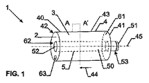
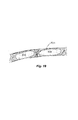
本開示の第1の態様に係る受容体1の第1の実施形態が図1に示され、この実施形態では、受容体1がバイオリアクタで使用されるのに適している。細胞培養のための受容体1は内部空間2を有し、この内部空間2は、図示のように環状であってもよいが、本明細書中で言及されるような他の形態を成してもよい。空間2は充填物3を収容する。受容体が細胞培養のために使用されるようになっている場合には、充填物3が細胞増殖に適合しなければならない。
A first embodiment of a receptor 1 according to the first aspect of the present disclosure is shown in FIG. 1, in which the receptor 1 is suitable for use in a bioreactor. The receptor 1 for cell culture has an
図示の環状形態において、内部空間2は、以下によって画定される環状容積を有する。
− 第1の外端41および第2の外端42と、矢印44によって示される長手方向に延びる長手方向壁43とを有する外側管状壁4。外側管状壁4は、長手方向44で環状容積の外側境界を画定する;
− 外側管状壁4の第1の外端41および第2の外端42のそれぞれで環状容積を画定して閉じる第1および第2の閉鎖体(61,62);
− 外側管状壁の第1の外端の方へ向けられた第1の外端51と、外側管状壁4の第2の外端の方へ向けられた第2の外端52とを有する内側長尺壁5。内側長尺壁5は外側管状壁4内に配置される。内側長尺壁5は、長手方向44に延びるとともに、環状容積の内側境界を画定し、該内側境界は外側境界によって包囲される。
In the annular form shown, the
An outer tubular wall 4 having a first
-First and second closures (61, 62) defining and closing an annular volume at each of the first
An inner side having a first
内側長尺壁5の第2の外端52は、第2の閉鎖体62と一致する。一例として、外側管状壁は、円筒状の外側管状要素40によって与えられる。内側長尺壁5は、円柱ロッドなどの中実の内側円柱要素50によって与えられてもよい。外側管状要素40は、円筒管状要素であり、長手方向と平行な中心軸線45を有する。内側円柱要素50および外側管状要素40は同軸状に装着されてもよい。
The second
内側円柱要素50の第1の外端は、内側円柱要素50を、ならびに、内側円柱要素50および外側管状要素40に固定されている閉鎖体61,62を用いて同様に外側管状要素40も、駆動機構、例えばバイオリアクタのモータに対して結合するために、結合要素53を備えてもよい。内部空間2へおよび/または内部空間2から媒体および/またはガスを与えるおよび/または引き出すために、第2の閉鎖体62には、受容体を媒体源またはガス源に結合するのに適したコネクタが設けられる。このコネクタ、または代わりに更なるコネクタは、第1の閉鎖体61または第2の閉鎖体62に設けられてもよい。
The first outer end of the inner
内部空間2は少なくとも部分的に充填物3で満たされる。一例として、充填物は、細胞増殖に適合する、鉱物キャリア、例えば、ケイ酸塩、リン酸カルシウム、有機化合物、例えば多孔質カーボン、天然物、例えばキトサン、高分子、または、バイオポリマーであってもよい。充填物は、規則正しい、または不規則な構造を有するビーズの形態を有することができ、あるいは、細胞増殖に適合する高分子の織りもしくは不織りのマイクロファイバまたは任意の他の材料を備えてもよい。また、充填物は、孔および/またはチャネルを伴う単体として設けることもできる。
The
随意的に、充填物は、50%〜98%の範囲内の多孔率Pを有してもよい。多孔率Pという用語は、所定の体積の材料中に存在する空気の体積であり、所定の体積の材料のパーセンテージとして表わされる。多孔率は、以下の式を用いて多孔質材料の単位体積当たりの重量Wxを測定することによって測定され得る。
P=100−(1−Wx/Wspec)
ここで、Wspecは、材料の比重量である。多孔質材料は、多孔質材料の1つの固体単位であってもよく、あるいは、複数の個々の単位、例えば、粒子、チップ、ビーズ、繊維、または、繊維塊であってもよい。
Optionally, the filling may have a porosity P in the range of 50% to 98%. The term porosity P is the volume of air present in a given volume of material and is expressed as a percentage of the given volume of material. The porosity can be measured by measuring the weight Wx per unit volume of the porous material using the following formula:
P = 100- (1-Wx / Wspec)
Here, Wspec is the specific weight of the material. The porous material may be a single solid unit of the porous material or may be a plurality of individual units such as particles, chips, beads, fibers, or fiber masses.
受容体の動作時、充填物、特に多孔質材料は、受容体に対して所定の相対位置に静止してもよく、あるいは、受容体内で受容体に対して、または場合によっては受容体の区画室内で移動してもよい。 During operation of the receptor, the filler, particularly the porous material, may rest at a predetermined relative position with respect to the receptor, or within the receptor relative to the receptor, or in some cases a compartment of the receptor. You may move indoors.
受容体は、随意的には0.1〜25回転/分の回転速度でその軸線45の周りで回転されるようになっている。
The receptor is optionally rotated about its
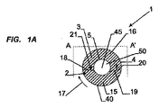
図1aの径方向断面において最も良く見えるように、内部空間は、細胞培養媒体15などの培養媒体で部分的に満たされる。一例として、液面18が少なくとも内側長尺壁5と接触する、あるいは、図1の実施形態に示されるように、内側長尺壁5が媒体15中に部分的に浸漬される。液面18の下側に配置される充填物3の部分は、細胞培養媒体などの培養媒体によって湿潤される。液面18よりも上側に配置される充填物3は、内部空間2内に存在するガスまたは空気と接触している。受容体が軸線45の周りで一方向に回転されると、例えば矢印17により示されるように時計回りに回転されると、細胞培養媒体15などの培養媒体は、充填物3に対して反対方向、例えば(19によって示される)反時計回り方向に回転する。細胞培養媒体15などの培養媒体は、栓流にしたがって充填物3の全体にわたって通される。受容体の例えば時計回りの回転時、細胞培養媒体などの培養媒体は、栓流の前縁20にあるガスまたは空気16を反時計回りに移動させる。媒体15の後縁21には、随意的に限られた陥凹部が形成され、それにより、ガスまたは空気16が後縁へ向けて吸引される。したがって、媒体15およびガスまたは空気16が充填物3全体にわたって通過する。
As best seen in the radial cross section of FIG. 1 a, the interior space is partially filled with a culture medium such as the cell culture medium 15. As an example, the
図2に示される代案として、代わりの受容体200の内側長尺壁5は、円筒管状要素250によって与えられてもよい。同じ参照符号は、図1の受容体1に関して開示されるものと同様の特徴を示す。
As an alternative shown in FIG. 2, the inner
外側管状壁4は、外側管状要素240によって与えられる。内側長尺壁5は、長尺な円筒管状要素250によって与えられる。外側管状要素240および長尺な円筒管状要素250は、2つの取り外し可能な閉鎖体261,262に固定される。第1の閉鎖体261には、長手方向44の軸線に沿って受容体を回転させるための駆動手段に対して受容体を結合するための結合要素253が設けられる。第1の閉鎖体261は、内部空間2を可撓性チューブなどの管路に接続するためのコネクタ263を更に備える。
The outer tubular wall 4 is provided by an outer
一例として、外側管状要素は、例えば110mmの長さLと例えば135mmの内径Doとを有するガラスチューブであってもよい。内側長尺要素は、例えば88.9mmの外径Diを有するフッ化ビニリデン樹脂(PVDF)であってもよい。内側長尺要素の外端、したがって内側長尺壁の外端は、閉鎖体261,262と一致する。閉鎖体は、シリコーンを使用して内側要素および外側要素に取り付けられてもよいステンレス鋼またはPVDFの環状ディスクであってもよい。コネクタ263を備えてもよい第1の閉鎖体261は、例えば約35mmの外径Dceを有する結合要素253を有する。
As an example, the outer tubular element may be a glass tube having a length L of, for example, 110 mm and an inner diameter Do of, for example, 135 mm. The inner elongate element may be, for example, vinylidene fluoride resin (PVDF) having an outer diameter Di of 88.9 mm. The outer end of the inner elongate element, and thus the outer end of the inner elongate wall, coincides with the closures 261,262. The closure may be an annular disc of stainless steel or PVDF that may be attached to the inner and outer elements using silicone. The first closure 261, which may include a
内部空間2は少なくとも部分的に充填物3で満たされる。一例として、充填物は、図1の実施形態における充填物と同一または同様であってもよい。
The
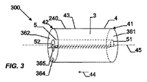
他の別の受容体300が図3に示される。同じ参照符号は、図1の受容体1に関して開示されるものと同様の特徴を示す。
Another
受容体は、内部空間を2つの区画室81,82に分ける2つの流体透過仕切り71,72を更に備える。流体透過仕切り71,72は、内側長尺壁5から外側管状壁4まで延びるとともに、環状軸線45の方向と平行な長手方向44で第1の閉鎖体361から第2の閉鎖体362まで延びる。一方の区画室81には充填物3が設けられる。一方の区画室82には充填物が設けられない。流体透過仕切りには、例えば多孔質仕切りを形成するために多孔質材料を使用することによって孔が設けられてもよく、あるいは、開口が設けられ、それにより、いずれにせよ、液体、すなわち、培養媒体、および、ガスを通過させることができる。しかしながら、仕切り71,72には、充填物が仕切りの一方側から他方側へ通過することを防止するのに十分小さい孔または開口が設けられる。
The receptor further comprises two fluid
外側管状壁4は、長手方向に対して垂直な平面に沿う径方向断面を有する外側管状要素240によって与えられ、その断面は円の形状を有する。
The outer tubular wall 4 is provided by an outer
内側長尺壁5は、長手方向に対して垂直な平面に沿う径方向断面を有する内側長尺要素350によって与えられ、その断面は切頂円または円弧の形状を有する。1つの実施形態では、円弧が円弧351と弦352とを有する。例えば、円弧の高さは、200mm(Dcc)、400mm(Do)、240mm(Di)、および、125mm(L)の寸法を有する。仕切り71,72は、この実施形態では、円弧の弦352と同一平面上にある。
The inner
2つの閉鎖体361,362のうちの第2の閉鎖体362には2つのコネクタ364,365が設けられる。第1のコネクタ364は外側管状壁4の近傍に設けられる。第2のコネクタ365は内側長尺壁5の近傍に設けられる。図3に示されるように、受容体が液体表面1001を有する培養媒体1000で部分的にのみ満たされると、受容体は、液体が内側長尺壁5と接触せずに内側長尺壁5から所定の距離にとどまるような位置へ回転されてもよい。受容体がこの位置に至らされると、媒体を除去する、または充填物3で満たされない区画室82へ媒体を供給するために第1のコネクタが使用されてもよい。コネクタ365を用いて媒体液面よりも上側でガスが除去され、または供給されてもよい。受容体の例えば最大で360°以上の角度にわたる時計回り、または反時計回りの回転によって、媒体は、2つの仕切りのうちの一方、特に媒体中に徐々に浸漬される仕切りを通過する。媒体は、充填物を通じてゆっくりと流れる。これは、回転に起因して充填物が徐々に媒体を通過するからである。受容体の回転に起因して、媒体は、栓流にしたがって充填物全体を通過して流れる。環状容積の全体にわたって媒体と充填物との間の均一な接触が起こる。充填物の一部が媒体を通過した時点で、媒体が徐々に充填物から浸出し、そのため、受容体内のガスが再び充填物と接触し、それにより、細胞が充填物の全体にわたって一様に増殖することができる。
Two
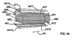
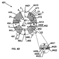
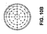
図4aおよび図4bを参照すると、更なる他の別の受容体400が示される。複数の環状セクション21,22,23,24、この特定の場合には4つの環状四分円によって内部空間2の環状容積が形成される。セクション21,22,23,24のそれぞれは、外側管状壁セクション441,442,443,444のそれぞれによって外側管状壁4の1つの部分を与える。セクションのそれぞれは、内側長尺壁セクション451,452,453,454のそれぞれによって内側長尺壁5の1つの部分を与える。
Referring to FIGS. 4a and 4b, yet another
セクションのそれぞれは、2つの径方向に延びるセクション壁を有する。一例として、セクション21は、2つの径方向に延びるセクション壁4411,4412を有する。これらのセクション壁は、液体およびガスを透過させない。セクション壁のそれぞれには、隣り合うセクションが互いに結合できるようにする装着手段4413,4414が設けられる。
Each of the sections has two radially extending section walls. As an example, the
環状セクションの容積を画定して閉じる第1および第2のセクション閉鎖体461,462が外側管状壁の第1および第2の外端にそれぞれある。セクション閉鎖体は、共に、受容体の環状容積2の第1および第2の閉鎖体のそれぞれを形成する。
First and
図4aおよび図4bを更に参照すれば分かるように、セクションのそれぞれには、各環状セクションの内部空間を3つの区画室481,482,483に分ける2つの流体透過仕切り471,472が更に設けられてもよい。流体透過仕切り471,472、例えば多孔質仕切りは、内側長尺壁5から外側管状壁4まで延びるとともに、管状軸線405の方向と平行な長手方向44で第1の閉鎖体461から第2の閉鎖体462まで延びる。1つの区画室482には充填物3が設けられる。2つの区画室481,483には充填物が設けられない。仕切りは、図3の受容体の仕切りと同様または同一であってもよい。
As can be further seen with reference to FIGS. 4a and 4b, each of the sections is further provided with two fluid permeable partitions 471,472 that divide the interior space of each annular section into three compartments 481,482,483. May be. The fluid
図3に示される場合と同様に、それぞれの環状セクション21,22,23,24ごとに、第1のコネクタ464が外側管状壁4の近傍に設けられる。第2のコネクタ465が内側長尺壁5の近傍に設けられる。図4から明らかなように、セクションのそれぞれは、受容体が軸線405の周りで回転されるときに、受容体400の独立した受容体セクションとして機能してもよい。各セクション内の充填物には、セクションの径方向位置に応じてこのセクション内に存在する媒体が供給される。
As in the case shown in FIG. 3, a
セクション、この実施形態では4つのセクション21,22,23,24を装着することにより、外側管状壁と内側長尺壁とを有する受容体が得られ、受容体の環状容積は、2つの閉鎖体によって外側管状壁の2つの外端で閉じられる。セクションの結合は、2つの径方向に延びるセクション壁を装着して結合することによって行なわれるため、2つの隣り合うセクションの組み合わせは、内側長尺壁5から外側管状壁4まで延びるとともに管状軸線405の方向と平行な長手方向44で第1の閉鎖体から第2の閉鎖体まで延びる液体およびガスを透過させない仕切りを形成する。この実施形態は、セクションのそれぞれに異なる細胞培養のための異なる媒体を設けることができるという利点を有する。また、セクションのうちの1つで充填物の反応が誤って機能する場合には、1つのセクションだけを置き換えることができる。
By mounting the section, in this embodiment four
この実施形態に示されるように、受容体(または、本明細書中に開示される任意の他の受容体)の回転が回転子によって与えられてもよい。1つの例において、この回転子は、外側管状壁の外面と少なくとも2つの支持ホイール490,491とを接触させることを含んでもよく、支持ホイールのうちの少なくとも1つが駆動される。
As shown in this embodiment, rotation of the receptor (or any other receptor disclosed herein) may be provided by a rotor. In one example, the rotor may include contacting the outer surface of the outer tubular wall and at least two
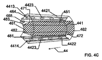
図4cおよび図4dは受容体401の別の実施形態を示す。図4cにおいて、同一の参照符号は、図4aの場合と同一の部分および要素を示す。この実施形態において、受容体401のセクションのそれぞれは、2つの径方向に延びるセクション壁4421,4422を有する。これらのセクション壁4421,4422は液体およびガスを透過する。各セクション壁4421はいくつかの開口4423を備え、これらの開口のそれぞれは、隣り合う区画室の第2のセクション壁4422における対応する開口を見出す。詳細Bに示されるように、第1のセクション壁4421の開口には、第2のセクション壁4422の対応する開口を通じて延びる外方延出リム4425が設けられてもよい。随意的に、接触する壁間で媒体が漏れるのを防止するために、隣り合うセクション壁の開口の周囲にシール4426が設けられる。別の実施形態では、シールの代わりに、受容体間に可撓性チューブが配置される。
4c and 4d show another embodiment of the
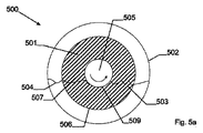
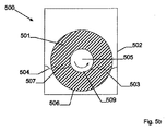
バイオリアクタ500の一実施形態が図5aおよび図5bに示される。図1に開示される受容体1と同様の少なくとも1つの受容体501が容器502内に回転可能に装着され、容器502は、図5aに示されるような例えば円形、あるいは、図5bに示されるような長方形(随意的には正方形)等の多角形など、任意の適した径方向断面を有してもよい。容器は部分的に培養媒体503で満たされ、そのため、液面504は、随意的に、バイオリアクタの軸線505よりも高く上昇しないが、少なくとも内側長尺壁509と接触する。受容体501は、受容体501の長手方向軸線と同一であるこの軸線505の周りで回転される。受容体501の長手方向軸線は、外側管状壁506の長手方向と平行な軸線である。随意的に、外側管状壁506には開口が設けられ、あるいは、外側管状壁506が、多孔質材料、例えば液体およびガスを透過する材料から形成される。そのような流体透過外側管状壁506が部分的に媒体503で満たされた容器502内で回転され、それにより、外側管状壁506の一部だけが媒体中に浸漬されると、外側管状壁506を通じて環状容積508内へ流れる媒体を充填物507に供給することができる。媒体の一部は、受容体が容器内で回転するようになっているときに充填物と共に引きずられてもよい。当業者であれば分かるように、受容体1,200,300または400に関連して記載される他の特徴が受容体501に加えられてもよい。
One embodiment of a
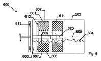
他のバイオリアクタ600が図6および図6Aに示される。図1に開示される受容体と同様の少なくとも1つの受容体601、この図では2つの受容体601,611が、容器602内に回転可能に装着される。容器は部分的に培養媒体603で満たされ、そのため、液面604は、随意的に、バイオリアクタの軸線605よりも高く上昇しないが、少なくとも内側長尺壁609と接触する。受容体601は、受容体601の長手方向軸線と同一であるこの軸線605の周りで回転される。受容体の長手方向軸線は、外側管状壁の長手方向と平行な軸線である。随意的に、外側管状壁606には開口が設けられ、あるいは、外側管状壁606が、多孔質材料、例えば液体およびガスを透過する材料から形成される。そのような流体透過外側管状壁606が部分的に媒体603で満たされた容器602内で回転され、それにより、外側管状壁606の一部だけが培養媒体603中に浸漬されると、外側管状壁606を通じて環状容積608内へ流れる培養媒体603を充填物607に供給することができる。培養媒体603の一部は、受容体が容器内で回転するようになっているときに充填物と共に引きずられてもよい。
Another
受容体のうちの少なくとも1つ、この実施形態では受容体601は、磁気要素612を備える。バイオリアクタは、受容体の磁気要素612と協働する磁気要素613を更に備える。両方の磁気要素613,612は、回転軸線605の周りでのバイオリアクタ600の磁気要素613の回転が受容体601の磁気要素612の回転を引き起こし、したがって、受容体601全体を回転させるように配置される。隣り合う受容体は共通シャフト620上に装着されてもよく、共通シャフトの周りでこれらの受容体が回転する。隣り合う受容体601,611は所定位置で互いに結合されてもよく、そのため、受容体601の回転が受容体611の回転も同様に引き起こす。
At least one of the receptors, in this embodiment the
当業者であれば分かるように、液体およびガスを透過させない外側管状壁を有するが随意的に可撓性チューブによって受容体をガス貯留部または媒体貯留部に接続するためのコネクタを有する受容体は、図5および図6に関連して記載される方法と同様の方法で装着されて回転されてもよい。当業者であれば分かるように、受容体1,200,300または400に関連して記載される他の特徴が受容体601に加えられてもよい。
As will be appreciated by those skilled in the art, a receptor having an outer tubular wall that is impermeable to liquids and gases but optionally having a connector for connecting the receptor to a gas reservoir or media reservoir by a flexible tube is provided. , And may be mounted and rotated in a manner similar to that described in connection with FIGS. As will be appreciated by those skilled in the art, other features described in connection with receptor 1,200, 300 or 400 may be added to
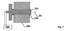
図7に示されるように、図3の受容体300などの受容体は、バイオリアクタをもたらすために駆動システムによって回転されてもよい。受容体は、受容体300の軸線45と一致する回転軸線の周りで回転できる回転可能シャフト701に装着される。シャフト701は、異形であり、内側長尺要素350の内部空隙702内に固有の回転位置で嵌合する。したがって、シャフト701の回転位置を制御することにより、軸線45周りの受容体の位置が明確に規定される。駆動システムは、シャフト701の回転を正確に制御するために、リニアモータなどのモータ703または任意の他の適した手段を更に備えてもよい。受容体がシャフト701上にわたって長手方向に移動することを防止するためのクランプ704、ねじ、または、任意の適した手段が、シャフト701上の受容体300の位置を長手方向705で固定してもよい。
As shown in FIG. 7, a receptor such as the
随意的に、複数の受容体300が共通シャフト701に装着されてもよいことが理解される。
It will be appreciated that optionally a plurality of
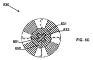
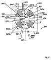
図8a〜図8cは、協働する駆動シャフト801に装着される受容体の別の例の断面を示す。内側長尺要素850の内部空隙802およびシャフト801の外周の形状は、シャフトおよび受容体を限定された方法で、または更には固有の方法で装着できるように選択される。
Figures 8a-8c show a cross section of another example of a receiver mounted on a cooperating
図1の受容体と同様の受容体810において、内側長尺要素は、内側長尺要素の内壁に長手方向凹部811を有する。シャフト801上の隆起部812がこの凹部811内に嵌合する。受容体は、一義的な方法でシャフト上に嵌合する。隆起部812は凹部811内でスライド移動できてもよい。
In a
受容体820は、図1の受容体と同様の受容体である。内側長尺要素は、該内側長尺要素の内壁に2つの長手方向凹部821を有する。シャフト801上の2つの互いに垂直な隆起部822がこれらの凹部821内に嵌合する。受容体820は2つの方法でシャフト上に嵌合し、第1の位置が第2の位置に対して軸線周りで180°回転される。隆起部822は凹部821内でスライド移動できてもよい。
The
受容体830は、図4aおよび図4cの受容体と同様の受容体である。内側長尺要素は、区画室によって与えられる内側長尺要素の内壁のそれぞれに1つずつ、4つの長手方向凹部831を有する。シャフトは、該シャフト801上に4つの互いに垂直な隆起部832を備える略十字形状の断面を有する。隆起部のそれぞれは、区画室のうちの1つの凹部831内に嵌合する。受容体830は、4つの方法でシャフト上に嵌合する。隆起部832は凹部831内でスライド移動できてもよい。
当業者であれば分かるように、図1〜図6に関連して説明された受容体の他の特徴は、図7および図8を用いて開示された駆動システムと組み合わされてもよい。 As will be appreciated by those skilled in the art, other features of the receiver described in connection with FIGS. 1-6 may be combined with the drive system disclosed using FIGS.
図9を参照すると、本開示に係る更なる他の別の受容体901がバイオリアクタ900の一部であるとして示される。同じ参照符号は、図1の受容体1に関して開示される特徴と同様の特徴を示す。
Referring to FIG. 9, yet another
内部空間2の容積は、複数のセグメント921,922,923,924、この特定の場合には4つの四分円によって与えられる。
The volume of the
セクションのそれぞれは、外側管状壁部分9441,9442,9443,9444のそれぞれによって外側管状壁4の1つの部分を与える。セグメントのそれぞれは、内側長尺壁部分9451,9452,9453,9454のそれぞれによって内側長尺壁5の1つの部分を与える。
Each of the sections provides one portion of the outer tubular wall 4 by each of the outer
セグメントのそれぞれは2つの径方向に延びるセグメント壁を有する。一例として、セグメント921は2つの径方向に延びるセグメント壁9411,9412を有する。これらのセグメント壁は、液体およびガスを透過させない。
Each of the segments has two radially extending segment walls. As an example, the segment 921 has two radially extending
第1および第2の閉鎖体が、外側管状壁の第1および第2の外端のそれぞれでセグメントの容積2を画定して閉じ、したがって、受容体の容積2を閉じる。
First and second closures define and close the
セグメントのそれぞれには、各セグメントの内部空間を3つの区画室981,982,983に分ける2つの流体透過仕切り971,972が更に設けられてもよい。流体透過仕切り971,972は、内側長尺壁5から外側管状壁4まで延びるとともに、管状軸線905の方向と平行な長手方向944で第1の閉鎖体から第2の閉鎖体まで延びる。1つの区画室982には充填物3が設けられる。2つの区画室981,983には充填物が設けられない。仕切りは、図3の受容体の仕切りと同様または同一であってもよい。
Each of the segments may further include two fluid permeable partitions 971 and 972 that divide the internal space of each segment into three
受容体901は容器900内に回転可能に装着される。容器は部分的に培養媒体903で満たされ、そのため、液面904は、随意的に、バイオリアクタ900の軸線905よりも高く上昇しない。受容体901は、受容体901の長手方向軸線と同一であるこの軸線905の周りで回転される。受容体の長手方向軸線は、外側管状壁の長手方向と平行な軸線である。
The
区画室981,983のそれぞれには、内壁9451,9452,9453,9454のそれぞれに沿って長手方向スリットなどの適切な開口が設けられる。各外側管状壁部分9441,9442,9443,9444のそれぞれには開口が設けられ、あるいは、各外側管状壁部分が、多孔質材料、例えば液体およびガスを透過する材料から形成される。そのような流体透過外側管状壁が部分的に培養媒体903で満たされた容器900内で回転され、それにより、外側管状壁の一部だけが培養媒体903中に浸漬されると、外側管状壁を通じて容積内へ流れる培養媒体903を区画室内の充填物3に供給することができる。培養媒体903の一部は、受容体が容器内で回転するようになっているときに充填物と共に引きずられてもよい。培養媒体903は、内側長尺壁の内部空隙9450を更に満たしてもよい。開口991を通じて、培養媒体903は、セクション981,982に流入し、または該セクションから流出することができ、随意的には隣接するセクション982,981のそれぞれへ流れることができる。
Each of the
図10および図10a〜10cは、長手方向壁を形成する本体1002を含むとともにキャップ1004,1006の形態を成して終わる受容体1000の更なる例を示す。キャップ1004,1006は、図示のように取り外しできてもよく、また、接続された位置で、任意の流体を本体1002内に収容するために流体密なシールを形成してもよい。各キャップ1004,1006は、培養媒体を受けるための入口または出口を形成する開口1004a,1006aを含んでもよい(図11参照)が、入口および出口をそれぞれ同じキャップに同様に、または本体1002の長手方向壁に設けることができる。
FIGS. 10 and 10a-10c show a further example of a
少なくとも1つ、図示の場合には一対の流体透過構造体、例えば有孔隔壁1008,1010が、任意の充填物を収容するための区画室1012を形成するように設けられる(図12参照)。各隔壁1008または1010における穿孔は、区画室1012内の流体の流れおよび滞留時間を制御するべき形状およびサイズで設けられてもよく、また、隔壁間で同じであってもよく、または異なってもよい。
At least one, in the illustrated case, a pair of fluid permeable structures, such as
充填物は、前述した任意の構造を備えてもよいが、1つの実施形態では、繊維(織り、または不織りのポリエステル系繊維など)、特に不織PET繊維を備えてもよい。充填物は、それが受容体1000の区画室を完全に占め、したがって、本体1002の壁の内面および流体透過構造体(例えば隔壁1008,1010)と周方向で接触するような仕方で設けられてもよい。
The filler may comprise any of the structures described above, but in one embodiment may comprise fibers (such as woven or non-woven polyester fibers), particularly non-woven PET fibers. The filling is provided in such a way that it completely occupies the compartment of the
図11は、受容体1000が回転デバイス1100と関連付けられてもよいことを示す。デバイス1100は、受容体1000を受けて支持するとともに本体の長手方向軸線の周りで回転させるための一対のローラ1102を含んでもよい。この場合の受容体1000には、任意の流体(例えば、培養媒体、または、任意の濯ぎ物質あるいは回収物質)を区画室内に存在する任意の充填物を通じて分配するのに役立つべくローラ1102と係合してローラ1102により回転されるようになっている略円筒状の本体1002が設けられてもよい。
FIG. 11 shows that the
流体を区画室へ供給するための入口1004aおよび出口1006aと関連して管状コネクタ1014,1016が設けられてもよい。これは、受容体1000が静止している間または受容体が回転している間に行なわれてもよい。後者の場合、コネクタ1014,1016は、例えばスナップ式係合によりもたらされる回転継手を使用することによって、またはベアリングを使用することによって相対回転を可能にする仕方で接続されてもよい。任意の漏れを防止して細胞培養にとって望ましい無菌状態を維持するのに役立つようにOリングなどのシールが使用されてもよい。
図10〜図12の受容体1000の1つの利点は、構成の簡略さである。例えば、図示の実施形態において、受容体1000は、センサ、プローブ、混合器などを含まない。そのような構造を含むことが望ましい場合には、これが可能であり、また、これは、図13に示されるように、受容体1000を閉ループでリザーバ1200と接続することによって達成されてもよい。リザーバ1200は、循環流体の1つ以上の特性を測定するための任意の数のセンサまたは同様のものを含んでもよく、また、洗浄および殺菌の必要性を避けるために使い捨て容器(可撓性バッグなど)を含んでもよい。流体をループを通じて循環させるために蠕動ポンプ1202などのポンプが設けられてもよい。
One advantage of the
ここで、図14〜図16を参照して、この開示の更なる態様について説明する。この実施形態において、受容体1300は、先に詳述した任意の内容にしたがって構成されてもよく(したがって、ローラボトルを形成する)、また、入口1302および出口1304を含んでもよい。入口および出口1302,1304のそれぞれは、受容体1300の回転を可能にする管路に対して流体伝送を妨げない仕方で管路を過度に締め付ける、またはねじることなく接続されてもよく、それにより、受容体が回転される間、受容体1300へのおよび受容体1300からの連続した流れを可能にしてもよい。具体的には、管路は、入口1302または出口1304のそれぞれに接続するための開放端を有するコイル状チューブ1306を備えてもよく、また、反対側の端部が任意の流体リザーバと関連してもよい。流体を管路および受容体1300を通じて移動させるために適したポンプ装置が設けられてもよい。
A further aspect of this disclosure will now be described with reference to FIGS. In this embodiment, the
図15および図16は、回転を可能にするようになっている管路を含む、図14の受容体の実施形態の1つの想定し得る使用の仕方を示す。具体的には、図15に示されるように、受容体1300は、適した回転子(ローラ1308など)を使用して、1つ以上の完全回転にわたって時計回りなどの第1の方向に回転されてもよい。管路を締め付けずに可能な回転数は異なり得るが、最低でも2〜3回転は可能なはずであると想定される。受容体1300は、その後、1つ以上の完全回転にわたって第2の反対の方向に回転されてもよい。より具体的には、回転は、コイル状チューブをその定位置に戻すために第1の方向における回転数にわたってもよく、更に、コイル状チューブが締まり付かない、またはさもなければ流体伝送を妨げない限りにわたって第2の方向で対応する回転数なされてもよい。回転および逆回転が連続的に、または断続的に行なわれてもよく、また、同じことが管路を介した流体の供給および回収にも当てはまる。
FIGS. 15 and 16 illustrate one possible use of the receiver embodiment of FIG. 14, including a conduit adapted to allow rotation. Specifically, as shown in FIG. 15, the
また、図14に戻って参照すると分かるように、受容体1300がセンサ1310を含む場合、受容体は、検出のために使用される任意のエネルギー源に接続されてもよい。そのような場合、ケーブル1312などの任意の伝送ラインが、ねじれ、または締め付けを伴うことなく先に考慮された仕方で相対回転を受け入れるべくコイル状または螺旋状であってもよい。この場合も先と同様に、任意のセンサまたは同様のものを任意の再循環ループ内に配置することが望ましい。これは、それにより、受容体1300のコストを下げるからである。
Also, as can be seen with reference back to FIG. 14, if the
図16および図17は、ローラボトルの形態を成す受容体1400のための提案された構成の他の詳細を示す。例えば、入口1402および出口1404が共通壁1400aに設けられてもよい。入口1402は、固定床内の流体透過内側円筒体1400b内に配置されるチューブと関連付けられてもよく、このチューブは、導入される流体(ガス、液体、または、これらの両方)が入口1402を通じて簡単にすぐさま抜け出ないようにするのに役立つ。
FIGS. 16 and 17 show other details of the proposed configuration for the
また、図17は、ロータメーターなどの注入器1420を再循環ループ内に配置することによってガスが液体中へ導入されてもよいことも示す。配置は、入口1402の直ぐ上流側であってもよい。図18に示されるように、液体流に関連するガス導入のこの仕方は、好適には、泡立ちの発生を減らして質量輸送速度を向上させるのに役立つ。これは、液体によって分離されるポケット内にガスが残存するからである(図19参照)。また、図18は、受容体1400との直接的な接続のための通気を避けるべく、出口1404と関連付けられる伝送ライン1422が、図示のようにフィルタ1426を介して通気されてもよいリザーバ1424に戻ることも示す。
FIG. 17 also shows that gas may be introduced into the liquid by placing an
言うまでもなく、他の要素が受容体およびバイオリアクタに加えられてもよい。一例として、内側長尺壁が長尺な管状の壁、随意的には円筒状の壁であってもよい。内側管状壁の内部空隙は、温度センサ、位置センサ(例えば、回転軸線に対する受容体の方向を規定するため)、光センサ(例えば、細胞培養媒体などの培養媒体の色に関するデータを発生させるため)、pHセンサ、酸素センサ(溶存酸素(DO)センサなど)、CO2センサ、アンモニアセンサ、または、細胞バイオマスセンサ(例えば、濁り濃度計)などの1つ以上のセンサを受け入れるために使用されてもよい。そのようなセンサは、付加的に、または随意的に、閉鎖体内または閉鎖体上に配置されてもよい。 Of course, other elements may be added to the receptor and bioreactor. As an example, the inner long wall may be a long tubular wall, optionally a cylindrical wall. The internal cavity of the inner tubular wall is a temperature sensor, a position sensor (eg to define the orientation of the receptor relative to the axis of rotation), a light sensor (eg to generate data relating to the color of a culture medium such as a cell culture medium) Also used to accept one or more sensors such as pH sensors, oxygen sensors (such as dissolved oxygen (DO) sensors), CO 2 sensors, ammonia sensors, or cell biomass sensors (eg, turbidity meter) Good. Such sensors may additionally or optionally be placed within or on the closure.
受容体は、新鮮な栄養媒体のかん流、連続付加、および、等しい量の使用済み媒体の引き出しに対応してもよく、それにより、生体内状況に可能な限り近く近似される細胞培養状態の実現を可能にする。かん流細胞培養と例えば酵素グルコースバイオセンサとの組み合わせは、細胞培養のグルコース消費量を連続的に監視できるようにする。 Receptors may support perfusion of fresh nutrient media, continuous addition, and withdrawal of equal amounts of spent media, so that cell culture conditions that are as close as possible to in vivo conditions. Enable realization. The combination of perfused cell culture with, for example, an enzyme glucose biosensor, allows continuous monitoring of cell culture glucose consumption.
また、受容体内の媒体および充填物を加熱する、またはそれらの温度を維持するため、加熱ブランケットなどの加熱要素が外壁および随意的には内壁に設けられてもよいことも理解される。 It is also understood that heating elements, such as heating blankets, may be provided on the outer wall and optionally the inner wall to heat or maintain the temperature of the media and filler in the receiver.
実施例
例1:充填材料への酸素輸送
外壁と、有孔内壁と、2つの閉鎖体とを有し、一方の閉鎖体がキャップ含むPVCの円筒状の受容体(長さ120mm、内径75mm、および、外径90mm)に不織PET繊維から構成される66gのキャリア(約500mlの充填床)が充填された。受容体は350mlの水で満たされた。受容体のキャップは、スポンジを伴うシリコンキャップ(Siliconsen 培養プラグ, Fisher Scientific Bioblock)によって閉じられた。受容体内へ配置される蛍光DOプローブ(ドイツのレーゲンスブルクにあるPresens)によって酸化吸収速度が測定された(測定は、プローブが液体中にあるときに行なわれた)。受容体のキャップが開放されて、酸素の完全な脱離(0%DO)まで窒素ガスが受容体へフラッシングされた。受容体がSiliconsen 培養プラグを用いて閉じられ、ボトルがローラステーション上に配置された。プラグのスポンジが空気の流入を可能にした。酸素吸収の速度の後、酸素濃度の増大対時間が測定された。異なる回転速度で実験が行なわれた。2.60rpm、5rpm、および、6.65rpmにおいて、液体中のDOが約6分、5分、および、4分(13h−1、16h−1、38h−1のK1・aに対応する)のそれぞれで0%から75%まで増大した。
Examples Example 1: Oxygen Transport to Filling Material A PVC cylindrical receptacle (120 mm long, 75 mm inner diameter, with outer wall, perforated inner wall and two closures, one closure containing the cap. And an outer diameter of 90 mm) was filled with 66 g of a carrier (about 500 ml packed bed) composed of non-woven PET fibers. The receptor was filled with 350 ml of water. The receptor cap was closed by a silicone cap with a sponge (Siliconsen culture plug, Fisher Scientific Bioblock). The rate of oxidative absorption was measured by a fluorescent DO probe (Presens, Regensburg, Germany) placed in the receptor (measurement was performed when the probe was in liquid). The receptor cap was opened and nitrogen gas was flushed into the receptor until complete desorption of oxygen (0% DO). The receptor was closed using a Siliconsen culture plug and the bottle was placed on a roller station. The plug sponge allowed air to enter. After the rate of oxygen absorption, the increase in oxygen concentration versus time was measured. Experiments were performed at different rotational speeds. 2.60 rpm, 5 rpm, and 6.65 rpm, DO in liquid is about 6 minutes, 5 minutes, and 4 minutes (corresponding to K 1 · a of 13h −1 , 16h −1 , 38h −1 ) Each increased from 0% to 75%.
例2:部分的に充填された受容体における小規模細胞増殖
(90°の角度を規定する)4つの仕切りによって画定される1350mlの内部空間容積を有する、ガラス外壁と、有孔ステンレス鋼内壁と、1つのガラス閉鎖体と、キャップを含む1つのステンレス鋼閉鎖体とを伴う円筒状の受容体(長さ120mm、内径70mm、および、外径130mm)が、不織PET繊維から構成される1.33gのキャリアで満たされる充填床の10mlのセクションを含んだ。受容体のキャップがSiliconsen 培養プラグによって閉じられた。受容体は、殺菌されて、250mlの培養媒体(1.8g/Lのグルコース、5%のウシ胎仔血清、および、1%の非必須アミノ酸を伴うMEM)で満たされるとともに、12.2×106MDBK細胞(Madin−Darby Bovine Kidney Cell)(すなわち、1.2×10⁶細胞/cm3の充填床)が接種された。受容体は、37℃の培養器内で、ローラ(6.5rpm)上に配置された。キャップを通じたガス供給は、7日の期間にわたって細胞を増殖させるのに十分であった。5日の培養後、細胞密度が18.2×106細胞/cm3に達し、媒体が交換された。7日後、細胞密度が46.0×106細胞/cm3に達した(すなわち、7日で38.4倍のバイオマス増大)。
Example 2: Small-scale cell growth in a partially filled receptor A glass outer wall with a 1350 ml internal space volume defined by four partitions (defining a 90 ° angle), and a perforated stainless steel inner wall A cylindrical receptor (length 120 mm, inner diameter 70 mm, and outer diameter 130 mm) with one glass closure and one stainless steel closure containing a cap is composed of non-woven PET fibers 1 It contained a 10 ml section of a packed bed filled with 33 g carrier. The receptor cap was closed by a Siliconcon culture plug. The receptor is sterilized and filled with 250 ml culture medium (1.8 g / L glucose, 5% fetal calf serum, and MEM with 1% non-essential amino acids) and 12.2 × 10. 6 MDBK cells (Madin-Darby Bovine Kidney Cell) (ie, a packed bed of 1.2 × 10 6 cells / cm 3 ) were inoculated. The receptor was placed on a roller (6.5 rpm) in a 37 ° C. incubator. The gas supply through the cap was sufficient to grow the cells over a period of 7 days. After 5 days of culture, the cell density reached 18.2 × 10 6 cells / cm 3 and the medium was changed. After 7 days, the cell density reached 46.0 × 10 6 cells / cm 3 (ie, 38.4-fold increase in biomass over 7 days).
本発明を具現化する受容体の目的を達成するための他の構成は当業者にとって自明である。言うまでもなく、本明細書中では、デバイスの様々な実施形態に関して、好ましい実施形態、特定の構成、および、形態、ならびに、材料について論じてきたが、添付の特許請求の範囲により規定されるこの発明の範囲から逸脱することなく、形態および細部において様々な変更または改良がなされてもよい。例えば、先に与えられた任意の処方は、使用されてもよい手順を単に代表しているにすぎない。機能性がブロック図に加えられ、またはブロック図から削除されてもよく、また、機能ブロック間で動作が置き換えられてもよい。本発明の範囲内で、記載された方法にステップが加えられ、または削除されてもよい。 Other arrangements for achieving the purpose of the receptor embodying the invention will be apparent to those skilled in the art. It will be appreciated that preferred embodiments, specific configurations and configurations, and materials have been discussed herein with respect to various embodiments of the device, but the invention as defined by the appended claims. Various changes or modifications in form and detail may be made without departing from the scope of the invention. For example, any prescription given above is merely representative of a procedure that may be used. Functionality may be added to or removed from the block diagram, and operations may be interchanged between functional blocks. Within the scope of the present invention, steps may be added or deleted to the described method.
Claims (96)
長手方向に延びる外側管状壁であり、該外側管状壁が径方向で前記内側区画室の外側境界を画定している、外側管状壁と、
前記外側管状壁の第1の外端および第2の外端のそれぞれで前記内側区画室を画定する第1の端部および第2の端部と、
前記内側区画室内にあり、繊維マトリクスを備える充填物と、
を備える受容体。 A receptor for cell culture having an inner compartment for cell proliferation,
An outer tubular wall extending longitudinally, wherein the outer tubular wall radially defines an outer boundary of the inner compartment;
A first end and a second end defining the inner compartment at each of a first outer end and a second outer end of the outer tubular wall;
A filler in the inner compartment and comprising a fiber matrix;
A receptor comprising:
長手方向に延びる外側管状壁と、前記外側管状壁の第1の外端および第2の外端のそれぞれで区画室を画定する第1の端部および第2の端部と、前記区画室内にあり、繊維マトリクスを備える充填物とを含むローラボトルと、
前記充填物を回転させるための回転子と、
を備える装置。 A device for growing cells,
A longitudinally extending outer tubular wall; a first end and a second end defining a compartment at each of a first outer end and a second outer end of the outer tubular wall; and in the compartment A roller bottle comprising a filler comprising a fiber matrix;
A rotor for rotating the filler;
A device comprising:
長手方向に延びる外側管状壁であり、該外側管状壁が長手方向で前記内側区画室の外側境界を画定している、外側管状壁と、
前記外側管状壁の第1の外端および第2の外端のそれぞれで前記内側区画室を画定する第1の端部および第2の端部と、
前記内側区画室内の充填物と、
前記内側区画室内に配置される少なくとも1つの流体透過隔壁と、
を備える受容体。 A receptor for cell culture having an inner compartment for cell proliferation,
An outer tubular wall extending longitudinally, the outer tubular wall defining an outer boundary of the inner compartment in the longitudinal direction;
A first end and a second end defining the inner compartment at each of a first outer end and a second outer end of the outer tubular wall;
A filling in the inner compartment;
At least one fluid permeable partition disposed within the inner compartment;
A receptor comprising:
繊維マトリクスを備える充填物をローラボトルに提供するステップと、
流体を前記ローラボトルに供給するステップと、
前記充填物を回転させるステップと、
を備える方法。 A method for culturing cells comprising:
Providing a roller bottle with a filling comprising a fiber matrix;
Supplying fluid to the roller bottle;
Rotating the filling;
A method comprising:
長手方向に延びる外側管状壁であり、該外側管状壁が長手方向で前記内側区画室の外側境界を画定している、外側管状壁と、
前記外側管状壁の第1の外端および第2の外端のそれぞれで前記内側区画室を画定する第1の端部および第2の端部と、
前記内側区画室内の充填物と、
前記内側区画室内で細胞を培養するために流体を送るための管路と、
を備える受容体。 A receptor for cell culture having an inner compartment for cell proliferation,
An outer tubular wall extending longitudinally, the outer tubular wall defining an outer boundary of the inner compartment in the longitudinal direction;
A first end and a second end defining the inner compartment at each of a first outer end and a second outer end of the outer tubular wall;
A filling in the inner compartment;
A conduit for sending fluid to cultivate cells in the inner compartment;
A receptor comprising:
(a)所定の充填物を含む収容器を第1の方向に回転させるステップと、
(b)前記第1の方向に回転させるステップの後、前記収容器を第2の方向に回転させるステップと、
を備える方法。 A method for culturing cells comprising:
(A) rotating a container containing a predetermined filler in a first direction;
(B) after the step of rotating in the first direction, the step of rotating the container in a second direction;
A method comprising:
第1の外端および第2の外端と長手方向に延びる長手方向壁とを有する外側管状壁であり、該外側管状壁が長手方向で前記環状容積部の外側境界を画定している、外側管状壁と、
前記外側管状壁の前記第1の外端および前記第2の外端のそれぞれで前記環状容積部を画定して閉じる第1の閉鎖体および第2の閉鎖体と、
前記外側管状壁の前記第1の外端の方へ向けられる第1の外端と、前記外側管状壁の前記第2の外端の方へ向けられる第2の外端とを有する内側長尺壁であり、該内側長尺壁が前記外側管状壁内に配置されており、前記内側長尺壁が、長手方向に延びるとともに、前記環状容積部の内側境界を画定しており、前記内側境界が前記外側境界によって包囲されている、内側長尺壁と、
によって画定されている、受容体。 A receptor for cell culture having an annular interior space containing a packing adapted for cell growth, the annular interior space having an annular volume, the annular volume being
An outer tubular wall having a first outer end and a second outer end and a longitudinally extending longitudinal wall, the outer tubular wall longitudinally defining an outer boundary of the annular volume A tubular wall;
A first closure and a second closure defining and closing the annular volume at each of the first outer end and the second outer end of the outer tubular wall;
An inner elongate having a first outer end directed toward the first outer end of the outer tubular wall and a second outer end directed toward the second outer end of the outer tubular wall. A wall, the inner elongated wall being disposed within the outer tubular wall, the inner elongated wall extending longitudinally and defining an inner boundary of the annular volume, the inner boundary An inner elongated wall surrounded by the outer boundary;
A receptor, defined by
前記第1の流体透過仕切りおよび前記第2の流体透過仕切りが、前記内側長尺壁から前記外側管状壁まで延びるとともに、管状軸線の方向と平行な長手方向で前記第1の閉鎖体から前記第2の閉鎖体まで延びており、
第1の区画室および第2の区画室のうちの一方が充填物を収容していない、
請求項49〜54のいずれか一項に記載の受容体。 The receiver further comprises at least a first fluid permeable partition and a second fluid permeable partition dividing the interior space into at least two compartments;
The first fluid permeable partition and the second fluid permeable partition extend from the inner elongated wall to the outer tubular wall and from the first closure body in a longitudinal direction parallel to the direction of the tubular axis. Extending to 2 closures,
One of the first compartment and the second compartment does not contain a filling,
55. The receptor according to any one of claims 49 to 54.
(a)請求項49〜81のいずれか一項に記載の受容体内へ、
細胞、および、
培養媒体、
を導入するステップと、
(b)前記外側管状壁の長手方向が略水平となる状態で前記受容体を配置するステップであり、前記外側管状壁がその長手方向と平行な軸線に沿って回転可能である、ステップと、
(c)前記受容体の前記外側管状壁を前記軸線に沿って回転させるステップと、
を備える方法。 A method for culturing cells comprising:
(A) into the receptor according to any one of claims 49 to 81;
Cells, and
Culture medium,
The steps of introducing
(B) placing the receptor in a state where the longitudinal direction of the outer tubular wall is substantially horizontal, the outer tubular wall being rotatable along an axis parallel to the longitudinal direction;
(C) rotating the outer tubular wall of the receptor along the axis;
A method comprising:
Applications Claiming Priority (3)
| Application Number | Priority Date | Filing Date | Title |
|---|---|---|---|
| US201261735841P | 2012-12-11 | 2012-12-11 | |
| US61/735,841 | 2012-12-11 | ||
| PCT/US2013/074307 WO2014093444A1 (en) | 2012-12-11 | 2013-12-11 | Recipient for cell cultivation |
Publications (2)
| Publication Number | Publication Date |
|---|---|
| JP2016504024A true JP2016504024A (en) | 2016-02-12 |
| JP2016504024A5 JP2016504024A5 (en) | 2016-11-10 |
Family
ID=50934912
Family Applications (2)
| Application Number | Title | Priority Date | Filing Date |
|---|---|---|---|
| JP2015545945A Pending JP2016501525A (en) | 2012-12-11 | 2013-12-11 | System and method for separation of cells in a fixed bed reactor |
| JP2015545946A Pending JP2016504024A (en) | 2012-12-11 | 2013-12-11 | Receptors for cell culture |
Family Applications Before (1)
| Application Number | Title | Priority Date | Filing Date |
|---|---|---|---|
| JP2015545945A Pending JP2016501525A (en) | 2012-12-11 | 2013-12-11 | System and method for separation of cells in a fixed bed reactor |
Country Status (6)
| Country | Link |
|---|---|
| US (2) | US10280391B2 (en) |
| EP (2) | EP2931870A4 (en) |
| JP (2) | JP2016501525A (en) |
| CN (3) | CN104903435A (en) |
| SG (2) | SG11201504219QA (en) |
| WO (2) | WO2014093444A1 (en) |
Families Citing this family (19)
| Publication number | Priority date | Publication date | Assignee | Title |
|---|---|---|---|---|
| US8506797B2 (en) * | 2011-04-10 | 2013-08-13 | Therapeutic Proteins International, LLC | Downstream bioprocessing device |
| CN112662611A (en) * | 2014-01-23 | 2021-04-16 | 日产化学工业株式会社 | Culture medium composition |
| JP6351113B2 (en) | 2015-01-29 | 2018-07-04 | 藤森工業株式会社 | Shaking culture apparatus and culture method using the same |
| WO2017019514A1 (en) * | 2015-07-24 | 2017-02-02 | Bioreactor Sciences Llc | Horizontally rocked bioreactor system |
| EP3394242A2 (en) * | 2015-12-22 | 2018-10-31 | Corning Incorporated | Cell separation device and method for using same |
| CN109689853B (en) | 2016-08-27 | 2022-08-23 | 三维生物科技有限公司 | Bioreactor |
| BE1024733B1 (en) | 2016-11-09 | 2018-06-14 | Univercells Sa | CELL GROWTH MATRIX |
| EP3492578B1 (en) * | 2016-12-27 | 2021-05-12 | Fullstem Co., Ltd. | Method for harvesting cultured cells from three-dimensional porous scaffold |
| US20210130760A1 (en) | 2017-12-20 | 2021-05-06 | Univercells Technologies S.A. | Bioreactor and related methods |
| IT201800004911A1 (en) * | 2018-04-27 | 2019-10-27 | EQUIPMENT FOR DYNAMIC FERMENTATION IN SOLID STATE | |
| JP6628448B2 (en) * | 2018-05-29 | 2020-01-08 | 藤森工業株式会社 | Shaking culture apparatus and culture method using the same |
| CN108913600B (en) * | 2018-08-16 | 2023-06-27 | 杭州德适生物科技有限公司 | Microscopic insemination operation dish |
| US11661576B2 (en) | 2019-02-05 | 2023-05-30 | Corning Incorporated | Packed-bed bioreactor systems and methods of using the same |
| US11118151B2 (en) | 2019-11-05 | 2021-09-14 | Corning Incorporated | Fixed bed bioreactor and methods of using the same |
| CN114761534A (en) * | 2019-11-27 | 2022-07-15 | 康宁股份有限公司 | Fixed bed cell culture and harvesting systems and methods of use thereof |
| US20220186168A1 (en) * | 2020-12-11 | 2022-06-16 | Cell Spinpod LLC | Rotating suspension culture devices that allow direct microscopy, in situ assays, and automation |
| BR112023025344A2 (en) * | 2021-06-03 | 2024-02-27 | Univercells Tech Sa | BIOREACTOR SYSTEM WITH ENHANCED CELL COLLECTION CAPACITIES AND RELATED METHODS |
| CN114456938A (en) * | 2022-03-02 | 2022-05-10 | 蓝莲(杭州)生物科技有限公司 | Rolling cell culture instrument |
| WO2023249816A1 (en) * | 2022-06-22 | 2023-12-28 | Corning Incorporated | Fixed bed cell culture reactor vessel for substrate alignment and sampling |
Citations (7)
| Publication number | Priority date | Publication date | Assignee | Title |
|---|---|---|---|---|
| JPH0463584A (en) * | 1990-06-29 | 1992-02-28 | Fuji Photo Film Co Ltd | Bioreactor equipment |
| US5432087A (en) * | 1990-11-29 | 1995-07-11 | Spielmann; Richard | Apparatus having rotatable planar trays for culturing microorganisms |
| JPH08173145A (en) * | 1994-09-12 | 1996-07-09 | Becton Dickinson & Co | Roller bottle for simultaneous cell culture through membraneand method for simultaneous cell culture using the same |
| JP2002306155A (en) * | 2001-03-27 | 2002-10-22 | Becton Dickinson & Co | Method for cell culture and apparatus therefor |
| JP2004041093A (en) * | 2002-07-12 | 2004-02-12 | Mitsubishi Heavy Ind Ltd | Apparatus and method for cell culture |
| US20110281343A1 (en) * | 2008-10-02 | 2011-11-17 | Gay Roger J | Bioreactor with rods arrayed for culturing anchorage-dependent cells |
| JP2012521210A (en) * | 2009-03-24 | 2012-09-13 | ジャン−パスカル ザンボ, | Disposable bioreactor and single use agitation system |
Family Cites Families (39)
| Publication number | Priority date | Publication date | Assignee | Title |
|---|---|---|---|---|
| US4322296A (en) * | 1980-08-12 | 1982-03-30 | Kansas State Univ. Research Foundation | Method for wastewater treatment in fluidized bed biological reactors |
| US5266476A (en) | 1985-06-18 | 1993-11-30 | Yeda Research & Development Co., Ltd. | Fibrous matrix for in vitro cell cultivation |
| US4720462A (en) | 1985-11-05 | 1988-01-19 | Robert Rosenson | Culture system for the culture of solid tissue masses and method of using the same |
| JPH02109973A (en) * | 1988-10-19 | 1990-04-23 | Shimadzu Corp | Cell culture device |
| JPH02177882A (en) * | 1988-12-29 | 1990-07-10 | Shimadzu Corp | Level sensor for cell-culturing device |
| FR2690926B1 (en) | 1992-05-06 | 1995-08-04 | Lvmh Rech | VARIABLE VOLUME REACTOR DEVICE AND CELL CULTURE METHOD. |
| US5958761A (en) * | 1994-01-12 | 1999-09-28 | Yeda Research And Developement Co. Ltd. | Bioreactor and system for improved productivity of photosynthetic algae |
| IL108321A (en) * | 1994-01-12 | 1998-10-30 | Yeda Res & Dev | Bioreactor and system for improved productivity of photosynthetic algae |
| JP3639007B2 (en) | 1995-08-22 | 2005-04-13 | 京都水研株式会社 | Stirred tank type bioreactor |
| GB9803362D0 (en) * | 1998-02-17 | 1998-04-15 | Cellon Sa | A cell culture vessel |
| JP2000125848A (en) * | 1998-10-19 | 2000-05-09 | Agriculture Forestry & Fisheries Technical Information Society | Tool for cell culture and simple cell culture by using the same tool |
| EP1253976A2 (en) | 2000-01-25 | 2002-11-06 | The Victoria University Of Manchester | Delayed release of fluids |
| US6720178B1 (en) * | 2000-06-29 | 2004-04-13 | University Of Louisville Research Foundation, Inc. | Self-feeding roller bottle |
| KR20020088848A (en) * | 2001-05-21 | 2002-11-29 | (주)코아바이오텍 | Cell Culture Tube and Multiple Roller Tube Cell Culture System Using The Same |
| US7993908B2 (en) * | 2001-07-17 | 2011-08-09 | Parsortix, Inc. | Microstructure for particle and cell separation, identification, sorting, and manipulation |
| TWI242600B (en) * | 2001-11-09 | 2005-11-01 | Ind Tech Res Inst | Collection, culture device and method for drawing out cell suspension from cell supply source |
| EP1548099A1 (en) * | 2002-07-31 | 2005-06-29 | Japan Science and Technology Agency | Automatic culture apparatus for cell or tisse with biological origin |
| JP4242618B2 (en) * | 2002-09-03 | 2009-03-25 | オリンパス株式会社 | Incubator |
| JP2004089136A (en) * | 2002-09-03 | 2004-03-25 | Olympus Corp | Culture vessel |
| CN1300297C (en) | 2002-09-20 | 2007-02-14 | 华东理工大学 | Digestive reactor for animal cell extension inoculation |
| US7390653B2 (en) * | 2002-12-04 | 2008-06-24 | Synthecon, Inc. | Culture chamber for biologicals |
| EP1596967A4 (en) | 2003-02-13 | 2006-06-14 | Ilc Dover Inc | Flexible disposable vessel |
| DE10322054B4 (en) * | 2003-05-15 | 2015-06-18 | Sartorius Stedim Biotech Gmbh | Apparatus and method for culturing cells |
| CN1878858B (en) * | 2003-11-10 | 2012-10-03 | 威尔森沃尔夫制造公司 | Compartmentalized device for cell culture, cell processing, and sample dialysis |
| KR100850733B1 (en) * | 2004-04-13 | 2008-08-06 | 도요 세이칸 가부시키가이샤 | Double incubator and incubating method |
| DE102004062828B4 (en) * | 2004-12-27 | 2007-01-11 | Fresenius Medical Care Deutschland Gmbh | Reactor with a rotatably arranged reactor unit |
| CN1740314A (en) * | 2005-07-21 | 2006-03-01 | 高春平 | Continuous filling automatic cell culture system |
| BE1016793A4 (en) * | 2005-10-04 | 2007-06-05 | Artelis | CELL CULTURE METHOD AND DEVICE FOR CARRYING OUT SAME |
| US7856704B2 (en) * | 2005-10-14 | 2010-12-28 | Gm Global Technology Operations, Inc. | Monitoring system for clinching process |
| JP2007222064A (en) * | 2006-02-23 | 2007-09-06 | Scimedia Ltd | Hollow fiber type culture apparatus |
| DE102006044795A1 (en) * | 2006-09-13 | 2008-03-27 | Schweigert, Florian, Prof. Dr.med.vet. | Determination of ingredients from biological materials |
| CN101668843A (en) | 2007-04-27 | 2010-03-10 | 东洋制罐株式会社 | Cell culture apparatus, cell culture system and cell culture method |
| WO2009139703A1 (en) | 2008-05-15 | 2009-11-19 | Ge Healthcare Bio-Sciences Ab | Method for cell expansion |
| DE102008039812A1 (en) * | 2008-08-25 | 2010-03-04 | Yvonne Ibold | Cell culture vessel with container, useful to extract cells, comprises inlet opening to absorb cell suspension in container, opening for applying pressure difference to suck liquid, and microcarrier comprising material to adhere cell |
| CN102108333B (en) * | 2009-12-29 | 2014-08-13 | 上海日泰医药设备工程有限公司 | Fluidized bed bioreactor |
| WO2011133437A2 (en) | 2010-04-19 | 2011-10-27 | Atmi Bvba | Drain connector for fluid processing and storage containers |
| US9115336B2 (en) * | 2010-05-25 | 2015-08-25 | Muffin Incorporated | Methods, substrates, and systems useful for cell seeding of medical grafts |
| EP2691177B1 (en) * | 2011-03-28 | 2018-07-25 | Corning Incorporated | Container cap with kink-resistant connector |
| CN103476924A (en) | 2011-04-15 | 2013-12-25 | 普拉里斯坦有限公司 | Methods and systems for harvesting cells |
-
2013
- 2013-12-11 US US14/648,590 patent/US10280391B2/en active Active
- 2013-12-11 EP EP13862027.3A patent/EP2931870A4/en active Pending
- 2013-12-11 CN CN201380064957.6A patent/CN104903435A/en active Pending
- 2013-12-11 SG SG11201504219QA patent/SG11201504219QA/en unknown
- 2013-12-11 CN CN201380064887.4A patent/CN105229139B/en active Active
- 2013-12-11 SG SG11201504217UA patent/SG11201504217UA/en unknown
- 2013-12-11 WO PCT/US2013/074307 patent/WO2014093444A1/en active Application Filing
- 2013-12-11 WO PCT/US2013/074298 patent/WO2014093439A1/en active Application Filing
- 2013-12-11 JP JP2015545945A patent/JP2016501525A/en active Pending
- 2013-12-11 CN CN202111185751.1A patent/CN114214192A/en active Pending
- 2013-12-11 JP JP2015545946A patent/JP2016504024A/en active Pending
- 2013-12-11 EP EP13862977.9A patent/EP2931871A4/en active Pending
- 2013-12-11 US US14/648,571 patent/US10781417B2/en active Active
Patent Citations (7)
| Publication number | Priority date | Publication date | Assignee | Title |
|---|---|---|---|---|
| JPH0463584A (en) * | 1990-06-29 | 1992-02-28 | Fuji Photo Film Co Ltd | Bioreactor equipment |
| US5432087A (en) * | 1990-11-29 | 1995-07-11 | Spielmann; Richard | Apparatus having rotatable planar trays for culturing microorganisms |
| JPH08173145A (en) * | 1994-09-12 | 1996-07-09 | Becton Dickinson & Co | Roller bottle for simultaneous cell culture through membraneand method for simultaneous cell culture using the same |
| JP2002306155A (en) * | 2001-03-27 | 2002-10-22 | Becton Dickinson & Co | Method for cell culture and apparatus therefor |
| JP2004041093A (en) * | 2002-07-12 | 2004-02-12 | Mitsubishi Heavy Ind Ltd | Apparatus and method for cell culture |
| US20110281343A1 (en) * | 2008-10-02 | 2011-11-17 | Gay Roger J | Bioreactor with rods arrayed for culturing anchorage-dependent cells |
| JP2012521210A (en) * | 2009-03-24 | 2012-09-13 | ジャン−パスカル ザンボ, | Disposable bioreactor and single use agitation system |
Also Published As
| Publication number | Publication date |
|---|---|
| EP2931870A1 (en) | 2015-10-21 |
| WO2014093444A1 (en) | 2014-06-19 |
| CN104903435A (en) | 2015-09-09 |
| CN105229139B (en) | 2018-02-13 |
| CN105229139A (en) | 2016-01-06 |
| CN114214192A (en) | 2022-03-22 |
| EP2931870A4 (en) | 2016-07-20 |
| SG11201504219QA (en) | 2015-06-29 |
| SG11201504217UA (en) | 2015-06-29 |
| JP2016501525A (en) | 2016-01-21 |
| US10781417B2 (en) | 2020-09-22 |
| EP2931871A4 (en) | 2016-07-20 |
| EP2931871A1 (en) | 2015-10-21 |
| US10280391B2 (en) | 2019-05-07 |
| US20150322399A1 (en) | 2015-11-12 |
| US20150299634A1 (en) | 2015-10-22 |
| WO2014093439A1 (en) | 2014-06-19 |
Similar Documents
| Publication | Publication Date | Title |
|---|---|---|
| JP2016504024A (en) | Receptors for cell culture | |
| ES2955959T3 (en) | A bioreactor system and method thereof | |
| US20220333059A1 (en) | Disposable bioprocess system supporting biological activity | |
| CN101985600B (en) | Turnover membrane bioreactor for use in micro-gravity environment | |
| US11015159B2 (en) | Single-use cell culturing apparatus and culturing bag | |
| JP2015531602A (en) | Disposable bottle in reactor tank | |
| JP6487917B2 (en) | Disposable bioreactor and methods for constructing and using disposable bioreactors | |
| TWI696698B (en) | Shake-type culture apparatus and culture method using the same | |
| CN102199537B (en) | Membrane bioreactor used in microgravity environment and simulated microgravity environment | |
| KR101103693B1 (en) | Cell Culture Tube of Syringe Shape and Multiple Cell Culture Device Using the same | |
| BRPI0803630B1 (en) | taylor vortex flow bioreactor for cell culture | |
| CN104704107A (en) | Cell culture method and system | |
| Pörtner et al. | Cultivation of mammalian cells in fixed-bed reactors | |
| CN210012862U (en) | Stem cell culture device | |
| RU2797021C1 (en) | Asymmetric conical bioreactor system and method for its use | |
| CN201971840U (en) | Peristaltic circulating bioreactor | |
| CN113717853A (en) | Cell culture apparatus and method | |
| CN102174394A (en) | Peristaltic circulating bioreactor and culture solution circulating method thereof | |
| BR102012028234B1 (en) | annular rotation bioreactor for cell culture |
Legal Events
| Date | Code | Title | Description |
|---|---|---|---|
| A521 | Request for written amendment filed |
Free format text: JAPANESE INTERMEDIATE CODE: A523 Effective date: 20160920 |
|
| A621 | Written request for application examination |
Free format text: JAPANESE INTERMEDIATE CODE: A621 Effective date: 20160920 |
|
| A131 | Notification of reasons for refusal |
Free format text: JAPANESE INTERMEDIATE CODE: A131 Effective date: 20170725 |
|
| A521 | Request for written amendment filed |
Free format text: JAPANESE INTERMEDIATE CODE: A523 Effective date: 20171025 |
|
| A131 | Notification of reasons for refusal |
Free format text: JAPANESE INTERMEDIATE CODE: A131 Effective date: 20180227 |
|
| A521 | Request for written amendment filed |
Free format text: JAPANESE INTERMEDIATE CODE: A523 Effective date: 20180528 |
|
| A02 | Decision of refusal |
Free format text: JAPANESE INTERMEDIATE CODE: A02 Effective date: 20181023 |