JP2016226236A - Non-contact power supply device and non-contact power reception device - Google Patents
Non-contact power supply device and non-contact power reception device Download PDFInfo
- Publication number
- JP2016226236A JP2016226236A JP2015113203A JP2015113203A JP2016226236A JP 2016226236 A JP2016226236 A JP 2016226236A JP 2015113203 A JP2015113203 A JP 2015113203A JP 2015113203 A JP2015113203 A JP 2015113203A JP 2016226236 A JP2016226236 A JP 2016226236A
- Authority
- JP
- Japan
- Prior art keywords
- coil
- detection
- power supply
- power
- electromotive
- Prior art date
- Legal status (The legal status is an assumption and is not a legal conclusion. Google has not performed a legal analysis and makes no representation as to the accuracy of the status listed.)
- Granted
Links
Images


Abstract
Description
本発明は、電磁結合によって無線給電を行う非接触給電システムに於いて使用される非接触給電装置及び非接触受電装置に関し、特に、非接触給電装置及び非接触受電装置間の互いの近接や位置ずれを検知することが可能な非接触給電装置及び非接触受電装置に関する。 The present invention relates to a non-contact power feeding device and a non-contact power receiving device used in a non-contact power feeding system that performs wireless power feeding by electromagnetic coupling, and in particular, proximity and position between the non-contact power feeding device and the non-contact power receiving device. The present invention relates to a non-contact power feeding device and a non-contact power receiving device capable of detecting a shift.
非接触給電システムにおける金属異物等の異物検出技術として、例えば、特許文献1,2に記載されたものが公知である。
As a foreign matter detection technique such as a metallic foreign matter in the non-contact power feeding system, for example, those described in
特許文献1に記載の無線電力伝送装置(非特許文献1の図3〜図8,請求項1,段落〔0046〕−〔0080〕参照)では、給電コイル(第1自己共振コイル)の両側に、該給電コイルと同方向に向けて異物検出用第1自己共振コイル及び異物検出用第2自己共振コイルを配設し、異物検出用第1自己共振コイルに対して、異物検出用第2自己共振コイルと共振する共振周波数の高周波エネルギーE1を供給すると共に、異物検出用第2自己共振コイルに誘導される交流電流のエネルギーE2を検出し、両者間のエネルギー伝送効率P1=E2/E1を求め、伝送効率P1が所定の閾値以下となった場合には、異物が存在すると判定することによって異物検出を行うものである。
In the wireless power transmission device described in Patent Document 1 (see FIGS. 3 to 8 of Non-Patent
特許文献2に記載の非接触電力伝送システム(特許文献2の段落〔0036〕−〔0037〕,図5,図6参照)では、給電コイル(一次コイル)と、該給電コイルを覆うカバーと、該カバー周辺に存在する物体を検出するセンサコイルとを備え、該センサコイルの巻き軸を、給電コイルの巻き軸に対して略直交するように配置した構成としたものである。センサコイルは、給電コイル及び給電コイルのコアを巻き込むようにして、給電コイルにより発生する磁束とセンサコイルにより発生する磁束とが直交するように配置される。この構成では、カバー上に異物が存在する場合、センサコイル周辺のインピーダンスが変化し、センサコイルの共振周波数がずれる。そこで、センサコイルの共振周波数のずれを検出することによって異物検出を行う。また、センサコイルの巻き軸が、給電コイルの巻き軸と略直交する構成としたことで、両コイル間の干渉を抑えて、異物検出の精度を向上させている。
In the non-contact power transmission system described in Patent Document 2 (see paragraphs [0036]-[0037] of
一方、非接触給電システムに於いて、非接触給電装置及び非接触受電装置の互いの接近や位置ずれを検知する技術としては、例えば、特許文献3,4に記載のものが公知である。
On the other hand, in the non-contact power supply system, for example, the techniques described in
特許文献3(特許文献3の請求項1,図1,図17,段落〔0039〕,〔0044〕−〔0046〕参照)には、給電コイル(1)と、受電コイル(7)と受電コンデンサ(8)とを含む受電共振回路を有するワイヤレス受電装置に非接触で電力供給を行うワイヤレス給電装置であって、給電コイル(1)と、受電共振回路の共振電流を検出する共振電流検出器(6)と、給電コイル(1)に交流電流を供給することによって、給電コイル(1)と受電コイル(7)との磁場共振現象に基づき、給電コイル(1)から受電コイル(7)に電力供給を行わせる制御回路であって、交流電流の周波数と共振電流検出器によって検出した共振電流の周波数とを関連付ける当該制御回路(111)とを備え、給電コイル(1)は、実質的に共振回路を構成せず、共振電流検出器(6)は、検出コイル(6a)と検出コンデンサ(6c)とを含む検出共振回路を有し、検出コイル(6a)と受電コイル(7)との磁場共振現象に基づき、受電共振回路の共振電流を検出し、検出コイル(6a)の巻回領域は、給電コイル(1)の巻回領域より小さく、検出コイル(6a)は、巻回中心軸が給電コイル(1)によって生じる磁場ベクトルに対して80°以上100°以下の角度をなすように配置されたワイヤレス給電装置が記載されている。給電コイル(1)に受電コイル(7)が接近すると、受電コイル(7)に共振電流が誘導される。このとき、共振電流によって検出コイル(6a)と検出コンデンサ(6c)とを含む検出共振回路が共振し、この検出共振回路に誘導される共振電流を検出することによって、ワイヤレス給電装置の側で受電コイル(7)の接近を検出することが可能となる。
Patent Document 3 (see
特許文献4(特許文献4の図1−3,段落〔0040〕−〔0049〕参照)には、移動体に設置され受電コイル(103)を有する受電装置(20)と、受電コイル(103)に対し非接触で電力を供給する送電コイル(102)を有する送電装置(10)と、送電コイル(102)の近辺に配置され、それぞれのループ軸が互いに直交する複数のループアンテナ素子を有する第1のアンテナ(301)と、受電コイル(102)の近辺に配置され、受電コイル(102)のコイル軸方向とそれぞれのループ軸方向がほぼ一致する複数のループアンテナ素子を有する第2のアンテナ(304)と、第1のアンテナ(301)の複数のループアンテナ素子による受信磁界に基づき、送電コイル(102)及び受電コイル(103)の相対的な位置関係を求める位置演算手段(308)とを備えた無線電力伝送システムが記載されている。 Patent Document 4 (see FIGS. 1-3 and paragraphs [0040]-[0049] of Patent Document 4) includes a power receiving device (20) having a power receiving coil (103) installed in a moving body, and a power receiving coil (103). A power transmission device (10) having a power transmission coil (102) for supplying power in a non-contact manner, and a plurality of loop antenna elements that are arranged in the vicinity of the power transmission coil (102) and whose loop axes are orthogonal to each other. A first antenna (301) and a second antenna having a plurality of loop antenna elements (near the receiving coil (102)) and having a plurality of loop antenna elements in which the coil axis directions of the receiving coil (102) substantially coincide with each other. 304) and the reception magnetic field by the plurality of loop antenna elements of the first antenna (301), the relative relationship between the power transmission coil (102) and the power reception coil (103) Wireless power transmission system and a position calculating means for obtaining a location relationship (308) is described.
特許文献1,2,3に記載の非接触給電システムでは、異物又は受電コイルの接近の検出を行うことは可能であるが、非接触受電装置が給電を行うための所定の位置に接近したか否かを検出することはできない。
In the non-contact power feeding systems described in
一方、特許文献4に記載の非接触給電システムでは、非接触給電装置の側の第1のアンテナ(301)と、非接触受電装置の側の第2のアンテナ(304)とを用いて、非接触受電装置の位置を特定することができるため、非接触受電装置が給電を行うための所定の位置に接近したか否かを検出することが可能である。しかし、その前提条件として、非接触受電装置の側が第2のアンテナ(304)を備えていることが前提であり、検出機構が非接触給電装置又は非接触受電装置の一方の側で閉じていない。従って、汎用性に欠けるという問題がある。
On the other hand, in the non-contact power feeding system described in
そこで、本発明の目的は、非接触給電装置及び非接触受電装置の互いの接近や互いの位置ずれを、非接触給電装置又は非接触受電装置の一方の側のみにおいて検知可能な非接触給電装置及び非接触受電装置を提供することにある。 SUMMARY OF THE INVENTION Accordingly, an object of the present invention is to provide a non-contact power feeding device capable of detecting the proximity of the non-contact power feeding device and the non-contact power receiving device and the positional displacement of each other only on one side of the non-contact power feeding device or the non-contact power receiving device. And providing a non-contact power receiving apparatus.
本発明に係る非接触給電装置の第1の構成は、交流電力が給電される給電コイルを具備する非接触給電装置と、前記給電コイルに対し着脱可能に装着され、前記給電コイルと共鳴して前記給電コイルから電力供給を受ける受電コイルを具備する非接触受電装置とを備えた非接触給電システムにおいて使用される非接触給電装置であって、
前記給電コイルの中心軸を含む面である第1の中心横断面の面内に、巻軸が前記第1の中心横断面に対し垂直となる向きに配設された第1の検出コイルを備え、
前記第1の検出コイルは、該第1の検出コイルのコイル環内に前記給電コイルを内包するように配置されたものであり、
前記第1の検出コイルに発生する起電圧又は起電流の強度を検出する第1の起電力検出手段と、
前記給電コイルに供給される電圧又は電流の位相と前記第1の検出コイルに発生する起電圧又は起電流の位相との位相差を検出する第1の位相差検出手段と、
前記第1の起電力検出手段が検出する起電圧又は起電流の強度を閾値判定することにより、前記給電コイルに対する前記受電コイルの位置ずれの有無を判定する位置ずれ検出手段と、
前記第1の位相差検出手段が検出する位相差により、前記第1の検出コイルの中心軸方向(以下「x軸方向」という。)の位置ずれ向きを検出する第1の位置ずれ方向検出手段と、を備えたことを特徴とする。
A first configuration of a non-contact power feeding device according to the present invention includes a non-contact power feeding device including a power feeding coil to which AC power is fed, and a detachably attached to the power feeding coil, and resonates with the power feeding coil. A non-contact power feeding device used in a non-contact power feeding system including a non-contact power receiving device including a power receiving coil that receives power supply from the power feeding coil,
A first detection coil having a winding axis disposed in a direction perpendicular to the first central cross section in a plane of a first central cross section that is a plane including the central axis of the power supply coil; ,
The first detection coil is disposed so as to enclose the feeding coil in a coil ring of the first detection coil,
First electromotive force detection means for detecting the intensity of an electromotive voltage or an electromotive current generated in the first detection coil;
First phase difference detection means for detecting a phase difference between the phase of the voltage or current supplied to the power supply coil and the phase of the electromotive voltage or current generated in the first detection coil;
A displacement detection means for determining the presence or absence of displacement of the power receiving coil with respect to the power feeding coil by determining a threshold value of the intensity of the electromotive voltage or current detected by the first electromotive force detection means;
First misalignment direction detecting means for detecting the misalignment direction of the first detection coil in the central axis direction (hereinafter referred to as “x-axis direction”) based on the phase difference detected by the first phase difference detecting means. And.
この構成によれば、受電コイルが給電コイルの近傍にあり、給電コイルと同軸の場合(以下、この位置を「真上位置」という。)には、第1の検出コイルに生じる起電圧(又は起電流)は最小(略ゼロ)となる。受電コイルの位置が給電コイルに対して真上位置からx軸方向にずれた場合、第1の検出コイルには起電圧(又は起電流)が発生する。このとき、第1の検出コイルに生じる起電圧(又は起電流)の位相は、給電コイルに給電される電圧(又は電流)の位相に対して90度ずれる。また、x軸方向の正側方向にずれるか、負側方向にずれるかによって、起電圧(又は起電流)の位相が90度進むか、90度遅れるかが決まる。従って、第1の起電力検出手段により起電圧(又は起電流)の大きさを検出し、位置ずれ検出手段がこれを閾値判定することにより、前記給電コイルに対する前記受電コイルの位置ずれの有無を判定することができる。また、第1の位相差検出手段により、給電コイルに供給される電圧(又は電流)の位相に対する起電圧(又は起電流)の位相の位相差を検出し、第1の位置ずれ方向検出手段がその位相差の正負によって位置ずれ向きを検出することで、位置ずれの発生とx軸に沿った位置ずれの向きを検出することができる。 According to this configuration, when the power receiving coil is in the vicinity of the power feeding coil and is coaxial with the power feeding coil (hereinafter, this position is referred to as “directly above position”), an electromotive voltage generated in the first detection coil (or (Electromotive current) is minimum (substantially zero). When the position of the power receiving coil is shifted from the position directly above the power feeding coil in the x-axis direction, an electromotive voltage (or electromotive current) is generated in the first detection coil. At this time, the phase of the electromotive voltage (or electromotive current) generated in the first detection coil is shifted by 90 degrees with respect to the phase of the voltage (or current) supplied to the power feeding coil. Further, whether the phase of the electromotive voltage (or electromotive current) is advanced by 90 degrees or delayed by 90 degrees is determined depending on whether it is shifted in the positive direction or the negative direction in the x-axis direction. Accordingly, the magnitude of the electromotive voltage (or electromotive current) is detected by the first electromotive force detection means, and the position deviation detection means determines the threshold value to determine whether or not the power reception coil is misaligned with respect to the power feeding coil. Can be determined. Further, the first phase difference detecting means detects the phase difference of the phase of the electromotive voltage (or electromotive current) with respect to the phase of the voltage (or current) supplied to the power supply coil, and the first position shift direction detecting means By detecting the misalignment direction based on whether the phase difference is positive or negative, it is possible to detect the occurrence of misalignment and the misalignment direction along the x-axis.
本発明に係る非接触給電装置の第2の構成は、前記第1の構成に於いて、前記給電コイルの中心軸を含み、前記第1の中心横断面に垂直な面である第2の中心横断面の面内に、巻軸が前記第2の中心横断面に対し垂直となる向きに配設された第2の検出コイルを備え、
前記第2の検出コイルは、該第2の検出コイルのコイル環内に前記給電コイルを内包するように配置されたものであり、
前記第2の検出コイルに発生する起電圧又は起電流の強度を検出する第2の起電力検出手段と、
前記給電コイルに供給される電圧又は電流の位相と前記第2の検出コイルに発生する起電圧又は起電流の位相との位相差を検出する第2の位相差検出手段と、
前記第2の起電力検出手段が検出する起電圧又は起電流の強度を閾値判定することにより、前記給電コイルに対する前記受電コイルの位置ずれの有無を判定する位置ずれ検出手段と、
前記第2の位相差検出手段が検出する位相差により、前記第2の検出コイルの中心軸方向(以下「y軸方向」という。)の位置ずれ向きを検出する第2の位置ずれ方向検出手段と、を備えたことを特徴とする。
A second configuration of the non-contact power feeding device according to the present invention is the second center in the first configuration, which includes a central axis of the feeding coil and is a plane perpendicular to the first central cross section. A second detection coil disposed in a plane of the cross section in a direction in which the winding axis is perpendicular to the second central cross section;
The second detection coil is disposed so as to enclose the feeding coil in a coil ring of the second detection coil,
Second electromotive force detection means for detecting the intensity of an electromotive voltage or an electromotive current generated in the second detection coil;
Second phase difference detection means for detecting a phase difference between the phase of the voltage or current supplied to the power supply coil and the phase of the electromotive voltage or current generated in the second detection coil;
A displacement detection means for determining the presence / absence of displacement of the power receiving coil with respect to the power feeding coil by determining a threshold value of the intensity of the electromotive voltage or current detected by the second electromotive force detection means;
Second misalignment direction detecting means for detecting the misalignment direction of the second detection coil in the central axis direction (hereinafter referred to as “y-axis direction”) based on the phase difference detected by the second phase difference detecting means. And.
これにより、2次元平面内におけるx軸方向及びy軸方向の両方の位置ずれの発生及び向きの検出が可能となる。 As a result, it is possible to generate a positional shift in both the x-axis direction and the y-axis direction and detect the direction in the two-dimensional plane.
本発明に係る非接触給電装置の第3の構成は、前記第1又は2の構成に於いて、前記給電コイルの側部に、巻軸が、前記給電コイルに前記受電コイルが接近していない状態に於いて前記給電コイルが作る磁束に対し垂直となる向きに配設された第3の検出コイルと、
前記給電コイルに供給される電圧又は電流の位相と前記第3の検出コイルに発生する起電圧又は起電流の位相との位相差を検出する第3の位相差検出手段と、
前記第3の位相差検出手段により検出される位相差が所定の値となるように、前記給電コイルに供給される電圧又は電流の周波数を制御する共振周波数制御手段と、を備えたことを特徴とする。
A third configuration of the non-contact power feeding device according to the present invention is the configuration of the first or second configuration, in which the winding shaft is not close to the side of the power feeding coil and the power receiving coil is not close to the power feeding coil. A third detection coil disposed in a direction perpendicular to the magnetic flux produced by the feeding coil in a state;
Third phase difference detection means for detecting a phase difference between the phase of the voltage or current supplied to the feeding coil and the phase of the electromotive voltage or current generated in the third detection coil;
Resonance frequency control means for controlling the frequency of the voltage or current supplied to the power supply coil so that the phase difference detected by the third phase difference detection means becomes a predetermined value. And
この構成によれば、給電コイルの近傍に受電コイルが存在しない場合には、給電コイルに交番電流を通電させたときに第3の検出コイルに生じる誘起電圧(又は誘起電流)は略ゼロである。一方、給電コイルの近傍に受電コイルが接近した場合には、第3の検出コイルに誘起電圧(又は誘起電流)が発生する。このとき、給電コイルに通電する交番電流の周波数が、給電コイルと受電コイルとの間の共振周波数に一致するときには、給電コイルに通電する交番電圧(又は交番電流)の位相と、第3の検出コイルに誘起される誘起電圧(又は誘起電流)の位相との位相差は90度となる。しかし、給電コイルに通電する交番電圧(又は交番電流)の周波数が、共振周波数から微少量ずれると、そのズレ量に応じて、前記位相差は90度からずれる。従って、第3の位相差検出手段により、誘起電圧(又は誘起電流)の位相を検出し、共振周波数制御手段により、当該位相差が所定の値(絶対値が90度)となるように、給電コイルに供給される電圧又は電流の周波数を制御することで、給電コイルに通電する交番電圧(又は交番電流)の周波数を自動的に共振周波数に一致させ、電力伝送効率を最大化することができる。 According to this configuration, when there is no power receiving coil in the vicinity of the power supply coil, the induced voltage (or induced current) generated in the third detection coil when the alternating current is supplied to the power supply coil is substantially zero. . On the other hand, when the power receiving coil approaches the vicinity of the power feeding coil, an induced voltage (or induced current) is generated in the third detection coil. At this time, when the frequency of the alternating current applied to the power supply coil matches the resonance frequency between the power supply coil and the power receiving coil, the phase of the alternating voltage (or alternating current) applied to the power supply coil and the third detection are detected. The phase difference from the phase of the induced voltage (or induced current) induced in the coil is 90 degrees. However, when the frequency of the alternating voltage (or alternating current) energized in the power supply coil is slightly deviated from the resonance frequency, the phase difference is shifted from 90 degrees according to the amount of deviation. Accordingly, the phase of the induced voltage (or induced current) is detected by the third phase difference detection means, and the power is fed so that the phase difference becomes a predetermined value (absolute value is 90 degrees) by the resonance frequency control means. By controlling the frequency of the voltage or current supplied to the coil, it is possible to automatically match the frequency of the alternating voltage (or alternating current) energized to the power supply coil to the resonance frequency and maximize the power transmission efficiency. .
本発明に係る非接触給電装置の第4の構成は、前記第3の構成に於いて、前記第3の検出コイルに発生する起電圧又は起電流の強度を検出する第3の起電力検出手段と、
前記第3の起電力検出手段が検出する起電圧又は起電流の強度を閾値判定することにより、前記給電コイルの近傍に前記受電コイルが存在するか否かを判定する存否検出手段と、を備えたことを特徴とする。
According to a fourth configuration of the non-contact power feeding device of the present invention, in the third configuration, a third electromotive force detecting means for detecting an intensity of an electromotive voltage or an electromotive current generated in the third detection coil. When,
Presence / absence detecting means for determining whether or not the power receiving coil is present in the vicinity of the power supply coil by determining a threshold value of the intensity of the electromotive voltage or electromotive current detected by the third electromotive force detecting means. It is characterized by that.
この構成によれば、第3の起電力検出手段によって第3の検出コイルに発生する起電圧又は起電流の強度を検出し、存否検出手段によってその強度を閾値判定することで、給電コイルの近傍に受電コイルが存在するか否かを検出することができる。 According to this configuration, the third electromotive force detection means detects the intensity of the electromotive voltage or electromotive current generated in the third detection coil, and the presence / absence detection means determines the threshold value so that the vicinity of the feeding coil It is possible to detect whether or not there is a power receiving coil.
本発明に係る非接触受電装置の第1の構成は、交流電力が給電される給電コイルを具備する非接触給電装置と、前記給電コイルに対し着脱可能に装着され、前記給電コイルと共鳴して前記給電コイルから電力供給を受ける受電コイルを具備する非接触受電装置とを備えた非接触給電システムにおいて使用される非接触受電装置であって、
前記受電コイルの中心軸を含む面である第1の中心横断面の面内に、巻軸が前記第1の中心横断面に対し垂直となる向きに配設された第1の検出コイルを備え、
前記第1の検出コイルは、該第1の検出コイルのコイル環内に前記受電コイルを内包するように配置されたものであり、
前記第1の検出コイルに発生する起電圧又は起電流の強度を検出する第1の起電力検出手段と、
前記給電コイルが作る交番磁場により前記受電コイルに誘導される電圧又は電流の位相と前記第1の検出コイルに発生する起電圧又は起電流の位相との位相差を検出する第1の位相差検出手段と、
前記第1の起電力検出手段が検出する起電圧又は起電流の強度を閾値判定することにより、前記給電コイルに対する前記受電コイルの位置ずれの有無を判定する第1の位置ずれ検出手段と、
前記第1の位相差検出手段が検出する位相差により、前記第1の検出コイルの中心軸方向(以下「x軸方向」という。)の位置ずれ向き及び位置ずれ量を検出する第1の位置ずれ方向検出手段と、を備えたことを特徴とする。
A first configuration of a contactless power receiving device according to the present invention includes a contactless power supply device including a power supply coil to which AC power is supplied, and a detachable attachment to the power supply coil, and resonates with the power supply coil. A non-contact power receiving device used in a non-contact power feeding system including a non-contact power receiving device including a power receiving coil that receives power supply from the power feeding coil,
A first detection coil having a winding axis disposed in a direction perpendicular to the first central cross section in a plane of a first central cross section that is a plane including the central axis of the power receiving coil; ,
The first detection coil is disposed so as to enclose the power receiving coil in a coil ring of the first detection coil,
First electromotive force detection means for detecting the intensity of an electromotive voltage or an electromotive current generated in the first detection coil;
First phase difference detection for detecting a phase difference between a phase of voltage or current induced in the power receiving coil by an alternating magnetic field generated by the power feeding coil and a phase of electromotive voltage or current generated in the first detection coil Means,
A first misalignment detecting means for determining the presence or absence of misalignment of the power receiving coil with respect to the power feeding coil by determining a threshold value of the intensity of the electromotive voltage or current detected by the first electromotive force detecting means;
A first position for detecting a displacement direction and a displacement amount in a central axis direction (hereinafter referred to as “x-axis direction”) of the first detection coil based on a phase difference detected by the first phase difference detection unit. And a deviation direction detecting means.
この構成により、非接触受電装置の側に於いて、給電コイルと受電コイルとの間の位置ずれの発生とx軸に沿った位置ずれの向きを検出することができる。 With this configuration, it is possible to detect the occurrence of misalignment between the power feeding coil and the power receiving coil and the direction of misalignment along the x axis on the non-contact power receiving device side.
本発明に係る非接触受電装置の第2の構成は、前記第1の構成に於いて、前記受電コイルの中心軸を含み、前記第1の中心横断面に垂直な面である第2の中心横断面の面内に、巻軸が前記第2の中心横断面に対し垂直となる向きに配設された第2の検出コイルを備え、
前記第2の検出コイルは、該第2の検出コイルのコイル環内に前記受電コイルを内包するように配置されたものであり、
前記第2の検出コイルに発生する起電圧又は起電流の強度を検出する第2の起電力検出手段と、
前記給電コイルが作る交番磁場により前記受電コイルに誘導される電圧又は電流の位相と前記第2の検出コイルに発生する起電圧又は起電流の位相との位相差を検出する第2の位相差検出手段と、
前記第2の起電力検出手段が検出する起電圧又は起電流の強度を閾値判定することにより、前記給電コイルに対する前記受電コイルの位置ずれの有無を判定する第2の位置ずれ検出手段と、
前記第2の位相差検出手段が検出する位相差により、前記第2の検出コイルの中心軸方向(以下「y軸方向」という。)の位置ずれ向き及び位置ずれ量を検出する第2の位置ずれ量検出手段と、を備えたことを特徴とする。
A second configuration of the non-contact power receiving device according to the present invention is the second center in the first configuration, which includes a central axis of the power receiving coil and is a plane perpendicular to the first central cross section. A second detection coil disposed in a plane of the cross section in a direction in which the winding axis is perpendicular to the second central cross section;
The second detection coil is disposed so as to enclose the power receiving coil in a coil ring of the second detection coil,
Second electromotive force detection means for detecting the intensity of an electromotive voltage or an electromotive current generated in the second detection coil;
Second phase difference detection for detecting a phase difference between the phase of the voltage or current induced in the power receiving coil by the alternating magnetic field generated by the power feeding coil and the phase of the electromotive voltage or current generated in the second detection coil. Means,
A second misalignment detecting means for determining whether or not the power receiving coil is misaligned with respect to the power feeding coil by determining a threshold value of the intensity of the electromotive voltage or electromotive current detected by the second electromotive force detecting means;
A second position for detecting a displacement direction and a displacement amount in the central axis direction (hereinafter referred to as “y-axis direction”) of the second detection coil based on the phase difference detected by the second phase difference detection unit. And a deviation amount detecting means.
この構成により、非接触受電装置の側に於いて、給電コイルと受電コイルとの間の位置ずれの発生とx軸及びy軸に沿った位置ずれの向きを検出することができる。 With this configuration, it is possible to detect the occurrence of misalignment between the power feeding coil and the power receiving coil and the direction of misalignment along the x axis and the y axis on the non-contact power receiving device side.
以上のように、本発明に係る非接触給電装置によれば、非接触受電装置の側に特に検出機構を設けていなくても、非接触給電装置の側のみから、給電コイル近傍に非接触受電装置の受電コイルが接近したか否かを検出し、その位置ずれ及び位置ずれ方向を検出することが可能となる。また、第3の位相差検出手段及び共振周波数制御手段を設けることで、給電コイル又は受電コイルの経年劣化等によって共振周波数が変化した場合であっても、それに追随して給電コイルに通電する交番電流の周波数を共振周波数に自動的に合わせ、電力伝送効率を最大化することができる。 As described above, according to the non-contact power feeding device according to the present invention, even if no detection mechanism is particularly provided on the non-contact power receiving device side, only the non-contact power feeding device side can contact the non-contact power receiving device near the power feeding coil. It is possible to detect whether or not the power receiving coil of the apparatus has approached, and to detect the position shift and the position shift direction. Further, by providing the third phase difference detection means and the resonance frequency control means, even if the resonance frequency changes due to aging deterioration of the power supply coil or the power reception coil, the alternating current that energizes the power supply coil following the change. The frequency of the current is automatically adjusted to the resonance frequency, and the power transmission efficiency can be maximized.
また、本発明に係る非接触受電装置によれば、非接触給電装置の側に特に検出機構を設けていなくても、非接触受電装置の側のみから、給電コイルに対する受電コイルの位置ずれ及び位置ずれ方向を検出することが可能となる。 Moreover, according to the non-contact power receiving device according to the present invention, even if the detection mechanism is not particularly provided on the non-contact power feeding device side, the positional deviation and position of the power receiving coil with respect to the power feeding coil can be provided only from the non-contact power receiving device side. It is possible to detect the shift direction.
以下、本発明を実施するための形態について、図面を参照しながら説明する。 Hereinafter, embodiments for carrying out the present invention will be described with reference to the drawings.
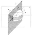
図1は、本発明の実施例1に係る非接触給電システムの構成を表すブロック図である。図2は、図1における給電コイル3及び検出コイル4の配置を示す模式図である。本実施例の非接触給電システムは、非接触給電装置1及び非接触受電装置2を備えている。
FIG. 1 is a block diagram illustrating a configuration of a non-contact power feeding system according to
非接触給電装置1は、給電コイル3及び検出コイル4を具備する給電コイルアッセンブリ6、モータ7、電源回路10、発振回路11、通電制御回路12、起電力検出回路13、位置ずれ検出回路16、移動制御回路17、位相差検出回路18、並びに位置ずれ方向検出回路19を備えている。
The non-contact
給電コイルアッセンブリ6は、図2のように給電コイル3と検出コイル4が一体的に組み込まれている。給電コイル3は、交流電流が給電され、非接触受電装置2への非接触電力送電を行うためのコイルである。通常、給電コイル3には、図2に示したような有芯コイルが使用される。尚、図2では、図を見やすくするための便宜上、給電コイル3は円筒形コイル、給電コイルのコア3aは円柱形コアとしているが、本発明に於いては、給電コイル3及び給電コイルのコア3aの形状はこれに限定されず、例えば、四角筒型コイル等を使用してもよい。尚、後述するように、非接触受電装置2の位置ずれ量の検出を容易にするため、給電コイル3及び給電コイルのコア3aの形状は、その中心軸を通る一平面に対して左右対称の形状とするのが好ましい。
As shown in FIG. 2, the power supply coil assembly 6 includes a
ここで、図2に示したように、給電コイル3の中心軸をL0、中心軸L0を含む一平面を第1の中心横断面S1、給電コイル3の中心点Oを通り且つ第1の中心横断面S1に垂直な座標軸をx軸、給電コイル3の中心点Oを通り且つ第1の中心横断面S1の面内の座標軸をy軸とする。
Here, as shown in FIG. 2, the central axis of the feeding
検出コイル4は、コイル環内に給電コイル3を内包するように配置され、非接触受電装置2の接近及び位置ずれ方向並びに位置ずれ量を検出するコイルである。検出コイル4は、非接触受電装置2の受電コイル30(後述)がない状態に於いて、誘導電流が最小となる位置に配置されている。具体的には、例えば、給電コイル3が図2のような円筒形コイルの場合、検出コイル4は、第1の中心横断面S1内に配置され、その巻軸が第1の中心横断面S1に対して垂直となる向き(x軸方向)となるように配置される。
The
図3は、受電コイル30が給電コイル3の近傍にない状態に於いて給電コイル3に通電したときに給電コイル3の周囲に作られる磁界の例を示す図である。図3は、説明のための図であり、図3においては、給電コイル3は有芯円筒形コイルとし、給電コイル3の周囲にある物体(ケーシング等)は無視している。給電コイル3が作る磁束(磁力線)は点線により示している。図3のケースでは、給電コイルが作る磁束はxy平面に対して面対称で、且つ中心軸L0に対して回転対称であるため、検出コイル4の巻軸をx軸と同軸とし、検出コイル4を第1の中心横断面S1内に配置することによって、検出コイル4に誘導される電流は最小(図3のような理想的な場合には0)となる。実際のケースでは、給電コイル3の形状や、その周囲に配置される物体(ケーシング等)の影響により、図3のような理想的な磁界分布とはならないため、検出コイル4の配向を決定する際には、給電コイル3の交流通電した状態で検出コイル4の傾きを変化させながら誘導電流を測定し、誘導電流が最小となる角度に決定すればよい。
FIG. 3 is a diagram illustrating an example of a magnetic field created around the
尚、本実施例では、非接触給電装置1は、給電コイルアッセンブリ6をx軸方向(左右方向)に平行移動させるスライダ機構(図示せず)を備えており、モータ7は、このスライダ機構を駆動することによって給電コイルアッセンブリ6をx軸方向に移動させる。尚、モータ7には、通常のステッピングモータが使用されている。
In this embodiment, the non-contact
電源回路10は、給電コイル3に通電する電力、モータ7を駆動する電力及びその他の回路を駆動する電力を供給するための直流安定化電源である。発振回路11は、給電コイル3に通電する際の周波数fの交流電圧を生成する回路である。通電制御回路12は、電源回路10から供給される直流電流を、発振回路11が生成する交流電圧により変調することにより、給電コイル3に供給する通電電流を生成する回路である。
The
起電力検出回路13は、検出コイル4に発生する起電圧(又は起電流)の強度を検出する回路である。検出コイル4に発生する起電圧(又は起電流)は交流であるため、起電力検出回路13は、これを整流する整流回路を備え、検出コイル4の起電圧(又は起電流)の強度を、整流後の検出電圧値(又はそれを増幅した電圧値)V4として出力する。位置ずれ検出回路16は、起電力検出回路13が検出する検出電圧値V4から、給電コイル3に対する受電コイル30の位置ずれ量Δxを検出する回路である。
The electromotive
位相差検出回路18は、通電制御回路12から給電コイル3に出力される電圧(又は電流)の位相φ3と、検出コイル4に発生する起電圧(又は起電流)の位相φ4との位相差Δφ43を検出する回路である。位置ずれ方向検出回路19は、位相差検出回路18が検出する位相差の正負によって、給電コイル3に対する受電コイル30の位置ずれ方向を判定する回路である。
The phase
移動制御回路17は、位置ずれ検出回路16が検出する位置ずれ量及び位置ずれ方向検出回路19が検出する位置ずれ方向に基づき、位置ずれ量が最小となるように、モータ7の駆動制御を行う回路である。移動制御回路17は、マイコン等を用いて構成することができる。
The
一方、非接触受電装置2は、受電コイル30、整流回路31、及び2次電池32を備えている。受電コイル30は、非接触給電装置2が非接触給電装置1に接近したときに、給電コイル2と磁気共鳴して、給電コイルから電力供給を受けるためのコイルである。整流回路31は、受電コイル30で発生する誘起電流を整流する回路である。2次電池32は、整流回路31が出力する直流電流により蓄電される電池である。
On the other hand, the non-contact
以上のように構成された本実施例に係る非接触給電システムにおいて、以下その動作を説明する。 The operation of the non-contact power feeding system according to the present embodiment configured as described above will be described below.
(1)受電コイルの位置ずれ量・方向と検出コイルの誘起電圧(電流)との関係
図4は、非接触給電装置1の給電コイル3に非接触受電装置2の受電コイル30が接近した際の、両コイル近傍に形成される磁界の変化を表した模式図である。尚、図4において、磁束は点線により示されている。図4では、(d),(c),(b),(a)の順に受電コイル30が給電コイル3に順次接近しており、図4(a)は、受電コイル30と給電コイル3が完全に共鳴した状態を表している。尚、図4は、直流磁場近似したものであり、実際には給電コイル3及び受電コイル30は交流通電されるため交番磁場となり、図4とは多少異なる磁力線分布となる。
(1) Relationship between position shift amount / direction of power receiving coil and induced voltage (current) of detection coil FIG. 4 shows the case where the
給電コイル3の近傍に受電コイル30がないときには、図3に示すように、検出コイル4を鎖交する鎖交磁束の磁束数はほぼゼロである。従って、検出コイル4には誘導電流は生じない。給電コイル3に受電コイル30が接近すると、給電コイル3の周囲の磁場が受電コイル30によって乱される。図4に示すとおり、受電コイル30が給電コイル3に接近すると、受電コイル30に誘導される誘導電流や受電コイル30のコアの影響により、給電コイル3の周囲の磁界が乱される。受電コイル30が給電コイル3と同軸でない位置関係のときには、受電コイル30による磁界の擾乱によって、検出コイル4を鎖交する鎖交磁束の磁束数が増加する(図4(d)(c)(b))。これにより、検出コイル4には誘導電流が発生する。受電コイル30が給電コイル3と同軸となる位置関係となった場合(図4(a))、給電コイル3の周囲の磁界は中心軸L0に対して対称となる。従って、検出コイル4を鎖交する鎖交磁束の磁束数はほぼゼロとなり、検出コイル4に生じる誘導電流もほぼゼロとなる。従って、検出コイル4に生じる誘導電流の大きさを検出することによって、給電コイル3に対する受電コイル30の位置ずれ量を検出することができる。
When there is no
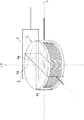
実際に、給電コイル3に交流電流を入力して、受電コイル30の位置と検出コイル4の起電圧の関係についての測定実験を行った。図5は、実験で使用した給電コイルアッセンブリ6の斜視図である。実験では、給電コイル3はコイルワイヤ3bが円筒周囲に捲回された円筒形コイルを使用した。給電コイル3のコイルコア3aは、コイルワイヤ3bを貫通する円柱状の中央軸部分の下端に、矩形板状の底板部分が連設され、さらに底板部分の左右両端に、コイルワイヤ3bの両側を囲繞する囲壁部が突設された形状に形成されている。図6は、起電圧の測定実験における、給電コイルアッセンブリ6と受電コイル30との位置関係を表す図(平面図)である。図6(a)は受電コイル30が給電コイル3の真上(中心軸L0と同軸)に位置する状態、図6(b)は受電コイル30が給電コイル3の右側にずれて位置する状態、図6(c)は受電コイル30が給電コイル3の左側にずれて位置する状態である。
Actually, an alternating current was input to the
図7は、図5の測定位置B,Cにおける給電コイル3,受電コイル30,検出コイル4の電圧波形である。図7(a)は相対位置A(図6(a))に受電コイル30を置いた場合の電圧波形、図7(b)は相対位置B(図6(b))に受電コイル30を置いた場合の電圧波形、図7(c)は相対位置C(図6(c))に受電コイル30を置いた場合の電圧波形を表す。また、図7(a)〜(c)において、チャネル1(最下部)の波形が給電コイル3に入力された電圧波形、チャネル2(下から2番目)の波形が受電コイル30に誘起された電圧波形、チャネル4(最上部)の波形が検出コイル4に誘起された電圧波形である。
FIG. 7 shows voltage waveforms of the feeding
図7に示すように、受電コイル30が給電コイル3と同軸位置にある場合、検出コイル4には誘導電圧は発生しない(図7(a))。すなわち、誘導電圧波形の強度は最小となる。受電コイル30がx軸方向に左にずれると、検出コイル4には、給電コイル3に入力された電圧波形に対して、位相が90度進んだ誘導電圧が発生する。逆に、受電コイル30がx軸方向に右にずれると、検出コイル4には、給電コイル3に入力された電圧波形に対して、位相が90度遅れた誘導電圧が発生する。従って、給電コイル3に入力される電圧波形に対する検出コイル4に誘導される誘導電圧の位相の正負を検出することによって、給電コイル3に対する受電コイル30の位置ずれ方向を検出することが可能であることが分かる。
As shown in FIG. 7, when the
尚、受電コイル30のずれ方向に対して、検出コイル4の誘導電圧波形の位相が進むか遅れるかは、給電コイル3と受電コイル30の巻き方向に依存する。
Whether the phase of the induced voltage waveform of the
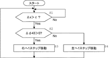
(2)非接触給電装置1の動作
次に、図1の非接触給電装置1について、具体的な位置ずれ補正制御における動作を説明する。図8は、非接触給電装置1の移動制御回路17の位置ずれ補正制御動作を表すフローチャートである。尚、ここでは、給電コイル3に対し受電コイル30がx軸方向に左にずれると、検出コイル4には位相が90度進んだ誘導電圧が発生するものとする。
(2) Operation of Non-Contact
まず、ステップS1において、移動制御回路17は、位置ずれ検出回路16が検出する位置ずれ量Δxが、所定の閾値εよりも大きいか否かを判定する。Δx≦εの場合には、ステップS1の判定動作を繰り返す。Δx>εの場合には、次のステップS2に進む。
First, in step S1, the
次に、ステップS2において、移動制御回路17は、位相差検出回路18が検出する位相差Δφ43の正負を判定する。ここで、Δφ43が正の場合には、移動制御回路17は、給電コイルアッセンブリ6が右向きに移動する回転方向に、モータ7を1ステップ回転させ(S3)、Δφ43が負の場合には、移動制御回路17は、給電コイルアッセンブリ6が左向きに移動する回転方向に、モータ7を1ステップ回転さる(S4)。そして、再びステップS1へ戻る。
Next, in step S2, the
この動作によって、給電コイルアッセンブリ6は、受電コイル30の位置に追随して、給電コイル3が受電コイル30の真下の位置となるように位置制御がされる。
By this operation, the feeding coil assembly 6 is controlled to follow the position of the
尚、本実施例に於いては、給電コイル3に対する受電コイル30のずれのうち、y方向のずれについては無視できると仮定した。これは、例えば、本実施例の非接触給電システムを電動車椅子の充電器に応用した場合において、充電時に電動車椅子の車輪を所定のレール上に乗せてセットした場合などを想定している。この場合、レールに沿った方向をx軸とし、x軸方向の位置ずれのみを考慮すればよい。
In this embodiment, it is assumed that the deviation in the y direction among the deviations of the
また、通電制御回路12は、位置ずれの調整を行っている間は、位置ずれ検出のために給電コイル3に間欠的に通電し、位置ずれ検出回路16が検出する位置ずれ量Δxが、Δx≦εとなった場合に、連続通電するように切り替えるように構成してもよい。
Further, the
図9は、本発明の実施例2に係る非接触給電システムの構成を表すブロック図である。図10は、図9における給電コイル3及び検出コイル4a,4bの配置を示す模式図である。図11は、図10の給電コイル3及び検出コイル4a,4bの具体的な構成例を表す図である。
FIG. 9 is a block diagram illustrating the configuration of the non-contact power feeding system according to the second embodiment of the present invention. FIG. 10 is a schematic diagram showing the arrangement of the feeding
本実施例の非接触給電システムにおいては、実施例1と比較して、図1の検出コイル4、起電力検出回路13、位置ずれ検出回路16、位相差検出回路18及び位置ずれ方向検出回路19が、それぞれ2つずつ(図9の検出コイル4a,4b、起電力検出回路13a,13b、位置ずれ検出回路16a,16b、位相差検出回路18a,18b及び位置ずれ方向検出回路19a,19b)設けられ、検出コイル4a,4bは互いに直交して配設された点、給電コイルアッセンブリ6を駆動するスライダ機構(図示せず)がx軸に加えてy軸方向にも平行移動を可能とし、このスライダ機構を駆動するモータ7として、x軸方向のモータ7a及びy軸方向のモータ7bを設けた点、移動制御回路17は位置ずれ検出回路16及び位置ずれ方向検出回路19a,19bが検出する位置ずれ量及びx軸及びy軸方向の位置ずれ向きに基づき、位置ずれ量が最小となるように、2つのモータ7a,7bの駆動制御を行う点が異なっている。それ以外は実施例1と同様である。
In the non-contact power feeding system of the present embodiment, compared to the first embodiment, the
本実施例の給電コイルアッセンブリ6は、図10,図11のように給電コイル3と検出コイル4a,4bとが一体的に組み込まれている。図10に示したように、給電コイル3の中心軸をL0、中心軸L0を含む一平面を第1の中心横断面S1、中心軸L0を含み第1の中心横断面S1に垂直な平面を第2の中心横断面S2、給電コイル3の中心点Oを通り且つ第1の中心横断面S1に垂直な座標軸をx軸、給電コイル3の中心点Oを通り且つ第2の中心横断面S2に垂直な座標軸をy軸とする。
As shown in FIGS. 10 and 11, the feeding coil assembly 6 of the present embodiment has the feeding
検出コイル4a,4bは、ともにコイル環内に給電コイル3を内包するように互いに直交して配置され、非接触受電装置2の受電コイル30(後述)がない状態に於いて、誘導電流が最小となる位置に配置されている。具体的には、給電コイル3が図10のような円筒形コイルの場合、検出コイル4aは、実施例1の検出コイル4と同様に、第1の中心横断面S1内に配置され、その巻軸が第1の中心横断面S1に対して垂直となる向き(x軸方向)となるように配向されている。検出コイル4bは、第2の中心横断面S2内に配置され、その巻軸が第2の中心横断面S2に対して垂直となる向き(y軸方向)となるように配向される。
The detection coils 4a and 4b are arranged orthogonally to each other so as to enclose the
尚、本発明に於いては、給電コイル3及び給電コイルのコア3aの形状はこれに限定されず、例えば、四角筒型コイル等を使用してもよい。尚、後述するように、非接触受電装置2の位置ずれ量の検出を容易にするため、給電コイル3及び給電コイルのコア3aの形状は、その中心軸を通る一平面に対して左右対称の形状とするのが好ましい。
In the present invention, the shape of the feeding
このように、本実施例の非接触給電システムにおいては、互いに直交する2つの検出コイル4a,4bを備えたことにより、給電コイル3に対する受電コイル30の位置ずれのx軸方向成分及びy軸方向成分を検出することが可能となる。そして、位置ずれ検出回路16a,16b及び位置ずれ方向検出回路19a,19bにより検出した2方向(x軸方向及びy軸方向)の位置ずれ量及び方向に基づき、移動制御回路17がモータ7a,7bを制御して、給電コイルアッセンブリ6の2方向の位置調整を行い、最適な位置に給電コイル3を移動させて給電を行うことができる。尚、移動制御回路17の制御動作は、x軸方向及びy軸方向の各方向で独立に行われ、各方向に対して実施例1の図8で説明したプロセスと同様のプロセスで行えばよい。
Thus, in the non-contact power feeding system of the present embodiment, the two
図12は、本発明の実施例3に係る非接触給電システムの構成を表すブロック図である。図13は、図12における給電コイルアッセンブリ6を示す模式図である。本実施例において、非接触受電装置2の構成は実施例1,2と同様である。また、非接触給電装置1については、実施例2と同様の部分については同符号を付している。本実施例の非接触給電装置1を、実施例2と比較すると、検出コイル5、起電力検出回路13c、位相差検出回路18c、共振周波数制御回路20を備えた点において相違している。
FIG. 12 is a block diagram illustrating a configuration of a non-contact power feeding system according to
本実施例の給電コイルアッセンブリ6は、図13に示したように、実施例2で説明した直交配置された2つの検出コイル4a,4bに加えて、給電コイル3の側方に近接して配置された、検出コイル4bと同軸の検出コイル5を備えている。ここで、検出コイル5の巻軸は、給電コイル3の近傍に受電コイル30が存在しない状態に於いて、給電コイル3が作る磁束に対し垂直となる向きとなっている。従って、給電コイル3の近傍に受電コイル30が存在しないときは、給電コイル3が作る磁束の内、検出コイル5を鎖交する磁束数は略0であり、検出コイル5には起電圧(又は起電流)は発生しない。
As shown in FIG. 13, the power supply coil assembly 6 of the present embodiment is arranged close to the side of the
一方、給電コイル3の近傍に受電コイル30が接近すると、給電コイル3の周囲の磁場が受電コイル30の影響によって乱されるため(図4参照)、検出コイル5を鎖交する磁束数は0ではなくなる。従って、検出コイル5には起電圧(又は起電流)が発生する。給電コイル3の真上の給電コイル3と同軸となる位置に受電コイル30が接近した場合、実施例1,2で説明した通り、検出コイル4a,4bの起電圧(又は起電流)は略0となる。一方、検出コイル5は、給電コイル3の中心Oから偏倚して設けられているため、このとき検出コイル5を鎖交する磁束数は0ではなく、起電圧(又は起電流)が発生する。この起電圧(又は起電流)の位相φ5は、理想的な場合(給電コイル3の通電周波数が、給電コイル3と受電コイル30の間の共振周波数に一致する場合)には給電コイル3に通電される電流の位相φ3に対して丁度90度ずれた状態となる。
On the other hand, when the
従って、起電力検出回路13cが検出する検出電圧値(又はそれを増幅した電圧値)V5が所定の閾値Vth5以上となったか否かを判定することで、給電コイル3の近傍に受電コイル30が接近したか否かを判定することができる。
Accordingly, by determining whether or not the detected voltage value (or a voltage value obtained by amplifying it) V5 detected by the electromotive force detection circuit 13c is equal to or greater than the predetermined threshold value Vth5, the
また、実際の非接触給電システムにおいては、給電コイル3や受電コイル30の経時劣化等により、給電コイル3や受電コイル30のインダクタンスが長い時間の間に変化する。従って、給電コイル3と受電コイル30の間の共振周波数は、使用期間が長くなると設計値からずれる現象がみられる。給電コイル3の通電周波数は共振周波数からずれるに伴い、給電コイル3の通電電流の位相φ3に対する検出コイル5の誘起電流の位相φ5の位相差Δφ53=φ5−φ3の絶対値が90度からシフトする。従って、位相差|Δφ53|を検査することによって、共振周波数に対する給電コイル3の通電周波数のずれを検出することが可能となる。
In an actual non-contact power supply system, the inductance of the
そこで、共振周波数制御回路20は、位相差検出回路18cが検出する位相差に基づき、誘起電圧V5の位相と給電電圧V3の位相との位相差が90度となるように、発振回路11の周波数制御を行う。具体的には、発振回路11には電圧制御発振器(VCO)、位相差検出回路18cには位相差を電圧として出力する位相比較器(PC)、共振周波数制御回路19には位相比較器の出力から電圧制御発振器の制御電圧を生成するローパスフィルタ(LPF)を使用し、VCO,PC,LPFにより周波数負帰還回路(Phase Locked Loop:PLL)を構成すればよい。
Therefore, the resonant
図14は、図12の非接触給電装置1の移動制御回路17の位置ずれ補正制御動作及び通電制御回路12の通電モード切替動作を表すフローチャートである。移動制御回路17の位置ずれ補正制御は、x軸方向とy軸方向とで独立で実行され、図14(a)では、x軸方向の位置ずれ補正制御のみを示す。y軸方向も図14(a)と同様である。
FIG. 14 is a flowchart showing the misalignment correction control operation of the
まず、ステップS10において、起電力検出回路13cは、検出コイル5の誘起電圧の検出値V5が、所定の閾値Vth5よりも大きいか否かを判定する。ここで、閾値Vth5は、検出コイル5に誘起電圧(誘起電流)が発生したか否かを判定するための閾値であり、十分小さい値に設定される。実際には、給電コイル3の周囲には、ケーシング等の様々な物体が配置されるため、受電コイル30が給電コイル3の近傍に存在しない場合に於いても、検出コイル5の誘起電圧(誘起電流)は完全には0にはならない。閾値Vth5はこのノイズ的に発生する誘起電圧(誘起電流)による誤判定を防止するために設定される。V5<Vth5の場合、受電コイル30が給電コイル3の近傍に存在しないと判定し、通電制御回路12は、通電モードを「給電待機モード」に設定し(S11)、ステップS10に戻る。一方、V5≧Vth5の場合、次のステップS12に移行する。
First, in step S10, the electromotive force detection circuit 13c determines whether or not the detection value V5 of the induced voltage of the
ここで、通電制御回路12の通電モードには「給電待機モード」と「給電モード」がある。「給電待機モード」は、通電制御回路12が一定の時間間隔(例えば5秒間隔)で、間歇的にパルス状の通電を行う通電モードである。この給電待機モードでは、受電コイル30の存在の検出のみを目的とした通電である。一方、「給電モード」は、通電制御回路12が連続的に通電を行う通電モードである。
Here, the energization modes of the
ステップS12において、移動制御回路17は、位置ずれ検出回路16aが検出する位置ずれ量Δxが、所定の閾値εよりも大きいか否かを判定する。Δx≦εの場合には、後述の給電モード移行判定処理(図14(b))を行った後(S13)、ステップS10の判定動作に戻る。Δx>εの場合には、次のステップS14に進む。
In step S12, the
次に、ステップS14において、移動制御回路17は、位相差検出回路18aが検出する位相差Δφ43の正負を判定する。ここで、Δφ43が正の場合には、移動制御回路17は、給電コイルアッセンブリ6がx軸に沿って右向きに移動する回転方向に、モータ7aを1ステップ回転させ(S15)、Δφ43が負の場合には、移動制御回路17は、給電コイルアッセンブリ6がx軸に沿って左向きに移動する回転方向に、モータ7aを1ステップ回転さる(S16)。そして、再びステップS12へ戻る。
Next, in step S14, the
この動作によって、給電コイルアッセンブリ6は、受電コイル30のx軸方向の位置に追随して、給電コイル3が受電コイル30のx軸方向について真下の位置となるように位置制御がされる。y軸方向についても、図14(a)と同様に位置調整が行われる。
By this operation, the feed coil assembly 6 is controlled in position so that the
ステップS13の給電モード移行判定処理は、図14(b)のフローにより実行される。まず、通電制御回路12は、位置ずれ検出回路16aが検出する位置ずれ量Δxと、位置ずれ検出回路16bが検出する位置ずれ量Δyが、共に所定の閾値ε以下となったか否かを判定し(S21)、(Δx≦ε∧Δy≦ε)の場合には、通電制御回路12は通電モードを「給電モード」に設定する。そうでない場合には、「給電待機モード」を維持する。これにより、給電コイル3が受電コイル30のx軸方向及びy軸方向について真下の位置となったときに給電が開始されることになる。
The power supply mode transition determination process in step S13 is executed according to the flow in FIG. First, the
図15は、本発明の実施例4に係る非接触給電システムの構成を表すブロック図である。本実施例では、実施例2の非接触給電装置において使用した位置ずれ検出機構と位置調節機構を、非接触受電装置2の側に適用したものである。従って、実施例2(図9参照)と同様の構成部分については同符号を付して説明は省略する。また、非接触給電装置1の側については、内部構成は実施例3と同様であるため省略している。尚、非接触受電装置2の側では、送電は行わないため、図9における電源回路10,発振回路11,通電制御回路12はない。このように、非接触受電装置2の側にも全く同様に適用することで、非接触受電装置2の側で位置ずれ検出と位置調整を行うことが可能となる。
FIG. 15 is a block diagram illustrating a configuration of a non-contact power feeding system according to
尚、本実施例では、非接触受電装置2を電気自動車や電動車いすに適用した例を想定しており、非接触受電装置2の全体を移動するための車輪及びその駆動機構(モータ駆動回路33及びモータ34)を有する。車輪はモータ34により駆動され、非接触受電装置2の位置調節が行われる。
In this embodiment, it is assumed that the non-contact
また、本実施例では、非接触受電装置2の側に、実施例2の非接触給電装置において使用した位置ずれ検出機構と位置調節機構を適用した例を示したが、本発明では、非接触受電装置2の側に、実施例3の非接触給電装置において使用した位置ずれ検出機構と位置調節機構を適用することもできる。
Further, in this embodiment, an example in which the misalignment detection mechanism and the position adjustment mechanism used in the non-contact power feeding apparatus of
1 非接触給電装置
2 非接触受電装置
3 給電コイル
3a コイルコア
3b コイルワイヤ
4,4a,4b 検出コイル
5 検出コイル
6 給電コイルアッセンブリ
7,7a,7b モータ
10 電源回路
11 発振回路
12 通電制御回路
13,13a,13b,13c 起電力検出回路
16,16a,16b 位置ずれ検出回路
17 移動制御回路
18,18a,18b,18c 位相差検出回路
19,19a,19b 位置ずれ方向検出回路
20 共振周波数制御回路
30 受電コイル
31 整流回路
32 2次電池
DESCRIPTION OF
Claims (6)
前記給電コイルの中心軸を含む面である第1の中心横断面の面内に、巻軸が前記第1の中心横断面に対し垂直となる向きに配設された第1の検出コイルを備え、
前記第1の検出コイルは、該第1の検出コイルのコイル環内に前記給電コイルを内包するように配置されたものであり、
前記第1の検出コイルに発生する起電圧又は起電流の強度を検出する第1の起電力検出手段と、
前記給電コイルに供給される電圧又は電流の位相と前記第1の検出コイルに発生する起電圧又は起電流の位相との位相差を検出する第1の位相差検出手段と、
前記第1の起電力検出手段が検出する起電圧又は起電流の強度を閾値判定することにより、前記給電コイルに対する前記受電コイルの位置ずれの有無を判定する第1の位置ずれ検出手段と、
前記第1の位相差検出手段が検出する位相差により、前記第1の検出コイルの中心軸方向(以下「x軸方向」という。)の位置ずれ向きを検出する第1の位置ずれ方向検出手段と、を備えたことを特徴とする非接触給電装置。 A non-contact power supply device including a power supply coil to which AC power is supplied, and a non-contact power supply device that is detachably attached to the power supply coil and includes a power reception coil that resonates with the power supply coil and receives power supply from the power supply coil. A non-contact power feeding device used in a non-contact power feeding system including a power receiving device,
A first detection coil having a winding axis disposed in a direction perpendicular to the first central cross section in a plane of a first central cross section that is a plane including the central axis of the power supply coil; ,
The first detection coil is disposed so as to enclose the feeding coil in a coil ring of the first detection coil,
First electromotive force detection means for detecting the intensity of an electromotive voltage or an electromotive current generated in the first detection coil;
First phase difference detection means for detecting a phase difference between the phase of the voltage or current supplied to the power supply coil and the phase of the electromotive voltage or current generated in the first detection coil;
A first misalignment detecting means for determining the presence or absence of misalignment of the power receiving coil with respect to the power feeding coil by determining a threshold value of the intensity of the electromotive voltage or current detected by the first electromotive force detecting means;
First misalignment direction detecting means for detecting the misalignment direction of the first detection coil in the central axis direction (hereinafter referred to as “x-axis direction”) based on the phase difference detected by the first phase difference detecting means. And a non-contact power feeding device.
前記第2の検出コイルは、該第2の検出コイルのコイル環内に前記給電コイルを内包するように配置されたものであり、
前記第2の検出コイルに発生する起電圧又は起電流の強度を検出する第2の起電力検出手段と、
前記給電コイルに供給される電圧又は電流の位相と前記第2の検出コイルに発生する起電圧又は起電流の位相との位相差を検出する第2の位相差検出手段と、
前記第2の起電力検出手段が検出する起電圧又は起電流の強度を閾値判定することにより、前記給電コイルに対する前記受電コイルの位置ずれの有無を判定する第2の位置ずれ検出手段と、
前記第2の位相差検出手段が検出する位相差により、前記第2の検出コイルの中心軸方向(以下「y軸方向」という。)の位置ずれ向きを検出する第2の位置ずれ方向検出手段と、を備えたことを特徴とする請求項1記載の非接触給電装置。 The winding axis is in a direction perpendicular to the second central cross section in a plane of the second central cross section that includes the central axis of the feeding coil and is a plane perpendicular to the first central cross section. A second detection coil disposed;
The second detection coil is disposed so as to enclose the feeding coil in a coil ring of the second detection coil,
Second electromotive force detection means for detecting the intensity of an electromotive voltage or an electromotive current generated in the second detection coil;
Second phase difference detection means for detecting a phase difference between the phase of the voltage or current supplied to the power supply coil and the phase of the electromotive voltage or current generated in the second detection coil;
A second misalignment detecting means for determining whether or not the power receiving coil is misaligned with respect to the power feeding coil by determining a threshold value of the intensity of the electromotive voltage or electromotive current detected by the second electromotive force detecting means;
Second misalignment direction detecting means for detecting the misalignment direction of the second detection coil in the central axis direction (hereinafter referred to as “y-axis direction”) based on the phase difference detected by the second phase difference detecting means. And a non-contact power feeding device according to claim 1.
前記給電コイルに供給される電圧又は電流の位相と前記第3の検出コイルに発生する起電圧又は起電流の位相との位相差を検出する第3の位相差検出手段と、
前記第3の位相差検出手段により検出される位相差が所定の値となるように、前記給電コイルに供給される電圧又は電流の周波数を制御する共振周波数制御手段と、を備えたことを特徴とする請求項1又は2記載の非接触給電装置。 A third detection coil is disposed on the side of the power supply coil in a direction perpendicular to the magnetic flux generated by the power supply coil when the winding axis is not close to the power supply coil. When,
Third phase difference detection means for detecting a phase difference between the phase of the voltage or current supplied to the feeding coil and the phase of the electromotive voltage or current generated in the third detection coil;
Resonance frequency control means for controlling the frequency of the voltage or current supplied to the power supply coil so that the phase difference detected by the third phase difference detection means becomes a predetermined value. The contactless power supply device according to claim 1 or 2.
の起電力検出手段と、
前記第3の起電力検出手段が検出する起電圧又は起電流の強度を閾値判定することにより、前記給電コイルの近傍に前記受電コイルが存在するか否かを判定する存否検出手段と、を備えたことを特徴とする請求項3記載の非接触給電装置。 A third for detecting the intensity of the electromotive voltage or electromotive current generated in the third detection coil;
Electromotive force detection means,
Presence / absence detecting means for determining whether or not the power receiving coil is present in the vicinity of the power supply coil by determining a threshold value of the intensity of the electromotive voltage or electromotive current detected by the third electromotive force detecting means. The non-contact electric power feeder of Claim 3 characterized by the above-mentioned.
前記受電コイルの中心軸を含む面である第1の中心横断面の面内に、巻軸が前記第1の中心横断面に対し垂直となる向きに配設された第1の検出コイルを備え、
前記第1の検出コイルは、該第1の検出コイルのコイル環内に前記受電コイルを内包するように配置されたものであり、
前記第1の検出コイルに発生する起電圧又は起電流の強度を検出する第1の起電力検出手段と、
前記給電コイルが作る交番磁場により前記受電コイルに誘導される電圧又は電流の位相と前記第1の検出コイルに発生する起電圧又は起電流の位相との位相差を検出する第1の位相差検出手段と、
前記第1の起電力検出手段が検出する起電圧又は起電流の強度を閾値判定することにより、前記給電コイルに対する前記受電コイルの位置ずれの有無を判定する第1の位置ずれ検出手段と、
前記第1の位相差検出手段が検出する位相差により、前記第1の検出コイルの中心軸方向(以下「x軸方向」という。)の位置ずれ向きを検出する第1の位置ずれ方向検出手段と、を備えたことを特徴とする非接触受電装置。 A non-contact power supply device including a power supply coil to which AC power is supplied, and a non-contact power supply device that is detachably attached to the power supply coil and includes a power reception coil that resonates with the power supply coil and receives power supply from the power supply coil. A non-contact power receiving device used in a non-contact power feeding system including a power receiving device,
A first detection coil having a winding axis disposed in a direction perpendicular to the first central cross section in a plane of a first central cross section that is a plane including the central axis of the power receiving coil; ,
The first detection coil is disposed so as to enclose the power receiving coil in a coil ring of the first detection coil,
First electromotive force detection means for detecting the intensity of an electromotive voltage or an electromotive current generated in the first detection coil;
First phase difference detection for detecting a phase difference between a phase of voltage or current induced in the power receiving coil by an alternating magnetic field generated by the power feeding coil and a phase of electromotive voltage or current generated in the first detection coil Means,
A first misalignment detecting means for determining the presence or absence of misalignment of the power receiving coil with respect to the power feeding coil by determining a threshold value of the intensity of the electromotive voltage or current detected by the first electromotive force detecting means;
First misalignment direction detecting means for detecting the misalignment direction of the first detection coil in the central axis direction (hereinafter referred to as “x-axis direction”) based on the phase difference detected by the first phase difference detecting means. And a non-contact power receiving device.
前記第2の検出コイルは、該第2の検出コイルのコイル環内に前記受電コイルを内包するように配置されたものであり、
前記第2の検出コイルに発生する起電圧又は起電流の強度を検出する第2の起電力検出手段と、
前記給電コイルが作る交番磁場により前記受電コイルに誘導される電圧又は電流の位相と前記第2の検出コイルに発生する起電圧又は起電流の位相との位相差を検出する第2の位相差検出手段と、
前記第2の起電力検出手段が検出する起電圧又は起電流の強度を閾値判定することにより、前記給電コイルに対する前記受電コイルの位置ずれの有無を判定する第2の位置ずれ検出手段と、
前記第2の位相差検出手段が検出する位相差により、前記第2の検出コイルの中心軸方向(以下「y軸方向」という。)の位置ずれ向きを検出する第2の位置ずれ方向検出手段と、を備えたことを特徴とする請求項5記載の非接触受電装置。 The winding axis is in a direction perpendicular to the second central cross section in a plane of the second central cross section that includes the central axis of the power receiving coil and is perpendicular to the first central cross section. A second detection coil disposed;
The second detection coil is disposed so as to enclose the power receiving coil in a coil ring of the second detection coil,
Second electromotive force detection means for detecting the intensity of an electromotive voltage or an electromotive current generated in the second detection coil;
Second phase difference detection for detecting a phase difference between the phase of the voltage or current induced in the power receiving coil by the alternating magnetic field generated by the power feeding coil and the phase of the electromotive voltage or current generated in the second detection coil. Means,
A second misalignment detecting means for determining whether or not the power receiving coil is misaligned with respect to the power feeding coil by determining a threshold value of the intensity of the electromotive voltage or electromotive current detected by the second electromotive force detecting means;
Second misalignment direction detecting means for detecting the misalignment direction of the second detection coil in the central axis direction (hereinafter referred to as “y-axis direction”) based on the phase difference detected by the second phase difference detecting means. And a non-contact power receiving device according to claim 5.
Priority Applications (1)
| Application Number | Priority Date | Filing Date | Title |
|---|---|---|---|
| JP2015113203A JP6507036B2 (en) | 2015-06-03 | 2015-06-03 | Non-contact power feeding device and non-contact power receiving device |
Applications Claiming Priority (1)
| Application Number | Priority Date | Filing Date | Title |
|---|---|---|---|
| JP2015113203A JP6507036B2 (en) | 2015-06-03 | 2015-06-03 | Non-contact power feeding device and non-contact power receiving device |
Publications (2)
| Publication Number | Publication Date |
|---|---|
| JP2016226236A true JP2016226236A (en) | 2016-12-28 |
| JP6507036B2 JP6507036B2 (en) | 2019-04-24 |
Family
ID=57746087
Family Applications (1)
| Application Number | Title | Priority Date | Filing Date |
|---|---|---|---|
| JP2015113203A Expired - Fee Related JP6507036B2 (en) | 2015-06-03 | 2015-06-03 | Non-contact power feeding device and non-contact power receiving device |
Country Status (1)
| Country | Link |
|---|---|
| JP (1) | JP6507036B2 (en) |
Cited By (2)
| Publication number | Priority date | Publication date | Assignee | Title |
|---|---|---|---|---|
| JP2018161012A (en) * | 2017-03-23 | 2018-10-11 | 東芝テック株式会社 | Non-contact power transmission device and power transmission device |
| US20210384772A1 (en) * | 2018-05-01 | 2021-12-09 | Global Energy Transmission, Co. | Systems and methods for wireless power transferring |
Citations (11)
| Publication number | Priority date | Publication date | Assignee | Title |
|---|---|---|---|---|
| JPS62135789A (en) * | 1985-12-09 | 1987-06-18 | Toyota Motor Corp | Vehicle detecting device |
| JPS62175687A (en) * | 1986-01-30 | 1987-08-01 | Osaka Gas Co Ltd | Detector for object placed in concealed place |
| JPH03119207U (en) * | 1990-03-16 | 1991-12-09 | ||
| JP2009089465A (en) * | 2007-09-27 | 2009-04-23 | Panasonic Corp | Charger and charging system |
| JP2009539090A (en) * | 2006-06-02 | 2009-11-12 | ソシエテ プリムス フランセーズ | Detection system suitable for identifying and tracking buried pipes or other objects embedded in the ground or embedded in civil engineering structures |
| US20100164499A1 (en) * | 2006-09-04 | 2010-07-01 | Crawford Thomas M | Apparatus for and method of detecting a conductive object |
| US20100201315A1 (en) * | 2007-09-27 | 2010-08-12 | Panasonic Corporation | Electronic device, charger, and charging device |
| US20110049997A1 (en) * | 2009-09-03 | 2011-03-03 | Tdk Corporation | Wireless power feeder and wireless power transmission system |
| JP2011083178A (en) * | 2009-09-08 | 2011-04-21 | Tdk Corp | Wireless power feeder and wireless power transmission system |
| US20120161533A1 (en) * | 2010-12-28 | 2012-06-28 | Tdk Corporation | Wireless power feeder, wireless power receiver, and wireless power transmission system |
| WO2014156655A1 (en) * | 2013-03-29 | 2014-10-02 | 日産自動車株式会社 | Contactless power transmission device |
-
2015
- 2015-06-03 JP JP2015113203A patent/JP6507036B2/en not_active Expired - Fee Related
Patent Citations (12)
| Publication number | Priority date | Publication date | Assignee | Title |
|---|---|---|---|---|
| JPS62135789A (en) * | 1985-12-09 | 1987-06-18 | Toyota Motor Corp | Vehicle detecting device |
| JPS62175687A (en) * | 1986-01-30 | 1987-08-01 | Osaka Gas Co Ltd | Detector for object placed in concealed place |
| JPH03119207U (en) * | 1990-03-16 | 1991-12-09 | ||
| JP2009539090A (en) * | 2006-06-02 | 2009-11-12 | ソシエテ プリムス フランセーズ | Detection system suitable for identifying and tracking buried pipes or other objects embedded in the ground or embedded in civil engineering structures |
| US20100164499A1 (en) * | 2006-09-04 | 2010-07-01 | Crawford Thomas M | Apparatus for and method of detecting a conductive object |
| JP2009089465A (en) * | 2007-09-27 | 2009-04-23 | Panasonic Corp | Charger and charging system |
| US20100201315A1 (en) * | 2007-09-27 | 2010-08-12 | Panasonic Corporation | Electronic device, charger, and charging device |
| US20110049997A1 (en) * | 2009-09-03 | 2011-03-03 | Tdk Corporation | Wireless power feeder and wireless power transmission system |
| JP2011083178A (en) * | 2009-09-08 | 2011-04-21 | Tdk Corp | Wireless power feeder and wireless power transmission system |
| US20120161533A1 (en) * | 2010-12-28 | 2012-06-28 | Tdk Corporation | Wireless power feeder, wireless power receiver, and wireless power transmission system |
| WO2012090701A1 (en) * | 2010-12-28 | 2012-07-05 | Tdk株式会社 | Wireless power feeder, wireless power receiver, and wireless power transmission system |
| WO2014156655A1 (en) * | 2013-03-29 | 2014-10-02 | 日産自動車株式会社 | Contactless power transmission device |
Cited By (2)
| Publication number | Priority date | Publication date | Assignee | Title |
|---|---|---|---|---|
| JP2018161012A (en) * | 2017-03-23 | 2018-10-11 | 東芝テック株式会社 | Non-contact power transmission device and power transmission device |
| US20210384772A1 (en) * | 2018-05-01 | 2021-12-09 | Global Energy Transmission, Co. | Systems and methods for wireless power transferring |
Also Published As
| Publication number | Publication date |
|---|---|
| JP6507036B2 (en) | 2019-04-24 |
Similar Documents
| Publication | Publication Date | Title |
|---|---|---|
| JP5488760B2 (en) | Wireless power feeding device, wireless power receiving device, and wireless power transmission system | |
| US9595834B2 (en) | Wireless power transmission system and power transmission device | |
| JP5994771B2 (en) | Wireless power feeding device, wireless power receiving device, wireless power transmission system and coil | |
| JP5522271B2 (en) | Wireless power feeding device, wireless power receiving device, wireless power transmission system | |
| JP5953785B2 (en) | Wireless power supply apparatus and wireless power transmission system | |
| US8922064B2 (en) | Wireless power feeder, wireless power receiver, and wireless power transmission system, and coil | |
| JP5549745B2 (en) | Wireless power supply apparatus and wireless power transmission system | |
| US10374461B2 (en) | Power receiver and power transmitting system | |
| KR101789457B1 (en) | Power transmission apparatus | |
| US9270124B2 (en) | Contactless power supply device | |
| JP6416567B2 (en) | Wireless power feeder | |
| CN105765828A (en) | A method of and apparatus for detecting coil alignment error in wireless inductive power transmission | |
| JP5389735B2 (en) | Power transmission instruction transmission device | |
| JP5796444B2 (en) | Non-contact power feeding device | |
| JPWO2018221532A1 (en) | Power transmission device, wireless power transmission system, and control device | |
| JP2016226236A (en) | Non-contact power supply device and non-contact power reception device | |
| US10476311B2 (en) | Power receiver and power transmitting system | |
| JP2013251956A (en) | Power transport method | |
| JPH11206043A (en) | Non-contact type power feeding apparatus | |
| JP2020156307A (en) | Non-contact power supply device | |
| US20240128800A1 (en) | Contactless Power Feeding Facility | |
| JP2016063698A (en) | Wireless power supply device | |
| JP2017147911A (en) | Opposite side power transfer coil detection device and non-contact power supply device | |
| JP2016189659A (en) | Coil module, power feeding device, power reception device and non-contact power transmission device | |
| JP2018207783A (en) | Wireless power supply device |
Legal Events
| Date | Code | Title | Description |
|---|---|---|---|
| A621 | Written request for application examination |
Free format text: JAPANESE INTERMEDIATE CODE: A621 Effective date: 20180521 |
|
| A977 | Report on retrieval |
Free format text: JAPANESE INTERMEDIATE CODE: A971007 Effective date: 20190222 |
|
| TRDD | Decision of grant or rejection written | ||
| A01 | Written decision to grant a patent or to grant a registration (utility model) |
Free format text: JAPANESE INTERMEDIATE CODE: A01 Effective date: 20190305 |
|
| A61 | First payment of annual fees (during grant procedure) |
Free format text: JAPANESE INTERMEDIATE CODE: A61 Effective date: 20190401 |
|
| R150 | Certificate of patent or registration of utility model |
Ref document number: 6507036 Country of ref document: JP Free format text: JAPANESE INTERMEDIATE CODE: R150 |
|
| LAPS | Cancellation because of no payment of annual fees |