JP2016224204A - Tremor correction device, optical device, imaging device, and tremor correction method - Google Patents
Tremor correction device, optical device, imaging device, and tremor correction method Download PDFInfo
- Publication number
- JP2016224204A JP2016224204A JP2015109363A JP2015109363A JP2016224204A JP 2016224204 A JP2016224204 A JP 2016224204A JP 2015109363 A JP2015109363 A JP 2015109363A JP 2015109363 A JP2015109363 A JP 2015109363A JP 2016224204 A JP2016224204 A JP 2016224204A
- Authority
- JP
- Japan
- Prior art keywords
- shake
- detection signal
- image
- calculated
- unit
- Prior art date
- Legal status (The legal status is an assumption and is not a legal conclusion. Google has not performed a legal analysis and makes no representation as to the accuracy of the status listed.)
- Granted
Links
Images


Classifications
-
- G—PHYSICS
- G03—PHOTOGRAPHY; CINEMATOGRAPHY; ANALOGOUS TECHNIQUES USING WAVES OTHER THAN OPTICAL WAVES; ELECTROGRAPHY; HOLOGRAPHY
- G03B—APPARATUS OR ARRANGEMENTS FOR TAKING PHOTOGRAPHS OR FOR PROJECTING OR VIEWING THEM; APPARATUS OR ARRANGEMENTS EMPLOYING ANALOGOUS TECHNIQUES USING WAVES OTHER THAN OPTICAL WAVES; ACCESSORIES THEREFOR
- G03B5/00—Adjustment of optical system relative to image or object surface other than for focusing
-
- G—PHYSICS
- G02—OPTICS
- G02B—OPTICAL ELEMENTS, SYSTEMS OR APPARATUS
- G02B27/00—Optical systems or apparatus not provided for by any of the groups G02B1/00 - G02B26/00, G02B30/00
- G02B27/64—Imaging systems using optical elements for stabilisation of the lateral and angular position of the image
- G02B27/646—Imaging systems using optical elements for stabilisation of the lateral and angular position of the image compensating for small deviations, e.g. due to vibration or shake
-
- H—ELECTRICITY
- H04—ELECTRIC COMMUNICATION TECHNIQUE
- H04N—PICTORIAL COMMUNICATION, e.g. TELEVISION
- H04N23/00—Cameras or camera modules comprising electronic image sensors; Control thereof
- H04N23/60—Control of cameras or camera modules
-
- H—ELECTRICITY
- H04—ELECTRIC COMMUNICATION TECHNIQUE
- H04N—PICTORIAL COMMUNICATION, e.g. TELEVISION
- H04N23/00—Cameras or camera modules comprising electronic image sensors; Control thereof
- H04N23/60—Control of cameras or camera modules
- H04N23/68—Control of cameras or camera modules for stable pick-up of the scene, e.g. compensating for camera body vibrations
- H04N23/681—Motion detection
- H04N23/6812—Motion detection based on additional sensors, e.g. acceleration sensors
-
- H—ELECTRICITY
- H04—ELECTRIC COMMUNICATION TECHNIQUE
- H04N—PICTORIAL COMMUNICATION, e.g. TELEVISION
- H04N23/00—Cameras or camera modules comprising electronic image sensors; Control thereof
- H04N23/60—Control of cameras or camera modules
- H04N23/68—Control of cameras or camera modules for stable pick-up of the scene, e.g. compensating for camera body vibrations
- H04N23/682—Vibration or motion blur correction
- H04N23/685—Vibration or motion blur correction performed by mechanical compensation
- H04N23/687—Vibration or motion blur correction performed by mechanical compensation by shifting the lens or sensor position
-
- G—PHYSICS
- G03—PHOTOGRAPHY; CINEMATOGRAPHY; ANALOGOUS TECHNIQUES USING WAVES OTHER THAN OPTICAL WAVES; ELECTROGRAPHY; HOLOGRAPHY
- G03B—APPARATUS OR ARRANGEMENTS FOR TAKING PHOTOGRAPHS OR FOR PROJECTING OR VIEWING THEM; APPARATUS OR ARRANGEMENTS EMPLOYING ANALOGOUS TECHNIQUES USING WAVES OTHER THAN OPTICAL WAVES; ACCESSORIES THEREFOR
- G03B2205/00—Adjustment of optical system relative to image or object surface other than for focusing
- G03B2205/0007—Movement of one or more optical elements for control of motion blur
- G03B2205/0015—Movement of one or more optical elements for control of motion blur by displacing one or more optical elements normal to the optical axis
-
- G—PHYSICS
- G03—PHOTOGRAPHY; CINEMATOGRAPHY; ANALOGOUS TECHNIQUES USING WAVES OTHER THAN OPTICAL WAVES; ELECTROGRAPHY; HOLOGRAPHY
- G03B—APPARATUS OR ARRANGEMENTS FOR TAKING PHOTOGRAPHS OR FOR PROJECTING OR VIEWING THEM; APPARATUS OR ARRANGEMENTS EMPLOYING ANALOGOUS TECHNIQUES USING WAVES OTHER THAN OPTICAL WAVES; ACCESSORIES THEREFOR
- G03B2217/00—Details of cameras or camera bodies; Accessories therefor
- G03B2217/005—Blur detection
Abstract
Description
本発明は、手振れ等によって生じ得る画像の像ブレを補正するブレ補正技術に関する。 The present invention relates to a blur correction technique for correcting image blur of an image that may occur due to camera shake or the like.
撮像装置には、振動検出部と手振れ等による像ブレを補正する振れ補正部を有する像ブレ補正装置を備えたカメラがある。像ブレ補正装置は、角速度計等を用いて装置の角度振れを検出し、振れ補正部としてレンズ群の一部や撮像素子を動かすことによって撮像面上の像ブレを低減させる。 An imaging device includes a camera including an image blur correction device having a vibration detection unit and a shake correction unit that corrects image blur due to camera shake or the like. The image blur correction device detects angular shake of the device using an angular velocity meter or the like, and reduces image blur on the imaging surface by moving a part of a lens group or an image sensor as a shake correction unit.
ところで、至近距離での撮影や、高い撮影倍率での撮影においては、角速度計のみでは検出できない振れにより画像に影響を及ぼす場合がある。つまり、カメラの光軸に対して平行な方向または垂直な方向に加わる、いわゆる平行振れによって生じる像ブレで像劣化が起こり得る。例えば、被写体に20cm程度まで接近してマクロ撮影を行う場合や、被写体がカメラから1m程度離れていても、撮像光学系の焦点距離が非常に長い(例えば400mm)場合には、積極的に平行振れを検出して補正することが求められる。 By the way, in shooting at a close distance or shooting at a high shooting magnification, there is a case where an image is affected by a shake that cannot be detected only by an angular velocity meter. That is, image degradation can occur due to image blur caused by so-called parallel shake applied in a direction parallel to or perpendicular to the optical axis of the camera. For example, when macro photography is performed by approaching the subject up to about 20 cm, or when the subject is about 1 m away from the camera and the focal length of the imaging optical system is very long (for example, 400 mm), it is actively parallel. It is required to detect and correct shake.
特許文献1では、加速度計で検出した加速度の2階積分から平行振れを求め、別に設けた角速度計の出力と共に振れ補正部を駆動する技術が開示されている。この場合、加速度計の出力は外乱ノイズや温度変化等の環境変化の影響を受ける。加速度を2階積分することでそれらの不安定要因はさらに拡大するため、平行振れの高精度な補正が難しいという問題がある。
特許文献2は、平行振れをカメラから離れた場所に回転中心があるとしたときの角度振れと見做して求める方法が開示されている。この方法では、角速度計と加速度計を設け、それらの出力から角度振れの回転半径を用いた補正値と角度を求めて振れ補正が行われ、外乱の影響を受けにくい周波数帯域に限定して回転中心を求めることができる。このようにすることで、上記のような加速度計の不安定要因の影響を軽減できる。 Patent Document 2 discloses a method for determining parallel shake as an angular shake when the center of rotation is located away from the camera. In this method, an angular velocity meter and an accelerometer are provided, and the correction value and angle using the rotational radius of the angular shake are obtained from their outputs to perform shake correction, and the rotation is limited to a frequency band that is not easily affected by disturbance. You can find the center. By doing in this way, the influence of the instability factor of the above accelerometers can be reduced.
角度振れの回転半径を用いて平行振れの補正を行う方法では、回転半径を正確に算出することが必要である。しかしながら、実際の手持ち状態でのカメラの撮影条件においては、平行振れが1つの回転の影響のみで発生する条件は少なく、殆どの場合には複数の回転の影響により平行振れが発生する。特許文献2に開示された方法では、最も影響力の大きい回転により生じる平行振れを補正することはできるが、すべての周波数帯域において必ずしも正しい振れ補正が行われるとは限らない。また、低周波帯域での回転による平行振れ影響が大きい場合には、低周波の平行振れの補正が正しく行われるのに対して、高周波帯域では実際の平行振れとは異なり、過補正により平行振れ補正の像ブレ効果に影響を及ぼす可能性があった。
本発明は、平行振れに対して広い周波数帯域で高精度なブレ補正を行うことを目的とする。
In the method of correcting the parallel shake using the rotation radius of the angular shake, it is necessary to accurately calculate the rotation radius. However, there are few conditions in which the parallel shake is generated only by the influence of one rotation in the shooting conditions of the camera in an actual handheld state, and in most cases, the parallel shake is generated by the influence of a plurality of rotations. With the method disclosed in Patent Document 2, it is possible to correct the parallel shake caused by the rotation having the greatest influence, but the correct shake correction is not always performed in all frequency bands. In addition, when the influence of parallel shake due to rotation in the low frequency band is large, correction of low frequency parallel shake is performed correctly, whereas in the high frequency band, parallel shake due to overcorrection is different from actual parallel shake. There was a possibility of affecting the image blur effect of correction.
An object of the present invention is to perform high-accuracy blur correction in a wide frequency band for parallel shake.
本発明の一実施形態に係る装置は、撮像光学系の光軸に対して直交する方向の振れにより生じ得る画像の像ブレを、振れ補正手段により補正するブレ補正装置であって、前記振れの角速度検出信号および加速度検出信号を取得する取得手段と、前記取得手段によって取得された前記角速度検出信号および加速度検出信号から第1の振れ量を演算し、前記加速度検出信号と前記第1の振れ量との合成処理を行って第2の振れ量を演算する演算手段と、前記演算手段により算出された前記第2の振れ量を取得して前記振れ補正手段を制御する制御手段を備える。 An apparatus according to an embodiment of the present invention is a shake correction apparatus that corrects image blur of an image that may be caused by shake in a direction orthogonal to the optical axis of an imaging optical system, using a shake correction unit. An acquisition means for acquiring an angular velocity detection signal and an acceleration detection signal; a first shake amount is calculated from the angular velocity detection signal and the acceleration detection signal acquired by the acquisition means; and the acceleration detection signal and the first shake amount are calculated. And calculating means for calculating the second shake amount by obtaining the second shake amount calculated by the calculation means and controlling the shake correction means.
本発明によれば、平行振れに対して広い周波数帯域で高精度なブレ補正を行うことができる。 According to the present invention, it is possible to perform blur correction with high accuracy in a wide frequency band against parallel shake.
以下に、本発明の各実施形態について、添付図面を参照して詳細に説明する。本発明は、デジタル一眼レフカメラやデジタルコンパクトカメラのブレ補正装置に限らず、レンズ装置等の光学機器や、デジタルビデオカメラ、監視カメラ、Webカメラ、携帯電話等の撮像装置にも搭載できる。 Hereinafter, embodiments of the present invention will be described in detail with reference to the accompanying drawings. The present invention is not limited to a shake correction device for a digital single lens reflex camera or a digital compact camera, but can also be mounted on an optical device such as a lens device, or an imaging device such as a digital video camera, a surveillance camera, a Web camera, or a mobile phone.
[第1実施形態]
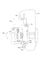
図1および図2は、本発明の第1実施形態に係わるブレ補正装置を具備したカメラ101の機能構成を示す概略図である。図1はカメラ101を上面から見た場合の図であり、図2はカメラ101を側面から見た場合の図である。カメラ101に搭載されるブレ補正装置は、装置の振れを検出して像ブレ補正を行う。矢印103p、103yで示す振れは、光軸102に対してそれぞれ直交する2つの軸回りの振れ(以下、角度振れという)を表す。「p」はピッチ方向を意味し、「y」はヨー方向を意味する。また矢印104p、104yで示す振れは、光軸102に対してそれぞれ直交する方向の振れ(以下、平行振れという)を表す。
[First Embodiment]
FIG. 1 and FIG. 2 are schematic views showing the functional configuration of a
カメラ101はレリーズボタン105を備え、カメラCPU(中央演算処理装置)106はレリーズボタン105の操作信号S1を取得して撮像動作の制御を行う制御中枢部である。撮像素子107は撮像光学系を通して被写体を撮像し、撮像信号を出力する。
The
角速度計108p、108yは、矢印108pa、108yaでそれぞれ示す方向の角度振れを検出する第1振れ検出手段である。また、加速度計109p、109yは、矢印109pa、109yaでそれぞれ示す方向の平行振れを検出する第2振れ検出手段である。角速度計108p、108y、および加速度計109p、109yの各出力は、カメラCPU106に入力される。振れ補正部110は、振れ補正レンズ111を図1、図2の矢印110p、110yの方向に駆動することにより、角度振れと平行振れの両方を加味した振れ補正を行う。カメラCPU106は駆動部112に制御信号を出力し、駆動部112は振れ補正部110を駆動する。
The
本実施形態では、振れ補正手段として、算出された補正量に基づいて振れ補正レンズ111を光軸に垂直な面内で移動させる、いわゆる光学的な像ブレ補正が行われる。このようなレンズ駆動による方法に限らず、撮像素子107を光軸に垂直な面内で移動させることで像ブレ補正を行う方法がある。あるいは、撮像素子107が出力する各撮影フレームの画像の切り出し位置を変更することで、画像処理によって振れの影響を軽減させる電子的な像ブレ補正方法がある。いずれかの方法、またはそれらを組み合わせた方法により像ブレ補正を行うことでも本発明の目的を達成可能である。
In the present embodiment, so-called optical image blur correction, in which the
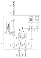
次に、図3を参照して本実施形態に係わるブレ補正装置の構成を説明する。図3は、ブレ補正装置を例示する機能ブロック図である。図3では、カメラ101の鉛直方向に生じる振れ(ピッチ方向:図2の矢印103p、104p参照)の構成のみを示している。同様の構成はカメラ101の水平方向に生じる振れ(ヨー方向:図1の矢印103y、104y参照)に対しても設けられている。これらは方向の違いを除いて基本的に同じ構成であるので、以下では、ピッチ方向の構成のみを図示して説明する。
Next, the configuration of the shake correction apparatus according to the present embodiment will be described with reference to FIG. FIG. 3 is a functional block diagram illustrating the blur correction apparatus. FIG. 3 shows only the configuration of shake (pitch direction: see
まず、角度振れ量の算出処理について説明する。角速度計108pの出力する角速度検出信号はカメラCPU106に入力される。角速度検出信号はHPF積分フィルタ301に入力される。HPF積分フィルタ301はHPF(ハイパスフィルタ)と積分フィルタを備える。HPF積分フィルタ301にてHPFは入力信号のDC(直流)成分をカットし、ハイパスフィルタ処理後の信号を積分フィルタが積分することで、角速度検出信号を角度信号に変換する。手振れの周波数帯域は1Hz〜10Hzの間である。そのため、HPFは、例えば手振れの周波数帯域から十分離れた0.1Hz以下の周波数成分をカットする1次のHPF特性を有する。HPF積分フィルタ301の出力は敏感度調整部303に入力される。
First, the calculation process of the angular shake amount will be described. The angular velocity detection signal output from the
敏感度調整部303は、ズーム及びフォーカス位置情報302と、それらにより求まる焦点距離と撮影倍率に基づいてHPF積分フィルタ301の出力を増幅することで、角度振れの補正目標値を出力する。ズーム及びフォーカス位置情報302は撮像光学系に設けられたズームレンズの位置検出部と、フォーカスレンズの位置検出部から取得される。敏感度調整部303を設ける理由は、ズームやフォーカス等に関する光学情報が変化することで振れ補正レンズ111の移動量に対するカメラ像面上での揺れ量の比である振れ補正敏感度に変化が生じるため、調整が必要であることによる。
HPF積分フィルタ301と敏感度調整部303とにより、角度振れ量の演算手段が構成される。
The
The
次に、平行振れ量の算出処理について説明する。本実施形態における平行振れ量は、以下の工程によって算出される。
(1)所定周波数に着目して算出した回転半径(Lと記す)と角速度計108pの出力から第1の平行振れ速度を算出する工程。
(2)第1の平行振れ速度と加速度計109pの出力する加速度検出信号から、第2の平行振れ速度を算出する工程。
(3)第2の平行振れ速度を積分処理して平行振れ変位を算出する工程。
(4)ズーム及びフォーカス位置情報302と、それらにより求まる撮影倍率に基づいて平行振れ変位を増幅し、平行振れの補正目標値を出力する工程。
Next, the parallel shake amount calculation process will be described. The parallel shake amount in the present embodiment is calculated by the following process.
(1) A step of calculating a first parallel shake speed from a rotation radius (referred to as L) calculated by paying attention to a predetermined frequency and an output of the
(2) A step of calculating a second parallel shake speed from the first parallel shake speed and the acceleration detection signal output from the
(3) A step of calculating the parallel shake displacement by integrating the second parallel shake speed.
(4) A process of amplifying the translational shake displacement based on the zoom and focus
回転半径Lと角速度計108pの出力より算出された第1の平行振れ速度から平行振れ補正を行う方法では、第1の平行振れ速度を全周波数帯域で精度良く算出することが難しい。このため、限定された特定の周波数帯域で補正効果の高い平行振れ速度を算出することが行われる。しかしながら、実際上ではカメラの手持ち撮影時の撮影条件においては、殆どの場合、複数の回転の影響により平行振れが発生する。つまり、回転半径Lを求めて角速度に回転半径Lを乗算して平行振れ量を算出する方法では、全ての周波数帯域において正しい振れ補正が行われるとは限らない。また、高周波帯域では実際の平行振れとは異なり、過補正により平行振れ補正の効果に影響を及ぼす可能性がある。
In the method of performing the parallel shake correction from the first parallel shake speed calculated from the rotation radius L and the output of the
また、平行振れ補正量に関する別の算出方法として、加速度センサの出力信号を2階積分して平行振れ変位を算出する方法がある。この場合、加速度計109pからは、平行振れに伴う振動加速度に重力加速度が加わった加速度検出信号が出力される。平行振れ補正に必要な振動加速度の検出に対して、カメラの姿勢角度によって変化する重力加速度がノイズとして現れることになる。この重力加速度が低周波帯域で非常に大きな出力ノイズとなって、この信号が2階積分されてしまうと、低周波ノイズについても増幅される。このため、振動加速度による平行振れ変位を正しく検出することは難しい。
As another method for calculating the translational shake correction amount, there is a method of computing the translational shake displacement by second-order integration of the output signal of the acceleration sensor. In this case, the
そこで本実施形態では第1の平行振れ速度と加速度計109pの出力から、第2の平行振れ速度を算出する工程において、低周波帯域では第1の平行振れ速度に対する重み付け値を大きくし、高周波帯域は加速度計出力に対する重み付け値を大きくして合成する。これにより、高周波帯域でのノイズと低周波帯域でのノイズを低減しつつ、2つの信号を合成して平行振れ量を算出することで、広い周波数帯域で高精度に検出することができる。すなわち、本実施形態によれば、検出された角速度に回転半径Lを乗算して平行振れ量を算出する方法では除去が難しい高周波帯域でのノイズを除去可能である。また加速度計出力から平行振れ量を算出する方法では除去が難しい低周波帯域でのノイズを除去可能である。
Therefore, in the present embodiment, in the step of calculating the second parallel shake speed from the first parallel shake speed and the output of the
以下に、本実施形態に係る平行振れ速度および補正目標値について詳細な演算方法を説明する。
角速度計108pの出力する角速度検出信号は、HPF積分フィルタ301に入力されると共に、HPF309にも入力される。HPF309は入力信号のDC成分をカットして、出力補正部310に出力する。この処理と同時に、角速度計108pの出力する角速度検出信号はHPF位相調整部304に入力される。HPF位相調整部304は角速度計108pの出力に重畳されるDC成分をカットすると共に、その信号の位相調整を行う。HPF位相調整部304でのHPFのカットオフ周波数は、後述するHPF積分フィルタ305のHPFのカットオフ周波数と合わせてあり、周波数特性が一致するように設定されている。HPF位相調整部304の出力は角速度計BPF(バンドパスフィルタ)部306に入力され、ここで所定帯域の周波数成分のみが抽出される。
A detailed calculation method for the parallel shake speed and the correction target value according to the present embodiment will be described below.
The angular velocity detection signal output from the
一方、加速度計109pの出力はHPF積分フィルタ305に入力される。HPF積分フィルタ305にて、HPFが入力信号のDC成分をカットした後、積分フィルタが積分して加速度検出信号を速度信号に変換する。HPF積分フィルタ305のHPFのカットオフ周波数は、上述したようにHPF位相調整部304のHPFの周波数特性に合わせて設定されている。HPF積分フィルタ305の出力は加速度計BPF(バンドパスフィルタ)部307に入力され、ここで所定帯域の周波数成分のみが抽出される。
On the other hand, the output of the
比較部308は、角速度計BPF部306と加速度計BPF部307の各出力を取得し、回転半径Lを算出する。回転半径Lの算出は後述の方法で行われ、算出結果が出力補正部310に送られる。出力補正部310は、HPF309の出力であるHPF処理後の角速度検出信号と、比較部308から取得した回転半径Lを用いて第1の平行振れ速度を算出する。
The
次に、比較部308から出力補正部310へ出力される補正値(回転半径L)について説明する。
図4はカメラ101に加わる角度振れ103pと平行振れ104pを示した図である。カメラ101の撮影レンズ内にて撮像光学系の主点位置における平行振れをY(104p参照)と記し、角度振れをθ(103p参照)と記す。回転中心O(401p参照)を定めた場合の回転半径L(402p参照)とY、θの関係は、以下の(1)式で表される。また角速度をωと記し、速度をVと記すとV、L、ωの関係は、(2)式で表される。

FIG. 4 is a diagram showing the
(1)式では、加速度計109pの出力を2階積分して算出される変位Yと、角速度計108pを1階積分して算出される角度θとの比が回転半径Lである。また(2)式では、加速度計109pの出力を1階積分して算出される速度Vと、角速度計108pの出力である角速度ωとの比が回転半径Lである。(3)式では、加速度Aと角加速度ωaとの比が回転半径Lである。加速度計109pの出力により加速度Aが得られ、角速度計108pの出力を1階微分することより角加速度ωaが求まる。これらのいずれかの方法で回転半径Lを求めることができる。
In the equation (1), the radius of rotation L is the ratio between the displacement Y calculated by second-order integration of the output of the
比較部308は、例えば角速度計BPF部306の出力である角速度ωbと、加速度計BPF部307の出力を1階積分した速度Vbを取得して、以下の(4)式を用いて回転半径Lを算出する。
![]()
![]()
回転半径Lについては、所定時間内の速度Vbと角速度ωbのそれぞれの最大振幅のピーク値の比から算出することもできる。所定時間は、例えば、角速度計BPF部306および加速度計BPF部307のカットオフ周波数が5Hzの場合、200ms程度に設定される。更には、回転半径Lの更新に関して、速度Vbと加速度ωbがそれぞれ算出されるときに行ってもよい。あるいは、回転半径Lを算出する際の高周波ノイズ成分を除去するために、比較部308が速度Vbと角速度ωbをそれぞれ時系列的に平均化し、またはローパスフィルタ(LPF)で高周波成分をカットする処理を行ってもよい。
The rotation radius L can also be calculated from the ratio of the peak values of the maximum amplitudes of the velocity Vb and the angular velocity ωb within a predetermined time. For example, when the cut-off frequency of the angular velocity
出力補正部310は、比較部308が算出した回転半径Lと、HPF309の出力であるHPF処理後の角速度検出信号から、式(2)により第1の平行振れ速度を算出する。第1の平行振れ速度は速度算出部311に入力される。速度算出部311には同時に加速度計109pの出力が入力される。速度算出部311は、加速度計109pの出力する加速度検出信号と第1の平行振れ速度を取得して、第2の平行振れ量を算出する。
The
以下では、加速度検出信号と第1の平行振れ速度から、推定器の一例であるカルマンフィルタを用いて第2の平行振れ速度を算出する処理について説明する。
下式のように、状態変数を(Velocity:平行速度,Accelbias:加速度計のオフセットバイアス成分)とする。
![]()
As shown in the following equation, the state variables are (Velocity: parallel velocity, Accelbias: offset bias component of the accelerometer).
![]()
ここで、システムノイズの分散値を表す「Q=σw 2」と、観測ノイズの分散値を表す「R=σv 2」は、以下のように設定される。
システムノイズの分散Qについては、入力端に加わるシステムノイズである加速度計109pのセンサノイズから設定される。また観測ノイズの分散Rについては、出力補正部310の出力である第1の平行振れ速度に含まれるノイズから設定される。分散QとRの大きさに応じて、カルマンゲインgが変化する。分散Qの値を大きくしていくと第1の平行振れ速度の重み付け値を大きくするように第2の平行振れ速度(振れ補正速度)が算出される。また、分散Rの値を大きくしていくと加速度計109pの出力の重み付け値を大きくするように第2の平行振れ速度が算出される。速度算出部311はカメラ101の手持ち状態における撮影条件に合わせてQ値、R値を決定し、第2の平行振れ速度を算出する。
Here, “Q = σ w 2 ” representing the variance value of the system noise and “R = σ v 2 ” representing the variance value of the observation noise are set as follows.
The system noise variance Q is set from the sensor noise of the
また、カメラ101の振動状態を検出して、振動状態に合わせてカルマンゲインgを設定することもできる。例えば、振動が小さい場合、低周波の大きな平行振れ量ではなく、比較的高周波の小さな平行振れ量となる。そこで、振動が小さい場合は、カメラ姿勢の角度変化量が小さく、重力による影響の変化に起因する加速度計出力ノイズが比較的小さくなるので、分散Rの値が大きく設定される。つまり、加速度計109pの出力に対して重み付け値を相対的に大きくして第2の平行振れ速度が算出される。一方、振動が大きく、低周波の大きな平行振れが支配的である場合には、カメラ姿勢の角度変化量が大きく、重力による影響の変化に起因する加速度計出力ノイズが大きくなるので、分散Qの値が大きく設定される。つまり、第1の平行振れ速度の重み付け値を相対的に大きくして第2の平行振れ速度が算出されるので、加速度計の出力誤差による像ブレ補正への影響を低減できる。
It is also possible to detect the vibration state of the
カメラ101の振動状態の検出には、角速度計108pまたは加速度計109pの出力、或いはその両方の出力を用いることができる。振動状態検出部は、例えば角速度計108pの出力や加速度計109pの出力をHPFに通し、HPF処理後の信号を絶対値変換する。振動状態検出部は、絶対値変換後の信号が所定時間内で所定レベルの閾値を超えた回数を計測し、この回数を所定の閾値と比較する。計測された回数が所定の閾値以下である場合、揺れが小さい状態と判定され、また計測された回数が所定の閾値より大きい場合には揺れが大きい状態と判定される。あるいは、他の方法では、振動状態検出部が絶対値変換後の信号から移動平均やLPF等によって生成した信号のレベルを所定の閾値と比較する。信号レベルが所定の閾値以下である場合、揺れが小さい状態と判定され、また信号レベルが所定の閾値より大きい場合、揺れが大きい状態と判定される。
For detection of the vibration state of the
上記の処理によって、簡単な構成で、振動状態に合わせた最適な平行振れ速度を算出することができる。なお、一例としてカルマンフィルタを用いた第2の平行振れ速度の算出処理について説明したが、別の方法もある(図5参照)。例えば、出力補正部310の出力である第1の平行振れ速度に対してローパスフィルタ処理が行われる。LPF処理後の速度(LPF速度)は積分処理されて角度(LPF角度)が算出される。加速度計109pの出力に対してはハイパスフィルタ処理が行われる。HPF処理後の速度(HPF速度)は積分処理されて角度(HPF角度)が算出される。LPF角度とHPF角度を加算することで第2の平行振れ速度を算出することができる。図5は各フィルタの特性を例示する。上側に位相(Phase)特性を示し、下側に利得(Gain)特性を示しており、横軸は周波数軸である。この方法では、LPFのカットオフ周波数501とHPFのカットオフ周波数502は同じ値に設定される。低周波帯域では出力補正部310からの第1平行振れ速度に基づいて第2の平行振れ速度を算出し、高周波帯域では加速度計109pの出力に基づいて第2の平行振れ速度を算出することができる。この場合、角速度計108pまたは加速度計109pの出力、或いはその両方を用いて、前記と同様にカメラ101の振動状態が判定される。振動状態の判定結果にしたがって各フィルタのカットオフ周波数501,502が変更される。例えば、カメラ101の振動が閾値より大きい状態であると判定された場合、カットオフ周波数501,502が低い値に設定され、加速度計109pから算出される平行振れの比率が大きくなるように加算合成処理が行われる。またカメラ101の振動が閾値より小さい状態であると判定された場合、カットオフ周波数501,502が高い値に設定され、回転半径Lを用いて算出された第1の平行振れ速度の出力の比率が大きくなるように加算合成処理が行われる。こうすることでカメラ101の振動状態に合わせて最適な平行振れ速度を算出できる。
With the above processing, it is possible to calculate the optimum parallel shake speed according to the vibration state with a simple configuration. In addition, although the calculation process of the 2nd parallel shake speed using a Kalman filter was demonstrated as an example, there exists another method (refer FIG. 5). For example, the low-pass filter process is performed on the first parallel shake speed that is the output of the
図3の速度算出部311は、算出した第2の平行振れ速度を積分器312に出力する。積分器312は、積分処理によって平行振れ変位を算出し、敏感度調整部313に出力する。敏感度調整部313は、ズーム及びフォーカス位置情報302と、それらにより求まる撮影倍率に基づいて積分器312の出力を増幅し、平行振れの補正目標値を加算器314に出力する。加算器314は、敏感度調整部303の出力である角度振れの補正目標値と、敏感度調整部313の出力である平行振れの補正目標値を加算する。こうして、振れ補正目標値が算出され、駆動部112に出力される。
The
敏感度調整部303、敏感度調整部313、加算器314で演算される振れ補正目標値をδと記す。撮像光学系の焦点距離をfと記し、撮影倍率をβと記し、振れ補正敏感度をTsと記す。振れ補正敏感度Tsは、振れ補正部110の移動量に対するカメラ像面上での揺れ量の比である。振れ補正目標値δは、平行振れYおよび撮像光学系の振れ角度θと、撮像光学系の焦点距離fおよび撮影倍率βと、振れ補正敏感度Tsを用いて下式(12)により算出される。
![]()
![]()
(12)式の右辺第1項は敏感度調整部303の出力である角度振れ補正量であり、右辺第2項は敏感度調整部313の出力である平行振れ補正量である。こうして算出された、加算器314の出力である振れ補正目標値δは、駆動部112に入力される。振れ補正目標値δに基づいて駆動部112は振れ補正部110を駆動し、振れ補正レンズ111の移動により振れ補正動作が行われる。
The first term on the right side of equation (12) is the angular shake correction amount that is the output of the
本実施形態では、検出した角速度に回転半径Lを乗算することで第1の平行振れ速度が算出される。低周波帯域では第1の平行振れ速度に対する重み付け値を大きくし、高周波帯域では加速度出力から得られる平行振れ速度に対する重み付け値を大きくして信号を合成し、第2の平行振れ速度が算出される。第2の平行振れ速度の積分処理により平行振れ変位が算出され、敏感度調整後に平行振れの振れ補正目標値が得られる。本実施形態によれば、高周波帯域および低周波帯域での各ノイズ成分を除去しつつ、2つの信号を合成して平行振れ量を算出することで広い周波数帯域に亘って高精度に検出できるので、平行振れに対する像ブレ補正効果が向上する。 In the present embodiment, the first parallel shake velocity is calculated by multiplying the detected angular velocity by the rotation radius L. In the low frequency band, the weight value for the first parallel shake speed is increased, and in the high frequency band, the weight value for the parallel shake speed obtained from the acceleration output is increased to synthesize the signal, and the second parallel shake speed is calculated. . A translational shake displacement is calculated by integration processing of the second translational shake speed, and a translational shake correction target value for the translational shake is obtained after sensitivity adjustment. According to the present embodiment, it is possible to detect with high accuracy over a wide frequency band by calculating the parallel shake amount by combining two signals while removing each noise component in the high frequency band and the low frequency band. The image blur correction effect against parallel shake is improved.
[第2実施形態]
次に、本発明の第2実施形態を説明する。本実施形態にて第1実施形態の場合と同様の構成部については既に使用した符号を用いることにより、それらの詳細な説明を省略し、相違点を中心に説明する。このような説明の省略については後述の実施形態でも同じである。
[Second Embodiment]
Next, a second embodiment of the present invention will be described. In the present embodiment, the same components as those in the first embodiment are denoted by the same reference numerals as those used in the first embodiment, and detailed description thereof will be omitted, and differences will be mainly described. Omitting such description is the same in the embodiments described later.
図6を参照して、本実施形態に係るブレ補正装置を説明する。図6はブレ補正装置の制御ブロック図である。本実施形態の特徴は、以下の通りである。
・撮像された画像の動きベクトルを算出する動きベクトル算出部601が設けられていること。
・切り出し量調整部604および画像切り出し振れ補正部605が設けられていること。
With reference to FIG. 6, the shake correction apparatus according to the present embodiment will be described. FIG. 6 is a control block diagram of the shake correction apparatus. The features of this embodiment are as follows.
A motion
A cutout
本実施形態では、第1の平行振れ速度の検出手段である動きベクトル算出部601が、撮像素子107の出力する画像データから装置の振れを検出する。つまり、動きベクトル算出部601は、撮像素子107が異なる時刻に出力する画像同士を比較し、動きベクトルの算出処理を行う。動きベクトルを利用して手振れや構図のずれを検出する方法では、実際に撮像された画像データに基づいて振れを検出できる。検出された画像のずれを表す動きベクトルに基づいて、画像シフト量を求め、画像シフト量に合わせてフレーム画像の切り出し処理を行うことにより、動画撮影における像ブレ補正が可能である。その際には以下の事項に留意すべきである。
In the present embodiment, a motion
動きベクトルは、撮像されるフレーム画像ごとに検出されるので、フレームレートによっては、精度よく検出可能な周波数帯域が制限される場合がある。また、画像から被写体像のずれがベクトルで検出されるので、実際の像ブレに対する時間遅れを無視することができない。つまり低周波帯域での検出精度は高いが、高周波帯域での検出精度が低下する可能性がある。そこで本実施形態では、低周波帯域において、動きベクトルにより検出された振れ量に対する重み付け値を大きくし、高周波帯域において、加速度センサの出力に対する重み付け値を大きくする制御が行われる。重み付け値が制御された各信号を合成することにより振れ補正量が算出されるので、平行振れ量の検出精度を向上させることができる。 Since the motion vector is detected for each captured frame image, the frequency band that can be accurately detected may be limited depending on the frame rate. Further, since the deviation of the subject image from the image is detected by a vector, the time delay with respect to the actual image blur cannot be ignored. That is, the detection accuracy in the low frequency band is high, but the detection accuracy in the high frequency band may be lowered. Therefore, in this embodiment, control is performed to increase the weighting value for the shake amount detected by the motion vector in the low frequency band and increase the weighting value for the output of the acceleration sensor in the high frequency band. Since the shake correction amount is calculated by synthesizing the respective signals whose weight values are controlled, the detection accuracy of the parallel shake amount can be improved.
本実施形態では、動きベクトルを用いて平行振れ量を検出し、平行振れ補正にて電子式の切り出し画像を利用した像ブレ補正を行う。すなわち、切り出し量調整部604および画像切り出し振れ補正部605は光学部材を駆動するのではなく、画像処理によって像ブレを補正する。一方、角度振れ補正については第1実施形態の場合と同様に、振れ補正レンズ111の駆動による光学的な像ブレ補正が行われる。角速度計108pにより検出される振れ検出信号については、HPF積分フィルタ301がHPF処理および積分処理を行い、さらに敏感度調整部303が敏感度調整を行う。ズーム及びフォーカス位置情報302を用いて敏感度調整が行われた角度振れの補正目標値は駆動部112に入力され、振れ補正部110により角度振れ補正が行われる。
In this embodiment, the amount of parallel shake is detected using a motion vector, and image blur correction using an electronic cut-out image is performed by parallel shake correction. That is, the cutout
以下、動きベクトル算出部601が行う動きベクトル算出について具体的に説明する。
撮像素子107は、被写体からの反射光を電気信号に光電変換することで画像情報を取得する。取得された画像情報はデジタル信号に変換され、変換処理後のデジタル画像データは動きベクトル算出部601に送られる。この時点で動きベクトル算出部601は、あらかじめメモリに記憶されている1フレーム前の画像データを取得し、時間的に連続する過去の画像データと現在の画像データを比較する。動きベクトル算出部601は、異なる時刻の画像同士の相対的なズレ情報から動きベクトルを算出する。このときに抽出される画像情報としては、画像全体のデータ、または画像内の一部のデータである。または、動きベクトル算出部601は、画像内を複数の領域に分割した小領域にてそれぞれの画像データを比較することで動きベクトルを算出し、その中から最適な動きベクトルを選択する。動きベクトルの算出処理の方法については限定されない。
Hereinafter, the motion vector calculation performed by the motion
The
動きベクトル算出部601は、算出した動きベクトルの情報を速度算出部602に出力する。速度算出部602は取得した動きベクトルの情報と、加速度計109pの出力を用いて速度算出処理を実行する。まず速度算出部602は、動きベクトルを平行振れ速度量Vに変換する。動きベクトルの速度をVmと記し、1ピクセルあたりのピッチをPと記し、ズーム及びフォーカス位置情報302に基づく撮影倍率をβと記す。下記式(13)により、速度Vmから平行振れ速度量Vに変換される。
![]()
![]()
速度算出部602は、式(13)により得られる平行振れ速度量Vを第1の平行振れ速度として、第1実施形態の場合と同様に、式(5)乃至(11)を用いて第2の平行振れ速度を算出する。
The
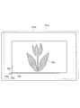
速度算出部602が出力する第2の平行振れ速度は、積分器603に入力される。積分器603は積分処理により平行振れ変位を算出し、平行振れ変位を切り出し量調整部604に出力する。切り出し量調整部604は、ズーム及びフォーカス位置情報302およびそれらにより求まる撮影倍率βに基づいて、画像切り出し位置を設定する。切り出し量調整部604が出力する画像切り出し位置の情報は、画像切り出し振れ補正部605に入力される。画像切り出し振れ補正部605は、取得した画像切り出し位置にしたがい、画像切り出しによる平行振れ補正を行う。図7を参照して、画像データの切り出し処理に基づく電子的な像ブレ補正を説明する。
The second translational shake speed output from the
図7は、画像切り出し振れ補正部605が画像シフト処理を行う様子を説明する図である。対象画像は、撮像素子107の出力から生成された撮像画像である。画像シフト処理では、撮像画像のうちの出力領域が変更される。例えば、図7の画像701aは、撮影時刻T1で撮影された撮像素子107の出力画像を示す。画像701bは、撮影時刻T1から所定時間の経過後(例えば1/30秒後)の撮影時刻T2で撮影された撮像素子107の出力画像を示す。
FIG. 7 is a diagram for explaining how the image cutout
撮影光軸を偏心させて像ブレを光学的に補正する振れ補正手段をもたない撮像装置の場合、2つの画像701aと701bとでは角度振れと平行振れに応じた位置ずれの影響を受ける。本実施形態では、駆動部112と振れ補正部110によって角度振れ補正が行われるので、平行振れの影響のみにより画像701aと701bとで構図にずれが発生する。切り出し量調整部604は、画像の水平方向と垂直方向のそれぞれの平行振れ量から、撮影フレームごとに水平方向と垂直方向のそれぞれの画像切り出し移動量を算出する。図7の矢印702yで示す第1のベクトルは、水平方向の画像切り出し移動量を表し、矢印702pで示す第2のベクトルは、垂直方向の画像切り出し移動量を表している。第1のベクトルと第2のベクトルを合成すると、矢印702で示すベクトル、つまり、画像切り出し移動量分に相当する合成ベクトルが得られる。
In the case of an imaging apparatus that does not have a shake correction unit that optically corrects an image blur by decentering a photographing optical axis, the two
画像切り出し振れ補正部605は、切り出し量調整部604から取得した画像切り出し移動量の情報を用いて、画像切り出し位置をシフトさせる。これにより、撮影時刻T1での画像701aにおける切り出し画像は画像703となり、撮影時刻T2での画像701bにおける切り出し画像も画像703となる。すなわち、主被写体704の画像の像ブレが抑制された状態で動画撮影が行われる。画像切り出し振れ補正部605は撮影フレームごとに画像切り出し処理による平行振れ補正を行う。こうして、動画撮影中に平行振れ補正と角度振れ補正とが同時に実行される。
The image cutout
本実施形態では、角度振れの補正処理部が角速度計108pの出力から角度振れ補正量を算出し、撮影光軸を偏心させることで像ブレを補正する。平行振れの補正処理部は、動きベクトルと加速度計109pの出力から平行振れ補正量を算出し、撮影画像の出力領域をシフトさせて画像切り出し処理により像ブレを補正する。本実施形態によれば、像ブレ補正を高精度に行うことができる。
In the present embodiment, the angular shake correction processing unit calculates the angular shake correction amount from the output of the
[第3実施形態]
次に本発明の第3実施形態を説明する。
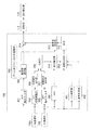
図8は、本実施形態に係るブレ補正装置の制御ブロック図である。第1実施形態の場合(図3参照)との相違点は、2つの判定部801および802が設けられている点である。判定部801はパンニング状態の判定(以下、パン判定ともいう)を行うパン判定部801である。また判定部802は、撮像装置の姿勢変化について判定を行う姿勢判定部である。パン判定部801と姿勢判定部802の各出力は、速度算出部803に入力される。本実施形態の特徴は、パン判定部801のパンニング判定結果と姿勢判定部802の姿勢判定結果に基づいて、速度算出部803が第1の平行振れ速度と加速度計109pの出力から得られる速度との合成比率を変更することである。
[Third Embodiment]
Next, a third embodiment of the present invention will be described.
FIG. 8 is a control block diagram of the shake correction apparatus according to the present embodiment. The difference from the case of the first embodiment (see FIG. 3) is that two
まず、パン判定部801が行うパンニング状態の判定処理を説明する。
パンニング判定処理において、パン判定部801は角速度計108pの出力を取得して、所定の閾値と比較する。角速度検出信号のレベルが所定の閾値以上である時間(検出時間)が計測される。検出時間が所定時間以上である場合、パン判定部801はパンニング操作中であると判定する。所定時間とは、パンニングの継続期間を判定するために予め設定される基準時間である。パン判定部801は、ユーザによるパンニング操作中であるかどうかを示すパンニング判定結果を速度算出部803に出力する。
First, the panning state determination process performed by the
In the panning determination process, the
パンニング時にはカメラの傾き角度が変化するので、加速度計109pの出力に重力が及ぼす影響による成分が重畳しやすくなる。また、パンニング時にはパンニング操作に伴う回転半径L(図4参照)が支配的であるため、平行速度の検出精度は高い。そのため、速度算出部803は、パンニング状態と判定された場合に加速度計109の出力に対する重み付け値を相対的に小さくし、第1の平行振れ速度に対する重み付け値を相対的に大きくするように合成比率を変更する。この合成比率を用いて演算される第2の平行振れ速度を使用して像ブレ補正が行われる結果、平行振れ補正効果が向上する。つまり、実際の平行振れに近い信号が生成され、この信号に基づいて平行振れ補正が行われる。なお、チルティング状態の判定についても同様の処理が行われる。この場合、チルト判定部は、チルティング状態と判定された場合に加速度計109の出力に対する重み付け値を相対的に小さくし、第1の平行振れ速度に対する重み付け値を相対的に大きくするように合成比率を変更する。
Since the tilt angle of the camera changes during panning, components due to the influence of gravity on the output of the
次に、姿勢判定部802が行う姿勢判定処理について説明する。
加速度計109に3軸加速度計を用いる場合、その出力は姿勢判定部802に入力され、姿勢判定部802はカメラの傾き角度を算出する。加速度計109の測定軸をX軸、Y軸、Z軸とし、X軸を撮像素子の撮像面内での水平方向の軸と定義する。またY軸を撮像素子の撮像面内での垂直方向の軸と定義し、Z軸をカメラの光軸方向の軸と定義する。つまりカメラは撮像面(X−Y平面)に直交するZ軸方向を向くように配置されており、各軸の加速度出力の関係から、カメラの傾き角度を算出することができる。カメラの姿勢変化によって重力加速度に及ぼす影響が異なることについて、図9を参照して説明する。
Next, posture determination processing performed by the
When a triaxial accelerometer is used as the
図9は、カメラ正位置での角度を0度とした場合の、カメラのロール角度変化による加速度計109の出力変化を例示する。カメラ正位置は、ユーザがカメラを横位置で構えているときに、撮像素子の左右方向の軸が重力方向と垂直となっている基準姿勢に相当する。図9の横軸は角度(単位:degree)を表し、縦軸は加速度計109の出力(単位:G)を表す。グラフ線901はX軸の出力変化を示し、グラフ線902はY軸の出力変化を示す。
FIG. 9 exemplifies a change in the output of the
カメラ正位置における角度が0度の付近では、ロール角度の変化に対するY軸での重力加速度の変化量は小さいが、X軸では0度の付近で傾きが大きいためロール角度の変化に対する重力加速度の変化量が大きくなる。従って、カメラ正位置付近において、Y軸での加速度計109の出力に対する重み付け値を大きくする制御が行われる。つまり第2の平行振れ速度を算出した場合の精度が高まる。しかし、X軸での加速度計109の出力に対する重み付け値を大きくしてしまうと、重力加速度の変化の影響によって第2の平行振れ速度の誤演算を招く可能性がある。よって、X軸での加速度計109の出力に対する重み付け値を小さくして、第2の平行振れ速度を算出する処理が行われる。また、カメラの縦位置、つまり角度が90度または−90度の姿勢においては、角度が0度の姿勢のときのX軸およびY軸での重力加速度の影響とは逆になる。よって、Y軸での加速度計109の出力に対する重み付け値を小さくし、X軸での加速度計109の出力の重み付け値を大きくして、第2の平行振れ速度が算出される。このようにカメラの姿勢変化に応じて合成比率を変更することで、カメラ姿勢に最も適した平行振れ補正量を算出することができる。
When the angle at the camera normal position is near 0 degrees, the amount of change in the gravitational acceleration on the Y axis with respect to the change in the roll angle is small, but on the X axis, the inclination is large near 0 degrees. The amount of change increases. Accordingly, control is performed to increase the weighting value for the output of the
合成比率の変更方法には、第1実施形態で説明したように、カルマンフィルタのカルマンゲインを変更することで合成比率を変更する方法がある。あるいは別の方法で第2の平行振れ速度を算出してもよい。例えば、速度算出部は、出力補正部310の出力である第1の平行振れ速度にLPF処理を施し、LPF処理された速度(LPF速度)を算出する。また速度算出部は、加速度計109pの出力にHPF処理を施した後で積分して、HPFおよび積分処理された速度(HPF速度)を算出する。LPF速度とHPF速度を加算することで第2の平行振れ速度を算出することができる。この方法において、同じカットオフ周波数に設定されたLPFおよびHPFについては、カメラ姿勢に応じてカットオフ周波数を変更することにより、第2の平行振れ速度を算出してもよい。
As described in the first embodiment, the synthesis ratio changing method includes a method of changing the synthesis ratio by changing the Kalman gain of the Kalman filter. Alternatively, the second parallel shake speed may be calculated by another method. For example, the speed calculation unit performs LPF processing on the first parallel shake speed that is the output of the
本実施形態では、パンニング(またはチルティング)判定結果や姿勢判定結果に基づいて、第1の平行振れ速度と加速度計109の出力から得られる平行振れ速度に対する合成比率を変更する処理が行われる。合成比率の値が適正に変更されて第2の平行振れ速度が算出され、平行振れ補正が行われるので、カメラの状態や姿勢に合わせて適正な像ブレ補正を実現できる。
In the present embodiment, based on the panning (or tilting) determination result and the posture determination result, a process of changing the composite ratio for the first parallel shake speed and the parallel shake speed obtained from the output of the
101 カメラ
106 CPU
107 撮像素子
110 振れ補正部
111 振れ補正レンズ
107
Claims (16)
前記振れの角速度検出信号および加速度検出信号を取得する取得手段と、
前記取得手段によって取得された前記角速度検出信号および加速度検出信号から第1の振れ量を演算し、前記加速度検出信号と前記第1の振れ量との合成処理を行って第2の振れ量を演算する演算手段と、
前記演算手段により算出された前記第2の振れ量を取得して前記振れ補正手段を制御する制御手段を備えることを特徴とするブレ補正装置。 A shake correction device that corrects image blur of an image that may occur due to shake in a direction orthogonal to the optical axis of the imaging optical system, using a shake correction unit,
An acquisition means for acquiring an angular velocity detection signal and an acceleration detection signal of the shake;
A first shake amount is calculated from the angular velocity detection signal and acceleration detection signal acquired by the acquisition means, and a second shake amount is calculated by performing a synthesis process of the acceleration detection signal and the first shake amount. Computing means for
A shake correction apparatus comprising: control means for acquiring the second shake amount calculated by the calculation means and controlling the shake correction means.
前記システムノイズの分散値を大きくすることにより前記第1の振れ量の速度に対する重み付け値を相対的に大きくする制御、または前記観測ノイズの分散値を大きくすることにより前記加速度検出信号から得られる速度に対する重み付け値を相対的に大きくする制御を行うことを特徴とする請求項3に記載のブレ補正装置。 The estimator is an estimator using a Kalman filter,
Control that relatively increases a weighting value for the speed of the first shake amount by increasing the variance value of the system noise, or a speed obtained from the acceleration detection signal by increasing the variance value of the observation noise The blur correction apparatus according to claim 3, wherein control is performed to relatively increase a weighting value for.
前記加速度検出信号に対してハイパスフィルタ処理および積分処理を行う第1の演算手段と、
前記第1の振れ量に対してローパスフィルタ処理を行う第2の演算手段を有し、
前記第1および第2の演算手段によるそれぞれの出力を加算して積分することで、前記第2の振れ量を演算することを特徴とする請求項1に記載のブレ補正装置。 The computing means is
First computing means for performing high-pass filter processing and integration processing on the acceleration detection signal;
A second computing means for performing low-pass filter processing on the first shake amount;
The shake correction apparatus according to claim 1, wherein the second shake amount is calculated by adding and integrating the outputs of the first and second calculation means.
前記撮像光学系を通して撮像される画像から算出される振れ検出信号と、前記振れの加速度検出信号を取得する取得手段と、
前記取得手段によって取得された前記振れ検出信号と前記加速度検出信号との合成処理を行って振れ量を演算する演算手段と、
前記演算手段により算出された前記振れ量を取得して前記振れ補正手段を制御する制御手段を備えることを特徴とするブレ補正装置。 A shake correction device that corrects image blur of an image that may occur due to shake in a direction orthogonal to the optical axis of the imaging optical system, using a shake correction unit,
An acquisition means for acquiring a shake detection signal calculated from an image captured through the imaging optical system, and an acceleration detection signal of the shake;
A calculation means for calculating a shake amount by combining the shake detection signal acquired by the acquisition means and the acceleration detection signal;
A shake correction apparatus comprising: a control unit that acquires the shake amount calculated by the calculation unit and controls the shake correction unit.
前記演算手段は前記合成処理にて、第1の周波数帯域では前記動きベクトルから検出された振れ量に対する重み付け値を相対的に大きくし、前記第1の周波数帯域よりも高い第2の周波数帯域では前記加速度検出信号に対する重み付け値を相対的に大きくすることを特徴とする請求項9または10に記載のブレ補正装置。 The acquisition means acquires, as the shake detection signal, a motion vector calculated from a plurality of the images having different shooting times,
In the synthesis process, the arithmetic means relatively increases the weighting value for the shake amount detected from the motion vector in the first frequency band, and in the second frequency band higher than the first frequency band. The shake correction apparatus according to claim 9 or 10, wherein a weighting value for the acceleration detection signal is relatively increased.
前記撮像光学系を通して被写体を撮像する撮像手段と、
前記振れの角速度を検出して角速度検出信号を出力する第1の検出手段と、
前記振れの加速度を検出して加速度検出信号を出力する第2の検出手段を備えることを特徴とする撮像装置。 The blur correction device according to any one of claims 1 to 8,
Imaging means for imaging a subject through the imaging optical system;
First detection means for detecting an angular velocity of the shake and outputting an angular velocity detection signal;
An image pickup apparatus comprising: second detection means for detecting an acceleration of the shake and outputting an acceleration detection signal.
前記撮像光学系を通して被写体を撮像する撮像手段と、
前記振れの加速度を検出して加速度検出信号を出力する検出手段を備え、
前記取得手段は、前記撮像手段により得られる画像から算出される前記振れ検出信号と、前記検出手段の出力する加速度検出信号を取得することを特徴とする撮像装置。 The blur correction device according to any one of claims 9 to 11,
Imaging means for imaging a subject through the imaging optical system;
Detecting means for detecting acceleration of the shake and outputting an acceleration detection signal;
The imaging device is characterized in that the acquisition unit acquires the shake detection signal calculated from an image obtained by the imaging unit and an acceleration detection signal output from the detection unit.
前記振れの角速度検出信号および加速度検出信号を取得する取得工程と、
前記取得工程で取得された前記角速度検出信号および加速度検出信号から第1の振れ量を演算し、前記加速度検出信号と前記第1の振れ量との合成処理を行って第2の振れ量を演算する演算工程と、
前記演算工程で算出された前記第2の振れ量を取得して前記振れ補正手段を制御する制御工程を有することを特徴とするブレ補正方法。 A shake correction method executed by a shake correction device that corrects image blur of an image that may be caused by shake in a direction orthogonal to the optical axis of the imaging optical system, using a shake correction unit,
An acquisition step of acquiring an angular velocity detection signal and an acceleration detection signal of the shake;
A first shake amount is calculated from the angular velocity detection signal and the acceleration detection signal acquired in the acquisition step, and a second shake amount is calculated by performing a synthesis process of the acceleration detection signal and the first shake amount. An arithmetic process to perform,
A shake correction method comprising: a control step of acquiring the second shake amount calculated in the calculation step and controlling the shake correction means.
前記撮像光学系を通して撮像される画像から算出される振れ検出信号と、前記振れの加速度検出信号を取得する取得工程と、
前記取得工程で取得された前記振れ検出信号と前記加速度検出信号との合成処理を行って振れ量を演算する演算工程と、
前記演算工程で算出された前記振れ量を取得して前記振れ補正手段を制御する制御工程を有することを特徴とするブレ補正方法。 An image blur correction method executed by a blur correction device that corrects an image blur of an image that may be caused by a shake in a direction orthogonal to an optical axis of an imaging optical system,
An acquisition step of acquiring a shake detection signal calculated from an image captured through the imaging optical system, and an acceleration detection signal of the shake;
A calculation step of calculating a shake amount by performing a synthesis process of the shake detection signal and the acceleration detection signal acquired in the acquisition step;
A shake correction method comprising: a control step of controlling the shake correction means by acquiring the shake amount calculated in the calculation step.
Priority Applications (6)
| Application Number | Priority Date | Filing Date | Title |
|---|---|---|---|
| JP2015109363A JP6614810B2 (en) | 2015-05-29 | 2015-05-29 | Blur correction device, imaging device, and blur correction method |
| EP16802750.6A EP3304194A4 (en) | 2015-05-29 | 2016-05-10 | Shake correction device, image pickup apparatus, and shake correction method |
| KR1020177032191A KR102036084B1 (en) | 2015-05-29 | 2016-05-10 | Image stabilizer, image pickup device, and image stabilization method |
| CN201680028806.9A CN107615159B (en) | 2015-05-29 | 2016-05-10 | Shake correction device, imaging apparatus, and shake correction method |
| PCT/JP2016/002294 WO2016194307A1 (en) | 2015-05-29 | 2016-05-10 | Shake correction device, image pickup apparatus, and shake correction method |
| US15/571,106 US10222679B2 (en) | 2015-05-29 | 2016-05-10 | Shake correction device, image pickup apparatus, and shake correction method |
Applications Claiming Priority (1)
| Application Number | Priority Date | Filing Date | Title |
|---|---|---|---|
| JP2015109363A JP6614810B2 (en) | 2015-05-29 | 2015-05-29 | Blur correction device, imaging device, and blur correction method |
Publications (3)
| Publication Number | Publication Date |
|---|---|
| JP2016224204A true JP2016224204A (en) | 2016-12-28 |
| JP2016224204A5 JP2016224204A5 (en) | 2018-06-28 |
| JP6614810B2 JP6614810B2 (en) | 2019-12-04 |
Family
ID=57440806
Family Applications (1)
| Application Number | Title | Priority Date | Filing Date |
|---|---|---|---|
| JP2015109363A Active JP6614810B2 (en) | 2015-05-29 | 2015-05-29 | Blur correction device, imaging device, and blur correction method |
Country Status (6)
| Country | Link |
|---|---|
| US (1) | US10222679B2 (en) |
| EP (1) | EP3304194A4 (en) |
| JP (1) | JP6614810B2 (en) |
| KR (1) | KR102036084B1 (en) |
| CN (1) | CN107615159B (en) |
| WO (1) | WO2016194307A1 (en) |
Cited By (1)
| Publication number | Priority date | Publication date | Assignee | Title |
|---|---|---|---|---|
| JP2018112572A (en) * | 2017-01-06 | 2018-07-19 | 多摩川精機株式会社 | Photographing device |
Families Citing this family (15)
| Publication number | Priority date | Publication date | Assignee | Title |
|---|---|---|---|---|
| WO2013121366A1 (en) | 2012-02-15 | 2013-08-22 | Primesense Ltd. | Scanning depth engine |
| WO2017066778A1 (en) * | 2015-10-16 | 2017-04-20 | Tribune Broadcasting Company, Llc | Video-production system with dve feature |
| JP6990985B2 (en) * | 2017-04-25 | 2022-01-12 | キヤノン株式会社 | Image shake correction device and method, image pickup device and image pickup system |
| JP7071099B2 (en) * | 2017-11-22 | 2022-05-18 | キヤノン株式会社 | Imaging device |
| US11914220B2 (en) | 2018-05-21 | 2024-02-27 | Corning Incorporated | Liquid lens control systems and methods with reduced phase delay |
| WO2020042021A1 (en) | 2018-08-29 | 2020-03-05 | 深圳市大疆创新科技有限公司 | Control method and apparatus for electronic device, electronic device, and storage medium |
| US11178392B2 (en) * | 2018-09-12 | 2021-11-16 | Apple Inc. | Integrated optical emitters and applications thereof |
| CN113170038B (en) * | 2018-11-29 | 2023-06-13 | 富士胶片株式会社 | Jitter correction control device, method for operating jitter correction control device, storage medium, and image pickup device |
| JP7091474B2 (en) * | 2018-11-29 | 2022-06-27 | 富士フイルム株式会社 | Blur correction control device, operation method of blur correction control device, operation program of blur correction control device, and image pickup device |
| JP7208822B2 (en) * | 2019-02-22 | 2023-01-19 | キヤノン株式会社 | IMAGING DEVICE AND CONTROL METHOD THEREOF, PROGRAM, STORAGE MEDIUM |
| JP7233260B2 (en) * | 2019-03-13 | 2023-03-06 | キヤノン株式会社 | Image blur correction control device and its control method, program, storage medium |
| CN110290323B (en) * | 2019-06-28 | 2021-09-07 | Oppo广东移动通信有限公司 | Image processing method, image processing device, electronic equipment and computer readable storage medium |
| US11555982B1 (en) | 2020-12-15 | 2023-01-17 | Apple Inc. | Detecting positional deviations in an optical module |
| CN113329170B (en) * | 2021-05-10 | 2022-10-21 | 浙江大华技术股份有限公司 | Image shake correction method, image shake correction apparatus, computer device, and readable storage medium |
| CN113295256B (en) * | 2021-06-21 | 2022-05-24 | 锐马(福建)电气制造有限公司 | Method for eliminating shaking of hook scale |
Citations (14)
| Publication number | Priority date | Publication date | Assignee | Title |
|---|---|---|---|---|
| JP2007288726A (en) * | 2006-04-20 | 2007-11-01 | Matsushita Electric Ind Co Ltd | Imaging apparatus |
| JP2009118135A (en) * | 2007-11-06 | 2009-05-28 | Sony Corp | Imaging apparatus and imaging method |
| JP2010025961A (en) * | 2008-07-15 | 2010-02-04 | Canon Inc | Image stabilization control apparatus and image capturing apparatus |
| JP2010096938A (en) * | 2008-10-16 | 2010-04-30 | Canon Inc | Optical apparatus having image-blur correcting function and control method therefor |
| JP2011259314A (en) * | 2010-06-10 | 2011-12-22 | Fujifilm Corp | Imaging device, image processing device, and program |
| US20130162847A1 (en) * | 2011-12-21 | 2013-06-27 | Canon Kabushiki Kaisha | Image stabilization apparatus, control method therefor, optical apparatus and image capturing apparatus |
| US20130163084A1 (en) * | 2011-12-22 | 2013-06-27 | Canon Kabushiki Kaisha | Image stabilization apparatus, control method thereof, optical apparatus and image capturing apparatus |
| WO2014020924A1 (en) * | 2012-07-31 | 2014-02-06 | オリンパス株式会社 | Shake amount detection device, imaging device and shake amount detection method |
| JP2014041230A (en) * | 2012-08-22 | 2014-03-06 | Canon Inc | Optical device having image blur correction function and control method of the same |
| US20140085494A1 (en) * | 2012-07-24 | 2014-03-27 | Olympus Corporation | Amount-of-shake sensing apparatus, imaging apparatus, and method of detecting the amount of shake |
| US8736690B2 (en) * | 2011-04-12 | 2014-05-27 | Fujifilm Corporation | Image pickup apparatus |
| WO2014132827A1 (en) * | 2013-02-28 | 2014-09-04 | オリンパス株式会社 | Shake amount detection device and imaging device |
| US20140327789A1 (en) * | 2012-01-19 | 2014-11-06 | Olympus Corporation | Shaking amount detecting apparatus, image pickup apparatus, and shaking amount detecting method |
| JP2016024235A (en) * | 2014-07-16 | 2016-02-08 | キヤノン株式会社 | Imaging apparatus and control method thereof |
Family Cites Families (6)
| Publication number | Priority date | Publication date | Assignee | Title |
|---|---|---|---|---|
| JP3513950B2 (en) | 1993-12-14 | 2004-03-31 | 株式会社ニコン | Image stabilization camera |
| US5978600A (en) * | 1997-09-30 | 1999-11-02 | Nikon Corporation | Motion compensation device to compensate for motion of an optical system without using motion sensors |
| JP5094606B2 (en) | 2008-07-15 | 2012-12-12 | キヤノン株式会社 | Image shake correction apparatus, optical apparatus including the same, image pickup apparatus, and image shake correction apparatus control method |
| JP5181001B2 (en) * | 2010-08-09 | 2013-04-10 | キヤノン株式会社 | Image blur correction apparatus, control method therefor, and imaging apparatus and optical apparatus equipped with the image blur correction apparatus |
| JP5121911B2 (en) * | 2010-10-19 | 2013-01-16 | キヤノン株式会社 | Anti-shake control device, imaging device, and anti-shake control method |
| JP5846927B2 (en) * | 2012-01-19 | 2016-01-20 | オリンパス株式会社 | Blur amount detection device, imaging device, and blur amount detection method |
-
2015
- 2015-05-29 JP JP2015109363A patent/JP6614810B2/en active Active
-
2016
- 2016-05-10 KR KR1020177032191A patent/KR102036084B1/en active IP Right Grant
- 2016-05-10 CN CN201680028806.9A patent/CN107615159B/en active Active
- 2016-05-10 EP EP16802750.6A patent/EP3304194A4/en not_active Withdrawn
- 2016-05-10 US US15/571,106 patent/US10222679B2/en active Active
- 2016-05-10 WO PCT/JP2016/002294 patent/WO2016194307A1/en active Application Filing
Patent Citations (14)
| Publication number | Priority date | Publication date | Assignee | Title |
|---|---|---|---|---|
| JP2007288726A (en) * | 2006-04-20 | 2007-11-01 | Matsushita Electric Ind Co Ltd | Imaging apparatus |
| JP2009118135A (en) * | 2007-11-06 | 2009-05-28 | Sony Corp | Imaging apparatus and imaging method |
| JP2010025961A (en) * | 2008-07-15 | 2010-02-04 | Canon Inc | Image stabilization control apparatus and image capturing apparatus |
| JP2010096938A (en) * | 2008-10-16 | 2010-04-30 | Canon Inc | Optical apparatus having image-blur correcting function and control method therefor |
| JP2011259314A (en) * | 2010-06-10 | 2011-12-22 | Fujifilm Corp | Imaging device, image processing device, and program |
| US8736690B2 (en) * | 2011-04-12 | 2014-05-27 | Fujifilm Corporation | Image pickup apparatus |
| US20130162847A1 (en) * | 2011-12-21 | 2013-06-27 | Canon Kabushiki Kaisha | Image stabilization apparatus, control method therefor, optical apparatus and image capturing apparatus |
| US20130163084A1 (en) * | 2011-12-22 | 2013-06-27 | Canon Kabushiki Kaisha | Image stabilization apparatus, control method thereof, optical apparatus and image capturing apparatus |
| US20140327789A1 (en) * | 2012-01-19 | 2014-11-06 | Olympus Corporation | Shaking amount detecting apparatus, image pickup apparatus, and shaking amount detecting method |
| US20140085494A1 (en) * | 2012-07-24 | 2014-03-27 | Olympus Corporation | Amount-of-shake sensing apparatus, imaging apparatus, and method of detecting the amount of shake |
| WO2014020924A1 (en) * | 2012-07-31 | 2014-02-06 | オリンパス株式会社 | Shake amount detection device, imaging device and shake amount detection method |
| JP2014041230A (en) * | 2012-08-22 | 2014-03-06 | Canon Inc | Optical device having image blur correction function and control method of the same |
| WO2014132827A1 (en) * | 2013-02-28 | 2014-09-04 | オリンパス株式会社 | Shake amount detection device and imaging device |
| JP2016024235A (en) * | 2014-07-16 | 2016-02-08 | キヤノン株式会社 | Imaging apparatus and control method thereof |
Cited By (1)
| Publication number | Priority date | Publication date | Assignee | Title |
|---|---|---|---|---|
| JP2018112572A (en) * | 2017-01-06 | 2018-07-19 | 多摩川精機株式会社 | Photographing device |
Also Published As
| Publication number | Publication date |
|---|---|
| CN107615159B (en) | 2020-06-12 |
| JP6614810B2 (en) | 2019-12-04 |
| EP3304194A4 (en) | 2019-01-02 |
| KR20170134694A (en) | 2017-12-06 |
| US20180173079A1 (en) | 2018-06-21 |
| KR102036084B1 (en) | 2019-10-24 |
| EP3304194A1 (en) | 2018-04-11 |
| US10222679B2 (en) | 2019-03-05 |
| WO2016194307A1 (en) | 2016-12-08 |
| CN107615159A (en) | 2018-01-19 |
Similar Documents
| Publication | Publication Date | Title |
|---|---|---|
| JP6614810B2 (en) | Blur correction device, imaging device, and blur correction method | |
| KR101711807B1 (en) | Image stabilization apparatus, control method therefor, optical apparatus and imaging apparatus | |
| JP5181001B2 (en) | Image blur correction apparatus, control method therefor, and imaging apparatus and optical apparatus equipped with the image blur correction apparatus | |
| JP5111306B2 (en) | Optical apparatus having image blur correction function and control method thereof | |
| JP5121911B2 (en) | Anti-shake control device, imaging device, and anti-shake control method | |
| CN107257429B (en) | Image shake correction apparatus, control method, optical apparatus, and image pickup apparatus | |
| US9568742B2 (en) | Image stabilization apparatus, control method thereof, optical apparatus and image capturing apparatus | |
| JP6362556B2 (en) | Control device, imaging device, control method, program, and storage medium | |
| JP5414405B2 (en) | Image processing apparatus, imaging apparatus, and image processing method | |
| JP6105880B2 (en) | Imaging apparatus and control method thereof | |
| US8743221B2 (en) | Image capture apparatus and control method thereof | |
| JP5631063B2 (en) | Tilt detection device, shake correction device, imaging device, and tilt detection method thereof | |
| JP6659126B2 (en) | Image blur correction device, image blur correction method, imaging device, and program | |
| JP2014191017A (en) | Imaging device and method for controlling the same | |
| JP6024031B2 (en) | Blur correction device and optical apparatus | |
| JP5984467B2 (en) | Image blur correction device, optical apparatus, imaging device, and image blur correction device control method | |
| JP6448709B2 (en) | Image shake correction apparatus, image shake correction method, imaging apparatus, and optical apparatus | |
| JP2023035381A (en) | Image blur correction device, imaging system, camera body, method for controlling image blur correction device, and program | |
| JP2015028547A (en) | Imaging apparatus | |
| JP2012123261A (en) | Vibration isolation controlling device |
Legal Events
| Date | Code | Title | Description |
|---|---|---|---|
| A521 | Request for written amendment filed |
Free format text: JAPANESE INTERMEDIATE CODE: A523 Effective date: 20180516 |
|
| A621 | Written request for application examination |
Free format text: JAPANESE INTERMEDIATE CODE: A621 Effective date: 20180516 |
|
| A131 | Notification of reasons for refusal |
Free format text: JAPANESE INTERMEDIATE CODE: A131 Effective date: 20190514 |
|
| A521 | Request for written amendment filed |
Free format text: JAPANESE INTERMEDIATE CODE: A523 Effective date: 20190711 |
|
| TRDD | Decision of grant or rejection written | ||
| A01 | Written decision to grant a patent or to grant a registration (utility model) |
Free format text: JAPANESE INTERMEDIATE CODE: A01 Effective date: 20191008 |
|
| A61 | First payment of annual fees (during grant procedure) |
Free format text: JAPANESE INTERMEDIATE CODE: A61 Effective date: 20191105 |
|
| R151 | Written notification of patent or utility model registration |
Ref document number: 6614810 Country of ref document: JP Free format text: JAPANESE INTERMEDIATE CODE: R151 |