JP2016220604A - Portable engine-driven working machine - Google Patents
Portable engine-driven working machine Download PDFInfo
- Publication number
- JP2016220604A JP2016220604A JP2015109785A JP2015109785A JP2016220604A JP 2016220604 A JP2016220604 A JP 2016220604A JP 2015109785 A JP2015109785 A JP 2015109785A JP 2015109785 A JP2015109785 A JP 2015109785A JP 2016220604 A JP2016220604 A JP 2016220604A
- Authority
- JP
- Japan
- Prior art keywords
- engine
- control unit
- maintenance
- unit
- work machine
- Prior art date
- Legal status (The legal status is an assumption and is not a legal conclusion. Google has not performed a legal analysis and makes no representation as to the accuracy of the status listed.)
- Pending
Links
Images


Abstract
Description
本発明は、メンテナンス告知機能を有する携帯型エンジン駆動作業機に関するものである。 The present invention relates to a portable engine-driven work machine having a maintenance notification function.
搭載した小型エンジンの動力で作業部を駆動する携帯型の作業機(携帯型エンジン駆動作業機)は、刈り払い機、チェンソー、ヘッジトリマー、ブロア、噴霧機など、各種の作業機が知られている。 Portable work machines that drive the working part with the power of the small engine installed (portable engine-driven work machines) are known for various types of work machines such as brush cutters, chain saws, hedge trimmers, blowers, and sprayers. Yes.
このような携帯型エンジン駆動作業機の中には、エンジンの動作を電子制御するものが知られている。携帯型エンジン駆動作業機は、リコイルスタータの操作やエンジンの駆動によって発電する発電器(発電コイル)を備え、この発電器からの給電によって動作する制御ユニットを備えている(下記特許文献1参照)。
Among such portable engine-driven work machines, those that electronically control the operation of the engine are known. The portable engine-driven work machine includes a power generator (power generation coil) that generates electric power by operating a recoil starter or driving the engine, and includes a control unit that operates by feeding power from the power generator (see
携帯型エンジン駆動作業機における電子制御の一例は、エンジンの緊急停止であり、制御ユニットは、加速度センサなどの出力によって発生する停止信号によって、エンジンの点火を停止させたり、エンジン回転数の低下を検知して、エンジンの駆動力を作業部側に伝達する遠心クラッチの出力側クラッチドラムに電磁石ブレーキ機構による制動を加えたりする制御を行っている。 An example of electronic control in a portable engine-driven work machine is an emergency stop of the engine, and the control unit stops the ignition of the engine or reduces the engine speed by a stop signal generated by an output of an acceleration sensor or the like. Control is performed to detect and apply braking by the electromagnet brake mechanism to the output side clutch drum of the centrifugal clutch that transmits the driving force of the engine to the working unit side.
前述した制御ユニットを備える携帯型エンジン駆動作業機は、緊急時のエンジン停止によって安全性の高い作業を行うことが可能になる。この際、制御ユニットの出力によって動作するアクチュエータの中には、前述した電磁石ブレーキ機構のように、繰り返しの動作によって接触部が摩耗するなどして機能が低下するものがある。これに対しては、機能の低下を作業者が認識できれば、部品交換などのメンテナンスによって機能回復を図ることができるが、作業者が認識できる程に機能が低下してしまった後では、既に安全性の確保が難しくなっており、メンテナンス時期の把握が遅すぎる問題があった。また、明らかに機能が低下しているにも拘わらず作業者が気づかずに作業機を使用し続けることがあり、このような事態を回避するための対策が求められていた。 The portable engine-driven work machine including the control unit described above can perform highly safe work by stopping the engine in an emergency. At this time, among the actuators that are operated by the output of the control unit, there are some actuators whose functions are deteriorated, such as the above-described electromagnetic brake mechanism, because the contact portion is worn by repeated operations. In response to this, if the operator can recognize the deterioration of the function, the function can be recovered by maintenance such as replacement of parts. However, after the function has deteriorated to the extent that the operator can recognize it, it is already safe. There is a problem that it is difficult to ensure the safety and the maintenance time is too late. In addition, even though the function is clearly deteriorated, the worker may continue to use the work machine without noticing, and a countermeasure for avoiding such a situation has been demanded.
本発明は、このような問題に対処することを課題の一例とするものである。すなわち、エンジンを電子制御する制御ユニットを備えた携帯型エンジン駆動作業機において、制御ユニットの出力によって動作するアクチュエータの機能が低下する前に、作業者に対してメンテナンス時期を告知できるようにすること、明らかにアクチュエータの機能が低下しているにも拘わらず、作業者が気づかずに作業機を使用し続けることを回避すること、などが本発明の目的である。 This invention makes it an example of a subject to cope with such a problem. That is, in a portable engine-driven work machine equipped with a control unit that electronically controls the engine, the maintenance time can be notified to the operator before the function of the actuator that operates according to the output of the control unit deteriorates. Obviously, it is an object of the present invention to prevent the operator from continuing to use the working machine without realizing it even though the function of the actuator is obviously deteriorated.
このような目的を達成するために、本発明による携帯型エンジン駆動作業機は、以下の構成を具備するものである。
リコイルスタータの操作で始動するエンジンと、前記エンジンによって駆動される作業部と、前記エンジンの駆動又は前記リコイルスタータの操作によって発電する発電器からの給電で動作し、停止信号で前記エンジンを停止制御する制御ユニットとを備え、前記制御ユニットは、停止信号の動作回数をカウントして記憶する動作回数カウント部と、前記制御ユニットの動作開始時に、前記動作回数カウント部が記憶した動作回数を設定回数と比較してメンテナンス時期を判定するメンテナンス判定部と、前記メンテナンス判定部の判定結果によって、メンテナンスの必要性を告知する告知手段を動作させるメンテナンス告知部とを備えることを特徴とする携帯型エンジン駆動作業機。
In order to achieve such an object, a portable engine-driven work machine according to the present invention has the following configuration.
The engine is started by the operation of the recoil starter, the working unit driven by the engine, and the power generation from the generator driven by the engine or the operation of the recoil starter is operated, and the engine is stopped by a stop signal. A control unit that counts and stores the number of operations of the stop signal, and sets the number of operations stored by the operation count unit when the operation of the control unit starts. A portable engine drive comprising: a maintenance determination unit that determines a maintenance time compared to a maintenance determination unit; and a maintenance notification unit that operates a notification unit that notifies the necessity of maintenance based on a determination result of the maintenance determination unit Work machine.
本発明の携帯型エンジン駆動作業機は、このような特徴を有することで、停止時に制御ユニットの出力によって動作するアクチュエータの機能が低下する前に、作業者に対してメンテナンス時期を告知することができ、作業の安全性を確保することができる。また、明らかにアクチュエータの機能が低下しているにも拘わらず、作業者が気づかずに作業機を使用し続けることを回避することができる。 The portable engine-driven work machine of the present invention has such a feature, so that the maintenance time can be notified to the operator before the function of the actuator that operates according to the output of the control unit is lowered at the time of stoppage. It is possible to ensure work safety. Further, it is possible to prevent the operator from continuing to use the work implement without noticing it despite the fact that the function of the actuator is obviously lowered.
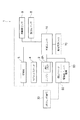
以下、図面を参照して本発明の実施形態を説明する。図1に示すように、本発明の実施形態に係る携帯型エンジン駆動作業機1は、リコイルスタータ4の操作で始動するエンジン2と、エンジン2によって駆動される作業部3と、エンジン2の駆動又はリコイルスタータ4の操作によって発電する発電器(発電コイル)5からの給電で動作し、例えば、緊急時の停止信号でエンジン2を停止制御する制御ユニット10とを備えている。
Hereinafter, embodiments of the present invention will be described with reference to the drawings. As shown in FIG. 1, a portable engine-driven
制御ユニット10は、停止信号によってエンジン2を停止制御するための機能として、停止信号によってエンジン2の点火プラグ2Aを失火モードにする点火制御部11と、作業部3の動作を停止させるアクチュエータ6を動作させるアクチュエータ動作部12を備えている。
The
また、制御ユニット10は、アクチュエータ6の動作回数をカウントして記憶する動作回数カウント部13と、制御ユニット10の動作開始時に、動作回数カウント部13が記憶した回数を設定回数と比較してメンテナンス時期を判定するメンテナンス判定部14と、メンテナンス判定部14の判定結果によって、メンテナンスの必要性を告知する告知手段7を動作させるメンテナンス告知部15とを備えている。また、制御ユニット10は、動作回数カウント部13が記憶した動作回数をリセットするカウントリセット部16を備えている。
In addition, the
図1において、破線は各部間の機械的な連結を示しており、実線は各部間の電気的な連結を示している。また、括弧内は制御ユニット10が備える回路又はプログラムによって実行される機能構成を示している。
In FIG. 1, broken lines indicate mechanical connections between the respective parts, and solid lines indicate electrical connections between the respective parts. The parentheses indicate the functional configuration executed by a circuit or program provided in the
携帯型エンジン駆動作業機1の制御ユニット10は、発電器5からの給電で動作するものであり、エンジン2の停止時には動作停止し、リコイルスタータ4の操作によって発電器5から給電がなされることで動作開始する。制御ユニット10の動作時(すなわち、エンジン駆動時)には、停止信号の発生によって点火制御部11が機能して点火プラグ2Aを失火モードにする。停止信号の発生は、各種の緊急停止装置からの入力などにより、例えば、作業者が操作するマニュアルスイッチからの入力や各種センサによる検知入力(加速度センサによる衝撃検知や回転数センサによる遠心クラッチオフ検知を含む)などによる。
The
制御ユニット10のアクチュエータ動作部12は、前述した停止信号によるエンジン2の停止に伴ってアクチュエータ6を動作させる機能であり、停止信号によって直接アクチュエータ6を動作させるか、或いは停止信号によるエンジン2の停止に付随してアクチュエータ6を動作させる。
The
制御ユニット10の動作回数カウント部13は、アクチュエータ6の動作回数を直接又は間接的にカウントするもので、停止信号の発生回数、アクチュエータ6を動作させる出力信号の発生回数などをカウントして、累計動作回数を記憶手段に記憶する。ここでの記憶手段は不揮発性メモリであり、動作回数カウント部13によるカウント後にエンジン2が停止して制御ユニット10が非動作状態になっても、記憶手段に記憶された累計の動作回数は保持される。
The
制御ユニット10のメンテナンス判定部14は、制御ユニット10の動作開始時に機能する。すなわち、メンテナンス判定部14は、エンジン2の停止状態からリコイルスタータ4の操作で制御ユニット10に発電器5からの給電がなされた直後に機能する。メンテナンス判定部14は、その時点で記憶手段に記憶されている動作回数カウント部13による累計の動作回数と予め設定値として記憶手段に記憶されている設定回数とを比較して、累計の動作回数が設定回数と等しい場合又は累計の動作回数が設定回数を超えた場合に、メンテナンス時期であるとの判定結果を出力する。ここでの設定回数は、繰り返し動作によって機能低下が生じるアクチュエータ6の耐用回数によって設定され、充分な安全性が確保されている回数が設定される。
The maintenance determination unit 14 of the
制御ユニット10のメンテナンス告知部15は、メンテナンス判定部14の判定結果により、メンテナンス時期であるとの判定がなされた場合に、告知手段7を動作させる。告知手段7は、作業者に対して視覚的、聴覚的又は触覚的にメンテナンスの必要性を告知できるものであればよく、例えば、光の点滅、ブザー音、ハンドルの振動などの発生手段を採用することができる。
The
制御ユニット10のカウントリセット部16は、アクチュエータ6に対して部品交換などのメンテナンスを完了した後に使用する機能であり、制御ユニット10に対して人為的な操作を加えることで、不揮発性メモリの記憶手段に記憶されている累計の動作回数をゼロにリセットする。
The
図2に、携帯型エンジン駆動作業機1のより具体的な構成例を示す。この例は、前述した作業部として刈り払い作業部30を備えており、エンジン2の駆動力を刈り払い作業部30側に伝達する遠心クラッチ20を備えている。また、前述したアクチュエータとして電磁石ブレーキ機構60を備え、停止信号の入力手段として、衝撃を検知する加速度センサ8とエンジン2の回転数を検知する回転数センサ9を備えている。そして、告知手段として、光の点滅によって作業者に告知する発光素子(LED)70を備えている。
FIG. 2 shows a more specific configuration example of the portable engine-driven
図2に示した携帯型エンジン駆動作業機1は、エンジン2の駆動時に加速度センサ8の出力によって緊急停止すべき衝撃が検知されると、停止信号が発生し、制御ユニット10の点火制御部11が機能して点火プラグ2Aを失火モードにする。また、点火制御部11によるエンジン2の停止制御により、エンジン回転数が低下すると、回転数センサ9がエンジン2の回転数を検知して、遠心クラッチ20が非伝動となる所定の回転数に達した時点で制御ユニット10のアクチュエータ動作部12が機能し、電磁石ブレーキ機構60を動作させる。電磁石ブレーキ機構60は、遠心クラッチ20の出力側クラッチドラムにコア(制動子)を吸着させ、刈り払い作業部30の慣性回転を停止させる。
The portable engine-driven
図3は、図2に示した構成例における制御ユニット10の動作フローを示している。エンジン2の停止状態からリコイルスタータ4を操作してエンジン2を始動させると、制御ユニット10が動作開始する(S1)。制御ユニット10は、先ず、カウントリセット部16が操作されているか否かをチェックし(S2)、カウントリセット部16が操作されている場合には(S2:YES)、LED70を特殊点灯パターンで表示し、記憶手段の動作回数カウントをゼロにリセットする(S3)。その後、点火制御部11を機能させ、点火プラグ2Aを失火モードにするエンジン停止制御を行う(S4)。
FIG. 3 shows an operation flow of the
制御ユニット10が動作開始して(S1)、カウントリセット部16が操作されていない場合には(S2:NO)、メンテナンス判定部14が機能する。この例では、メンテナンス判定部14は、設定回数として、第1設定回数(例えば3000回)と、第1設定回数より多い第2設定回数(例えば、5000回)とを備えており、メンテナンス告知部15は、メンテナンス判定部14の第1設定回数との比較による判定で第1段階の告知を行い、メンテナンス判定部14の第2設定回数との比較による判定で第2段階の告知を行う。
When the
具体的には、先ず、記憶手段に記憶されている動作回数が第2設定回数以下であるか否かが判定され(S5)、動作回数が第2設定回数を超えている場合は(S5:NO)、第2段階の告知としてLED70を高速点滅させ、その後失火モードによるエンジン停止制御を行う(S6)。動作回数が第2設定回数以下の場合には(S5:YES)、更に、記憶手段に記憶されている動作回数が第1設定回数以下であるか否かが判断される(S7)。そして、動作回数が第1設定回数を超えている場合は(S7:NO)、LED70を点滅(低速点滅)させることで、第1段階の告知を行う。
Specifically, first, it is determined whether or not the number of operations stored in the storage means is equal to or less than the second set number (S5). If the number of operations exceeds the second set number (S5: NO), the
第1段階の告知では、エンジン2を運転した状態で(S10:NO)、加速度センサ8による衝撃検知が無ければ(S11:NO)、エンジン2の駆動が継続される。そして、人為的又は燃料不足などでエンジン2が停止した場合には(S10:YES)、エンジン2の停止で制御ユニット10への給電が絶たれるので、制御ユニット10は動作終了する(S15)。
In the notification of the first stage, when the
エンジン2の駆動が継続されている状態で(S11:NO)、加速度センサ8の出力で衝撃検知がなされた場合には(S11:YES)、停止信号が発生して点火制御部11が機能し、失火モードによるエンジン停止制御が行われる(S12)。その後、エンジン2の回転数が低下して、回転数センサ9によって検出される回転数が設定回転数(例えば、3700rpm)以下になると(S13:YES)、アクチュエータ動作部12が機能して電磁石ブレーキ機構60が作動し、更に、動作回数カウント部13が機能して動作回数のカウント及び累計動作回数の記憶手段への記憶がなされ(S14)、エンジン2の停止と共に制御ユニット10の動作が終了する(S15)。
When the
このような制御ユニット10の動作フローによると、電磁石ブレーキ機構60の動作回数が増加して第1設定回数を超えると、リコイルスタータ4の操作によるエンジン始動時に、図3におけるS7のステップが「NO」の判定になり、LED70の点滅による第1段階の告知がなされる。作業者は、これによって電磁石ブレーキ機構60のメンテナンス時期を、電磁石ブレーキ機構60に顕著な機能低下が生じる前に認識することができる。
According to the operation flow of the
また、この第1段階の告知でメンテナンスを行わず、携帯型エンジン駆動作業機1を使用し続けた場合に、更に電磁石ブレーキ機構60の動作回数が増加して第2設定回数を超えると、リコイルスタータ4の操作によるエンジン始動時に、図3におけるS5のステップが「NO」の判定になり、LED70の高速点滅による第2段階の告知がなされる。そして、この第2段階の告知がなされた場合には、点火制御部11の失火モードによるエンジン停止制御が実行されることになり、継続的なエンジン2の駆動が阻止される。これにより、電磁石ブレーキ機構60がメンテナンスされることなく、携帯型エンジン駆動作業機1が引き続き使用される事態を回避することができる。
Further, when maintenance is not performed in this first stage notification and the portable engine
そして、第1段階の告知と第2段階の告知を2段階で行うことで、先ず第1段階の告知によって、メンテナンス時期を認識することができる。第1段階の告知から第2段階の告知までは安全性が確保された状態で、メンテナンス時期を念頭に置いた一定期間の使用が可能になる。 Then, by performing the first stage notification and the second stage notification in two stages, the maintenance time can be recognized first by the first stage notification. From the first stage notification to the second stage notification, safety can be ensured and it can be used for a certain period with the maintenance time in mind.
なお、図3に示した動作フローでは、第1設定回数と第2設定回数を設定する例を示しているが、第1設定回数のみでメンテナンス時期の判定を行い、その際に、図3のステップS6と同様に、点火制御部11の失火モードによるエンジン停止制御を行うようにしても良い。 In addition, although the example which sets the 1st setting frequency | count and the 2nd setting frequency | count is shown in the operation | movement flow shown in FIG. 3, determination of a maintenance time is performed only by the 1st setting frequency | count, In that case, FIG. Similarly to step S6, the engine stop control by the misfire mode of the ignition control unit 11 may be performed.
図4は、制御ユニット10を構成する具体的な制御回路例を示している。制御ユニット10には、発電用巻線50を備える発電器5の発電回路、電磁石ブレーキ機構60の駆動回路、発光素子70の駆動回路、加速度センサ8が図示のように接続されている。制御ユニット10は、加速度センサ8の入力回路、発光素子70の点灯出力回路、点火制御部11の失火出力回路、エンジンパルス入力回路、電磁石ブレーキ機構60の駆動回路などとして機能する主制御IC10Aと、カウントリセット部16を機能させるリセット用IC10Bを備えている。また、制御ユニット10は、加速度センサ8への印加電圧調整のためのレギュレータ10Dと、主制御ICの駆動電圧を設定するレギュレータ10Eを備えている。
FIG. 4 shows a specific control circuit example constituting the
主制御IC10Aは、I/Oポートを6ポート備えており、ポート1(図示GP0)が加速センサ8からの停止信号の入力ポート、ポート2(図示GP1)が発光素子70の点灯用出力ポート、ポート3(図示GP2)が点火制御部11への出力ポート、ポート4(図示GP3)がGNDポート、ポート5(図示GP4)がエンジンパルスの入力ポート、ポート6(図示GP5)が電磁石ブレーキ機構60の出力ポートにそれぞれなっている。リセット用IC10B,10Cは、P1,P2,P3の3ポートをそれぞれ備えており、P1が電源ポート、P2が出力ポート、P3がGNDポートになっている。
The
そして、この回路例では、制御ユニット10は、カウントリセット部16を動作させるためのリセット端子10Fを内部に備えている。リセット端子10Fは、端子間を接続した状態で発電器5からの給電がなされると、加速度センサ8からの停止信号がポート1(図示GP0)ポートに入力される毎に、動作回数カウント部13がカウントアップを行い、リセット端子10Fの端子間を図示のように非接続にした状態で発電器5からの給電がなされると、カウントリセット部16が動作して、累積カウントされた値をゼロにリセットする。
In this circuit example, the
具体的には、リセット用IC10B,10Cの動作は、電源ポートP1の入力が0V〜0.8V或いは4V以上のときに、出力ポートP2をHI(オープン)にし、電源ポートP1の入力が0.8V〜4Vのときに、出力ポートP2をLOW(GND)にする。これによって、リセット用IC10B,10Cは、発電器5の駆動によって入力されるエンジンの回転に伴うアナログ波形の入力信号を方形波形(パルス信号)に変換して出力する。
Specifically, the operation of the
リセット端子10Fの端子間が接続されている場合には、前述したように、リセット用IC10Bの出力ポートP2からエンジンの回転数に伴うアナログ波形を方形波形に変換したパルス信号が出力され、このパルス信号が主制御ICのポート5(図示GP4)に入力する。主制御ICは、入力されたパルス信号によって、エンジンの回転数を検知し、エンジンの回転数が検知されている状態では前述した動作回数カウント部13を動作させる。
When the terminals of the reset terminal 10F are connected, as described above, a pulse signal obtained by converting an analog waveform according to the engine speed into a square waveform is output from the output port P2 of the
これに対して、リセット端子10Fの端子間を非接続にすると、リセット用IC10Bの電源ポートP1への入力が0Vで変動しなくなるので、リセット用IC10Bの出力はHIのままになり、入力されるアナログ波形に対してリセット用IC10Bの出力ポートP2はパルス信号を出力しない。主制御IC10Aは、エンジン駆動によって発電器5から給電があるにも拘わらず、ポート5(図示GP4)にパルス信号が入力されないことを検知して、カウントリセット部16を動作し累積カウントのリセットを行うと共にリセット時特有の点滅パターンを実行した後、点火制御部11の失火制御を行ってエンジンを停止させる。なお、次の始動からは通常点火となる。
On the other hand, if the terminals of the reset terminal 10F are not connected, the input to the power supply port P1 of the
このように、制御ユニット10は、リセット端子10Fを非接続にすることでカウントリセット部16を動作させることができるので、メンテナンス終了後に、特別な機器を制御ユニット10に接続すること無く、カウントリセット部16を動作させることができる。
As described above, the
図5及び図6は、本発明の実施形態に係る携帯型エンジン駆動作業機1の一例である刈り払い機100を示している(図5が全体図であり、図6が駆動部の断面図、図6(a)が駆動部の全体を示し、図6(b)が遠心クラッチの構造を示している。)。刈り払い機100は、駆動部110と、駆動部100に一端が接続される操作チューブ101と、操作チューブ101の先端部に装備される刈り払い作業部30とを備えており、操作チューブ101に装着されているハンドル102を持って携帯作業を行うことができるものである。
5 and 6 show a
駆動部110には、小型のエンジン2が搭載されており、エンジン2はエンジンカバー111で被われている。エンジン2の下方には、燃料タンク112が装備されている。エンジン2の出力軸(クランクシャフト)2Bには、操作チューブ101が接続される一方の側に遠心クラッチ20が装着され、他方の側にリコイルスタータ4が装着されている。リコイルスタータ4は、リコイルケース113内に収められており、このリコイルケース113内に加速度センサ8や回転数センサ9を含む(図示省略)制御ユニット10が配置されている。
A
遠心クラッチ20は、クラッチカバー115内に装備されており、エンジン2の出力軸2Bと刈り払い作業部30の刈刃31に動力を伝達する伝動軸116とは、遠心クラッチ20を介して接続されている。クラッチカバー115内には、遠心クラッチ20のクラッチドラムに作用する電磁石ブレーキ機構60と、電磁石ブレーキ機構60を駆動するための電源となるコンデンサ114が配備されている。コンデンサ114には、エンジン2の駆動時に図示省略した発電器(発電コイル)で発電した電力が蓄電される。
The centrifugal clutch 20 is provided in the
このような刈り払い機100は、リコイルスタータ4を操作して、エンジン2を始動させ、ハンドル102に装備されたスロットルレバー103を操作しながら、エンジン2の駆動力で回転駆動される刈刃31で刈り払い作業を行う。この際、前述したように、リコイルスタータ4の操作によって制御ユニット10の動作が開始され、図3に示した動作フローが実行される。図5及び図6において図示省略した告知手段7(例えば、発光素子(LED)70)は、リコイルケース113の周辺に設けることが好ましい。これにより、作業者はリコイルスタータ4を操作した際に発光素子(LED)70の点滅状態を目にすることになり、電磁石ブレーキ機構60に対するメンテナンスの必要性をその点滅状態によって明確に把握することができる。
Such a
以上、本発明の実施の形態について図面を参照して詳述してきたが、具体的な構成はこれらの実施の形態に限られるものではなく、本発明の要旨を逸脱しない範囲の設計の変更等があっても本発明に含まれる。特に、実施形態では、電磁石ブレーキ機構60のメンテナンス時期告知を例にして説明しているが、これに限らず、制御ユニット10の出力で動作が繰り返されるアクチュエータであれば、同様にメンテナンス時期の告知とエンジンの停止制御を組み合わせた動作が可能である。
As described above, the embodiments of the present invention have been described in detail with reference to the drawings. However, the specific configuration is not limited to these embodiments, and the design can be changed without departing from the scope of the present invention. Is included in the present invention. In particular, in the embodiment, the maintenance time notification of the
1:携帯型エンジン駆動作業機,
2:エンジン,2A:点火プラグ,2B:出力軸(クランクシャフト),
3:作業部,4:リコイルスタータ,5:発電器,50:発電用巻線,
6:アクチュエータ,7:告知手段,8:加速度センサ,9:回転数センサ,
10:制御ユニット,10A:主制御IC,
10B,10C:リセット用IC,10D,10E:レギュレータ,
10F:リセット端子,
11:点火制御部,12:アクチュエータ動作部,
13:動作回数カウント部,14:メンテナンス判定部,
15:メンテナンス告知部,16:カウントリセット部,
20:遠心クラッチ,
30:刈り払い作業部,31:刈刃,
60:電磁石ブレーキ機構,70:発光素子(LED)
100:刈り払い機,101:操作チューブ,102:ハンドル,
103:スロットルレバー,110:駆動部,111:エンジンカバー,
112:燃料タンク,113:リコイルケース,114:コンデンサ,
115:クラッチカバー,116:伝動軸
1: Portable engine-driven work machine,
2: engine, 2A: spark plug, 2B: output shaft (crankshaft),
3: working part, 4: recoil starter, 5: generator, 50: winding for power generation,
6: Actuator, 7: Notification means, 8: Acceleration sensor, 9: Speed sensor,
10: Control unit, 10A: Main control IC,
10B, 10C: IC for reset, 10D, 10E: Regulator,
10F: Reset terminal,
11: Ignition control unit, 12: Actuator operation unit,
13: Operation frequency counting unit, 14: Maintenance determination unit,
15: Maintenance notification part, 16: Count reset part,
20: Centrifugal clutch,
30: Mowing operation part, 31: Cutting blade,
60: Electromagnetic brake mechanism, 70: Light emitting element (LED)
100: Mower, 101: Operation tube, 102: Handle,
103: throttle lever, 110: drive unit, 111: engine cover,
112: Fuel tank, 113: Recoil case, 114: Capacitor,
115: Clutch cover, 116: Transmission shaft
主制御IC10Aは、I/Oポートを6ポート備えており、ポート1(図示a)が加速センサ8からの停止信号の入力ポート、ポート2(図示b)が発光素子70の点灯用出力ポート、ポート3(図示c)が点火制御部11への出力ポート、ポート4(図示d)がGNDポート、ポート5(図示e)がエンジンパルスの入力ポート、ポート6(図示f)が電磁石ブレーキ機構60の出力ポートにそれぞれなっている。リセット用IC10B,10Cは、P1,P2,P3の3ポートをそれぞれ備えており、P1が電源ポート、P2が出力ポート、P3がGNDポートになっている。
The main control IC10A is, I / O port includes 6 ports,
そして、この回路例では、制御ユニット10は、カウントリセット部16を動作させるためのリセット端子10Fを内部に備えている。リセット端子10Fは、端子間を接続した状態で発電器5からの給電がなされると、加速度センサ8からの停止信号がポート1(図示a)ポートに入力される毎に、動作回数カウント部13がカウントアップを行い、リセット端子10Fの端子間を図示のように非接続にした状態で発電器5からの給電がなされると、カウントリセット部16が動作して、累積カウントされた値をゼロにリセットする。
In this circuit example, the
リセット端子10Fの端子間が接続されている場合には、前述したように、リセット用IC10Bの出力ポートP2からエンジンの回転数に伴うアナログ波形を方形波形に変換したパルス信号が出力され、このパルス信号が主制御ICのポート5(図示e)に入力する。主制御ICは、入力されたパルス信号によって、エンジンの回転数を検知し、エンジンの回転数が検知されている状態では前述した動作回数カウント部13を動作させる。
When the terminals of the reset terminal 10F are connected, as described above, a pulse signal obtained by converting an analog waveform according to the engine speed into a square waveform is output from the output port P2 of the
これに対して、リセット端子10Fの端子間を非接続にすると、リセット用IC10Bの電源ポートP1への入力が0Vで変動しなくなるので、リセット用IC10Bの出力はHIのままになり、入力されるアナログ波形に対してリセット用IC10Bの出力ポートP2はパルス信号を出力しない。主制御IC10Aは、エンジン駆動によって発電器5から給電があるにも拘わらず、ポート5(図示e)にパルス信号が入力されないことを検知して、カウントリセット部16を動作し累積カウントのリセットを行うと共にリセット時特有の点滅パターンを実行した後、点火制御部11の失火制御を行ってエンジンを停止させる。なお、次の始動からは通常点火となる。
On the other hand, if the terminals of the reset terminal 10F are not connected, the input to the power supply port P1 of the
Claims (8)
前記エンジン(2)によって駆動される作業部(3)と、
前記エンジン(2)の駆動又は前記リコイルスタータ(4)の操作によって発電する発電器(5)からの給電で動作し、停止信号で前記エンジン(2)を停止制御する制御ユニット(10)とを備え、
前記制御ユニット(10)は、
停止信号の動作回数をカウントして記憶する動作回数カウント部(13)と、
前記制御ユニット(10)の動作開始時に、前記動作回数カウント部(13)が記憶した動作回数を設定回数と比較してメンテナンス時期を判定するメンテナンス判定部(14)と、
前記メンテナンス判定部(14)の判定結果によって、メンテナンスの必要性を告知する告知手段(7)を動作させるメンテナンス告知部(15)とを備えることを特徴とする携帯型エンジン駆動作業機(1)。 An engine (2) started by operation of the recoil starter (4);
A working part (3) driven by the engine (2);
A control unit (10) that operates by supplying power from a generator (5) that generates electric power by driving the engine (2) or operating the recoil starter (4), and stopping the engine (2) by a stop signal; Prepared,
The control unit (10)
An operation number counting unit (13) for counting and storing the number of operations of the stop signal;
A maintenance determination unit (14) that determines the maintenance time by comparing the number of operations stored in the operation number counting unit (13) with a set number of times at the start of operation of the control unit (10);
A portable engine-driven work machine (1), comprising: a maintenance notification unit (15) for operating a notification means (7) for notifying the necessity of maintenance based on a determination result of the maintenance determination unit (14). .
前記メンテナンス告知部(15)は、前記メンテナンス判定部(14)の前記第1設定回数との比較による判定で第1段階の告知を行い、前記メンテナンス判定部(14)の前記第2設定回数との比較による判定で第2段階の告知を行うことを特徴とする請求項1記載の携帯型エンジン駆動作業機(1)。 The maintenance determination unit (14) includes, as the set number of times, a first set number of times and a second set number of times greater than the first set number of times,
The maintenance notification unit (15) performs a first stage notification by comparison with the first set number of times of the maintenance determination unit (14), and the second set number of times of the maintenance determination unit (14). The portable engine-driven work machine (1) according to claim 1, wherein the notification of the second stage is performed by the determination based on the comparison.
前記制御ユニット(10)は、
前記停止信号によるエンジン停止時に、前記遠心クラッチ(20)の出力側に吸着する電磁石ブレーキ機構(60)を動作することを特徴とする請求項1〜3にいずれか1項記載の携帯型エンジン駆動作業機(1)。 A centrifugal clutch (20) for transmitting the driving force of the engine (2) to the working part (3) side;
The control unit (10)
The portable engine drive according to any one of claims 1 to 3, wherein an electromagnetic brake mechanism (60) that is attracted to an output side of the centrifugal clutch (20) is operated when the engine is stopped by the stop signal. Work machine (1).
Priority Applications (1)
| Application Number | Priority Date | Filing Date | Title |
|---|---|---|---|
| JP2015109785A JP2016220604A (en) | 2015-05-29 | 2015-05-29 | Portable engine-driven working machine |
Applications Claiming Priority (1)
| Application Number | Priority Date | Filing Date | Title |
|---|---|---|---|
| JP2015109785A JP2016220604A (en) | 2015-05-29 | 2015-05-29 | Portable engine-driven working machine |
Publications (1)
| Publication Number | Publication Date |
|---|---|
| JP2016220604A true JP2016220604A (en) | 2016-12-28 |
Family
ID=57744975
Family Applications (1)
| Application Number | Title | Priority Date | Filing Date |
|---|---|---|---|
| JP2015109785A Pending JP2016220604A (en) | 2015-05-29 | 2015-05-29 | Portable engine-driven working machine |
Country Status (1)
| Country | Link |
|---|---|
| JP (1) | JP2016220604A (en) |
Cited By (2)
| Publication number | Priority date | Publication date | Assignee | Title |
|---|---|---|---|---|
| JP2018153139A (en) * | 2017-03-17 | 2018-10-04 | 追浜工業株式会社 | Bush-cutter system and bush-cutter |
| WO2019171589A1 (en) * | 2018-03-09 | 2019-09-12 | 本田技研工業株式会社 | Work machine |
Citations (6)
| Publication number | Priority date | Publication date | Assignee | Title |
|---|---|---|---|---|
| JPH02287708A (en) * | 1989-04-28 | 1990-11-27 | Yanmar Diesel Engine Co Ltd | Movement control method for unmanned moving body |
| JP2004251278A (en) * | 2003-01-31 | 2004-09-09 | Kobelco Contstruction Machinery Ltd | Engine controller for construction machinery and management system |
| JP2006288296A (en) * | 2005-04-12 | 2006-10-26 | Nikkari Co Ltd | Mower and electric mower |
| JP2012152109A (en) * | 2011-01-21 | 2012-08-16 | Yamabiko Corp | Braking device of portable implement with centrifugal clutch |
| JP2014234756A (en) * | 2013-05-31 | 2014-12-15 | 日立工機株式会社 | Power supply device and portable work machine |
| US20150034349A1 (en) * | 2013-08-05 | 2015-02-05 | Black & Decker Inc. | Vegetation cutting device |
-
2015
- 2015-05-29 JP JP2015109785A patent/JP2016220604A/en active Pending
Patent Citations (6)
| Publication number | Priority date | Publication date | Assignee | Title |
|---|---|---|---|---|
| JPH02287708A (en) * | 1989-04-28 | 1990-11-27 | Yanmar Diesel Engine Co Ltd | Movement control method for unmanned moving body |
| JP2004251278A (en) * | 2003-01-31 | 2004-09-09 | Kobelco Contstruction Machinery Ltd | Engine controller for construction machinery and management system |
| JP2006288296A (en) * | 2005-04-12 | 2006-10-26 | Nikkari Co Ltd | Mower and electric mower |
| JP2012152109A (en) * | 2011-01-21 | 2012-08-16 | Yamabiko Corp | Braking device of portable implement with centrifugal clutch |
| JP2014234756A (en) * | 2013-05-31 | 2014-12-15 | 日立工機株式会社 | Power supply device and portable work machine |
| US20150034349A1 (en) * | 2013-08-05 | 2015-02-05 | Black & Decker Inc. | Vegetation cutting device |
Cited By (4)
| Publication number | Priority date | Publication date | Assignee | Title |
|---|---|---|---|---|
| JP2018153139A (en) * | 2017-03-17 | 2018-10-04 | 追浜工業株式会社 | Bush-cutter system and bush-cutter |
| WO2019171589A1 (en) * | 2018-03-09 | 2019-09-12 | 本田技研工業株式会社 | Work machine |
| JPWO2019171589A1 (en) * | 2018-03-09 | 2021-02-25 | 本田技研工業株式会社 | Work machine |
| US11363756B2 (en) | 2018-03-09 | 2022-06-21 | Honda Motor Co., Ltd. | Work machine for lessening damage resulting from an object coming into contact with work portion |
Similar Documents
| Publication | Publication Date | Title |
|---|---|---|
| CN107912129B (en) | Working machine | |
| US7886509B2 (en) | Load-responsive energy-saving motor-driven grass mower | |
| EP2835045B1 (en) | Vegetation cutting device | |
| CN102137742B (en) | Safety device for portable tools with a heat engine, capable of stopping the operation thereof after sudden, violent movements | |
| US20110017030A1 (en) | Universal cutting tool for use with legacy and new generation explosive ordinance disposal (eod) robots | |
| CN106457546B (en) | Method for operating a hand-held power tool, hand-held power tool | |
| JP2010284164A (en) | Method for controlling reversal of blade of bush cutter | |
| JP6767836B2 (en) | Work machine | |
| JP2016220604A (en) | Portable engine-driven working machine | |
| EP2716411A2 (en) | Power tool | |
| CN107398868B (en) | Electric working machine | |
| EP2716150A1 (en) | Power tool | |
| JP2007051621A (en) | Engine-driven working machine | |
| EP2596576B1 (en) | Electric power tool with alternating starting direction | |
| CN110792519B (en) | Method for starting an internal combustion engine | |
| CN108368818B (en) | Hand-held power tool and control system, use and control method related to hand-held power tool | |
| JP2022544139A (en) | Tool detection in handheld power tools | |
| KR100854668B1 (en) | Starter with interlocking system | |
| JP2012154183A (en) | Engine speed detection device having auxiliary power generator | |
| JP2021060018A (en) | Power work machine | |
| AU2006100531A4 (en) | Animal Shearing System | |
| JP2008157203A (en) | Engine stopping device | |
| JP2010174828A (en) | Engine working machine |
Legal Events
| Date | Code | Title | Description |
|---|---|---|---|
| A521 | Request for written amendment filed |
Free format text: JAPANESE INTERMEDIATE CODE: A523 Effective date: 20150604 |
|
| A621 | Written request for application examination |
Free format text: JAPANESE INTERMEDIATE CODE: A621 Effective date: 20180525 |
|
| A977 | Report on retrieval |
Free format text: JAPANESE INTERMEDIATE CODE: A971007 Effective date: 20190128 |
|
| A131 | Notification of reasons for refusal |
Free format text: JAPANESE INTERMEDIATE CODE: A131 Effective date: 20190226 |
|
| A02 | Decision of refusal |
Free format text: JAPANESE INTERMEDIATE CODE: A02 Effective date: 20190903 |