JP2016220360A - Electric power conversion system - Google Patents

Electric power conversion system Download PDF

Info

Publication number
JP2016220360A
JP2016220360A JP2015101535A JP2015101535A JP2016220360A JP 2016220360 A JP2016220360 A JP 2016220360A JP 2015101535 A JP2015101535 A JP 2015101535A JP 2015101535 A JP2015101535 A JP 2015101535A JP 2016220360 A JP2016220360 A JP 2016220360A
Authority
JP
Japan
Prior art keywords
bus bar
pair
bar electrodes
resistance element
discharge resistance
Prior art date
Legal status (The legal status is an assumption and is not a legal conclusion. Google has not performed a legal analysis and makes no representation as to the accuracy of the status listed.)
Pending
Application number
JP2015101535A
Other languages
Japanese (ja)
Inventor
剛史 保住
Takashi Hozumi
剛史 保住
朝倉 大輔
Daisuke Asakura
大輔 朝倉
政信 阿部
Masanobu Abe
政信 阿部
Current Assignee (The listed assignees may be inaccurate. Google has not performed a legal analysis and makes no representation or warranty as to the accuracy of the list.)
Nissan Motor Co Ltd
Original Assignee
Nissan Motor Co Ltd
Priority date (The priority date is an assumption and is not a legal conclusion. Google has not performed a legal analysis and makes no representation as to the accuracy of the date listed.)
Filing date
Publication date
Application filed by Nissan Motor Co Ltd filed Critical Nissan Motor Co Ltd
Priority to JP2015101535A priority Critical patent/JP2016220360A/en
Publication of JP2016220360A publication Critical patent/JP2016220360A/en
Pending legal-status Critical Current

Links

Images

Abstract

PROBLEM TO BE SOLVED: To provide an electric power conversion system for facilitating work of fixing a discharge resistor element to a chiller during assembling.SOLUTION: The electric power conversion system includes: a pair of DC bus bar electrodes 21, 22, respectively connected to a positive electrode side and a negative electrode side of a DC power source; an electronic component 1, electrically connected to the pair of DC bus bar electrodes 21, 22; a discharge resistance element 4, for discharging charges accumulated in the electronic component 1; a chiller 5, being thermally in contact with the discharge resistance element 4; and a pair of metal bus bar electrodes 31, 32, disposed between the pair of DC bus bar electrodes 21, 22 and the discharge resistance element 4, for pressing the discharge resistance element 4 to the chiller 5 and fixing it.SELECTED DRAWING: Figure 1

Description

本発明は、電力変換装置に関する。   The present invention relates to a power conversion device.

電気自動車等の車両に適用される電力変換装置には、直流電源から供給される電流を平滑化するための平滑用コンデンサと、平滑用コンデンサに蓄積された電荷を放電するための放電抵抗素子が設けられる。放電抵抗素子は、平滑用コンデンサに蓄積された電荷を放電する際に発熱を伴うので、抜熱するために放電抵抗素子の近傍に冷却器が設けられる(例えば、特許文献1参照)。   A power conversion device applied to a vehicle such as an electric vehicle includes a smoothing capacitor for smoothing a current supplied from a DC power source and a discharge resistance element for discharging a charge accumulated in the smoothing capacitor. Provided. Since the discharge resistance element generates heat when discharging the electric charge accumulated in the smoothing capacitor, a cooler is provided in the vicinity of the discharge resistance element in order to remove the heat (see, for example, Patent Document 1).

特開2015−237320号公報JP 2015-237320 A

特許文献1に記載のように、放電抵抗素子はハーネス(電線)及び接続部材(接続バスバ)を介して平滑コンデンサに電気的に接続されている。しかしながら、組立時において、ハーネス(電線)が細く柔らかいため、放電抵抗素子を冷却器に固定する作業に多くの作業時間を要し、ロボットによる自動組立の場合にもハンドリングが困難といった問題がある。   As described in Patent Document 1, the discharge resistance element is electrically connected to the smoothing capacitor via a harness (electric wire) and a connection member (connection bus bar). However, since the harness (electric wire) is thin and soft at the time of assembly, it takes a lot of work time to fix the discharge resistance element to the cooler, and there is a problem that handling is difficult even in the case of automatic assembly by a robot.

上記問題点を鑑み、本発明の目的は、組立時に放電抵抗素子を冷却器に固定する作業が容易となる電力変換装置を提供することである。   In view of the above problems, an object of the present invention is to provide a power conversion device that facilitates the work of fixing a discharge resistance element to a cooler during assembly.

本発明の一態様に係る電力変換装置によれば、一対の直流バスバ電極と放電抵抗素子との間に一対の金属製バスバ電極を配置し、一対の金属製バスバ電極により放電抵抗素子を冷却器に押しつけて固定することを特徴とする。   According to the power conversion device of one aspect of the present invention, a pair of metal bus bar electrodes are arranged between a pair of DC bus bar electrodes and a discharge resistance element, and the discharge resistance element is cooled by the pair of metal bus bar electrodes. It is characterized by being pressed against and fixed.

本発明によれば、組立時に放電抵抗素子を冷却器に固定する作業が容易となる電力変換装置を提供することができる。   ADVANTAGE OF THE INVENTION According to this invention, the power converter device which becomes easy the operation | work which fixes a discharge resistive element to a cooler at the time of an assembly can be provided.

本発明の第1の実施形態に係る電力変換装置の一例を示す断面図である。It is sectional drawing which shows an example of the power converter device which concerns on the 1st Embodiment of this invention. 本発明の第1の実施形態に係る電力変換装置を適用したモータ駆動システムの一例を示す回路図である。It is a circuit diagram showing an example of a motor drive system to which a power converter concerning a 1st embodiment of the present invention is applied. 本発明の第1の実施形態に係る放熱抵抗器の一例を示す斜視図である。It is a perspective view showing an example of a radiation resistor concerning a 1st embodiment of the present invention. 図4(a)は、本発明の第1の実施形態に係る放熱抵抗器周辺の温度分布を表す概略図である。図4(b)は、比較例に係る放熱抵抗器周辺の温度分布を表す概略図である。FIG. 4A is a schematic diagram showing a temperature distribution around the radiation resistor according to the first embodiment of the present invention. FIG. 4B is a schematic diagram showing the temperature distribution around the heat dissipation resistor according to the comparative example. 本発明の第2の実施形態に係る放熱抵抗器の一例を示す斜視図である。It is a perspective view which shows an example of the thermal radiation resistor which concerns on the 2nd Embodiment of this invention. 本発明の第2の実施形態に係る放熱抵抗器の熱膨張時の様子を示す斜視図である。It is a perspective view which shows the mode at the time of the thermal expansion of the thermal radiation resistor which concerns on the 2nd Embodiment of this invention. 本発明の第3の実施形態に係る放熱抵抗器の一例を示す正面図である。It is a front view which shows an example of the thermal radiation resistor which concerns on the 3rd Embodiment of this invention. 本発明の第3の実施形態に係る放熱抵抗器のパワースペクトル密度波形を表すグラフである。It is a graph showing the power spectrum density waveform of the thermal radiation resistor which concerns on the 3rd Embodiment of this invention. 図9(a)〜図9(c)は、本発明の第3の実施形態に係る放熱抵抗器のモデルA、B、Cをそれぞれ示す正面図である。FIG. 9A to FIG. 9C are front views respectively showing models A, B, and C of the radiation resistor according to the third embodiment of the present invention. 本発明の第3の実施形態に係る一対の金属製バスバ電極と放電抵抗素子との固定点間の距離に対する一対の金属製バスバ電極の高さの比率と固有振動数との関係を表すグラフである。It is a graph showing the relationship between the ratio of the height of a pair of metal bus bar electrodes to the distance between the fixed points of the pair of metal bus bar electrodes and the discharge resistance element according to the third embodiment of the present invention, and the natural frequency. is there.

以下、図面を参照して、本発明の実施形態を説明する。図面の記載において同一部分には同一符号を付して説明を省略する。   Hereinafter, embodiments of the present invention will be described with reference to the drawings. In the description of the drawings, the same portions are denoted by the same reference numerals, and description thereof is omitted.

(第1の実施形態)
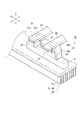
本発明の第1の実施形態に係る電力変換装置は、図1に示すように、直流電源(図示省略)の正極側及び負極側にそれぞれ接続される一対の直流バスバ電極21,22と、一対の直流バスバ電極21,22に電気的に接続された放電抵抗器10及び電子部品(平滑用コンデンサ)1と、放電抵抗器10に熱的に接触した冷却器5とを備える。本明細書において、放電抵抗器10と冷却器5とが「熱的に接触する」とは、放電抵抗器10と冷却器5との間で熱交換可能な状態にあることを意味し、放電抵抗器10と冷却器5とが直接機械的に接している場合に限られず、例えば放熱グリス等の熱伝導性の高い物質が中間に介在している状態を含む。なお、図1において、紙面に向かって左右方向をx軸方向、前後方向をy軸方向、上下方向をz軸方向として説明する。
(First embodiment)
As shown in FIG. 1, the power converter according to the first embodiment of the present invention includes a pair of DC bus bar electrodes 21 and 22 connected to a positive electrode side and a negative electrode side of a DC power source (not shown), and a pair The discharge resistor 10 and the electronic component (smoothing capacitor) 1 electrically connected to the direct current bus bar electrodes 21 and 22 and the cooler 5 that is in thermal contact with the discharge resistor 10 are provided. In the present specification, the term “thermal contact” between the discharge resistor 10 and the cooler 5 means that the heat can be exchanged between the discharge resistor 10 and the cooler 5. It is not limited to the case where the resistor 10 and the cooler 5 are in direct mechanical contact, and includes a state in which a substance having high thermal conductivity such as heat-dissipating grease is interposed in the middle. In FIG. 1, the left and right direction toward the paper surface is described as the x-axis direction, the front-rear direction is the y-axis direction, and the vertical direction is the z-axis direction.

本発明の第1の実施形態に係る電力変換装置は、直流電源を交流電源に変換するインバータであり、例えば図2に示すような電気自動車等の車両のモータ駆動システムに適用可能である。図2に示したモータ駆動システムは、直流電源100と、直流電源100の電流を平滑化する平滑用コンデンサ1と、イグニッションスイッチをオフした時に、平滑用コンデンサ1に蓄積された電荷を放電する放電抵抗102と、複数の半導体モジュール111〜116と、半導体モジュール111〜116を制御する制御回路104と、半導体モジュール111〜116により駆動される三相交流モータ103とを備える。複数の半導体モジュール111〜116のそれぞれは、絶縁ゲート型バイポーラトランジスタ(IGBT)等のスイッチング素子121及び保護ダイオード122を有する。   The power conversion device according to the first embodiment of the present invention is an inverter that converts a DC power source into an AC power source, and can be applied to a motor drive system of a vehicle such as an electric vehicle as shown in FIG. The motor drive system shown in FIG. 2 includes a DC power supply 100, a smoothing capacitor 1 that smoothes the current of the DC power supply 100, and a discharge that discharges charges accumulated in the smoothing capacitor 1 when the ignition switch is turned off. A resistor 102, a plurality of semiconductor modules 111 to 116, a control circuit 104 for controlling the semiconductor modules 111 to 116, and a three-phase AC motor 103 driven by the semiconductor modules 111 to 116 are provided. Each of the plurality of semiconductor modules 111 to 116 includes a switching element 121 such as an insulated gate bipolar transistor (IGBT) and a protection diode 122.

図2に示した平滑用コンデンサ101及び放電抵抗102が、図1に示した平滑用コンデンサ1及び放電抵抗器10にそれぞれ対応する。なお、図2に示した半導体モジュール111〜116等も図1に示した筐体7内に配置されるが、図1では図示を省略する。   The smoothing capacitor 101 and the discharge resistor 102 shown in FIG. 2 correspond to the smoothing capacitor 1 and the discharge resistor 10 shown in FIG. 1, respectively. Note that the semiconductor modules 111 to 116 and the like shown in FIG. 2 are also arranged in the housing 7 shown in FIG. 1, but the illustration is omitted in FIG.

図1に示すように、放電抵抗器10及び平滑用コンデンサ1は、筐体7内に配置されている。筐体7の上部の開口部は蓋6により閉じられ、蓋6はネジ等の固定具71,72で筐体7に固定されている。平滑用コンデンサ1はネジ等の固定具72,75により筐体7に固定されている。一対の直流バスバ電極21,22は、平滑用コンデンサ1にネジ等の固定具74で固定されている。なお、放電抵抗器10及び平滑用コンデンサ1等の筐体7内の位置関係は特に限定されない。   As shown in FIG. 1, the discharge resistor 10 and the smoothing capacitor 1 are disposed in the housing 7. The opening at the top of the housing 7 is closed by a lid 6, and the lid 6 is fixed to the housing 7 by fixing tools 71 and 72 such as screws. The smoothing capacitor 1 is fixed to the housing 7 by fasteners 72 and 75 such as screws. The pair of DC bus bar electrodes 21 and 22 are fixed to the smoothing capacitor 1 by a fixing tool 74 such as a screw. The positional relationship within the housing 7 such as the discharge resistor 10 and the smoothing capacitor 1 is not particularly limited.

冷却器5は、筐体7に一体的に形成されており、冷却フィン53により区切られた冷却水路52と、冷却フィン53上に設けられた冷却プレート51とを有する。なお、冷却器5は、筐体7とは独立した部品であってもよい。冷却器5は、放電抵抗器10が平滑用コンデンサ1に蓄積された電荷を放電する際に発生した熱(図1に矢印で図示)を冷却するとともに、一対の直流バスバ電極21,22から放電抵抗器10を介して伝わる熱(図1に矢印で図示)も冷却する。   The cooler 5 is formed integrally with the housing 7, and includes a cooling water channel 52 partitioned by the cooling fins 53 and a cooling plate 51 provided on the cooling fins 53. The cooler 5 may be a component independent of the housing 7. The cooler 5 cools heat (shown by arrows in FIG. 1) generated when the discharge resistor 10 discharges the electric charge accumulated in the smoothing capacitor 1 and discharges from the pair of DC bus bar electrodes 21 and 22. It also cools the heat transferred through the resistor 10 (shown by arrows in FIG. 1).

一対の直流バスバ電極21,22の一端は、蓋6に設けられた開口部から外部へ延伸し、図示を省略した直流電源に接続される。一対の直流バスバ電極21,22は、図1及び図3に示すように、板状の金属部材であり、直流電源側はz軸方向に互いに平行に延伸し、筐体7内で直角に折れ曲がって平滑用コンデンサ1までx軸方向に互いに平行に延伸する。   One end of the pair of DC bus bar electrodes 21 and 22 extends outward from an opening provided in the lid 6 and is connected to a DC power supply (not shown). The pair of DC bus bar electrodes 21 and 22 are plate-like metal members as shown in FIGS. 1 and 3, and the DC power supply side extends parallel to each other in the z-axis direction and is bent at a right angle in the housing 7. Thus, the smoothing capacitor 1 extends parallel to each other in the x-axis direction.

放電抵抗器10は、図1及び図3に示すように、平滑用コンデンサ1に蓄積された電荷を放電するための絶縁体で覆われた放電抵抗素子4と、一対の直流バスバ電極21,22から放電抵抗素子4までを繋ぐ一対の金属製バスバ電極31,32とを備える。一対の金属製バスバ電極31,32は、銅又はアルミニウム等の板状の金属材料からなる剛体である。なお、本明細書における「剛体」とは、放電抵抗素子4を冷却器5に押しつけることができないハーネス等と区別して、放電抵抗素子4を冷却器5に押しつけることが可能な程度の剛性を有する固体を意味する。例えば、一対の金属製バスバ電極31,32の高さは150mm程度、幅は15mm程度、厚さは1mm程度である。   As shown in FIGS. 1 and 3, the discharge resistor 10 includes a discharge resistor element 4 covered with an insulator for discharging charges accumulated in the smoothing capacitor 1, and a pair of DC bus bar electrodes 21 and 22. And a pair of metal bus bar electrodes 31, 32 connecting the discharge resistance element 4. The pair of metal bus bar electrodes 31 and 32 is a rigid body made of a plate-like metal material such as copper or aluminum. In this specification, the “rigid body” is distinguished from a harness or the like that cannot press the discharge resistance element 4 against the cooler 5 and has a rigidity that can press the discharge resistance element 4 against the cooler 5. Means solid. For example, the height of the pair of metal bus bar electrodes 31 and 32 is about 150 mm, the width is about 15 mm, and the thickness is about 1 mm.

一対の金属製バスバ電極31,32は、放電抵抗素子4に一端が接し、z軸方向に延伸する本体部31a,32aと、本体部31a,32aの他端から折り曲がり、y軸方向に互いの内側に延伸する接続部31b,32bとをそれぞれ備える。例えば、本体部31a,32aは、放電抵抗素子4に圧接により固定されている。一方、接続部31b,32bは、圧接や溶接により一対の直流バスバ電極21,22に固定されていてもよく、ネジ等の固定具により一対の直流バスバ電極21,22に固定されていてもよい。なお、一対の直流バスバ電極21,22との接触面積を大きくするため接続部31b,32bを有することが好ましいが、接続部31b,32bがなく、本体部31a,32aの他端が一対の直流バスバ電極21,22に固定されていてもよい。   The pair of metal bus bar electrodes 31 and 32 are in contact with the discharge resistance element 4 at one end, and are bent from the main body portions 31a and 32a extending in the z-axis direction and the other end of the main body portions 31a and 32a, and are mutually connected in the y-axis direction. And connection portions 31b and 32b extending inward. For example, the main body portions 31 a and 32 a are fixed to the discharge resistance element 4 by pressure contact. On the other hand, the connecting portions 31b and 32b may be fixed to the pair of DC bus bar electrodes 21 and 22 by pressure welding or welding, or may be fixed to the pair of DC bus bar electrodes 21 and 22 by a fixing tool such as a screw. . In order to increase the contact area between the pair of DC bus bar electrodes 21 and 22, the connection portions 31b and 32b are preferably provided. However, the connection portions 31b and 32b are not provided, and the other end of the main body portions 31a and 32a is a pair of direct currents. The bus bar electrodes 21 and 22 may be fixed.

放電抵抗素子4は、冷却器5の冷却プレート51上に配置されている。放電抵抗素子4は、少なくともその一部が冷却器5の冷却プレート51に直接接触(圧接)していることが好ましい。なお、放電抵抗素子4は、冷却プレート51上に放熱グリス等を介して配置されてもよい。ここで、一対の直流バスバ電極21,22と一対の金属製バスバ電極31,32の接続部31b,32bとの接続部分の中心C1と、放電抵抗素子4の重心C2とが、正投影面(z軸方向)からみて略一致することが好ましい。   The discharge resistance element 4 is disposed on the cooling plate 51 of the cooler 5. It is preferable that at least a part of the discharge resistance element 4 is in direct contact (pressure contact) with the cooling plate 51 of the cooler 5. In addition, the discharge resistance element 4 may be arrange | positioned through the thermal radiation grease etc. on the cooling plate 51. FIG. Here, the center C1 of the connection portion between the pair of DC bus bar electrodes 21 and 22 and the connection portions 31b and 32b of the pair of metal bus bar electrodes 31 and 32 and the center of gravity C2 of the discharge resistance element 4 are orthographic projection planes ( It is preferable that they substantially coincide with each other when viewed from the z-axis direction).

本発明の第1の実施形態に係る電力変換装置の組立作業時の一例においては、まず一対の直流バスバ電極21,22と一対の金属製バスバ電極31,32の接続部31b,32bとを互いに固定してから、これの本体部31a,32a側を冷却器5上に配置した放電抵抗素子4に押しつけることにより、放電抵抗素子4を冷却器5上に固定する。この際、一対の金属製バスバ電極31,32と放電抵抗素子4とが剛体同士の接続となるので、放電抵抗素子4を冷却器5に押し付けて固定させることができる。したがって、一対の直流バスバ電極21,22と放電抵抗素子4とを細く柔らかいハーネスで接続する場合と比較して作業が容易となり、放電抵抗素子4を冷却器5に固定するのに要する作業時間を短縮することができる。また、ロボットによる自動組立の場合においては、一対の直流バスバ電極21,22と一対の金属製バスバ電極31,32とのセットを放電抵抗素子4に対して押し当てればよいので、ハンドリングが容易となる。   In an example during assembly of the power conversion device according to the first embodiment of the present invention, first, the pair of DC bus bar electrodes 21, 22 and the connection portions 31b, 32b of the pair of metal bus bar electrodes 31, 32 are mutually connected. After fixing, the discharge resistance element 4 is fixed on the cooler 5 by pressing the main body portions 31 a and 32 a side against the discharge resistance element 4 disposed on the cooler 5. At this time, since the pair of metal bus bar electrodes 31 and 32 and the discharge resistance element 4 are connected to each other by a rigid body, the discharge resistance element 4 can be pressed against the cooler 5 and fixed. Therefore, the work becomes easier compared to the case where the pair of DC bus bar electrodes 21 and 22 and the discharge resistance element 4 are connected by a thin and soft harness, and the work time required to fix the discharge resistance element 4 to the cooler 5 is reduced. It can be shortened. Further, in the case of automatic assembly by a robot, since a set of a pair of DC bus bar electrodes 21 and 22 and a pair of metal bus bar electrodes 31 and 32 may be pressed against the discharge resistance element 4, handling is easy. Become.

また、一対の直流バスバ電極21,22と放電抵抗素子4とを細く柔らかいハーネスで接続する場合と比較して、放電抵抗素子4を冷却器5に押し付けることができるので、冷却効果を向上させることができ、放電抵抗素子4の温度上昇をより低減することができる。   Moreover, since the discharge resistance element 4 can be pressed against the cooler 5 as compared with the case where the pair of DC bus bar electrodes 21 and 22 and the discharge resistance element 4 are connected with a thin and soft harness, the cooling effect is improved. The temperature rise of the discharge resistance element 4 can be further reduced.

これに関して、図4(a)に、本発明の実施形態に係る金属製バスバ電極31を使用した場合の温度分布の測定結果を示し、図4(b)に、比較例として、金属製バスバ電極31の代わりにハーネス31xを使用した場合の温度分布の測定結果を示す。図4(a)において、直流バスバ電極21の温度は66.5℃、冷却器5の温度は48℃であり、直流バスバ電極21の損失は11W、金属製バスバ電極31の損失は0W、放電抵抗素子4の損失は2.7Wである。   In this regard, FIG. 4A shows a measurement result of the temperature distribution when the metal bus bar electrode 31 according to the embodiment of the present invention is used, and FIG. 4B shows a metal bus bar electrode as a comparative example. The measurement result of the temperature distribution at the time of using the harness 31x instead of 31 is shown. 4A, the temperature of the DC bus bar electrode 21 is 66.5 ° C., the temperature of the cooler 5 is 48 ° C., the loss of the DC bus bar electrode 21 is 11 W, the loss of the metal bus bar electrode 31 is 0 W, and the discharge. The loss of the resistance element 4 is 2.7 W.

一方、図4(b)の比較例においては、直流バスバ電極21の温度は80.5℃、冷却器5の温度は48℃であり、直流バスバ電極21の損失は11W、ハーネス31xの損失は0W、放電抵抗素子4の損失は2.7Wである。図4(a)及び図4(b)から、本発明の実施形態に係る金属製バスバ電極31を使用した場合の方が、図4(b)に示した比較例よりも、直流バスバ電極21の温度が14℃低減していることが分かる。   On the other hand, in the comparative example of FIG. 4B, the temperature of the DC bus bar electrode 21 is 80.5 ° C., the temperature of the cooler 5 is 48 ° C., the loss of the DC bus bar electrode 21 is 11 W, and the loss of the harness 31x is The loss of 0 W and the discharge resistance element 4 is 2.7 W. From FIG. 4A and FIG. 4B, the direct current bus bar electrode 21 is better when the metal bus bar electrode 31 according to the embodiment of the present invention is used than when the comparative example shown in FIG. It can be seen that the temperature is reduced by 14 ° C.

本発明の第1の実施形態によれば、一対の直流バスバ電極21,22と放電抵抗素子4との間に一対の金属製バスバ電極31,32を配置し、一対の金属製バスバ電極31,32により放電抵抗素子4を冷却器5に押しつけて固定することにより、ハーネスのような柔らかい部品を組み付ける場合と比較して、作業時間の短縮を図ることができるとともに、ロボットを使用した自動化組立も容易となり、生産コストを低減することができる。   According to the first embodiment of the present invention, a pair of metal bus bar electrodes 31, 32 are arranged between the pair of DC bus bar electrodes 21, 22 and the discharge resistance element 4, and the pair of metal bus bar electrodes 31, By pressing and fixing the discharge resistance element 4 to the cooler 5 by 32, the working time can be shortened as compared with the case where a soft part such as a harness is assembled, and automatic assembly using a robot is also possible. It becomes easy and the production cost can be reduced.

また、一対の直流バスバ電極21,22に電子部品として平滑用コンデンサ1を接続することにより、平滑用コンデンサ1に蓄積された電荷を放電抵抗器10により放電するとともに、平滑用コンデンサ1で発生した熱を放電抵抗器10を介して放熱させることができる。   Further, by connecting the smoothing capacitor 1 as an electronic component to the pair of DC bus bar electrodes 21 and 22, the electric charge accumulated in the smoothing capacitor 1 is discharged by the discharge resistor 10 and is generated in the smoothing capacitor 1. Heat can be dissipated through the discharge resistor 10.

また、放電抵抗素子4の少なくとも一部が冷却器5に直接接触することにより、冷却効果が向上し、高温となる一対の直流バスバ電極21,22、一対の金属製バスバ電極31,32及び放電抵抗素子4の温度上昇を低減することができる。したがって、筐体7の内部雰囲気温度を低減可能となるとともに、一対の直流バスバ電極21,22及び一対の金属製バスバ電極31,32の板厚を薄くでき、部品費の低減及び軽量化を図ることができる。   Further, when at least a part of the discharge resistance element 4 is in direct contact with the cooler 5, the cooling effect is improved, and the pair of DC bus bar electrodes 21 and 22, the pair of metal bus bar electrodes 31 and 32, and the discharge, The temperature rise of the resistance element 4 can be reduced. Therefore, the internal atmospheric temperature of the housing 7 can be reduced, and the plate thickness of the pair of DC bus bar electrodes 21 and 22 and the pair of metal bus bar electrodes 31 and 32 can be reduced, thereby reducing the component cost and weight. be able to.

また、一対の直流バスバ電極21,22と一対の金属製バスバ電極31,32の接続部31b,32bとの接続部分の中心C1と、放電抵抗素子4の重心C2とが、正投影面からみて略一致することにより、組立時に一対の金属製バスバ電極31,32を放電抵抗素子4に押しつけたときに放電抵抗素子4が固定しやすく、組み付け作業がより容易となる。   Further, the center C1 of the connection portion between the pair of DC bus bar electrodes 21 and 22 and the connection portions 31b and 32b of the pair of metal bus bar electrodes 31 and 32 and the center of gravity C2 of the discharge resistance element 4 are seen from the orthographic projection plane. By substantially matching, when the pair of metal bus bar electrodes 31 and 32 are pressed against the discharge resistance element 4 at the time of assembly, the discharge resistance element 4 is easily fixed, and the assembling work becomes easier.

(第2の実施形態)
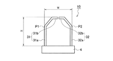
本発明の第2の実施形態に係る電力変換装置は、図5に示すように、放電抵抗器10の一対の金属製バスバ電極31,32のそれぞれに、1点の屈曲点P1,P2を設けている点が、本発明の第1の実施形態に係る電力変換装置と異なる。本発明の第2の実施形態に係る電力変換装置の他の構成は、本発明の第1の実施形態に係る電力変換装置と同様であるので、重複した説明を省略する。
(Second Embodiment)
As shown in FIG. 5, the power converter according to the second embodiment of the present invention is provided with one bending point P <b> 1, P <b> 2 on each of the pair of metal bus bar electrodes 31, 32 of the discharge resistor 10. This is different from the power converter according to the first embodiment of the present invention. Since the other structure of the power converter device which concerns on the 2nd Embodiment of this invention is the same as that of the power converter device which concerns on the 1st Embodiment of this invention, the overlapping description is abbreviate | omitted.

図5では、一対の金属製バスバ電極31,32の本体部31a,32aのそれぞれに1点の屈曲点P1,P2を設けた場合を示すが、本体部31a,32aに設けられる屈曲点P1,P2の数は限定されない。例えば、一対の金属製バスバ電極31,32の本体部31a,32aのそれぞれに2点以上の屈曲点を設けていてもよい。また、一対の金属製バスバ電極31,32の本体部31a,32aが屈曲点P1,P2によりy軸方向に対して屈曲する角度は適宜設定可能である。なお、図5では本体部31a,32aが内側に屈曲しているが、外側に屈曲していてもよい。   FIG. 5 shows a case where one bending point P1, P2 is provided in each of the main body portions 31a, 32a of the pair of metal bus bar electrodes 31, 32, but the bending points P1, 1 provided in the main body portions 31a, 32a are shown. The number of P2 is not limited. For example, two or more bending points may be provided in each of the main body portions 31a and 32a of the pair of metal bus bar electrodes 31 and 32. The angle at which the body portions 31a, 32a of the pair of metal bus bar electrodes 31, 32 are bent with respect to the y-axis direction by the bending points P1, P2 can be set as appropriate. In FIG. 5, the main body portions 31a and 32a are bent inward, but may be bent outward.

図6に示すように、放電抵抗素子4又は一対の直流バスバ電極21,22を経由した平滑用コンデンサ1からの熱により、一対の金属製バスバ電極31,32が熱膨張してバネ構造となる。このため、冷却器5へ放電抵抗素子4を強く押付けることができる。なお、図6では、熱膨張による押付け反力を矢印で模式的に示す。更には、一対の金属製バスバ電極31,32の一部に屈曲点P1,P2を設けることにより、屈曲点P1,P2が熱応力を吸収して応力緩和することができる。   As shown in FIG. 6, the heat from the smoothing capacitor 1 via the discharge resistor element 4 or the pair of DC bus bar electrodes 21 and 22 causes the pair of metal bus bar electrodes 31 and 32 to thermally expand to form a spring structure. . For this reason, the discharge resistance element 4 can be strongly pressed against the cooler 5. In addition, in FIG. 6, the pressing reaction force by thermal expansion is typically shown with an arrow. Furthermore, by providing the bending points P1 and P2 on a part of the pair of metal bus bar electrodes 31 and 32, the bending points P1 and P2 can absorb the thermal stress and relieve the stress.

本発明の第2の実施形態によれば、本発明の第1の実施形態と同様に、一対の直流バスバ電極21,22と放電抵抗素子4との間に一対の金属製バスバ電極31,32を配置し、一対の金属製バスバ電極31,32により放電抵抗素子4を冷却器5に押しつけて固定することにより、ハーネスのような柔らかい部品を組み付ける場合と比較して、作業時間の短縮を図ることができるとともに、ロボットを使用した自動化組立も容易となり、生産コストを低減することができる。   According to the second embodiment of the present invention, a pair of metal bus bar electrodes 31, 32 between the pair of DC bus bar electrodes 21, 22 and the discharge resistance element 4, as in the first embodiment of the present invention. And the discharge resistance element 4 is pressed against and fixed to the cooler 5 by the pair of metal bus bar electrodes 31 and 32, so that the working time is shortened as compared with the case where a soft part such as a harness is assembled. In addition, automated assembly using a robot is facilitated, and production costs can be reduced.

また、本発明の第2の実施形態によれば、一対の金属製バスバ電極31,32の一部に1点以上の屈曲点P1,P2を設けることにより、冷却器5へ放電抵抗素子4を強く押付けることができるとともに、屈曲点P1,P2が熱応力を吸収して応力緩和することができる。更には、振動応力を緩和することができ、車体マウント、駆動用モータに固定されるインバータにおける耐車載振動性を向上させることができる。   Further, according to the second embodiment of the present invention, the discharge resistance element 4 is connected to the cooler 5 by providing one or more bending points P1 and P2 on a part of the pair of metal bus bar electrodes 31 and 32. While being able to press strongly, the bending points P1 and P2 can absorb thermal stress and relieve stress. Furthermore, vibration stress can be relieved, and the in-vehicle vibration resistance of the inverter fixed to the vehicle body mount and the drive motor can be improved.

(第3の実施形態)
本発明の第3の実施形態に係る電力変換装置は、図7に示すように、一対の金属製バスバ電極31,32の高さHと、一対の金属製バスバ電極31,32と放電抵抗素子4との固定点間の距離(換言すれば、一対の金属製バスバ電極31,32が並ぶ方向(y軸方向)の幅)Wとが、下記式(1)を満たす関係となるように規定される点が、本発明の第2の実施形態と異なる。

H<W×3.5 …(1)
(Third embodiment)
As shown in FIG. 7, the power converter according to the third embodiment of the present invention includes a height H of a pair of metal bus bar electrodes 31, 32, a pair of metal bus bar electrodes 31, 32, and a discharge resistance element. And the distance between the fixed points of 4 (in other words, the width in the direction in which the pair of metal bus bar electrodes 31 and 32 are arranged (y-axis direction)) W satisfies the following expression (1). This is different from the second embodiment of the present invention.

H <W × 3.5 (1)

即ち、一対の金属製バスバ電極31,32と放電抵抗素子4との固定点間の距離Wに対する一対の金属製バスバ電極31,32の高さHの比率を350%未満とする。例えば、一対の金属製バスバ電極31,32の高さHを148mm、一対の金属製バスバ電極31,32と放電抵抗素子4との固定点間の距離Wを42mmに規定することにより、比率W/Hは236%となる。本発明の第3の実施形態に係る電力変換装置の他の構成は、本発明の第2の実施形態に係る電力変換装置と同様であるので、重複した説明を省略する。   That is, the ratio of the height H of the pair of metal bus bar electrodes 31, 32 to the distance W between the fixed points of the pair of metal bus bar electrodes 31, 32 and the discharge resistance element 4 is set to less than 350%. For example, by defining the height H of the pair of metal bus bar electrodes 31 and 32 as 148 mm and the distance W between the fixed points of the pair of metal bus bar electrodes 31 and 32 and the discharge resistance element 4 as 42 mm, the ratio W / H is 236%. Since the other structure of the power converter device which concerns on the 3rd Embodiment of this invention is the same as that of the power converter device which concerns on the 2nd Embodiment of this invention, the overlapping description is abbreviate | omitted.

図8は、インバータが搭載されるエンジンルーム内における車両からの入力振動を表すパワースペクトル密度(PSD)波形を示す。図8の横軸はインバータの振動周波数を示し、縦軸は車両から受ける振幅を示す。図8に示すPSD波形において、エンジンルーム内に搭載される部品は、振動周波数が100Hz以上であれば、振幅が極めて小さい値となる。このため、インバータ内の構成部品は、固有値を100Hz以上とすることが望ましい。   FIG. 8 shows a power spectral density (PSD) waveform representing the input vibration from the vehicle in the engine room where the inverter is mounted. The horizontal axis of FIG. 8 shows the vibration frequency of the inverter, and the vertical axis shows the amplitude received from the vehicle. In the PSD waveform shown in FIG. 8, the component mounted in the engine room has a very small amplitude if the vibration frequency is 100 Hz or more. For this reason, as for the component in an inverter, it is desirable for an eigenvalue to be 100 Hz or more.

ここで、図9(a)〜図9(c)に、一対の金属製バスバ電極31,32と放電抵抗素子4との固定点間の距離Wを42mmで固定し、一対の金属製バスバ電極31,32の高さHを15mm、40mm、148mmと変化させた放電抵抗器10のモデルA、B、Cを示す。図9(a)〜図9(c)のモデルA、B、Cにおいて、一対の金属製バスバ電極31,32と放電抵抗素子4との固定点間の距離Wに対する一対の金属製バスバ電極31,32の高さHの比率H/Wはそれぞれ、35%、94%、236%である。   Here, in FIG. 9A to FIG. 9C, the distance W between the fixed points of the pair of metal bus bar electrodes 31 and 32 and the discharge resistance element 4 is fixed at 42 mm, and the pair of metal bus bar electrodes. Models A, B, and C of the discharge resistor 10 in which the heights H of 31 and 32 are changed to 15 mm, 40 mm, and 148 mm are shown. In models A, B, and C of FIGS. 9A to 9C, the pair of metal bus bar electrodes 31 with respect to the distance W between the fixed points of the pair of metal bus bar electrodes 31 and 32 and the discharge resistance element 4. 32, the ratio H / W of the height H is 35%, 94% and 236%, respectively.

図10は、一対の金属製バスバ電極31,32と放電抵抗素子4との固定点間の距離Wに対する一対の金属製バスバ電極31,32の高さHの比率H/Wと固有振動数の相関を示す。図10に示すように、一対の金属製バスバ電極31,32と放電抵抗素子4との固定点間の距離Wに対する一対の金属製バスバ電極31,32の高さHの比率を、350%未満とすることで、車両からの振動入力に対し、共振を避けられる固有振動数100Hz以上とすることができる。   FIG. 10 shows the ratio H / W of the height H of the pair of metal bus bar electrodes 31, 32 to the distance W between the fixed points of the pair of metal bus bar electrodes 31, 32 and the discharge resistance element 4, and the natural frequency. Show correlation. As shown in FIG. 10, the ratio of the height H of the pair of metal bus bar electrodes 31, 32 to the distance W between the fixed points of the pair of metal bus bar electrodes 31, 32 and the discharge resistance element 4 is less than 350%. By doing so, it is possible to achieve a natural frequency of 100 Hz or more that can avoid resonance with respect to vibration input from the vehicle.

本発明の第3の実施形態によれば、本発明の第1及び2の実施形態と同様に、一対の直流バスバ電極21,22と放電抵抗素子4との間に一対の金属製バスバ電極31,32を配置し、一対の金属製バスバ電極31,32により放電抵抗素子4を冷却器5に押しつけて固定することにより、ハーネスのような柔らかい部品を組み付ける場合と比較して、作業時間の短縮を図ることができるとともに、ロボットを使用した自動化組立も容易となり、生産コストを低減することができる。   According to the third embodiment of the present invention, as in the first and second embodiments of the present invention, a pair of metal bus bar electrodes 31 between the pair of DC bus bar electrodes 21, 22 and the discharge resistance element 4. 32, and the discharge resistance element 4 is pressed against the cooler 5 by the pair of metal bus bar electrodes 31 and 32 and fixed to the cooler 5, thereby shortening the working time as compared with the case where a soft part such as a harness is assembled. In addition, automatic assembly using a robot is facilitated, and production costs can be reduced.

また、本発明の第2の実施形態と同様に、一対の金属製バスバ電極31,32の一部に1点以上の屈曲点P1,P2を設けることにより、冷却器5へ放電抵抗素子4を強く押付けることができるとともに、屈曲点P1,P2が熱応力を吸収して応力緩和することができる。更には、振動応力を緩和することができ、車体マウント、駆動用モータに固定されるインバータにおける耐車載振動性を向上させることができる。   Similarly to the second embodiment of the present invention, one or more bending points P1 and P2 are provided on a part of the pair of metal bus bar electrodes 31 and 32, whereby the discharge resistance element 4 is connected to the cooler 5. While being able to press strongly, the bending points P1 and P2 can absorb thermal stress and relieve stress. Furthermore, vibration stress can be relieved, and the in-vehicle vibration resistance of the inverter fixed to the vehicle body mount and the drive motor can be improved.

また、本発明の第3の実施形態によれば、一対の金属製バスバ電極31,32と放電抵抗素子4との固定点間の距離Wに対する一対の金属製バスバ電極31,32の高さHの比率を350%未満とすることで、車両振動入力に対し共振しないよう最適化することができ、所望の耐車載性を得ることができる。   Further, according to the third embodiment of the present invention, the height H of the pair of metal bus bar electrodes 31, 32 with respect to the distance W between the fixed points of the pair of metal bus bar electrodes 31, 32 and the discharge resistance element 4. By making the ratio of less than 350%, it can be optimized so as not to resonate with respect to vehicle vibration input, and a desired in-vehicle resistance can be obtained.

(その他の実施形態)
上記のように、本発明の第1〜第3の実施形態を記載したが、この開示の一部をなす論述及び図面はこの発明を限定するものであると理解すべきではない。この開示から当業者には様々な代替実施の形態、実施例及び運用技術が明らかとなろう。
(Other embodiments)
As described above, the first to third embodiments of the present invention have been described. However, it should not be understood that the descriptions and drawings constituting a part of this disclosure limit the present invention. From this disclosure, various alternative embodiments, examples and operational techniques will be apparent to those skilled in the art.

例えば、一対の金属製バスバ電極31,32の形状は、放電抵抗素子4を冷却器5に押しつけることが可能であれば特に限定されない。例えば、図3では一対の金属製バスバ電極31,32の接続部31b,32bが内側に向かって延伸する場合を示したが、外側に向かって延伸していてもよい。   For example, the shape of the pair of metal bus bar electrodes 31 and 32 is not particularly limited as long as the discharge resistance element 4 can be pressed against the cooler 5. For example, FIG. 3 shows the case where the connection portions 31b and 32b of the pair of metal bus bar electrodes 31 and 32 extend inward, but they may extend outward.

また、本発明の第1〜第3の実施形態においては、電子部品1が平滑用コンデンサである場合を説明したが、電子部品1が他の部品であってもよい。   In the first to third embodiments of the present invention, the case where the electronic component 1 is a smoothing capacitor has been described, but the electronic component 1 may be another component.

1,101…電子部品(平滑用コンデンサ)
4…放電抵抗素子
5…冷却器
6…蓋
10…放電抵抗器
21,22…直流バスバ電極
31,32…金属製バスバ電極
51…冷却プレート
52…冷却水路
53…冷却フィン
71〜75…固定具
100…直流電源
102…放電抵抗
103…三相交流モータ
104…制御回路
111〜116…半導体モジュール
121…スイッチング素子
122…保護ダイオード
1,101 ... Electronic component (smoothing capacitor)
DESCRIPTION OF SYMBOLS 4 ... Discharge resistance element 5 ... Cooler 6 ... Cover 10 ... Discharge resistor 21, 22 ... DC bus bar electrode 31, 32 ... Metal bus bar electrode 51 ... Cooling plate 52 ... Cooling water channel 53 ... Cooling fins 71-75 ... Fixing tool DESCRIPTION OF SYMBOLS 100 ... DC power supply 102 ... Discharge resistor 103 ... Three-phase AC motor 104 ... Control circuit 111-116 ... Semiconductor module 121 ... Switching element 122 ... Protection diode

Claims (6)

直流電源の正極側及び負極側にそれぞれ接続される一対の直流バスバ電極と、
前記一対の直流バスバ電極に電気的に接続した電子部品と、
前記電子部品に蓄積された電荷を放電する放電抵抗素子と、
前記放電抵抗素子に熱的に接触した冷却器と、
前記一対の直流バスバ電極と前記放電抵抗素子との間に配置され、前記放電抵抗素子を前記冷却器に押しつけて固定する一対の金属製バスバ電極
とを備えることを特徴とする電力変換装置。
A pair of DC bus bar electrodes respectively connected to the positive electrode side and the negative electrode side of the DC power source;
Electronic components electrically connected to the pair of DC bus bar electrodes;
A discharge resistance element for discharging the electric charge accumulated in the electronic component;
A cooler in thermal contact with the discharge resistance element;
A power conversion device comprising: a pair of metal bus bar electrodes arranged between the pair of DC bus bar electrodes and the discharge resistance element and pressing the discharge resistance element against the cooler to fix the same.
前記一対の金属製バスバ電極のそれぞれが屈曲点を有することを特徴とする請求項1に記載の電力変換装置。   The power converter according to claim 1, wherein each of the pair of metal bus bar electrodes has a bending point. 前記一対の金属製バスバ電極と前記放電抵抗素子との固定点間の距離に対する前記一対の金属製バスバ電極の高さの比率を350%未満とすることを特徴とする請求項1又は2に記載の電力変換装置。   3. The ratio of the height of the pair of metal bus bar electrodes to the distance between the fixed points of the pair of metal bus bar electrodes and the discharge resistance element is less than 350%. Power converter. 前記一対の直流バスバ電極に電気的に接続された平滑用コンデンサを更に備えることを特徴とする請求項1〜3のいずれか1項に記載の電力変換装置。   The power converter according to claim 1, further comprising a smoothing capacitor electrically connected to the pair of DC bus bar electrodes. 前記放電抵抗素子と前記冷却器とが直接接触することを特徴とする請求項1〜4のいずれか1項に記載の電力変換装置。   The power converter according to any one of claims 1 to 4, wherein the discharge resistance element and the cooler are in direct contact. 前記一対の金属製バスバ電極と前記一対の直流バスバ電極との接続部の中心と、前記放電抵抗素子の重心とが、正投影面からみたときに略一致することを特徴とする請求項1〜5のいずれか1項に記載の電力変換装置。   The center of the connection portion between the pair of metal bus bar electrodes and the pair of DC bus bar electrodes and the center of gravity of the discharge resistance element substantially coincide when viewed from the orthographic projection plane. The power converter according to any one of 5.
JP2015101535A 2015-05-19 2015-05-19 Electric power conversion system Pending JP2016220360A (en)

Priority Applications (1)

Application Number Priority Date Filing Date Title
JP2015101535A JP2016220360A (en) 2015-05-19 2015-05-19 Electric power conversion system

Applications Claiming Priority (1)

Application Number Priority Date Filing Date Title
JP2015101535A JP2016220360A (en) 2015-05-19 2015-05-19 Electric power conversion system

Publications (1)

Publication Number Publication Date
JP2016220360A true JP2016220360A (en) 2016-12-22

Family

ID=57578733

Family Applications (1)

Application Number Title Priority Date Filing Date
JP2015101535A Pending JP2016220360A (en) 2015-05-19 2015-05-19 Electric power conversion system

Country Status (1)

Country Link
JP (1) JP2016220360A (en)

Cited By (3)

* Cited by examiner, † Cited by third party
Publication number Priority date Publication date Assignee Title
JP2018196272A (en) * 2017-05-19 2018-12-06 三菱電機株式会社 Inverter device
JPWO2018211580A1 (en) * 2017-05-16 2020-03-12 日産自動車株式会社 Power converter
JP2020145791A (en) * 2019-03-04 2020-09-10 トヨタ自動車株式会社 Power conversion device

Cited By (4)

* Cited by examiner, † Cited by third party
Publication number Priority date Publication date Assignee Title
JPWO2018211580A1 (en) * 2017-05-16 2020-03-12 日産自動車株式会社 Power converter
JP2018196272A (en) * 2017-05-19 2018-12-06 三菱電機株式会社 Inverter device
JP2020145791A (en) * 2019-03-04 2020-09-10 トヨタ自動車株式会社 Power conversion device
JP7172743B2 (en) 2019-03-04 2022-11-16 株式会社デンソー power converter

Similar Documents

Publication Publication Date Title
JP6919348B2 (en) Power converter
JP4452952B2 (en) Power converter
JP5823020B2 (en) Power converter
US11158563B2 (en) Power semiconductor module and vehicle
JP5760985B2 (en) Power converter
US9992915B2 (en) Power conversion device
JP6180857B2 (en) Power converter
JP6283379B2 (en) Capacitor layout
WO2019208406A1 (en) Power conversion device
JP2016220360A (en) Electric power conversion system
JP6576360B2 (en) Power converter
JP6457895B2 (en) Capacitor module
JP5900260B2 (en) Power converter
WO2013061786A1 (en) Power conversion device
JP2019022293A (en) Power supply device
JP7074486B2 (en) Secondary battery module
JP6115430B2 (en) Power converter
WO2021053975A1 (en) Power converter and motor-integrated power converter
JP6648859B2 (en) Power converter
JP6451571B2 (en) Power converter
JP5459055B2 (en) Power converter and circuit board vibration suppression structure
JP7319945B2 (en) power converter
US20220061185A1 (en) Power conversion device
JP7288363B2 (en) Electronics and electronic controllers
JP7007131B2 (en) Heat dissipation structure in circuit board equipment