JP2016217152A - Muffler structure - Google Patents
Muffler structure Download PDFInfo
- Publication number
- JP2016217152A JP2016217152A JP2015099044A JP2015099044A JP2016217152A JP 2016217152 A JP2016217152 A JP 2016217152A JP 2015099044 A JP2015099044 A JP 2015099044A JP 2015099044 A JP2015099044 A JP 2015099044A JP 2016217152 A JP2016217152 A JP 2016217152A
- Authority
- JP
- Japan
- Prior art keywords
- muffler
- outer cylinder
- exhaust pipe
- exhaust gas
- inner cylinder
- Prior art date
- Legal status (The legal status is an assumption and is not a legal conclusion. Google has not performed a legal analysis and makes no representation as to the accuracy of the status listed.)
- Granted
Links
Images


Abstract
Description
本発明は、マフラ構造に関する。 The present invention relates to a muffler structure.
特許文献1には、外筒及び内筒によってマフラ本体が構成された排気マフラが開示されている。また、外筒と内筒との間の空間に断熱・消音材が充填された構成が開示されている。
ところで、排気管とマフラ本体との接続部分に応力が集中するのを回避するため、排気管をマフラ本体の内部まで挿入して複数の箇所で排気管とマフラ本体とを接続することがある。しかしながら、上記の構成では、マフラ本体の内部に導入された排ガスがマフラ本体の内面に局所的に吹き付けられてマフラ放射音が発生することがある。このため、マフラ放射音を効果的に低減する観点から改善の余地がある。 By the way, in order to avoid stress concentration on the connection portion between the exhaust pipe and the muffler main body, the exhaust pipe may be inserted into the muffler main body to connect the exhaust pipe and the muffler main body at a plurality of locations. However, in the above configuration, exhaust gas introduced into the muffler body may be blown locally on the inner surface of the muffler body to generate muffler sound. For this reason, there is room for improvement from the viewpoint of effectively reducing muffler radiation.
本発明は上記事実を考慮し、排気管がマフラ本体の内部まで挿入された構成において、断熱効果を備えつつ、マフラ放射音を低減することができるマフラ構造を得ることを目的とする。 In view of the above facts, an object of the present invention is to obtain a muffler structure capable of reducing muffler radiation sound while providing a heat insulating effect in a configuration in which an exhaust pipe is inserted into the muffler body.
請求項1に記載の本発明に係るマフラ構造は、外筒と該外筒の内側に配置された内筒とを含んで構成され、内部まで挿入された排気管から排ガスが導入されるマフラ本体と、前記内筒において、前記排気管から導入された排ガスが吹き付けられる部位に形成されると共に、前記外筒から離間する方向に凹んで前記外筒との間に空気層を形成する凹部と前記外筒に当接する凸部とが交互に形成された凹凸部と、を有する。 The muffler structure according to the first aspect of the present invention includes an outer cylinder and an inner cylinder disposed inside the outer cylinder, and a muffler body into which exhaust gas is introduced from an exhaust pipe inserted to the inside. And in the inner cylinder, a recess that is formed in a portion to which the exhaust gas introduced from the exhaust pipe is sprayed, is recessed in a direction away from the outer cylinder, and forms an air layer between the outer cylinder and the inner cylinder And a concavo-convex portion in which convex portions abutting on the outer cylinder are alternately formed.
請求項1に記載の本発明に係るマフラ構造では、外筒と内筒とを含んでマフラ本体が構成されており、このマフラ本体には、排気管が挿入されている。そして、この排気管からマフラ本体へ排ガスが導入される。また、内筒には、凹部と凸部とが交互に形成された凹凸部が設けられている。ここで、凹凸部は、マフラ本体に導入された排ガスが吹き付けられる部位に形成されている。また、凹凸部を構成する凹部は、外筒から離間する方向に凹んでおり、この凹部によって内筒と外筒との間に空気層が形成されている。これにより、凹凸部に排ガスが吹き付けられて凹凸部が高温になった場合でも、空気層によって内筒から外筒への熱伝導を抑制することができる。すなわち、排ガスが吹き付けられる部位に空気層が形成されていない構成と比較して、断熱効果を得ることができる。 In the muffler structure according to the first aspect of the present invention, a muffler main body is configured including an outer cylinder and an inner cylinder, and an exhaust pipe is inserted into the muffler main body. And exhaust gas is introduce | transduced into a muffler main body from this exhaust pipe. Further, the inner cylinder is provided with uneven portions in which concave portions and convex portions are alternately formed. Here, the concavo-convex portion is formed at a site where the exhaust gas introduced into the muffler body is sprayed. Moreover, the recessed part which comprises an uneven | corrugated | grooved part is dented in the direction spaced apart from an outer cylinder, and the air layer is formed between the inner cylinder and the outer cylinder by this recessed part. Thereby, even when exhaust gas is sprayed on the concavo-convex portion and the concavo-convex portion becomes high temperature, heat conduction from the inner cylinder to the outer cylinder can be suppressed by the air layer. That is, a heat insulation effect can be obtained as compared with a configuration in which an air layer is not formed at a site where exhaust gas is sprayed.
また、凹凸部を構成する凸部は、外筒に当接している。これにより、マフラ本体における排ガスが吹き付けられる部位の曲げ剛性を高めることができ、この部位の振動を抑制することができる。この結果、マフラ放射音を効果的に低減することができる。 Moreover, the convex part which comprises an uneven | corrugated | grooved part is contact | abutting to the outer cylinder. Thereby, the bending rigidity of the site | part to which the exhaust gas in a muffler main body is sprayed can be improved, and the vibration of this site | part can be suppressed. As a result, muffler radiation sound can be effectively reduced.
以上説明したように、本発明に係るマフラ構造によれば、排気管がマフラ本体の内部まで挿入された構成において、断熱効果を備えつつ、マフラ放射音を低減することができる。 As described above, according to the muffler structure according to the present invention, muffler radiation sound can be reduced while providing a heat insulating effect in the configuration in which the exhaust pipe is inserted into the muffler main body.
(排気系の全体構成)
本発明の実施形態に係るマフラ構造について、図1〜図3に基づいて説明する。なお、各図に適宜示される矢印FRは、マフラ構造が適用された車両の車両前方側を示しており、矢印UPは車両上方側を示しており、矢印OUTは車両幅方向外側を示している。また、以下の説明で特記なく前後、上下、左右の方向を用いる場合は、車両前後方向の前後、車両上下方向の上下、進行方向を向いた場合の左右を示すものとする。
(Overall configuration of exhaust system)
A muffler structure according to an embodiment of the present invention will be described with reference to FIGS. Note that an arrow FR appropriately shown in each drawing indicates a vehicle front side of a vehicle to which a muffler structure is applied, an arrow UP indicates a vehicle upper side, and an arrow OUT indicates an outer side in the vehicle width direction. . Further, in the following description, when using the front / rear, up / down, and left / right directions, the front / rear direction of the vehicle, the up / down direction of the vehicle up / down direction, and the left / right direction in the traveling direction are indicated.
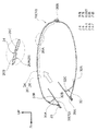
図1に示されるように、マフラ構造は、排気音を低減するためのメインマフラ10を備えている。メインマフラ10は、平面視で車両幅方向を長手方向とする略矩形状に形成されており、このメインマフラ10の車両幅方向中央部には、排気管12が接続されている。
As shown in FIG. 1, the muffler structure includes a
排気管12は、メインマフラ10の前端部に接続されており、メインマフラ10の内部まで挿入されている(図2参照)。また、排気管12は、メインマフラ10から車両前方側へ延在されている。そして、排気管12の前端部は、内燃機関である図示しないエンジンに接続されている。
The
また、エンジンとメインマフラ10との間には、図示しない触媒コンバータ及びサブマフラが配置されている。触媒コンバータは、エンジンから排出された排ガス中の有害成分を還元・酸化によって浄化する構造とされている。サブマフラは、メインマフラ10で吸収しきれない排気音(高周波成分)を吸収する構造とされている。本実施形態の排気系は、以上のように構成されており、エンジンの燃焼などで発生した排ガスが排気管12を介して図示しない触媒コンバータ及びサブマフラを通過して、メインマフラ10へ導入される。
In addition, a catalytic converter and a sub-muffler (not shown) are arranged between the engine and the
メインマフラ10の車両右側には、排気パイプ14が接続されている。排気パイプ14は、メインマフラ10の内部空間と連通されており、メインマフラ10から車両右側へ延出され、さらに車両後方側へ湾曲されている。そして、メインマフラ10へ導入された排ガスは、排気パイプ14を通って大気中へ排出されるように構成されている。
An
メインマフラ10の内部空間は、複数のセパレータ16によって仕切られており、本実施形態では一例として、2枚のセパレータ16によって仕切られている。2枚のセパレータ16は、略平行に配置されてメインマフラ10の内部に架設されており、これらのセパレータ16によってメインマフラ10の内部空間が車両幅方向に3つの空間に仕切られている。ここで、それぞれのセパレータ16には、隣り合う空間と連通する図示しない連通孔が形成されている。このため、メインマフラ10の内部に導入された排ガスは、図示しない連通孔を通ってセパレータ16で仕切られた空間を行き来し、その過程で排気音が低減される構造となっている。なお、上記の構造は、周知であるため、詳細な構造の図示及び説明を省略する。
The internal space of the
(メインマフラの構成)
図3に示されるように、メインマフラ10は、マフラ本体18を備えている。マフラ本体18は、車両幅方向両端部が開口された略筒状の周壁部20と、周壁部20の車両幅方向両端部の開口を閉塞する略平板状の側壁部22とを含んで中空構造とされている。
(Configuration of main muffler)
As shown in FIG. 3, the
側壁部22は、周壁部20を車両幅方向から見た断面形状よりも大径に形成されており、この側壁部22の外周端部は、周壁部20よりも外周側へ突出されている。また、側壁部22には、メインマフラ10を車体に組み付けるための支持部材などが取り付けられる。
The
一方、周壁部20は、図2に示されるように、外板となる外筒24と、内板となる内筒26とを含んで構成されており、車両幅方向から見た断面形状が、車両上下方向が短径方向となる略楕円状に形成されている。また、周壁部20の後端部には、ヘミング加工部20Bが設けられている。このヘミング加工部20Bでは、周壁部20を構成する外筒24及び内筒26の一端側と、外筒24及び内筒26の他端側とがヘミング加工によって結合されており、閉断面を構成している。さらに、後述する凹凸部26Aを除いて外筒24と内筒26とが密着している。
On the other hand, as shown in FIG. 2, the
また、マフラ本体18の前端部には、パイプ挿入孔20Aが形成されている。パイプ挿入孔20Aは、周壁部20の車両幅方向中央部に形成されており、このパイプ挿入孔20Aに排気管12の先端部30が挿入されている。
A
さらに、パイプ挿入孔20Aの孔縁からマフラ本体18の外側へ向かって外筒24及び内筒26が延出されており、排気管12の先端部30の外周面と接合されている。また、マフラ本体18の外面に略円筒状の補強板28が接合されており、マフラ本体18と排気管12との接合部分を補強している。
Further, an
ここで、排気管12の先端部30は、マフラ本体18の内部まで挿入されている。また、先端部30は、マフラ本体18の内部に架設された支持板32に支持されている。
Here, the
支持板32は、マフラ本体18におけるパイプ挿入孔20Aの近傍に配置された略平板状の部材であり、車両前後方向を板厚方向として、車両上方側よりも車両下方側が車両後方側に位置するように傾斜して配置されている。また、支持板32の外周端部には、内筒26の内面に沿って車両後方側へ屈曲された外フランジ部32Aが形成されており、この外フランジ部32Aと内筒26とが接合されている。
The
また、支持板32には、パイプ挿入孔20Aと対向する位置に貫通孔32Bが形成されている。貫通孔32Bは、パイプ挿入孔20Aと略同一の大きさに形成されており、この貫通孔32Bに先端部30が挿入されている。さらに、貫通孔32Bの孔縁から車両後方側へ内フランジ部32Cが延出されており、この内フランジ部32Cが先端部30の外周面と接合されている。一方、先端部30の外周面には、軸方向に間隔をあけて2つの環状突起部30A、30Bが形成されている。そして、この環状突起部30A、30Bの間に支持板32の内フランジ部32Cが挟み込まれており、環状突起部30A、30Bによって先端部30の抜出が防止されている。このようにして、排気管12をマフラ本体18に対して複数箇所(本実施形態では2箇所)で接続することにより、この接続部分に作用する応力を分散させることができ、接続状態を良好に維持することができる。
The
ここで、マフラ本体18の周壁部20を構成する内筒26には、複数の凹部26B及び複数の凸部26Cによって車両幅方向から見た断面形状が略波形状とされた凹凸部26Aが形成されている。
Here, the
凹凸部26Aは、マフラ本体18の内部へ導入された排ガスが吹き付けられる部位に形成されている。具体的には、周壁部20の上部における車両前後方向中央部よりも車両前方側にオフセットした位置から、周壁部20の後端部に亘って形成されている。
The concavo-
また、凹凸部26Aを構成する複数の凹部26Bと複数の凸部26Cは、車両前後方向に沿って交互に形成されている。ここで、それぞれの凹部26Bは、内筒26を外筒24から離間する方向(マフラ本体18の内側)へ凹ませることによって形成されている。また、それぞれの凹部26Bは、一対の側壁部22間を車両幅方向に延在されて溝状に形成されている(図3参照)。このため、凹部26Bが形成された部位では、内筒26と外筒24との間に隙間(空気層)が形成されている。
Further, the plurality of
一方、凸部26Cは、車両前後方向に隣り合う凹部26Bの間に、凹部26Bが形成されていないことによって設けられており、車両幅方向に延在された凸状のリブのようになっている。また、凸部26Cの頂部は、外筒24の内面に当接されている。このため、内筒26と外筒24との間の空気層は、凸部26Cによって車両前後方向に分断されている。
On the other hand, the
(作用並びに効果)
次に、本実施形態に係るマフラ構造の作用並びに効果について説明する。
(Action and effect)
Next, the operation and effect of the muffler structure according to this embodiment will be described.
本実施形態のマフラ構造では、内筒26における排ガスが吹き付けられる部位には、断面が波形状の凹凸部26Aが形成されており、この凹凸部26Aを構成する凹部26Bによって外筒24と内筒26との間に複数の空気層が設けられている。このようにして、マフラ本体18の外側と内部空間との間に空気層を介在させることで、断熱効果を得ることができる。
In the muffler structure of the present embodiment, an
具体的に説明すると、エンジンから排気管12へ排出された排ガスは、図示しない触媒コンバータやサブマフラを通過して、パイプ挿入孔20Aからマフラ本体18の内部まで挿入された先端部30を通ってマフラ本体18へ導入される。そして、マフラ本体18の内部へ導入された排ガスは、凹凸部26Aに吹き付けられる。
More specifically, the exhaust gas discharged from the engine to the
ここで、凹凸部26Aにおける外筒24と内筒26との間には、空気層が設けられており、この空気層によって断熱されている。このため、排ガスが吹き付けられる部位に凹凸部26Aが設けられていない構成(外筒24と内筒26とが密着している構成)と比較して、断熱効果を得ることができる。
Here, an air layer is provided between the
特に、本実施系形態では、排気管12とマフラ本体18との接続強度を確保するために、排気管12の先端部30をマフラ本体18の内部まで挿入している。このため、マフラ本体18の内部に導入された排ガスは、先端部30に案内されて凹凸部26Aに吹き付けられ、凹凸部26Aの温度が上がりやすくなっている。このような場合でも、空気層によって内筒26から外筒24への熱伝導を抑制することができる。また、周壁部20の外面に断熱材を巻き付けた構成や、外筒24と内筒26との間に断熱材を充填した構造と比較して、部品点数を削減すると共に、材料コストの増加を抑制することができる。
In particular, in the present embodiment, the
さらに、本実施形態では、凹凸部26Aに凸部26Cを設け、この凸部26Cの頂部を外筒24に当接させている。これにより、外筒24と内筒26との間に連続して隙間が形成された構成と比較して、この部位の曲げ剛性を高めることができる。ところで、マフラ放射音は、マフラ本体18の内部に排ガスが吹き付けられて、内筒26が振動することによって発生するため、この部位の曲げ剛性を高くして振動を低減することにより、マフラ放射音を効果的に低減することができる。
Further, in the present embodiment, the
また、本実施形態では、排ガスが吹き付けられる部位に凹凸部26Aを形成しており、その他の部位には凹凸部26Aを形成していない。これにより、周壁部20の全体を断面波形状に形成した構成と比較して、成形性を高めることができる。
Moreover, in this embodiment, the uneven | corrugated |
以上、本発明の実施形態に係るマフラ構造について説明したが、本発明の要旨を逸脱しない範囲において、種々なる態様で実施し得ることは勿論である。例えば、本実施形態では、図2に示されるように、排気管12の先端部30を支持板32よりも車両後方側まで延出させたが、これに限定されない。すなわち、支持板32の位置で先端部30が終端するように構成してもよい。
Although the muffler structure according to the embodiment of the present invention has been described above, it is needless to say that the present invention can be implemented in various modes without departing from the gist of the present invention. For example, in the present embodiment, as shown in FIG. 2, the
また、本実施形態の凹凸部26Aは、車両幅方向から見た断面形状が略波形状となるように複数の凹部26B及び複数の凸部26Cが形成されているが、これに限定されない。例えば、車両前後方向から見た断面形状が略波形状となるように複数の凹部26B及び複数の凸部26Cを形成してもよい。この場合でも、外筒24と内筒26との間に空気層が形成されるため、断熱効果を備える。また、凸部26Cの頂部を外筒24に当接させることで、この部位の曲げ剛性を高めることができ、マフラ放射音を低減する効果を有する。
Moreover, although the uneven | corrugated |
さらに、本実施形態では、図3に示されるように、マフラ本体18を構成する一対の側壁部22間に凹凸部26Aを形成し、この凹凸部26Aの全域に亘って排ガスが吹き付けられる構成としたが、本発明はこれに限定されない。例えば、図4に示される変形例のように、マフラ本体52の車両幅方向の一部のみに凹凸部60Aを形成してもよい。
Further, in the present embodiment, as shown in FIG. 3, an
図4に示されるように、本変形例に係るマフラ構造が適用されたメインマフラ50は、マフラ本体52を備えており、このマフラ本体52は、周壁部54と側壁部56とを含んで構成されている。なお、本変形例に係る周壁部54及び側壁部56は、図3の周壁部20及び側壁部22と同様の構成とされている。また、本変形例に係る周壁部54は、図3の周壁部20よりも車両幅方向に長く形成されているが、これに限定されず、図3の周壁部20と略同一の寸法に形成してもよい。
As shown in FIG. 4, the
周壁部54は、外板となる外筒58と、内板となる内筒60とを含んで構成されており、車両幅方向から見た断面形状が、車両上下方向が短径方向となる略楕円状に形成されている。
The
ここで、マフラ本体52の周壁部54を構成する内筒60には、複数の凹部60B及び複数の凸部60Cによって断面が波形状とされた凹凸部60Aが形成されている。凹凸部60Aは、図3の凹凸部26Aと同様の構成とされており、マフラ本体52の内部へ導入された排ガスが吹き付けられる部位に形成されている。また、本変形例では、周壁部54における車両幅方向の中央部分のみに凹凸部60Aが形成されている。
Here, the
以上のように構成された変形例に係るマフラ構造では、マフラ放射音が発生する原因となりやすい部位の剛性を高めることで、マフラ放射音を効果的に低減することができる。また、高温となりやすい部位に空気層を形成することにより、効果的に断熱することができる。さらに、図3に示された実施例と比較して、成形する領域が狭くなるため、成形性を高めることができる。 In the muffler structure according to the modified example configured as described above, the muffler radiated sound can be effectively reduced by increasing the rigidity of the part that is likely to cause the muffler radiated sound. Moreover, it can insulate effectively by forming an air layer in the site | part which becomes high temperature easily. Furthermore, since the area | region to shape | mold becomes narrow compared with the Example shown by FIG. 3, a moldability can be improved.
12 排気管
18 マフラ本体
24 外筒
26 内筒
26A 凹凸部
26B 凹部
26C 凸部
52 マフラ本体
58 外筒
60 内筒
60A 凹凸部
60B 凹部
60C 凸部
12
Claims (1)
前記内筒において、前記排気管から導入された排ガスが吹き付けられる部位に形成されると共に、前記外筒から離間する方向に凹んで前記外筒との間に空気層を形成する凹部と前記外筒に当接する凸部とが交互に形成された凹凸部と、
を有するマフラ構造。 A muffler main body configured to include an outer cylinder and an inner cylinder disposed inside the outer cylinder, into which exhaust gas is introduced from an exhaust pipe inserted to the inside,
In the inner cylinder, a recess formed in a portion to which the exhaust gas introduced from the exhaust pipe is blown and recessed in a direction away from the outer cylinder to form an air layer between the outer cylinder and the outer cylinder Concavo-convex parts formed alternately with convex parts abutting on,
A muffler structure.
Priority Applications (1)
| Application Number | Priority Date | Filing Date | Title |
|---|---|---|---|
| JP2015099044A JP6413920B2 (en) | 2015-05-14 | 2015-05-14 | Muffler structure |
Applications Claiming Priority (1)
| Application Number | Priority Date | Filing Date | Title |
|---|---|---|---|
| JP2015099044A JP6413920B2 (en) | 2015-05-14 | 2015-05-14 | Muffler structure |
Publications (2)
| Publication Number | Publication Date |
|---|---|
| JP2016217152A true JP2016217152A (en) | 2016-12-22 |
| JP6413920B2 JP6413920B2 (en) | 2018-10-31 |
Family
ID=57580640
Family Applications (1)
| Application Number | Title | Priority Date | Filing Date |
|---|---|---|---|
| JP2015099044A Active JP6413920B2 (en) | 2015-05-14 | 2015-05-14 | Muffler structure |
Country Status (1)
| Country | Link |
|---|---|
| JP (1) | JP6413920B2 (en) |
Cited By (2)
| Publication number | Priority date | Publication date | Assignee | Title |
|---|---|---|---|---|
| US11242782B2 (en) * | 2019-01-31 | 2022-02-08 | R&R Holding & Leasing | Muffler |
| US11371413B2 (en) | 2018-09-27 | 2022-06-28 | Toyota Jidosha Kabushiki Kaisha | Muffler for vehicle |
Citations (4)
| Publication number | Priority date | Publication date | Assignee | Title |
|---|---|---|---|---|
| JPS5683620U (en) * | 1979-11-30 | 1981-07-06 | ||
| JPS61103517U (en) * | 1984-12-12 | 1986-07-01 | ||
| JPH0921317A (en) * | 1995-07-07 | 1997-01-21 | Yamaha Motor Co Ltd | Muffler for vehicle |
| JP2006348850A (en) * | 2005-06-16 | 2006-12-28 | Toyota Motor Corp | Exhaust pipe structure of internal combustion engine |
-
2015
- 2015-05-14 JP JP2015099044A patent/JP6413920B2/en active Active
Patent Citations (4)
| Publication number | Priority date | Publication date | Assignee | Title |
|---|---|---|---|---|
| JPS5683620U (en) * | 1979-11-30 | 1981-07-06 | ||
| JPS61103517U (en) * | 1984-12-12 | 1986-07-01 | ||
| JPH0921317A (en) * | 1995-07-07 | 1997-01-21 | Yamaha Motor Co Ltd | Muffler for vehicle |
| JP2006348850A (en) * | 2005-06-16 | 2006-12-28 | Toyota Motor Corp | Exhaust pipe structure of internal combustion engine |
Cited By (3)
| Publication number | Priority date | Publication date | Assignee | Title |
|---|---|---|---|---|
| US11371413B2 (en) | 2018-09-27 | 2022-06-28 | Toyota Jidosha Kabushiki Kaisha | Muffler for vehicle |
| US11242782B2 (en) * | 2019-01-31 | 2022-02-08 | R&R Holding & Leasing | Muffler |
| US11746681B2 (en) | 2019-01-31 | 2023-09-05 | R&R Holding & Leasing | Muffler |
Also Published As
| Publication number | Publication date |
|---|---|
| JP6413920B2 (en) | 2018-10-31 |
Similar Documents
| Publication | Publication Date | Title |
|---|---|---|
| US10167756B2 (en) | Muffler for an exhaust system of an internal combustion engine | |
| US20180266301A1 (en) | Muffler | |
| JP6413920B2 (en) | Muffler structure | |
| JP2005155551A (en) | Muffler | |
| JP6757944B2 (en) | Engine exhaust silencer | |
| JP4576239B2 (en) | Engine muffler | |
| JP2006233862A (en) | Muffler for vehicle | |
| JP6416944B2 (en) | Suppression member | |
| US11261768B2 (en) | Muffler | |
| JPH07259531A (en) | Muffler | |
| JP6483469B2 (en) | Muffler | |
| JP6813604B2 (en) | Exhaust parts equipment | |
| CN110005506B (en) | Silencing system | |
| JP4650295B2 (en) | Muffler structure for vehicles | |
| JP5243586B2 (en) | Engine intake manifold | |
| JP6307479B2 (en) | Grommet and manufacturing method thereof | |
| JP6804998B2 (en) | Suppressor member | |
| JP6296126B2 (en) | Engine exhaust silencer | |
| JP2005315168A (en) | Muffler separator | |
| CN111717132B (en) | Outer decoration structure of lower edge beam | |
| KR101845785B1 (en) | Baffle for muffler and manufacturing method thereof | |
| JP5145199B2 (en) | Cover for exhaust parts | |
| JP2011043108A (en) | Exhaust device of internal combustion engine | |
| JP6626530B2 (en) | Engine muffler | |
| JP2024046105A (en) | scarf |
Legal Events
| Date | Code | Title | Description |
|---|---|---|---|
| A621 | Written request for application examination |
Free format text: JAPANESE INTERMEDIATE CODE: A621 Effective date: 20170718 |
|
| A977 | Report on retrieval |
Free format text: JAPANESE INTERMEDIATE CODE: A971007 Effective date: 20180416 |
|
| A131 | Notification of reasons for refusal |
Free format text: JAPANESE INTERMEDIATE CODE: A131 Effective date: 20180424 |
|
| A521 | Request for written amendment filed |
Free format text: JAPANESE INTERMEDIATE CODE: A523 Effective date: 20180523 |
|
| TRDD | Decision of grant or rejection written | ||
| A01 | Written decision to grant a patent or to grant a registration (utility model) |
Free format text: JAPANESE INTERMEDIATE CODE: A01 Effective date: 20180904 |
|
| A61 | First payment of annual fees (during grant procedure) |
Free format text: JAPANESE INTERMEDIATE CODE: A61 Effective date: 20180917 |
|
| R151 | Written notification of patent or utility model registration |
Ref document number: 6413920 Country of ref document: JP Free format text: JAPANESE INTERMEDIATE CODE: R151 |