JP2016217111A - Shutter device - Google Patents
Shutter device Download PDFInfo
- Publication number
- JP2016217111A JP2016217111A JP2015158846A JP2015158846A JP2016217111A JP 2016217111 A JP2016217111 A JP 2016217111A JP 2015158846 A JP2015158846 A JP 2015158846A JP 2015158846 A JP2015158846 A JP 2015158846A JP 2016217111 A JP2016217111 A JP 2016217111A
- Authority
- JP
- Japan
- Prior art keywords
- shutter curtain
- panel
- shutter
- hook
- curtain
- Prior art date
- Legal status (The legal status is an assumption and is not a legal conclusion. Google has not performed a legal analysis and makes no representation as to the accuracy of the status listed.)
- Granted
Links
Images


Landscapes
- Operating, Guiding And Securing Of Roll- Type Closing Members (AREA)
Abstract
Description
本発明は、上下に開閉移動するシャッターカーテンを有するシャッター装置に係り、例えば、店舗や倉庫等の出入口を開閉するための出入口用シャッター装置や、車庫用シャッター装置などの各種のシャッター装置に利用できるものである。 The present invention relates to a shutter device having a shutter curtain that opens and closes up and down, and can be used, for example, in various shutter devices such as an entrance / exit shutter device for opening / closing an entrance / exit of a store or a warehouse, and a garage shutter device. Is.
店舗の出入口等に設置されるシャッター装置は、上下に開閉移動するシャッターカーテンと、このシャッターカーテンを巻き取り、繰り出すことによりシャッターカーテンを上下に開閉移動させるための巻取軸とを有し、また、下記の特許文献1に開示されているシャッター装置では、この巻取軸とシャッターカーテンとの間に吊元部材を介設し、この吊元部材によりシャッターカーテンの上端部を巻取軸に連結している。
A shutter device installed at the entrance of a store has a shutter curtain that opens and closes up and down, and a winding shaft that winds up and moves the shutter curtain up and down to move the shutter curtain up and down. In the shutter device disclosed in the following
以上のように巻取軸とシャッターカーテンとの間に吊元部材を介設し、この吊元部材によりシャッターカーテンの上端部を巻取軸に連結する構造とした場合に、巻取軸の外周面からの吊元部材の突出量が大きくなっていると、この吊元部材の上にシャッターカーテンが巻き取られるため、巻取軸におけるシャッターカーテンの巻径が大きくなってしまい、これによると、例えば、巻取軸を内部に収納しているシャッターケースが大型化する。 As described above, when a suspension member is interposed between the take-up shaft and the shutter curtain and the upper end of the shutter curtain is connected to the take-up shaft by this suspension member, the outer periphery of the take-up shaft If the protrusion amount of the suspension base member from the surface is large, the shutter curtain is wound on the suspension base member, so that the winding diameter of the shutter curtain on the winding shaft becomes large. For example, the shutter case that houses the take-up shaft is enlarged.
本発明の目的は、吊元部材によりシャッターカーテンを巻取軸に連結しても、巻取軸におけるシャッターカーテンの巻径が大きくならないようにできるシャッター装置を提供するところにある。 An object of the present invention is to provide a shutter device that can prevent the winding diameter of the shutter curtain from being increased on the winding shaft even if the shutter curtain is connected to the winding shaft by a suspension member.
本発明に係るシャッター装置は、上下に開閉移動するシャッターカーテンと、このシャッターカーテンを巻き取り、繰り出すことにより前記シャッターカーテンを上下に開閉移動させるための巻取軸と、この巻取軸と前記シャッターカーテンとの間に介設され、このシャッターカーテンを前記巻取軸に連結するための吊元部材とを含んで構成されるシャッター装置において、前記吊元部材は、平面状板材により形成されているとともに、前記シャッターカーテンの厚さ方向に湾曲形成された湾曲部を有しており、この湾曲部が前記巻取軸の外周に結合されていることを特徴とするものである。 The shutter device according to the present invention includes a shutter curtain that opens and closes up and down, a winding shaft that winds up and moves the shutter curtain and moves the shutter curtain up and down, and the winding shaft and the shutter. In the shutter device including the suspension member interposed between the curtain and connecting the shutter curtain to the winding shaft, the suspension member is formed of a planar plate material. In addition, there is a curved portion that is curved in the thickness direction of the shutter curtain, and the curved portion is coupled to the outer periphery of the winding shaft.
このシャッター装置の吊元部材は、平面状板材により形成されており、また、この吊元部材は、シャッターカーテンの厚さ方向に湾曲形成された湾曲部を有しており、この湾曲部が巻取軸の外周に結合されるため、巻取軸とシャッターカーテンとの間に吊元部材を介設し、この吊元部材によりシャッターカーテンを巻取軸に連結する構造としても、巻取軸の外周面からの吊元部材の突出量は大きくならず、このため、吊元部材の上にシャッターカーテンが巻き取られても、巻取軸におけるシャッターカーテンの巻径は大きくならない。このため、シャッターケースの内部に巻取軸を収納しても、このシャッターケースを小型化することができる。 The suspension member of the shutter device is formed of a flat plate material, and the suspension member has a curved portion that is curved in the thickness direction of the shutter curtain. Since it is coupled to the outer periphery of the take-up shaft, a suspension member is interposed between the take-up shaft and the shutter curtain, and the shutter curtain is connected to the take-up shaft by this suspension member. The protrusion amount of the suspension base member from the outer peripheral surface does not increase. Therefore, even when the shutter curtain is wound on the suspension base member, the winding diameter of the shutter curtain on the winding shaft does not increase. For this reason, even if the winding shaft is housed inside the shutter case, the shutter case can be reduced in size.
以上の本発明において、吊元部材の湾曲部の曲率半径を、側面視が円形となっている巻取軸の曲率半径と同じ又は略同じにし、湾曲部の湾曲長さを、巻取軸の全周の長さの半分又は略半分としてもよい。 In the present invention described above, the radius of curvature of the curved portion of the suspension member is the same as or substantially the same as the radius of curvature of the winding shaft that is circular in a side view. It is good also as the half of the perimeter length, or substantially half.
これによると、吊元部材の湾曲部の曲率半径は、側面視が円形となっている巻取軸の曲率半径と同じ又は略同じであるため、湾曲部を巻取軸の外周に適切に嵌合することができるとともに、湾曲部の湾曲長さは、巻取軸の全周の長さの半分又は略半分であるため、湾曲部を巻取軸の外周に嵌合するための作業を、湾曲部を少し拡開させることにより容易に行え、また、巻取軸の全周の長さの半分又は略半分に渡る湾曲部の嵌合長さを確保することができるため、巻取軸に対する湾曲部の取付強度を大きくできる。 According to this, the radius of curvature of the curved portion of the suspension member is the same as or substantially the same as the radius of curvature of the winding shaft having a circular side view, so that the curved portion is properly fitted to the outer periphery of the winding shaft. Since the bending length of the bending portion is half or substantially half of the entire circumference of the winding shaft, the work for fitting the bending portion to the outer periphery of the winding shaft is It can be easily performed by slightly expanding the curved portion, and since the fitting length of the curved portion over half or almost half of the entire circumference of the winding shaft can be secured, The mounting strength of the curved portion can be increased.
また、本発明において、巻取軸の構造や形態等は任意のものでよく、その一例の巻取軸は、中空の1本の丸棒材により形成されているものであり、他の例の巻取軸は、回転不能となっている中心軸と、この中心軸の外周に、中心軸を中心に回転自在に配設された回転体とを含んで構成され、この回転体が、シャッターカーテンの幅方向である中心軸の軸方向に間隔をあけて並設された複数個のホイール部材を有して構成されているものである。 In the present invention, the structure and form of the take-up shaft may be arbitrary, and the take-up shaft of one example is formed of a single hollow rod, and other examples The winding shaft includes a central shaft that is not rotatable, and a rotating body that is disposed on the outer periphery of the central shaft so as to be rotatable about the central axis. It has a plurality of wheel members arranged in parallel with a gap in the axial direction of the central axis that is the width direction.
巻取軸が後者のものである場合には、吊元部材の湾曲部は、複数個のホイール部材に跨る前記シャッターカーテンの幅方向の寸法を有していて、これらのホイール部材の外周面に結合されるようになっていてもよい。 When the winding shaft is the latter, the curved portion of the suspension member has dimensions in the width direction of the shutter curtain straddling a plurality of wheel members, and the outer peripheral surfaces of these wheel members are It may be combined.
また、このように吊元部材の湾曲部が、複数個のホイール部材に跨るシャッターカーテンの幅方向の寸法を有していて、これらのホイール部材の外周面に結合されるようになっている場合には、吊元部材が、シャッターカーテンの幅方向に複数個並設されるようになっていてもよい。 In addition, when the curved portion of the suspension member has a dimension in the width direction of the shutter curtain straddling a plurality of wheel members and is coupled to the outer peripheral surface of these wheel members. Alternatively, a plurality of suspension base members may be arranged in parallel in the width direction of the shutter curtain.
また、本発明に係る吊元部材は、上述の湾曲部だけからなるものでもよく、あるいは、吊元部材の上部が湾曲部となっており、吊元部材の下部が、湾曲部の下端部に接続され、下方へ鉛直に垂下する垂下部となっているものでもよい。 Moreover, the suspension member according to the present invention may be composed of only the above-described curved portion, or the upper portion of the suspension member is a curved portion, and the lower portion of the suspension member is at the lower end of the curved portion. It may be a hanging part that is connected and vertically hangs downward.
これらのうち、後者によると、巻取軸が回転してシャッターカーテンを巻き取ることは、吊元部材のうち、湾曲部の下端部に接続されていて、下方へ鉛直に垂下している垂下部を巻取軸が巻き取ることから開始されるため、巻取軸でのシャッターカーテンの巻き取りを円滑に行え、また、巻取軸での巻径を小さくして行えることになる。 Among these, according to the latter, the winding shaft rotates and winds up the shutter curtain. The hanging part is connected to the lower end part of the curved part and suspended vertically from the hanging member. Therefore, the shutter curtain can be smoothly wound on the winding shaft, and the winding diameter on the winding shaft can be reduced.
また、後者のように、吊元部材の上部が湾曲部となっていて、吊元部材の下部が、湾曲部の下端部に接続され、下方へ鉛直に垂下する垂下部となっている場合には、吊元部材の下端部に、シャッターカーテンの上端部を上から嵌合するためのフック部を設けてもよい。 Also, as in the latter case, when the upper part of the suspension member is a curved part, and the lower part of the suspension member is connected to the lower end of the curved part and is a hanging part that hangs vertically downward May be provided with a hook portion for fitting the upper end portion of the shutter curtain from above at the lower end portion of the suspension member.
これによると、吊元部材の下端部にシャッターカーテンの上端部を連結するための作業を、吊元部材の下端部に設けられているフック部に、シャッターカーテンの上端部を上から嵌合するという簡単な作業により容易に行えるようになる。 According to this, the work for connecting the upper end portion of the shutter curtain to the lower end portion of the suspension base member is fitted to the hook portion provided on the lower end portion of the suspension base member from above. It becomes easy to do by this simple work.
また、吊元部材の下端部に、シャッターカーテンの上端部を上から嵌合するためのフック部を設ける場合には、シャッターカーテンの上端部に、吊元部材の下端部の前記フック部に上から嵌合されるフック部を設け、このフック部を吊元部材の下端部の前記フック部に上から嵌合するようにしてもよい。 In addition, when a hook portion for fitting the upper end of the shutter curtain from above is provided at the lower end portion of the suspension member, the upper portion of the shutter curtain is disposed above the hook portion at the lower end portion of the suspension member. It is also possible to provide a hook portion to be fitted from above, and this hook portion may be fitted to the hook portion at the lower end portion of the suspension member from above.
また、このようにする場合において、シャッターカーテンは、このシャッターカーテンの材料となっている平面状板材の折り曲げにより、シャッターカーテンの厚さ方向に凹凸となった凹部と凸部がこのシャッターカーテンの開閉移動方向に連続して形成されている部分を有していてもよく、あるいは、シャッターカーテンは、多数のスラットを上下に連設等することにより形成されていてもよい。 Also, in this case, the shutter curtain is opened and closed by the concave and convex portions that become uneven in the thickness direction of the shutter curtain by bending the flat plate material that is the material of the shutter curtain. It may have a portion formed continuously in the moving direction, or the shutter curtain may be formed by connecting a large number of slats vertically.
また、上述のように、吊元部材の下端部に、シャッターカーテンの上端部を上から嵌合するためのフック部を設け、シャッターカーテンの上端部に、吊元部材の下端部のフック部に上から嵌合されるフック部を設け、このフック部を吊元部材の下端部のフック部に上から嵌合するようにする場合には、シャッターカーテンが、このシャッターカーテンの開閉移動方向に連結された複数のパネルを含んで構成され、これらのパネルは、下側のパネルの上端部に設けられた上端フック部を、上側のパネルの下端部に設けられた下端フック部に嵌合することにより連結されるようにするとともに、シャッターカーテンの上端部に設けられている上述のフック部を、前記上端フック部とし、吊元部材の下端部に設けられている上述のフック部を、前記下端フック部と同じ又は略同じ形状に形成してもよい。 Further, as described above, a hook portion for fitting the upper end portion of the shutter curtain from above is provided at the lower end portion of the suspension member, and the hook portion at the lower end portion of the suspension member is provided at the upper end portion of the shutter curtain. When a hook part fitted from above is provided and this hook part is fitted to the hook part at the lower end of the suspension member from above, the shutter curtain is connected in the opening / closing movement direction of this shutter curtain. These panels are configured to include the upper end hook portion provided at the upper end portion of the lower panel and the lower end hook portion provided at the lower end portion of the upper panel. And the hook portion provided at the upper end portion of the shutter curtain is the upper end hook portion, and the hook portion provided at the lower end portion of the suspension member is The same or substantially the end hook portion may be formed in the same shape.
これによると、吊元部材と、シャッターカーテンの開閉移動方向に連結される複数のパネルのうち、最上段のパネルとの連結を、上下2個のパネルの連結と同じ構造及び同じ作業により行うことができるようになり、これにより、構造及び作業の共通化を図ることができるようになる。 According to this, among the plurality of panels connected in the opening / closing movement direction of the shutter curtain, the upper panel is connected by the same structure and the same operation as the connection of the upper and lower two panels. As a result, the structure and work can be shared.
なお、本発明において、吊元部材の下端部に設けられるフック部や、パネルの上下端部に設けられるフック部は、互いに相手部材(吊元部材については最上段のパネル、最上段のパネルについては吊元部材、上側のパネルについては下側のパネル、下側のパネルについては上側のパネル)に設けられるフック部に嵌合できるものであれば、任意の形状のものでよい。 In addition, in this invention, the hook part provided in the lower end part of a suspension member, and the hook part provided in the upper and lower end part of a panel are mutually partner members (the uppermost panel about a suspension member, about the uppermost panel). Can be of any shape as long as it can be fitted to a hook portion provided on a suspension member, a lower panel for the upper panel, and an upper panel for the lower panel.
その第1番目の例のフック部は、上下方向に延びる基部と、この基部の先端からシャッターカーテンの厚さ方向に水平又は略水平に屈曲した屈曲部と、この屈曲部の先端から基部とは反対側へ延びる延出部とからなるものである。 The hook portion of the first example includes a base portion extending in the vertical direction, a bent portion that is bent horizontally or substantially horizontally from the tip of the base portion in the thickness direction of the shutter curtain, and the base portion from the tip of the bent portion. It consists of an extending part extending to the opposite side.
また、第2番目の例のフック部は、上下方向に延びる基部と、この基部の先端からシャッターカーテンの厚さ方向の上向きに傾斜して延びる上向き傾斜部とからなるものである。 Further, the hook portion of the second example includes a base portion extending in the up-down direction and an upward inclined portion extending from the front end of the base portion so as to incline upward in the thickness direction of the shutter curtain.
さらに、第3番目の例のフック部は、上下方向に延びる基部と、この基部の先端からシャッターカーテンの厚さ方向へ上向きに傾斜して延びる上向き傾斜部と、この上向き傾斜部の先端から、この上向き傾斜部と同じ又は略同じ角度によりシャッターカーテンの厚さ方向へ下向きに延びる下向き傾斜部とからなるものである。 Further, the hook portion of the third example includes a base portion extending in the vertical direction, an upward inclined portion extending inclined upward from the distal end of the base portion in the thickness direction of the shutter curtain, and a distal end of the upward inclined portion, It consists of a downward slope extending downward in the thickness direction of the shutter curtain at the same or substantially the same angle as this upward slope.
また、第4番目の例のフック部は、上下方向に延びる基部と、この基部の先端から、基部とは反対側へ延びる鉛直部とからなるものである。 The hook part of the fourth example is composed of a base part extending in the vertical direction and a vertical part extending from the tip of the base part to the side opposite to the base part.
また、本発明において、シャッターカーテンの前述した凹部と凸部は、シャッターカーテンの厚さ方向への成分がない又は殆どない平面状のものでもよく、あるいは、シャッターカーテンの厚さ方向への成分を有する湾曲面状のものでもよい。また、凹部と凸部は、対称形状でもよく、非対称形状でもよく、さらに、同一又は略同一形状でもよく、例えば、平面状と湾曲面状のように、異形の形状でもよい。 In the present invention, the concave and convex portions of the shutter curtain described above may have a planar shape with little or no component in the thickness direction of the shutter curtain, or the component in the thickness direction of the shutter curtain. It may have a curved surface shape. In addition, the concave portion and the convex portion may be symmetric, asymmetric, or the same or substantially the same, for example, may have irregular shapes such as a flat shape and a curved surface.
さらに、以上説明した本発明は、任意の用途のために任意の場所に設置されるシャッター装置に適用することができ、すなわち、本発明に係るシャッター装置は、店舗や倉庫等の出入口を開閉するための出入口用シャッター装置でもよく、車庫用シャッター装置でもよく、窓用シャッター装置等でもよい。また、シャッター装置は手動式のものでもよく、電動式のものでもよい。 Furthermore, the present invention described above can be applied to a shutter device installed at an arbitrary place for an arbitrary use, that is, the shutter device according to the present invention opens and closes an entrance of a store or a warehouse. It may be an entrance / exit shutter device, a garage shutter device, a window shutter device, or the like. The shutter device may be a manual type or an electric type.
本発明によると、吊元部材によりシャッターカーテンを巻取軸に連結しても、巻取軸におけるシャッターカーテンの巻径が大きくならないようにできるという効果を得られる。 According to the present invention, even if the shutter curtain is connected to the take-up shaft by the suspension member, it is possible to obtain an effect that the diameter of the shutter curtain on the take-up shaft can be prevented from becoming large.
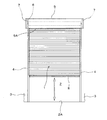
以下に本発明を実施するための形態を図面に基づいて説明する。図1は、本発明の一実施形態に係るシャッター装置の全体正面図であり、このシャッター装置は、車庫用シャッター装置である。 EMBODIMENT OF THE INVENTION Below, the form for implementing this invention is demonstrated based on drawing. FIG. 1 is an overall front view of a shutter device according to an embodiment of the present invention, and this shutter device is a garage shutter device.
このシャッター装置は、上下方向を開閉移動方向とするシャッターカーテン1を有し、このシャッターカーテン1は、建物である車庫の開口部となっている出入口2を開閉し、このシャッターカーテン1の幅方向の両端部である左右方向の両端部は、出入口2の左右両側の壁等の建物躯体3に取り付けられているガイドレール4の内部に挿入され、これらのガイドレール4に案内されてシャッターカーテン1は上下に開閉移動する。出入口2の上側の壁等の建物躯体にはシャッターケース5が取り付けられ、このシャッターケース5の内部において、巻取軸6が左右一対のブラケット7に回転自在に支持されており、この巻取軸6に、シャッターケース5の下面5Aに形成されているスリットを通過してシャッターケース5の内部に達しているシャッターカーテン1の上端部が結合されているため、正逆回転自在となっている巻取軸6によるシャッターカーテン1の巻き取りと繰り出しにより、シャッターカーテン1は、ガイドレール4に案内されて上下方向に開閉移動する。
This shutter device has a
図1のシャッター装置は、シャッターカーテン1の最下端部を構成している座板8に係合させる操作棒等により、シャッターカーテン1に上下方向の移動荷重を付与することによってシャッターカーテン1が開閉移動する手動式シャッター装置である。巻取軸6には、シャッターカーテン1が下方へ閉じ移動することで正回転する巻取軸6によって戻しばね力が蓄圧される戻しばねが設けられているため、巻取軸6が逆回転することで行われるシャッターカーテン1の上方への開き移動は、この戻しばねの戻しばね力が補助力となって行われるようになっている。そして、シャッターカーテン1の座板8がシャッターケース5の下面5Aに達するシャッターカーテン1の全開時には、戻しばねのばね力によりシャッターカーテン1は全開状態を維持し、座板8が出入口2の床2Aに達するシャッターカーテン1の全閉時には、戻しばねの上記戻しばね力よりも、巻取軸6から繰り出されたシャッターカーテン1の重量による下向き荷重が大きくなるため、シャッターカーテン1は全閉状態を維持するようになっている。
The shutter device of FIG. 1 opens and closes the
なお、本実施形態では、座板8についてのシャッターカーテン1の幅方向の長さが、左右一対のガイドレール4の内幅寸法と同じ又はこの内幅寸法よりも小さくなっており、このため、座板8の長さ方向両端部はガイドレール4の内部に挿入されていない。
In the present embodiment, the length in the width direction of the
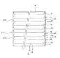
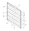
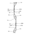
図2には、巻取軸6に巻き取られる以前のシャッターカーテン1の展開された全体正面図が示されており、図3は、このシャッターカーテン1の右側面図である。また、図4は、シャッターカーテン1の主要部を形成する要素となっているパネル10の正面図であり、図5は、このパネル10の右側面図、図6は、パネル10の斜視図である。図2及び図3に示されているように、シャッターカーテン1は、シャッターカーテン1の開閉移動方向である上下方向に複数のパネル10と1個の座板8とを連設したものであり、図2に示されているように、シャッターカーテン1の幅寸法と同じ左右方向の幅寸法を有しているそれぞれのパネル10は、シャッターカーテン1の開閉移動方向の長さ寸法が、図3の一定値のHとなっているものである。
FIG. 2 shows a developed front view of the
図4〜図6から分かるように、パネル10は、平面状板材である金属製の薄板を折り曲げ装置等により交互に折り曲げ、これにより、シャッターカーテン1の厚さ方向に凹凸となった凹部11と凸部12をシャッターカーテン1の開閉移動方向に連続させたものである。このため、パネル10には、前述した車庫の内部側に窪んだ複数の凹部11と、車庫の外部側に突出した複数の凸部12が設けられており、これらの凹部11と凸部12は、シャッターカーテン1の幅方向全長に渡って連続して形成されているため、パネル10は、同一の縦断面形状がシャッターカーテン1の幅方向全長に連続したものになっている。そして、本実施形態のそれぞれ複数個の凹部11と凸部12は、シャッターカーテン1の厚さ方向への成分がない又は殆どない平面状のものになっている。
As can be seen from FIGS. 4 to 6, the
なお、パネル10を車庫の内側で見た場合には、凹部12は凸部であり、また、凸部12は凹部である。また、パネル10の材料である金属製の薄板は、例えば、厚さ寸法が0.6mmのステンレス、又はスチール、又はアルミ、又は亜鉛メッキ鋼板等である。
In addition, when the
図7は、図5の一部拡大図であり、この図7に示されているように、凹部11と凸部12を繋いでいる繋ぎ部13は、シャッターカーテン1の厚さ方向と平行又は略平行の水平部又は略水平部となっており、また、凹部11と繋ぎ部13との接続箇所及び凸部12と繋ぎ部13との接続箇所は、直角又は略直角の屈曲部となっている。
FIG. 7 is a partially enlarged view of FIG. 5. As shown in FIG. 7, the connecting
図5に示されているように、パネル10におけるシャッターカーテン1の開閉移動方向の一方の端部、すなわち、それぞれのパネル10の上端部近傍は、凹部11と凸部12のうちの一方、本実施形態では凹部11になっており、この凹部11の上先端部に、下向きに開口した第1フック部14が設けられ、それぞれのパネル10の下端部近傍は、凹部11と凸部12のうちの他方、本実施形態では凸部12になっており、この凸部12の下先端部に、上向きに開口した第2フック部15が設けられている。パネル10の上端部に設けられた上端フック部となっている第1フック部14は、上記凹部11の上向きの延長部となっている基部14Aと、この基部14Aの先端からシャッターカーテン1の厚さ方向のうち、凸部12の張り出し側と同じ側へ水平又は略水平に屈曲した屈曲部14Bと、この屈曲部14Bの先端から下向きに延出した下向き延出部14Cとにより形成されている。また、パネル10の下端部に設けられた下端フック部となっている第2フック部15は、上記凸部12の下向きの延長部となっている基部15Aと、この基部15Aの先端からシャッターカーテン1の厚さ方向のうち、凹部11の窪み側と同じ側へ水平又は略水平に屈曲した屈曲部15Bと、この屈曲部15Bの先端から上向きに延出した上向き延出部15Cとにより形成されている。
As shown in FIG. 5, one end portion of the
このような第1フック部14と第2フック部15は、シャッターカーテン1の幅方向全長に渡って連続して設けられている。
The
図4及び図6に示されているように、それぞれのパネル10には、シャッターカーテン1の幅方向両端部において、ベルト部材21が取り付けられ、図4及び図6で示されているパネル10の面は、シャッターカーテン1の厚さ方向の両側の面のうち、前述した車庫の外部側の面であるため、シャッターカーテン1の開閉移動方向である上下方向への延設長さを有しているベルト部材21は、パネル10における車庫の外部側の面に設けられた第1ベルト部材21である。また、図5及び図7に示されているように、パネル10における車庫の内部側の面には、第1ベルト部材21と同様に、シャッターカーテン1の開閉移動方向である上下方向への延設長さを有している第2ベルト部材22が設けられている。この第2ベルト部材22も、それぞれのパネル10におけるシャッターカーテン1の幅方向両端部に取り付けられており、第1ベルト部材21のパネル10における取付位置と、第2ベルト部材22のパネル10における取付位置は、シャッターカーテン1の幅方向において、一致又は略一致している。
As shown in FIGS. 4 and 6,
なお、第1ベルト部材21と第2ベルト部材22は、シャッターカーテン1が図1で示されている左右のガイドレール4に案内されて開閉移動するときに、それぞれ金属製となっているシャッターカーテン1とガイドレール4が直接接触することを防止し、これよって消音するための接触防止部材である。
The
本実施形態において、パネル10への第1及び第2ベルト部材21,22の取り付けは、シャッター装置が製造される工場で行われており、また、この取り付けは、パネル10と第1及び第2ベルト部材21,22を貫通する止め具となっているステープル23の打ち込みにより行われ、パネル10への第1及び第2ベルト部材21,22の取り付けを、ステープル23を用いずに、接着剤により行ってもよい。
In the present embodiment, the first and
本実施形態におけるパネル10への第1及び第2ベルト部材21,22の取り付けは、パネル10に形成されている凹部11と凸部12とにおいて行われているため、これらのベルト部材21,22は、凹部11と凸部12の形状に倣ってシャッターカーテン1の厚さ方向に蛇行しながら上下方向へ延びている。
Since the first and
このため、第1ベルト部材21は、凹部11において、この凹部11の形状にしたがってシャッターカーテン1の厚さ方向であるパネル10の厚さ方向に折り曲げられており、また、第2ベルト部材22も、パネル10を車庫の内側で見た場合に凹部となっている凸部12において、この凸部12の形状にしたがってパネル10の厚さ方向に折り曲げられている。
Therefore, the
そして、第1及び第2ベルト部材21,22は、パネル10のそれぞれ複数個の凹部11と凸部12に渡る長さ寸法を有している。
The first and
第1及び第2ベルト部材21,22の材料は、例えば、耐摩耗性を有する布又はこの布に耐摩耗性を有する合成樹脂を含浸させたものである。本実施形態では、図7に示されているように、ステープル23における第1ベルト部材21側のベース部23Aは、第1ベルト部材21の表面から僅かに突出し、ステープル23における第2ベルト部材22側の折り曲げ部23B,23Cも、第2ベルト部材22の表面から僅かに突出しているが、パネル10への第1及び第2ベルト部材21,22の取り付けを、これらのベルト部材21,22について共通の止め具となっているステープル23の打ち込みにより行う際に、ステープル23の打ち込み荷重を大きくすることにより、ステープル23が配置された箇所での第1及び第2ベルト部材21,22の表面を凹ませ、これにより、ステープル23における第1ベルト部材21側のベース部23Aと、ステープル23における第2ベルト部材22側の折り曲げ部23B,23Cとを、ステープル23が配置されていない箇所でのベルト部材21,22の表面よりもパネル10の近い位置に位置させるようにしてもよい。
The material of the first and
この説明から分かるように、本実施形態では、シャッターカーテン1の厚さ方向となっているパネル10の厚さ方向の両側の面に配置されている第1ベルト部材21と第2ベルト部材22は、パネル10を貫通した止め具であるステープル23により共締め状態でパネル10に取り付けられており、このため、パネル10への第1及び第2ベルト部材21,22の取付作業をシャッター装置が製造される工場で容易に行える。
As can be seen from this description, in the present embodiment, the
なお、本実施形態では、図5に示されているように、第1ベルト部材21は、パネル10の上下両端部に設けられている第1及び第2フック部14,15を除く、パネル10の上下方向の略全長に渡って延設されており、第2ベルト部材22は、パネル10の上下両端部の第1及び第2フック部14,15と、第2フック部15の上側の凹部11(第2ベルト部材22側からすると凸部)とを除く、パネル10の上下方向の大部分に延設されているが、第2ベルト部材22を、第1ベルト部材21と同様に、パネル10の上下両端部の第1及び第2フック部14,15を除く、パネル10の上下方向の略全長に渡って延設してもよい。
In the present embodiment, as shown in FIG. 5, the
図8には、シャッターカーテン1の開閉移動方向に連設された上下2個のパネル10同士の連結構造の拡大図が示されており、図9には、この連結構造を分解した状態が示されている。上下2個のパネル10同士を連結する際には、はじめに、上側のパネル10の下端部に上向きに開口していて、前述の下端フック部となっている第2フック部15と、下側のパネル10の上端部に下向きに開口していて、前述の上端フックとなっている第1フック部14とを、下側のパネル10を持ち上げて下に降ろすことにより、互いに上下に嵌合させる。次いで、上下2個のパネル10同士を連結するための連結手段であって、パネル10同士を止着するための止着具にもなっているリベット24のうち、頭部24Aから水平方向に延出している軸部24Bを、第1フック部14の前述の基部14Aと、第2フック部15の上向き延出部15Cとに予め形成されている孔に、前述した車庫の内部側から外部側へ貫通させ、軸部24Bのうち、これらの孔からシャッターカーテン1の厚さ方向に突出した先端部に、水平方向に作用させた圧縮荷重により、図8で示されている突出部24Cを圧縮膨出させて形成する。
FIG. 8 shows an enlarged view of a connection structure between two upper and
なお、リベット24は、頭部24A側からの作業により、軸部24Bの先端部に突出部24Cを圧縮膨張形成することができるブラインドリベットである。
The
これにより、上下2個のパネル10同士は連結されることになり、この連結は、リベット24の軸部24Bが貫通部となって貫通する第1フック部14の基部14Aと第2フック部15の上向き延出部15Cとが、これらのパネル10の連結箇所となることにより行われる。
As a result, the two upper and
上記連結手段であって、上記止着具でもあるリベット24による上下2個のパネル10同士の連結は、シャッターカーテン1の幅方向の複数箇所において行われ、また、このような連結作業が、シャッターカーテン1を構成するそれぞれのパネル10について行われることにより、座板8を除くシャッターカーテン1の主要部が形成されることになる。
The two upper and
なお、上記連結手段でもある上記止着具を、リベット24とせず、ビスとしてもよい。ビスとする場合には、第2フック部15の上向き延出部15Cに、バーリング加工による筒部を形成し、この筒部の内周面に、ビスを螺合させるための雌ねじを刻設する。
Note that the fastening device, which is also the connecting means, may be a screw instead of the
本実施形態では、後述するように、シャッターカーテン1の主要部を形成するそれぞれのパネル10をリベット24で連結することは、シャッター装置が製造される工場では行われず、シャッター装置の設置施工作業が行われる現場において行われる。
In this embodiment, as will be described later, connecting each
図10には、シャッターカーテン1の主要部を形成するそれぞれのパネル10のうち、最下段のパネル10に座板8を取り付けるための構造が示されている。座板8は、パネル10よりも厚さ寸法が大きい金属製のベース部材30と、このベース部材30におけるシャッターカーテン1の厚さ方向両側に、水平部31B,32Bをシャッターカーテン1の厚さ方向の互いに反対側の向きにして鉛直部31A,32Aが配置された2個の金属製アングル部材31,32とからなり、ベース部材30とアングル部材31,32は、ビス33及びナット34により結合されている。
FIG. 10 shows a structure for attaching the
ベース部材30の上端部には、基部35Aと、この基部35Aの先端からシャッターカーテン1の厚さ方向のうち、パネル10の凸部12の張り出し側と同じ側へ水平又は略水平に屈曲した屈曲部35Bと、この屈曲部35Bの先端から下向きに延出した下向き延出部35Cとにより、下向きに開口したフック部35が形成されており、このフック部35の形状は、パネル10の上端部に形成されている第1フック部14の形状と同じである。
At the upper end portion of the
最下段のパネル10に座板8を取り付けるためには、最下段のパネル10の下端部に上向きに開口して形成されている第2フック部15と、座板8の上端部に下向きに開口して形成されているフック部35とを、座板8を持ち上げて下に降ろすことにより、互いに上下に嵌合させ、次いで、最下段のパネル10と座板8とを連結するための連結手段であって、パネル10に座板8を止着するための止着具にもなっているリベット36のうち、頭部36Aから水平方向に延出している軸部36Bを、フック部35の基部35Aと第2フック部15の上向き延出部15Cとに予め形成されている孔に前述した車庫の内部側から外部側へ貫通させ、この後に、前述したリベット24の場合と同様に、軸部36Bのうち、これらの孔からシャッターカーテン1の厚さ方向に突出した先端部に、水平方向に作用させた圧縮荷重により、突出部36Cを圧縮膨出させて形成する。したがって、このリベット36もブラインドリベットである。
In order to attach the
これにより、最下段のパネル10に座板8が取り付けられ、リベット36による最下段のパネル10への座板8の取付作業は、シャッターカーテン1の幅方向の複数箇所において行われる。
Accordingly, the
図11には、図1のシャッター装置の設置現場において、それぞれのパネル10をシャッターカーテン1の開閉移動方向に連結することにより、シャッターカーテン1を形成するための作業が示されている。
FIG. 11 shows an operation for forming the
車庫の出入口2の左右両側の壁等の建物躯体3にガイドレール4を取り付ける以前であって、出入口2の上側の壁等の建物躯体に図1のシャッターケース5を取り付ける以前において、出入口2の上側の壁等の建物躯体に取り付けた左右一対のブラケット7に巻取軸6を回転自在に支持させ、梯子等により巻取軸6の近く達した作業者は、シャッターカーテン1の主要部を形成するためにシャッターカーテン1の開閉移動方向に連設される複数のパネル10のうち、最上段のパネル10の上端部の第1フック部14を巻取軸6の外周にビスやリベット等の結合具により結合し、この後に、作業者は、巻取軸6を逆回転させることにより、最上段のパネル10のうち、下端部の第2フック部15及びこの第2フック部15よりも少し上側部分を、巻取軸6に巻き取られていない巻き残し箇所にして、最上段のパネル10の大部分を巻取軸6で巻き取る。
Before the
次いで、作業者は、上から2段目のパネル10を持ち上げて、このパネル10の上端部の第1フック部14を最上段のパネル10の下端部の第2フック部15に上から嵌合し、そして、これらのパネル10同士を、前述したようにリベット24により連結する。この後に、作業者は、巻取軸6を再度逆回転させ、これにより、上から2段目のパネル10のうち、下端部の第2フック部15及びこの第2フック部15よりも少し上側部分を、巻取軸6に巻き取られていない巻き残し箇所にして、上から2段目のパネル10の大部分を巻取軸6で巻き取る。
Next, the operator lifts the second-
これ以後、作業者が、上から3段目のパネル10及びこのパネル10よりもさらに下側のパネル10について、上述と同じ連結作業を繰り返すことにより、座板8を除くシャッターカーテン1の主要部が、巻取軸6で巻き取られながらシャッター装置の設置現場において形成されることになり、最下段のパネル10についての連結作業が終了した後に、このパネル10の下端部の第2フック部15に、前述した作業により座板8を取り付ける作業を行う。
Thereafter, the operator repeats the same connecting operation as described above for the
このように最下段のパネル10の下端部の第2フック部15に座板8を取り付けた後に、作業者は、さらに巻取軸6を、この巻取軸6に巻回されているパネル10を介して逆回転させ、これにより、座板8が出入口2の上端部を越えた高さ位置に達した後に、これを言い換えると、座板8が図1で示した左右一対のガイドレール4の上端部を越えた高さ位置に達した後に、出入口2の左右両側の壁等の建物躯体3にこれらのガイドレール4を取り付ける作業を行う。次いで、作業者が巻取軸6を正回転させることにより、巻取軸6からシャッターカーテン1を繰り出し、これにより、最下段のパネル10から、それぞれのパネル10の幅方向両端部を左右のガイドレール4の内部に挿入する作業を行い、これにより、シャッターカーテン1は、左右のガイドレール4に案内されて上下方向に開閉移動自在となる。
After attaching the
この後に、出入口2の上側の壁等の建物躯体に図1で示したシャッターケース5を取り付ける作業などの残余の作業を行う。
Thereafter, the remaining work such as the work of attaching the
以上の作業により形成されるシャッターカーテン1の主要部は、それぞれに第1及び第2ベルト部材21,22が取り付けられた複数のパネル10によって形成されており、それぞれの第1ベルト部材と、それぞれの第2ベルト部材22は、シャッターカーテン1の開閉方向に直線的に並んでいるとともに、パネル10同士の連結箇所には、第1及び第2ベルト部材21,22が配置されていない。
The main part of the
なお、前述したように、座板8についてのシャッターカーテン1の幅方向の長さは、左右一対のガイドレール4の内幅寸法と同じ又はこの内幅寸法よりも小さくなっており、座板8の長さ方向両端部はガイドレール4の内部に挿入されていないため、最下段のパネル10に座板8を取り付ける作業を、上述のようにシャッター装置の設置現場で行うのではなく、例えば、シャッター装置を製造する工場等において予め行ってもよい。
As described above, the length in the width direction of the
また、座板8を、この座板8の長さ方向両端部のうちの少なくとも一部が、例えば、図10で示されている座板8を構成しているベース部材30の長さ方向両端部が、ガイドレール4の内部に挿入されるものとしてもよい。このように座板8の長さ方向両端部のうちの少なくとも一部をガイドレール4の内部に挿入するようにする場合には、座板8を除くシャッターカーテン1の主要部がそれぞれのパネル10の連結作業により形成された後に、最下段のパネル10に座板8を取り付け、次いで、作業者が巻取軸6を逆回転させて座板8が出入口2の上端部を越えた高さ位置に達した後に、出入口2の左右両側の壁等の建物躯体3にガイドレール4を取り付ける作業を行い、次いで、作業者が巻取軸6を正回転させることにより、座板8からガイドレール4の内部に挿入する作業を行うようにしてもよい。
Further, at least a part of the
なお、巻取軸6を回転自在に支持する左右一対のブラケット7の下面に、シャッターカーテン1を上下に挿通させるスリットが設けられたまぐさ部材が取り付けられ、左右のガイドレール4の上端部がこのスリットに挿入されてまぐさ部材よりも高い位置に達していて、座板8がまぐさ部材を越えない高さ位置まで達するようになっている場合には、それぞれのガイドレール4を鉛直方向に対し少し傾けることにより、ガイドレール4の上端部を上記スリットに挿入して、この上端部の位置をまぐさ部材よりも高い位置とし、次いで、ガイドレール4を鉛直方向に直立した状態にする作業を行うとともに、このような作業を行うときに、シャッターカーテン1の下端部、言い換えると、前述したように、座板8についてのシャッターカーテン1の幅方向の長さが左右一対のガイドレール4の内幅寸法と同じ又はこの内幅寸法よりも小さくなっているために、ガイドレール4の内部のガイド溝に座板8の長さ方向両端部が挿入されていないようになっている場合には、ガイドレール4の内部のガイド溝に最下段のパネル10を挿入する作業を行うようにし、また、ガイドレール4の内部のガイド溝に、前述したように、座板8の長さ方向両端部のうちの少なくとも一部が挿入されるようになっている場合には、上記作業を行うときに、ガイドレール4の内部のガイド溝に座板8の長さ方向両端部のうちの少なくとも一部を挿入する作業を行うようにする。
A lintel member provided with a slit through which the
以上説明した本実施形態に係るシャッターカーテン1は、シャッターカーテン厚さ方向に凹凸となっている凹部11と凸部12がシャッターカーテン1の開閉移動方向に並設され、開閉移動方向に連続しているこれらの凹部11と凸部12がそれぞれ複数設けられているものとなっているが、座板8を除くシャッターカーテン1の部分は、言い換えると、シャッターカーテン1の主要部は、複数のパネル10がシャッターカーテン1の開閉移動方向に連設されることにより形成されており、これらのパネル10のそれぞれに複数の凹部11と複数の凸部12が設けられているとともに、シャッターカーテン1の開閉移動方向に隣接しているパネル10同士が連結手段であるリベット24により連結されているため、パネル10同士をリベット24で連結する作業を、シャッター装置の設置現場で行うことができ、これにより、シャッター装置が製造される工場からシャッター装置の設置現場までシャッターカーテン1を搬送する際や、保管しておく際に、シャッターカーテン1の構成部材となっているそれぞれのパネル10を分離しておくことができ、このため、シャッターカーテン1を巻回しておく必要はなくなり、それぞれのパネル10を平積みしたり、縦置きにして厚さ方向に並べたりすることにより、搬送や保管を行うことができるため、その取り扱いが容易になる。
In the
また、パネル10同士を連結する連結手段は、リベット24であり、このリベット24は、ドリル等の工具により破壊して取り除き可能となっているため、連結手段は、連結解除可能となっている手段になっている。このため、シャッターカーテン1の開閉移動方向に複数個がリベット24で連結されているパネル10のうち、損傷等したパネル10が生じても、損傷等したパネル10だけを、リベット24による連結を解除することにより取り外し、このパネル10を新たなパネル10に交換して、この新たなパネル10を、交換されないパネル10にリベット24により連結することができ、このため、シャッターカーテン1のメンテナンス作業等を容易に行える。
The connecting means for connecting the
なお、損傷等したパネル10を新たなパネル10に交換するために、リベット24を破壊して取り除いても、下側のパネル10の第1フック部14と上側のパネル10の第2フック部15が互いに上下に当接係合するため、これらのパネル10同士の連結状態を維持することができ、このため、下側のパネル10が落下して破損するなどの事態が生ずることはない。
Even if the
また、第1及び第2ベルト部材21,22はパネル10ごとに設けられているため、これらのベルト部材21,22のパネル10への取付作業をシャッター装置が製造される工場でパネル10ごとに行えることになり、このため、ベルト部材21,22の取付作業の容易化を図ることができる。さらに、それぞれのパネル10に第1及び第2ベルト部材21,22を取り付ける作業は、上記工場で行われるため、シャッター装置の設置現場において、それぞれのパネル10をシャッターカーテン1の開閉移動方向に連結することにより、自ずとこのシャッターカーテン1を、第1及び第2ベルト部材21,22を備えたものにすることができる。
In addition, since the first and
また、図3及び図5で示したパネル10についてのシャッターカーテン1の開閉移動方向の長さ寸法Hは、リベット24やリベット36により、他のパネル10が連結されたり、座板8が取り付けられたりする上下の箇所の間の長さ寸法であり、この長さ寸法Hは、それぞれのパネル10についての一定値になっており、さらに、それぞれのパネル10の上端部に第1フック部14が設けられ、下端部に第2フック部15が設けられ、幅方向両端部に第1及び第2ベルト部材21,22が取り付けている点や、凹部11の個数がそれぞれのパネル10について同じになっている点、凸部12の個数がそれぞれのパネル10について同じになっている点において、これらのパネル10は同じ形状及び構造になっているため、シャッターカーテン1の開閉移動方向に連設されることでシャッターカーテン1の主要部を形成するためのそれぞれのパネル10を、寸法や形状、構造が同じになったユニット化して製造できることになり、このため、これらのパネル10の規格化により、多数のパネル10を安価に製造できる。
Further, the length H in the opening / closing movement direction of the
また、本実施形態では、それぞれのパネル10に設けられている凹部11のシャッターカーテン1の開閉移動方向の幅寸法は同じ又は略同じであるとともに、それぞれのパネル10に設けられている凸部12のシャッターカーテン1の開閉移動方向の幅寸法も同じ又は略同じであり、このため、それぞれのパネル10に折り曲げ装置等により凹部11と凸部12を形成するための作業を容易に行え、この点でもパネル10の製造コストを低減化できる。
Further, in the present embodiment, the width dimensions of the
また、長さ寸法が一定値のHとなっているパネル10の連結個数を選択することにより、出入口2の高さ寸法の違いが長さ寸法Hよりも大きくなっているそれぞれのシャッター装置の施工現場に対処できるとともに、出入口2の高さ寸法の違いが長さ寸法Hより小さくなっているそれぞれのシャッター装置の施工現場については、シャッターカーテン1が全閉となったときにおける巻取軸6でのシャッターカーテン1の捨て巻き量を異ならせることにより、これらの施工現場にも対処できるようになる。
Further, by selecting the number of
さらに本実施形態によると、シャッターカーテン1の開閉移動方向に連設される上下2個のパネル10同士は、図8及び図9で説明したように、リベット24の軸部24Bが貫通部となって貫通する下側のパネル10の第1フック部14の基部14Aと、上側のパネル10の第2フック部15の上向き延出部15Cとがこれらのパネル10の連結箇所となることにより、連結されることになり、上記貫通部となっている軸部24Bは、頭部24Aからシャッターカーテン1の厚さ方向である水平方向又は略水平方向に延びているため、この軸部24Bが、シャッターカーテン1の厚さ方向の成分を有してパネル10同士の連結箇所を貫通しているが、リベット24で連結される上下2個のパネル10には、下側のパネル10の第1フック部14の下向き延出部14Cと、上側のパネル10の第2フック部15の基部15Aとが設けられており、これらの下向き延出部14Cと基部15Aは、貫通部となっている軸部24Bのうち、パネル10同士の連結箇所からシャッターカーテン1の厚さ方向の成分を有して突出している突出部24Cを、この突出部24Cをシャッターカーテン1の厚さ方向に越えた位置で覆うための覆い部となっているため、突出部24Cが、シャッターカーテン1の開閉移動時等において、シャッターカーテン1の外部のものに接触することを、これらの覆い部により防止することができ、また、巻取軸6によるシャッターカーテン1の巻き取り、繰り出しを所定通り行える。
Furthermore, according to the present embodiment, as described in FIGS. 8 and 9, the two upper and
また、リベット24の頭部24Aについての下側のパネル10の第1フック部14の基部14Aからの突出量は、小さいため、シャッターカーテン1の開閉移動時等において、頭部24Aがシャッターカーテン1の外部のものに接触するおそれもない。
Further, since the protruding amount from the
図2には、複数のパネル10の連結と座板8の取り付けとにより形成されたシャッターカーテン1の展開正面図が示されているとともに、この図2には、シャッターカーテン1の開閉移動を案内するための左右一対のガイドレール4が二点鎖線で示されている。それぞれのパネル10の幅方向両側部において、シャッターカーテン1の厚さ方向の両側の面に設けられている前述の第1及び第2ベルト部材21,22は、シャッターカーテン1のうち、左右一対のガイドレール4の内部に挿入される箇所に配置されている。
FIG. 2 shows a developed front view of the
図12には、シャッターカーテン1の幅方向両端部が左右一対のガイドレール4の内部に挿入されてシャッターカーテン1が開閉移動するときの平断面図が示されている。左右一対のガイドレール4の内部に挿入されているシャッターカーテン1の幅方向両端部には、第1及び第2ベルト部材21,22が取り付けられているため、シャッターカーテン1がこれらのガイドレール4に案内されて上下に開閉移動する際に、シャッターカーテン1とガイドレール4の内面とが直接接触することは、接触防止部材となっているベルト部材21,22によって防止され、このため、シャッターカーテン1とガイドレール4の内面とが直接接触することによって生ずる摩擦音等の異音の発生をなくすことができる。
FIG. 12 shows a plan sectional view when the
また、第1及び第2ベルト部材21,22は、ガイドレール4の内面ではなく、シャッターカーテン1を構成するパネル10の外面に取り付けられているため、工場で行うパネル10への第1及び第2ベルト部材21,22の取付作業を容易に行える。
Further, since the first and
なお、本実施形態のようにシャッターカーテン1の構成部材となっているそれぞれのパネル10に第1及び第2ベルト部材21,22がステープル23で取り付けられていても、前述したように、ステープル23の打ち込み荷重を大きくすることにより、ステープル23が配置された箇所での第1及び第2ベルト部材21,22の表面を凹ませ、これにより、ステープル23における第1ベルト部材21側のベース部23Aと、ステープル23における第2ベルト部材22側の折り曲げ部23B,23Cとを、ステープル23が配置されていない箇所でのベルト部材21,22の表面よりもパネル10の近い位置に位置させることにより、ステープル23のベース部23Aと折り曲げ部23B,23Cがガイドレール4の内面に接触せず、ガイドレール4の内面に第1及び第2ベルト部材の表面を接触させることができる。
Even if the first and
また、パネル10への第1及び第2ベルト部材21,22の取り付けを接着剤で行うことによっても、ガイドレール4の内面に第1及び第2ベルト部材21,22の表面を接触させることができる。
Further, the surfaces of the first and
図13の実施形態では、シャッターカーテン1の幅方向両端部において、シャッターカーテン1の厚さ方向の両側の面にベルト部材を取り付けず、シャッターカーテン1の開閉移動方向への長さを有するベルト部材21を、シャッターカーテン1の厚さ方向の両側の面のうち、一方の面となっている前述の車庫の外部側の面だけに取り付け、他方の面となっている車庫の内部側の面には、ベルト部材を取り付けていない。そして、この図13の実施形態では、左右一対のガイドレール4の内面のうち、シャッターカーテンの厚さ方向の上記他方の面と対面する面には、シャッターカーテン1の開閉移動方向への長さを有するベルト部材40が取り付けられている。
In the embodiment of FIG. 13, the belt member having a length in the opening / closing movement direction of the
この実施形態でも、シャッターカーテン1の厚さ方向の両側の面と、ガイドレール4の内面とが直接接触することをベルト部材21とベルト部材40により防止しながら、シャッターカーテン1を左右一対のガイドレール4に案内させて上下に開閉移動させることができる。
In this embodiment as well, the
特に、この実施形態のシャッターカーテン1については、シャッターカーテン1の厚さ方向の片側の面だけにベルト部材21が取り付けられているため、シャッターカーテン1が巻取軸6で巻き取られたときのシャッターカーテン1の巻径を小さくすることができ、これにより、図1で示したシャッターケース5の上下寸法を小さくできるなどの効果を得られる。
In particular, with respect to the
図14は、パネル10に設けられる凹部11と凸部12を繋いでいる繋ぎ部について別実施形態を示す。この実施形態における凹部11の下端と凸部12の上端とを繋いでいる繋ぎ部13’は、下方への傾斜角度をもって前述の車庫の内部側から外部側へ延びており、凸部12の下端と凹部11の上端とを繋いでいる繋ぎ部13’’は、下方への傾斜角度をもって車庫の外部側から内部側へ延びている。このため、凹部11と繋ぎ部13’,13’’との接続箇所及び凸部12と繋ぎ部13’,13’’との接続箇所は、直角又は略直角の屈曲部とはなっていない。
FIG. 14 shows another embodiment of the connecting portion connecting the
この実施形態によると、それぞれのパネル10に凹部11と凸部12を交互に形成するために行う折り曲げ加工を、上記接続箇所が直角又は略直角の屈曲部とはなっていない分だけ容易に行えるようになり、また、巻取軸6によるシャッターカーテン1の巻き取りを一層確実に行えるようになる。
According to this embodiment, the bending process performed to alternately form the
さらに、第1ベルト部材21が取り付けられているシャッターカーテン1の厚さ方向の一方の面は、車庫の外部側の面となっているが、凹部11の下端と凸部12の上端とを繋いでいる繋ぎ部13’は、下方への傾斜角度をもって車庫の内部側から外部側へ延びていて、水勾配を有しているため、この繋ぎ部13’に、車庫の外部側で降った雨水等が溜まることを防止することができる。
Furthermore, one surface in the thickness direction of the
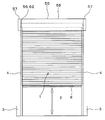
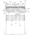
図15で示した実施形態に係る車庫用シャッター装置でも、シャッターカーテン1は、左右一対のガイドレール4に案内されて建物である車庫の開口部となっている出入口2を開閉し、シャッターカーテン1は、シャッターケース55の内部に配置された正逆回転する巻取軸56による巻き取り、繰り出しにより上下に開閉移動するが、巻取軸56は電動式巻取軸となっているため、図15のシャッター装置は、電動式の車庫用シャッター装置である。この電動式シャッター装置のシャッターケース55は、巻取軸56を支持する左右一対のブラケット57と、これらのブラケット57に架け渡し配設されて巻取軸56の前後や上下を覆うカバー部材58とを有するものになっている。
Also in the garage shutter device according to the embodiment shown in FIG. 15, the
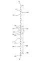
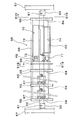
図16には、巻取軸56にシャッターカーテン1の上端部を結合する以前であって、カバー部材58が取り外されている状態が示されている。また、図17には、図16で示されている巻取軸56の拡大図が示されており、図18は、図17のS18−S18線断面図である。巻取軸56は、左右一対のブラケット57に設けられた軸受け部60により両端部がボルト、ナット等による結合具61で回転不能に支持された中心軸62と、この中心軸62の外周に、中心軸62を中心に回転自在に配設された回転体63とからなり、後述する吊元部材を介してシャッターカーテン1の上端が連結されるこの回転体63は、それぞれが中心軸62に対して軸受け部材64により回転自在となっていて、側面視が円形となっている複数個のホイール部材65と、シャッターカーテン1の幅方向となっている中心軸62の軸方向に間隔をあけて並設されているこれらのホイール部材65を連結している棒状の連結部材66とからなる。
FIG. 16 shows a state in which the
中心軸62と回転体63との間には、コイルスプリングによる複数個の戻しばね67が架け渡されており、これらの戻しばね67の一端は中心軸62に連結され、他端はホイール部材65に連結されているため、シャッターカーテン1を繰り出すときの回転体63の正回転時に、戻しばね67には戻しばね力が蓄圧され、シャッターカーテン1を巻き取るときの回転体63の逆回転時に、この戻しばね力により、回転体63の逆回転が補助されるようになっている。
A plurality of return springs 67 by coil springs are bridged between the
図17には、巻取軸56を正逆回転させるための駆動装置70、言い換えると、中心軸62を中心に回転体63を正逆回転させるための駆動装置70も示されている。この駆動装置70は、図18に示されているように、複数本の連結部材66が嵌合された凹部71Aが形成されていて、内歯歯車となっている回転歯車71と、図17に示されているように、この回転歯車71を回転させるための駆動軸72を有する駆動装置本体73とを含んで構成され、駆動軸72にクラッチ68を介して連結されていて、回転歯車71の内歯71B(図18を参照)に噛合しているピニオン69が、駆動軸72により正逆回転することにより、回転歯車71が正逆回転し、これにより、回転体63が、言い換えると、巻取軸56が正逆回転するようになっている。電動モータとブレーキ手段との組み合せで構成されている駆動装置本体73は、制御装置74により駆動制御され、このように駆動装置本体73を制御装置74により駆動制御するための信号は、車庫の壁に取り付けられている図示外の操作装置から、無線信号又は図示外の電気配線により制御装置74に送信される。
FIG. 17 also shows a
なお、図17で示されているクラッチ68は、図示外のワイヤー等の紐状操作部材の引っ張り操作により、巻取軸56の外部からオン、オフの切り替え操作を行えるようになっている。
Note that the clutch 68 shown in FIG. 17 can be switched on and off from the outside of the winding
図17に示されている駆動装置本体73と制御装置74は、図18に示されているブラケット75により中心軸62の外周に取り付けられ、このブラケット75には、回転歯車71に形成されている図18のリング状溝71Cに嵌合した複数個のローラ76が回転自在に取り付けられており、回転歯車71は、これらのローラ76により支持されて正逆回転し、これにより、回転体63も正逆回転する。
The drive device
また、図17に示されているように、駆動装置70は、回転歯車71の正逆回転数をカウントするロータリ式エンコーダ77を備えており、上記操作装置の操作により、回転歯車71が回転し、回転体63も回転してシャッターカーテン1が開閉移動し、このシャッターカーテン1が全閉位置や全開位置に達したことがエンコーダ77により検出されると、このエンコーダ77から制御装置74に送られる信号により、制御装置74は、駆動装置本体73の電動モータを停止させてブレーキ手段をオンとし、シャッターカーテン1を停止させる。
Further, as shown in FIG. 17, the driving
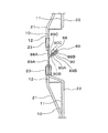
図19は、図17のS19−S19線断面図であり、この図19には、巻取軸56の中心軸62を回転不能に支持するための軸受け部60を備えているブラケット57の側面図が示されており、図15及び図16に示されているように、左右一対設けられているブラケット57は、図19において、左右対称の形状となっているため、図19のブラケット57は、左右一対のブラケット57のうち、図15及び図16における右側のブラケットである。
FIG. 19 is a cross-sectional view taken along line S19-S19 in FIG. 17. In FIG. 19, a side view of a
図19に示されているように、それぞれのブラケット57の底部には、シャッターカーテン1の厚さ方向に間隔をあけて配置されるまぐさ部材78,79を取付載置するための取付部57A,57Bが設けられ、左右のブラケット57間に渡るシャッターカーテン1の幅方向の長さを有するこれらのまぐさ部材78,79の間に、シャッターカーテン1を上下方向に挿通させるためのスリット80が、シャッターカーテン1の幅方向に連続して形成されるようになっている。図15で示したガイドレール4の上端部は、取付部57A,57Bの間に下から挿入され、ブラケット57における軸受け部60が設けられている面には、この軸受け部60よりも上端の高さ位置が低い位置となっているガイドレール4を、実質的に上方へ延長された上下長さ寸法とするための延長部81が設けられている。この延長部81は、ガイドレール4のうち、シャッターカーテン1の厚さ方向両側の箇所4A,4B(図12及び図13も参照)と対応する2個の部分81A,81Bからなり、いずれも軸受け部60に対してシャッターカーテン1の厚さ方向にずれて配置されているこれらの部分81A,81Bは、ブラケット57の上記面に取り付けられた板状のレール部材によって形成されている。
As shown in FIG. 19,
延長部81を形成している2個の部分81A,81Bは、上方へ延びるにしたがい互いの間隔が大きくなっているため、延長部81は上方へ末広がり形状となっているが、2個の部分81A,81Bのうち、軸受け部60に近い一方の部分81Aは、軸受け部60の高さ位置まで達していないが、他方の部分81Bは、軸受け部60の高さ位置と同じ位置、又は軸受け部60の高さ位置に近い位置、又は軸受け部60の高さ位置を越える位置まで達している。そして、2個の部分81A,81Bは、上端部を含む全体が、シャッターカーテン1が巻取軸56に巻き取られて全開位置に達したときにおけるシャッターカーテン1の最大巻き直径Dの外部の箇所に配置されている。図19のA方向は、シャッターカーテン1を巻き取るための巻取軸56が回転する方向を示している。
Since the two
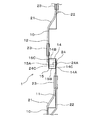
図20は、巻取軸56の構成要素となっている前述の回転体63にシャッターカーテン1の上端部を結合するために用いられる吊元部材85を示し、図20の(A)は、吊元部材85の正面図であり、図20の(B)は、吊元部材85の左側面図である。この吊元部材85は、例えば、シャッターカーテン1の構成部材となっている前述のパネル10と同じ材料を、すなわち、前述した平面状板材を、シャッターカーテン1の幅方向の長さを確保して切断することにより形成されており、上部は、シャッターカーテン1の厚さ方向に予め湾曲形成された湾曲部85Aとなっており、下部は、湾曲部85Aの下端部に接続され、下方へ鉛直に垂下した垂下部85Bとなっている。また、この垂下部85Bの下端部には、上向きに開口したフック部86が設けられ、このフック部86は、垂下部85Bの延長部となっている基部86Aと、パネル10の凹部11の窪み側と同じ側へ水平又は略水平に屈曲した屈曲部86Bと、この屈曲部86Bの先端から上向きに延出した上向き延出部86Cとを有するものになっている。
FIG. 20 shows a
したがって、フック部86の形状は、シャッターカーテン1の構成部材であるパネル10の下端部に前述の下端フック部として設けられている第2フック部15と同じ形状になっている。なお、図20(B)と、パネル10の下端部の第2フック部15が示されている図5、図8〜図10は、互いにシャッターカーテン1の幅方向である左右の逆方向から見た図となっている。
Therefore, the
また、湾曲部85Aの曲率半径Rは、巻取軸56の回転体63の構成部材となっていて、側面視が円形となっている前述のホイール部材65の曲率半径と同じ又は略同じになっている。また、この湾曲部85Aの湾曲長さは、ホイール部材65の全周長さの半分又は略半分となっている。
The curvature radius R of the
図21には、図15の電動式シャッター装置の設置現場において、シャッターカーテン1の上端部を吊元部材85を介して巻取軸56の回転体63に結合し、シャッターカーテン1を開閉自在とするための作業が示されている。この作業についての以下の説明は、図17で示したクラッチ68をオンとし、前述した駆動装置70を駆動させるための前述の操作装置の操作により、巻取軸56の回転体63を中心軸62を中心に回転させることによって所定の作業を行うものとするが、クラッチ68をオフとし、回転体63を中心軸62を中心に回転させること(回転体63に吊元部材85やパネル10が巻回された後は、吊元部材85やパネル10を介して回転体63を中心軸62を中心に回転させること)は、作業者が行うようにしてもよい。
FIG. 21 shows that the
車庫の出入口2の左右両側の壁等の建物躯体3にガイドレール4を取り付ける以前であって、出入口2の上側の壁等の建物躯体に取り付けた左右一対のブラケット57の間に、図15で示したカバー部材58を架け渡し配設する以前において、梯子等によりブラケット57の近く達した作業者は、左右一対のブラケット57の軸受け部60に巻取軸56の中心軸62を結合具61で回転不能に支持させ、次いで、作業者は、複数の吊元部材85の湾曲部85Aを、巻取軸56の回転体63を構成しているホイール部材65の外周面にビス又はリベット等の結合具により結合し、吊元部材85の垂下部85Bの下端部を、図21から分かるように、左右一対のブラケット57の前述した取付部57A,57Bに予め取付載置しておいたまぐさ部材78,79の間の図19のスリット80から下方へ垂下させ、これにより、吊元部材85の下端部に設けられているフック部86をまぐさ部材78,79の下方へ突出させる。
Before the
そして、このように湾曲部85Aが巻取軸56のホイール部材65の外周面に取り付けられる吊元部材85を、図21に示されているように、巻取軸56の中心軸62の軸方向であるシャッターカーテン1の幅方向に複数個並設する。
Then, the
なお、吊元部材85の湾曲部85Aをホイール部材65の外周面にビス又はリベット等の結合具により結合する際には、前述したように、湾曲部85Aの曲率半径Rがホイール部材65の曲率半径と同じ又は略同じになっていて、湾曲部85Aの湾曲長さは、ホイール部材65の全周長さの半分又は略半分となっているため、湾曲部85Aを少し拡開させることにより、この湾曲部85Aをホイール部材65の外周に容易に密着させて嵌合させることができ、また、この嵌合後の湾曲部85Aは、ホイール部材65の全周の長さの半分又は略半分に渡る長さを有しているため、湾曲部85Aをホイール部材65の全周の長さの半分又は略半分に渡ってビス又はリベット等の結合具により結合することができ、これにより、ホイール部材65に対する湾曲部85Aの充分に長い結合長さを確保することができて、ホイール部材65に湾曲部85Aを大きな強度で結合することができる。
When the
また、本実施形態の吊元部材85は、シャッターカーテン1の幅方向の長さを有するものとなっているため、図21に示されているように、複数のホイール部材65に跨る幅寸法を有しており、このため、吊元部材85の湾曲部85Aをホイール部材65の外周面にビス又はリベット等の結合具により結合することは、それぞれの吊元部材85の湾曲部85Aを複数のホイール部材65に跨らせて行われている。しかし、吊元部材を、シャッターカーテン1の幅方向の幅寸法が短いものとし、それぞれの吊元部材の湾曲部を1個のホイール部材の外周面に結合してもよい。
Further, since the
次いで、作業者は、吊元部材85と座板8を除くシャッターカーテン1の主要部を形成するためにシャッターカーテン1の開閉移動方向に連設される複数のパネル10のうち、最上段のパネル10の上端部の第1フック部14を、それぞれ吊元部材85の下端部のフック部86に上から嵌合し、吊元部材85のフック部86と最上段のパネル10の第1フック部14とを、パネル10同士を連結する場合と同様に、リベットにより連結する。この後に、作業者は、前述した操作装置を操作することで前述の駆動装置70を駆動させ、これにより、巻取軸56の回転体63を中心軸62に対して逆回転させることによって吊元部材85の垂下部85Bを回転体63で巻き取るとともに、最上段のパネル10のうち、下端部の第2フック部15及びこの第2フック部15よりも少し上側部分を、まぐさ部材78,79の下方へ突出していて、回転体63に巻き取られていない巻き残し箇所にして、最上段のパネル10の大部分を回転体63で巻き取る。
Next, the operator selects the uppermost panel among the plurality of
なお、吊元部材85に最上段のパネル10を連結するために、吊元部材85のフック部86と、最上段のパネル10の上端部に前述の上端フック部となって設けられている第1フック部14とを互いに嵌合させる作業は、最上段のパネル10の第1フック部14を吊元部材85のフック部86に上から嵌合することにより行えるため、この作業を容易に行える。
In order to connect the
この後に、作業者は、図11の実施形態と同様に、上から2段目のパネル10を持ち上げて、このパネル10の上端部の第1フック部14を、最上段のパネル10の下端部に前述の下端フック部となって設けられている第2フック部15に上から嵌合し、そして、これらのパネル10同士を、前述したようにリベット24により連結する。この後に、作業者は、前述した操作装置を操作することにより、巻取軸6の回転体63を中心軸62に対して再度逆回転させ、これにより、上から2段目のパネル10のうち、下端部の第2フック部15及びこの第2フック部15よりも少し上側部分を、まぐさ部材78,79の下方へ突出していて、回転体63に巻き取られていない巻き残し箇所にして、上から2段目のパネル10の大部分を回転体63で巻き取る。
After that, the operator lifts the
これ以後の作業は、前述した実施形態の作業と同じであり、下から2段目のパネル10に最下段のパネル10を連結した後に、このパネル10の下端部の第2フック部15に座板8を取り付ける作業を行うことにより、吊元部材85と複数のパネル10と座板8とからなるシャッターカーテン1を形成する。
Subsequent operations are the same as those of the above-described embodiment. After the
なお、前述したように、吊元部材85のフック部86の形状は、それぞれのパネル10の下端部に前述の下端フック部として設けられている第2フック部15と同じ形状になっているため、吊元部材85に最上段のパネル10を連結するための作業を、それぞれのパネル10を、これらのパネル10に上端フック部、下端フック部として設けられている第1フック部14、第2フック部15により連結するための作業と同じ作業内容にして行えることになり、作業の容易化を図ることができる。
As described above, the
また、最下段のパネル10の下端部の第2フック部15に座板8を取り付ける作業は、この第2フック部15に、図10で示す座板8のフック部35を上から嵌合することにより行われ、座板8のフック部35は、それぞれのパネル10に上端フック部として設けられている第1フック部14と同じ形状になっているため、最下段のパネル10に座板8を連結するための作業も、吊元部材85に最上段のパネル10を連結するための作業や、それぞれのパネル10同士を連結するための作業と同じ作業内容にして行えることになり、座板8の取付作業の容易化も図ることができる。
Further, the work of attaching the
上述したように最下段のパネル10の下端部の第2フック部15に座板8を取り付けた後に、作業者は、さらに前述した操作装置を操作することにより、巻取軸6の回転体63を中心軸62に対して逆回転させ、これにより、座板8がまぐさ部材78,79と同じ高さ位置又はこれよりも少し低い位置に達した後に、出入口2の左右両側の壁等の建物躯体3に図15で示した左右一対のガイドレール4を取り付ける作業を行う。この取付作業は、図19の二点鎖線で示されているように、ガイドレール4の上端部を、2個の取付部57A,57Bの間に挿入して行い、このときに、最下段のパネル10の下部におけるシャッターカーテン1の幅方向の両端部を、左右一対のガイドレール4の内部に挿入する。次いで、作業者が、前述した操作装置の操作により巻取軸6の回転体63を中心軸62に対して正回転させ、これにより、回転体63からシャッターカーテン1を繰り出し、これにより、最下段のパネル10から、それぞれのパネル10の幅方向両端部を左右のガイドレール4の内部に挿入する作業を行い、これにより、シャッターカーテン1は、左右一対のガイドレール4と、これらのガイドレール4の実質的に上方へ延長された部分としてブラケット57に設けられている延長部81とに案内されて上下方向に開閉移動自在となる。
As described above, after attaching the
この後に、出入口2の上側の壁等の建物躯体に取り付けている左右一対のブラケット57の間に、図15で示したカバー部材58を架け渡し配設するなどの残余の作業を行う。
After this, the remaining work such as placing the
なお、左右一対のブラケット57の取付部57A,57Bにまぐさ部材78,79を取付載置して、これらの取付部57A,57Bの間にシャッターカーテン1を上下に挿通させるためのスリット80を形成する作業は、上述の残余の作業の一部として行ってもよい。
Note that the
以上説明した実施形態によると、シャッターカーテン1の上端部は巻取軸56の回転体63に直接結合されておらず、この上端部は、平面状板材により形成された吊元部材85を介して回転体63に結合されているとともに、吊元部材85のうち、回転体63を構成しているホイール部材65の外周に結合される箇所は、巻取軸56の外形となっているホイール部材65の外形の一部と同じ形状又は略同じ形状の湾曲部85Aとして予め形成されているため、巻取軸56とシャッターカーテン1との間に吊元部材85を介設し、この吊元部材85によりシャッターカーテン1の上端部を巻取軸56に連結するという構造にしても、巻取軸56の外周面からの吊元部材85の湾曲部85Aの突出量は大きくならず、このため、吊元部材85の上にシャッターカーテン1が巻き取られても、巻取軸56におけるシャッターカーテン1の巻径は大きくならず、このため、図15で示したシャッターケース55の内部に巻取軸56を収納しても、このシャッターケース55を小型化することができる。
According to the embodiment described above, the upper end portion of the
また、シャッターカーテン1の主要部を構成するそれぞれのパネル10が、シャッターカーテン1の厚さ方向に凹凸となった凹部11と凸部12とをシャッターカーテン1の開閉移動方向に連続させたものになっていても、巻取軸56が回転してシャッターカーテン1を巻き取ることは、吊元部材85のうち、湾曲部85Aの下端部に接続されていて、下方へ鉛直に垂下している平板状の垂下部85Bを巻取軸56が巻き取ることから開始されるため、巻取軸56でのシャッターカーテン1の巻き取りを円滑に行え、また、巻取軸56での巻径を小さくして行えることになる。
In addition, each
また、上述のようにシャッターカーテン1の主要部を構成するそれぞれのパネル10が、シャッターカーテン1の厚さ方向に凹凸となった凹部11と凸部12とをシャッターカーテン1の開閉移動方向に連続させたものとなっていても、左右一対のガイドレール4の上方には、これらのガイドレール4を実質的に上方へ延長する延長部81がブラケット57に設けられ、この延長部81を形成する2個の部分81A,81Bは、上方へ延びるにしたがい互いの間隔が大きくなっているため、延長部81は上方へ末広がり形状となっているとともに、2個の部分81A,81Bのうち、ブラケット57に設けられている軸受け部60に近い一方の部分81Aは、軸受け部60の高さ位置まで達しておらず、他方の部分81Bは、軸受け部60の高さ位置と同じ位置、又は軸受け部60の高さ位置に近い位置、又は軸受け部60の高さ位置を越える位置まで達しているため、図19のA方向に回転する巻取軸56によってシャッターカーテン1が巻き取られる際、及びA方向と逆方向に回転する巻取軸56の回転体63によってシャッターカーテン1が巻取軸56から繰り出される際に、座板8の重量が軽く、このため、巻取軸56の回転体63でのシャッターカーテン1の巻き径が大きくなっていても、シャッターカーテン1の上下の開閉移動を、ガイドレール4と延長部81とにより所定どおり行わせることができ、特に、巻き径が大きくなっているシャッターカーテン1が巻取軸56の回転体63から繰り出される際に、延長部81のうち、上下寸法が大きくなっている部分81Bの案内作用により、シャッターカーテン1をこの延長部81からガイドレール4へと円滑に導くことができる。
Further, as described above, each
なお、延長部81は、ガイドレール4の上部に、ガイドレール4の一部としても形成してもよい。
The
しかし、本実施形態のように、ガイドレール4の上方に、これらのガイドレール4を実質的に上方へ延長するための延長部81をブラケット57に設けることにより、前述したように、シャッター装置の設置現場において、巻取軸56の回転体63の回転により、シャッターカーテン1を構成する吊元部材85やそれぞれのパネル10を巻き取った後に、左右一対のガイドレール4を出入口2の左右両側の壁等の建物躯体3に取り付ける作業を容易に行えるようになる。
However, as described above, by providing the
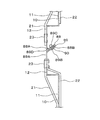
また、図19で示したシャッターカーテン1の最大巻き直径Dを、全開位置に達したときにおけるシャッターカーテン1の自然状態での巻き直径とした場合には、延長部81を形成している2個の部分81A,81Bのうち、上下寸法が長い部分81Bの上部を最大巻き直径Dの内部に侵入させた構成としてもよい。これによると、全開位置に達したシャッターカーテン1が、このシャッターカーテン1が巻き取られている巻取軸56において、自然状態の最大巻き直径Dまで大きく膨らむことを阻止することができる。
Further, when the maximum winding diameter D of the
なお、巻取軸56の外周に取り付けられる吊元部材85を、図21で示したように、シャッターカーテン1の幅方向である左右方向に複数設ける場合には、左右両端に配置される吊元部材85の一部又は全部を左右のガイドレール4の上部の位置と一致させてもよいが、これらの吊元部材85を左右のガイドレール4の配置位置からずらせてこれらのガイドレール4の間に配置することが好ましい。このように左右両端に配置される吊元部材85を左右のガイドレール4の間に配置すると、吊元部材85と、シャッターカーテン1の構成部材となっている前述の最上段のパネル10との連結箇所の全体の位置が、ガイドレール4の外部に露出した位置となるため、吊元部材85と最上段のパネル10との連結を解除する作業を行うことが必要になったときに、この作業を容易に行えることになる。吊元部材の個数を、左右方向の幅寸法が大きい1個とした場合にも、上記と同じ理由により、この吊元部材を左右のガイドレール4の間に配置することが好ましい。
In addition, as shown in FIG. 21, when providing the hanging
図22は、シャッターカーテン1の主要部となる上下2個のパネル10同士をシャッターカーテン1の開閉移動方向に連結するための別実施形態の構造を示す。この実施形態では、上側のパネル10の下端部の凸部12の下先端部に、この凸部12の下向きの延長部となっている基部88Aと、この基部88Aから上向きに傾斜して車庫の外部側から内部側に延びている上向き傾斜部88Bとからなる被係止部88が設けられている。また、下側のパネル10の上端部の凸部12の上先端部には、この凸部12の上向きの延長部となっている基部89Aと、この基部89Aから、被係止部88の上向き傾斜部88Bと同じ又は略同じ角度により、上向きに傾斜して車庫の外部側から内部側に延びている上向き傾斜部89Bと、この上向き傾斜部89Bの先端から、車庫の外部側へ上向き傾斜部89Bと同じ又は略同じ角度により下向きに延びている下向き傾斜部89CとからなるU字状又は略U字状の係止部89が設けられている。
FIG. 22 shows the structure of another embodiment for connecting two upper and
係止部89の上向き傾斜部89Bと下向き傾斜部89Cとの間に被係止部88の上向き傾斜部88Bを挿入した後に、係止部89の上向き傾斜部89Bと下向き傾斜部89C及び被係止部88の上向き傾斜部88Bに形成されている孔に、上下2個のパネル10同士を連結するための連結手段であって、ブラインドリベットになっているリベット90のうち、頭部90Aから延出している軸部90Bを車庫の内部側から外部側へ貫通させ、軸部24Bのうち、これらの孔からシャッターカーテン1の厚さ方向に突出した先端部に、圧縮荷重により突出部90Cを圧縮膨出させて形成する。これにより、上下2個のパネル10同士は、リベット90により連結される。
After inserting the upward
パネル10の上下両端部に設けられるこれらの被係止部88と係止部89も、前述した第1フック部14及び第2フック部15と同様に、上下2個のパネル10を連結するために互いに嵌合されるフック部となっているとともに、被係止部88は、パネル10の下端部に設けられた下端フック部となっており、係止部89は、パネル10の上端部に設けられた上端フック部となっている。
These locked
この実施形態によると、リベット90の軸部90Bは、上下2個のパネル10の連結箇所となっている係止部89の上向き傾斜部89Bと下向き傾斜部89C及び被係止部88の上向き傾斜部88Bを貫通していて、シャッターカーテン1の厚さ方向の成分を有している貫通部になっており、また、この貫通部の先端部は、上記連結箇所から突出し、シャッターカーテン1の厚さ方向の成分を有している突出部90Cとなっている。
According to this embodiment, the
そして、この実施形態では、上側のパネル10における下端部の凸部12や、被係止部88の基部88Aは、突出部90Cを、この突出部90Cをシャッターカーテン1の厚さ方向に越えた位置で覆うための覆い部となっており、このため、突出部90Cが、シャッターカーテン1の開閉移動時等において、シャッターカーテン1の外部のものに接触することを、この覆い部により防止することができる。
In this embodiment, the
図23は、上下2個のパネル10同士をシャッターカーテン1の開閉移動方向に連結するためのさらに別実施形態に係る構造を示す。この実施形態では、上側のパネル10の下端部の凸部12の下先端部に、この凸部12の下向きの延長部となっている基部91Aと、この基部91Aから、車庫の内部側において、鉛直上向きに延びている上向き鉛直部91BとからなるU字状又は略U字状の第1係合部91が設けられている。また、下側のパネル10の上端部の凸部12の上先端部には、この凸部12の上向きの延長部となっている基部92Aと、この基部92Aから、車庫の外部側において、鉛直下向きに延びている下向き鉛直部92BとからなるU字状又は略U字状の第2係合部92が設けられている。
FIG. 23 shows a structure according to yet another embodiment for connecting two upper and
第1係合部91と第2係合部92とを係合させた後に、第1係合部91の基部91Aと上向き鉛直部91B及び第2係合部92の基部92Aと下向き鉛直部92Bに形成されている孔に、上下2個のパネル10同士を連結するための連結手段であって、ブラインドリベットになっているリベット93のうち、頭部93Aから延出している軸部93Bを車庫の外部側から内部側へ貫通させ、軸部93Bのうち、これらの孔からシャッターカーテン1の厚さ方向に突出した先端部に、圧縮荷重により突出部93Cを圧縮膨出させて形成する。
After engaging the
パネル10の上下両端部に設けられる第1係合部91と第2係合部92も、前述した第1フック部14及び第2フック部15等と同様に、上下2個のパネル10を連結するために互いに嵌合されるフック部となっているとともに、第1係合部91は、パネル10の下端部に設けられた下端フック部となっており、第2係合部92は、パネル10の上端部に設けられた上端フック部となっている。
The first engaging
この実施形態によると、リベット93の軸部93Bは、上下2個のパネル10の連結箇所となっている第1係合部91の基部91Aと上向き鉛直部91B及び第2係合部92の基部92Aと下向き鉛直部92Bをシャッターカーテン1の厚さ方向の成分を有して貫通していて、パネル10の凸部12から凹部11側へ貫通した貫通部になっており、また、この貫通部の先端部は、上記連結箇所から突出した突出部93Cとなっている。
According to this embodiment, the
そして、この実施形態では、突出部93Cの突出量は、パネル10における凸部12の凹部11からの張り出し量Lよりも小さくなっている。すなわち、凸部12のシャッターカーテン厚さ方向反対側は、車庫の内部側から外部側へ窪んだ窪み部94となっており、車庫の外部側である凸部12から車庫の内部側に挿入されたリベット93の軸部93Bの先端部は、窪み部94に突出部93Cとして突出しており、この突出量は、窪み部94の窪み量となっている凸部12の凹部11からの張り出し量Lよりも小さくなっている。
In this embodiment, the protruding amount of the protruding
このため、この実施形態でも、突出部93Cが、シャッターカーテン1の開閉移動時等において、シャッターカーテン1の外部のものに接触することを、窪み部94により防止することができ、また、巻取軸6,56によるシャッターカーテン1の巻き取り、繰り出しを所定通り行える。
For this reason, also in this embodiment, it is possible to prevent the projecting
なお、図22及び図23の実施形態において、上下2個のパネル10同士が連結されると、上側のパネル10の下端部の凸部12と下側のパネル10の下端部の凸部12は、これらのパネル10を含んで構成されるシャッターカーテン1全体の凸部を形成することになり、この凸部の上下に、上側のパネル10の凹部11と下側のパネル10の凹部11とによる凹部がシャッターカーテン1の開閉移動方向に連続して設けられることになる。
22 and FIG. 23, when the two upper and
以上説明したそれぞれの実施形態において、パネル10の第2フック部15及び吊元部材85のフック部86についてのシャッターカーテン1の厚さ方向の向きは、どちらの向きでもよい。しかし、シャッターカーテン1が巻取軸6,56により繰り出し自在に巻き取られるものである場合には、巻取軸6,56に円滑に巻き取り可能となるようにするために、パネル10の第2フック部15及び吊元部材85のフック部86についてのシャッターカーテン1の厚さ方向の向きを、巻取軸6,56の表面側とは反対側の向きとすることが好ましい。また、パネル10にほかのパネル10を連結したり、吊元部材85にパネル10を連結したりする作業を容易に行えるようにするために、パネル10の第2フック部15及び吊元部材85のフック部86についてのシャッターカーテン1の厚さ方向の向きを、大きな空間の側に向いた向きすることが好ましく、例えば、図1のシャッターケース5や図15のシャッターケース55が用いられる場合には、これらのシャッターケース5,55が取り付けられる前述の建物躯体の側とは反対側に向いた向きとすることが好まし。
In each embodiment described above, the direction of the
さらに、シャッター装置が、前述したように、車庫等の建物に設けられた出入口等の開口部に設置され、これにより、シャッターカーテン1が建物の内外を仕切るものとなっている場合には、パネル10の第2フック部15及び吊元部材85のフック部86についてのシャッターカーテン1の厚さ方向の向きを、建物の内側に向いた向きすることが好ましい。これによると、これらの第2フック部15及びフック部86にほかのパネル10等を連結するために用いる図8及び図9のリベット24等の止着具が、建物の内側に頭部が露出したものとなるため、防犯上及び意匠上有効となる。
Further, as described above, the shutter device is installed in an opening such as an entrance / exit provided in a building such as a garage, so that the
また、図19で示したガイドレール4のための延長部81は、少なくとも主要部が複数のパネル10の連結によって構成されていないほかのシャッターカーテンにも適用することができ、その一例のシャッターカーテンは、複数のスラットがシャッターカーテン開閉移動方向に連設されることによって少なくとも主要部が構成されているスラット式シャッターカーテンである。また、延長部81と同様の構成を、ガイドレール4の上方だけではなく、例えば、シャッターカーテンの幅方向における中央部又は略中央部又はほかの箇所の上方に設けてもよい。これによると、シャッターカーテン1のうちの少なくとも主要部が、凹部11と凸部12が設けられた複数のパネル10を連結することによって構成されていて、これらの凹部11と凸部12のためのシャッターカーテン1が巻取軸6,56に対して巻き取りにくく、繰り出しにくいものになっていても、これらの巻き取りと繰り出しを容易に行えるようになる。
Further, the
また、パネル10等のシャッターカーテン1を構成する部材には、シャッターカーテンの幅方向の端部がガイドレール4から抜けることを防止するための抜け止め部材(言い換えると、耐風フック部材)を設けてもよい。このような抜け止め部材は、抜け止め部材の取付作業を容易に行えるようにするために、パネル10同士の連結部やパネル10と吊元部材85との連結部を避けた箇所に設けることが好ましい。しかし、このような連結部の箇所に抜け止め部材を設けてもよく、このように連結部の箇所に抜け止め部材を設ける場合には、パネル10同士等を連結するためのリベット等の止着具により抜け止め部材をパネル10等に取り付けることが好ましい。
Further, a member constituting the
また、シャッターカーテン1に、このシャッターカーテン1を上下に手動で開閉移動できるようにするための手掛け部材や、開閉移動不能とするための施錠装置を設ける場合には、シャッターカーテン1やパネル10の製造上の観点から、これらの手掛け部材や施錠装置を、パネル10同士の連結部やパネル10と吊元部材85との連結部を避けた箇所に設けることが好ましい。
When the
図24は、上下2個のパネル10同士についてのさらに別実施形態に係る連結構造を示す。この実施形態でも、図8及び図9の実施形態と同様に、それぞれのパネル10の上端部に第1フック部14が設けられ、それぞれのパネル10の下端部に第2フック部15が設けられている。そして、第1フック部14は、基部14Aと、この基部14Aの先端からシャッターカーテン1の厚さ方向のうち、凸部12の張り出し側と同じ側へ水平又は略水平に屈曲した屈曲部14Bと、この屈曲部14Bの先端から下向きに延出した下向き延出部14Cとにより形成されている。第2フック部15は、基部15Aと、この基部15Aの先端からシャッターカーテン1の厚さ方向のうち、凹部11の窪み側と同じ側へ水平又は略水平に屈曲した屈曲部15Bと、この屈曲部15Bの先端から上向きに延出した上向き延出部15Cとにより形成されている。
FIG. 24 shows a connection structure according to yet another embodiment of the two upper and
そして、この実施形態では、上下2個のパネル10のうち、下側のパネル10の上端部に設けられている第1フック部14の下向き延出部14Cを、上側のパネル10の下端部に設けられている第2フック部15の屈曲部15Bに当接させるとともに、上側のパネル10の下端部に設けられている第2フック部15の上向き延出部15Cを、下側のパネル10の上端部に設けられている第1フック部14の屈曲部14Bに当接させている。
And in this embodiment, the
このため、この実施形態によると、第1フック部14の下向き延出部14Cは、下側のパネル10の上端部における下方向への成分を有して折り曲げられた下方向折り曲げ部となっているとともに、第2フック部15の上向き延出部15Cは、上側のパネル10の下端部における上方向への成分を有して折り曲げられた上方向折り曲げ部となっており、下方向折り曲げ部は、上側のパネル10の構成部分となっている屈曲部15Bに、上方向折り曲げ部は、下側のパネル10の構成部分となっている屈曲部14Bに、それぞれ当接していることになる。したがって、上下2個のパネル10を、前述した連結箇所を貫通する部分を有する連結手段となっているリベット24により連結する作業を行う際に、この作業を、下側のパネル10の重量を上側のパネル10によって支持させながら行うことができ、このため、この作業を、一人の作業者が、下側のパネル10から離した両手により容易に行えるようになる。
Therefore, according to this embodiment, the downward extending
なお、上述した下方向折り曲げ部と上方向折り曲げ部とのうち、一方だけを、この一方が設けられていないパネル10の構成部分に当接させてもよく、これによっても上下2個のパネル10をリベット24により連結する作業を行う際に、この作業を、下側のパネル10の重量を上側のパネル10によって支持させて行うことができるため、この作業を容易に行える。すなわち、例えば、下側のパネル10の下方向折り曲げ部となっている下向き延出部14Cを、上側のパネル10の構成部分となっている屈曲部15Bに当接させ、上側のパネル10の上方向折り曲げ部となっている下向き延出部15Cを、下側のパネル10の構成部分となっている屈曲部14Bに当接させなくても、上下2個のパネル10をリベット24により連結する作業を行う際に、この作業を、下側のパネル10の重量を上側のパネル10によって支持させて行うことができて、この作業を容易に行える。
It should be noted that only one of the above-described downward bent portion and the upward bent portion may be brought into contact with a component of the
また、前述した図22で示した実施形態では、上下2個のパネル10のうち、上側のパネル10の被係止部88を形成している上向き傾斜部88Bの先端に、下側のパネル10に設けられているU字状又は略U字状の係止部89が当接しており、図23で示した実施形態では、上下2個のパネル10の第1係合部91と第2係合部92は、互いに他方のパネル10の構成部分に当接する上方向折り曲げ部、下方向折り曲げ部となっている上向き鉛直部91B、下向き鉛直部92Bを有しており、このため、図22及び図23の実施形態でも、上下2個のパネル10をリベット90,93により連結する作業を行う際に、この作業を、下側のパネル10の重量を上側のパネル10によって支持させながら容易に行うことができる。
In the embodiment shown in FIG. 22 described above, the
図25は、図22で示した上下2個のパネル10の連結構造を改良した実施形態を示している。この実施形態では、下側のパネル10の上端部に上端フック部として設けられている係止部89の構成部分のうち、下向き傾斜部89Cの先端部には、この下向き傾斜部89Cから角度をもって起き上がった起き上がり部89Dが形成されている。
FIG. 25 shows an embodiment in which the connecting structure of the two upper and
このため、係止部89の上向き傾斜部89Bと下向き傾斜部89Cとの間に、上側のパネル10の下端部に設けられている被係止部88の上向き傾斜部88Bを挿入する作業を行う際に、この作業を、起き上がり部89Dの案内作用により容易に行える。
For this reason, the operation of inserting the upward
図26も、図22で示した上下2個のパネル10の連結構造を改良した実施形態を示している。この実施形態では、下側のパネル10の上端部の上端フック部となっている係止部89を構成している部分のうち、下向き傾斜部89Cは上向き傾斜部89Bと平行になっておらず、下向き傾斜部89Cは、下向きに延びるにしたがい上向き傾斜部89Bから離れる方向へ延びている。
FIG. 26 also shows an embodiment in which the connecting structure of the two upper and
このため、係止部89の上向き傾斜部89Bと下向き傾斜部89Cとの間に、上側のパネル10の下端部に設けられている被係止部88の上向き傾斜部88Bを挿入する作業を容易に行えることになる。また、これらの係止部89と被係止部88を図22で示したリベット90で連結すると、このリベット90の突出部90Cからの押圧力により、下向き傾斜部89Cは上向き傾斜部89Bと平行になり、これらの上向き傾斜部89Bと下向き傾斜部89Cとで被係止部88の上向き傾斜部88Bを挟着させることができる。
For this reason, the operation | work which inserts the
なお、図25の実施形態と図26の実施形態は、上述したように図22で示した上下2個のパネル10の連結構造を改良した実施形態であるが、図22の実施形態と同様に、これらの図25の実施形態と図26の実施形態でも、上下2個のパネル10のうち、上側のパネル10の被係止部88を形成している上向き傾斜部88Bの先端に、下側のパネル10に設けられているU字状又は略U字状の係止部89が当接するため、上下2個のパネル10をリベット90により連結する作業を行う際に、この作業を、下側のパネル10の重量を上側のパネル10によって支持させながら容易に行うことができる。
The embodiment of FIG. 25 and the embodiment of FIG. 26 are embodiments in which the connection structure of the two upper and
また、図24で示した実施形態では、上下2個のパネル10のうち、下側のパネル10の上端部に設けられている第1フック部14の下向き延出部14Cは、上側のパネル10の下端部に設けられている第2フック部15の基部15Aに当接し、上側のパネル10の第2フック部15の上向き延出部15Cは、下側のパネル10の第1フック部14の基部14Aに当接しているため、下向き延出部14Cと基部15Aの箇所及び上向き延出部15Cと基部14Aの箇所は、それぞれ二重構造となっており、このため、これらのパネル10を含んで構成されたシャッターカーテン1が巻取軸6に巻き取られたときに、シャッターカーテン1の巻径方向等についての充分に大きい強度を確保でき、これにより、リベット24に過大な荷重が作用することを防止して、このリベット24にぐらつきなどが生ずることをなくすことができる。
In the embodiment shown in FIG. 24, the downwardly extending
図27は、パネル10に設ける接触防止部材となっているベルト部材についての別実施形態を示している。この実施形態では、パネル10についてのシャッターカーテン1の厚さ方向の両側の面のうち、前述した車庫の外部側の面には、前述したそれぞれの実施形態と同様に、パネル10の凹部11と凸部12に渡る長さ寸法を有している第1ベルト部材21が取り付けられ、この第1ベルト部材21は、パネル10の凹部11と凸部12の形状に倣ってシャッターカーテン1の厚さ方向に蛇行しながら上下方向へ延びている。しかし、パネル10の車庫の内部側の面に、パネル10の凹部11と凸部12に渡る長さ寸法を有して取り付けられている第2ベルト部材122は、凹部11と凸部12の形状に倣ってシャッターカーテン1の厚さ方向に蛇行しておらず、パネル10に設けられている複数の凹部11(第2ベルト部材122側からすると凸部)を直接繋ぐように直線的に上下方向へ延びている。
FIG. 27 shows another embodiment of the belt member serving as a contact preventing member provided on the
これを言い換えると、シャッターカーテン1を構成するパネル10において、凹部11の個数は、少なくとも1個であって、凸部12の個数は、この凹部11のシャッターカーテン1の開閉移動方向の両側に設けられている少なくとも2個であり、図27の実施形態でも、第1及び第2ベルト部材21,122は、シャッターカーテン1の開閉移動方向に間隔をあけて2個設けられている凸部12と、これらの凸部12の間に設けられている凹部11とに渡る長さ寸法を有しており、第1ベルト部材21は、凹部11において、この凹部11の形状にしたがってシャッターカーテン1の厚さ方向に折り曲げられているが、第2ベルト部材122は、第2ベルト部材122側からすると凹部となっている凸部12において、この凸部12の形状にしたがって折り曲げられたものになっておらず、この凸部12のシャッターカーテン1の開閉移動方向の両側に、第2ベルト部材122側からすると凸部となって2個設けられている凹部11の間に、第2ベルト部材122が直線状態又は略直線状態で架け渡されている。
In other words, in the
この実施形態によると、第1ベルト部材21と第2ベルト部材122をパネル10に取り付けるために、図7等で示したステープル23を用いる場合には、このステープル23による第1ベルト部材21と第2ベルト部材122の取り付けを、凹部11のみにおいて行えばよく、このため、パネル10への第1ベルト部材21と第2ベルト部材122の取付作業を容易に行えるようになる。
According to this embodiment, when the staple 23 shown in FIG. 7 or the like is used to attach the
なお、第1ベルト部材21と第2ベルト部材122をパネル10に取り付けるために前述した接着剤を用いる場合には、第1ベルト部材21を、凹部11と凸部12のうち、凹部11だけに、又は凸部12だけに、又は凹部11と凸部12の両方に接着してもよく、また、第2ベルト部材122は、凹部11だけに接着する。
In addition, when using the adhesive agent mentioned above in order to attach the
また、これまで説明したそれぞれの実施形態において、第1ベルト部材22と第2ベルト部材22,122を緊張状態にさせてパネル10に取り付けることは好ましくなく、これらのベルト部材21,22、122を多少弛緩してパネル10に取り付けることが好ましい。これによると、シャッターカーテン1を巻取軸5,56で円滑に巻き取り、繰り出すことができるようになり、また、ステープル23の破損や接着剤の剥離等を防止して、第1ベルト部材22と第2ベルト部材22,122がパネル10から分離しないようにすることができる。
Further, in each of the embodiments described so far, it is not preferable to place the
また、図27の実施形態では、図14の実施形態と同様に、凹部11の下端と凸部12の上端とを繋いでいる繋ぎ部13’は、下方への傾斜角度をもって前述の車庫の内部側から外部側へ延びており、凸部12の下端と凹部11の上端とを繋いでいる繋ぎ部13’’は、下方への傾斜角度をもって車庫の外部側から内部側へ延びている。そして、凹部11と繋ぎ部13’,13’’との接続箇所及び凸部12と繋ぎ部13’,13’’との接続箇所は、湾曲した形状の接続箇所となっている。
In the embodiment of FIG. 27, as in the embodiment of FIG. 14, the connecting
図28は、店舗の出入口2を開閉するためのシャッターカーテン1を有する店舗用の手動式シャッター装置を示しており、このシャッターカーテン1には、シャッターカーテン1に設けられる付属部材となっている施錠装置100、手掛け部材101及び配達物投入部材102が取り付けられている。配達物投入部材102は、新聞や郵便物等の配達される物を、全閉となったシャッターカーテン1で出入口2が仕切られている店舗の外部から店舗の内部へ投入できるようにするためのものである。そして、この実施形態のシャッターカーテン1の主要部は、これまで説明したそれぞれの実施形態と同様に、凹部11と凸部12がシャッターカーテン1の開閉移動方向にそれぞれ複数個形成されている複数個のパネル10をシャッターカーテン1の開閉移動方向に連結することにより構成されている。
FIG. 28 shows a manual shutter device for a store having a
図29は、図28のS29−S29線断面図であり、この図29に示されているように、施錠装置100、手掛け部材101及び配達物投入部材102は、シャッターカーテン1の主要部を形成している複数個のパネル10のうち、1個のパネル10に設けられている。特に、施錠装置100と手掛け部材101は、このパネル10における人の腰の高さ位置に配置されている。施錠装置100は、キーが差し込まれるキー差し込み部100Aと、サムターン部材100Bが配置された本体部100Cとを有し、キー差し込み部100Aに差し込んだキーの回動操作及びサムターン部材100Bの回動操作により、本体部100Cからシャッターカーテン1の幅方向に延びている図28の一対のスライド部材100Dがシャッターカーテン1の幅方向にスライド移動し、ばね等で構成されている中継装置100Eを介してスライド部材100Dに連結されているラッチ部材100Fが、ガイドレール4の内部に取り付けられているラッチ受け部材100Gに係合することにより、全閉位置に達しているときのシャッターカーテン1が、施錠装置100により施錠される。
29 is a sectional view taken along line S29-S29 in FIG. 28. As shown in FIG. 29, the
図28に示されているように、施錠装置100の両側に2個設けられる手掛け部材101は、図29に示されているように、フランジ部101Aと、このフランジ101A側が開口したボックス部101Bとからなり、このボックス101Bの内部にフランジ部101側から挿入した手により、シャッターカーテンを上下方向に開閉移動させることができる。また、配達物投入部材102は、厚板状のベース部材102Aと、このベース部材102Aに窓状に形成されている配達物投入口102Bを開閉するために、ベース部材102Aに結合されている軸102Cを中心に揺動自在であって、ねじりコイルばね102Dにより常時配達物投入口102Bを閉じる方向へ付勢されている蓋部材102Eとからなり、新聞等の配達物を配達物投入口102Bに投入したきに開き揺動したこの蓋部材102Eは、配達物が通過した後に、ねじりコイルばね102Dにより常時配達物投入口102Bを閉じる。
As shown in FIG. 28, two handle
施錠装置100と手掛け部材101は、パネル10に複数個設けられている凸部12ののうち、同じ凸部12に配置されている。すなわち、この凸部12の裏側の面、すなわち、店舗の内側の面には、厚板状の補強部材103が配置され、この補強部材103と凸部12に形成されている孔に、施錠装置100のキー差し込み部100Aが店舗の内側から外側へ挿入され、凸部12から店舗の外側へ突出したキー差し込み部100Aの外周に化粧部材104が配置され、この化粧部材104が、補強部材103及び施錠装置100の本体部100Cまで達するビス等の止着具105により、凸部12に取り付けられている。また、補強部材103と凸部12には、手掛け部材101のボックス部101Bを挿入するために孔が設けられ、これらの孔にボックス部101Bが、店舗の外側から内側へ挿入された後に、凸部12の店舗の外側の面に露出しているフランジ部101Aが、補強部材103まで達するビス等の止着具106により、凸部12に取り付けられている。
The
図29に示されているように、配達物投入部材102は、以上のようにして施錠装置100と手掛け部材101が配置される凸部12の上側にこの凸部12と連続して形成されている凹部11において、パネル10に配置されている。この凹部11には、配達物投入部材102の配達物投入口102Bと対応する窓孔11Aが形成されており、これらの配達物投入口102Bと窓孔11Aを一致させながら、配達物投入部材102のベース部材102Aが凹部11の店舗の外側の面に配置され、蓋部材102Eは凹部11の店舗の内側の面に配置され、ベース部材102Aが、店舗の内側からパネル10に挿入したビス等の止着具107により、凹部11に取り付けられる。
As shown in FIG. 29, the
なお、施錠装置100と手掛け部材101をパネル10の同じ凸部12に配置せず、このパネル10のそれぞれ別の凸部12に分離して配置してもよい。また、図28に示されているように、配達物投入部材102を施錠装置100から長い距離離れた箇所、例えば、シャッターカーテン1の幅方向に離れた箇所に配置し、これにより、配達物投入口102Bから手を差し入れても、施錠装置100のサムターン部材100Bを回動操作できないようにすることが好ましい。
Note that the
以上説明したように、シャッターカーテン1に設けられる付属部材となっている施錠装置100、手掛け部材101及び配達物投入部材102は、シャッターカーテン1の主要部を形成している複数個のパネル10のうち、1個のパネル10に取り付けられ、これらの施錠装置100、手掛け部材101及び配達物投入部材102は、同じパネル10に配置されているため、シャッターカーテン1に施錠装置100、手掛け部材101及び配達物投入部材102を配置するためには、1個のパネル10だけに、これらの施錠装置100、手掛け部材101及び配達物投入部材102を配置するための必要となる前記補強部材103の配置や、前記孔の加工作業等を行なえばよく、このため、シャッターカーテン1全体として、このシャッターカーテンの製造作業の容易化を図ることができる。
As described above, the
また、店舗の内側へ大きく突出する部分となっているサムターン部材100B付き本体部100Cを有している施錠装置100と、同じく店舗の内側へ大きく突出する部分となっているボックス部101Bを有する手掛け部材101は、パネル10に設けられている凹部11と凸部12のうち、凸部12に配置されており、しかも、サムターン部材100B付き本体部100Cとボックス部101Bについての店舗の内側への突出量は、図29に示されているように、凹部11からの凸部12の張り出し量Lと同じ又はこれよりも小さいため、サムターン部材100B付き本体部100Cとボックス部101Bが、シャッターカーテン1の開閉移動時等において、シャッターカーテン1の外部のものに接触することを防止することができ、又は巻取軸6によるシャッターカーテン1の巻き取り、繰り出しも所定どおり行える。
Moreover, the handle which has the
また、本実施形態では、施錠装置100と手掛け部材101が配置される凸部12には、薄板で形成されているパネル10よりも厚さ寸法が大きい補強部材103が配置され、施錠装置100と手掛け部材101の共通部材となっているこの補強部材103を介して凹部11に施錠装置100と手掛け部材101が取り付けられているため、パネル10への施錠装置100と手掛け部材101の取付強度を大きくすることができる。
In the present embodiment, a reinforcing
なお、このような補強部材103と同様の補強部材を用いて配達物投入部材102をパネル10に取り付けてもよい。
Note that the
さらに、この配達物投入部材102は、パネル10に設けられている凹部11と凸部12のうち、凹部11に配置されているため、配達物投入口102Bに投入された配達物が、達物投入口102Bを通過せずに引っ掛かった状態になっても、この凹部11の上側に設けられている凸部12が庇となって、配達物が雨水に濡れるなどの事態を防止できる。
Further, since the
図30は、別実施形態に係るパネル10’を示す。このパネル10’に設けられている凹部11の個数及び凸部12の個数は、それぞれ1個である。これらの凹部11と凸部12についてのシャッターカーテン1の開閉移動方向の幅寸法は、これまで説明した実施形態のパネル10の凹部11と凸部12についてのシャッターカーテン1の開閉移動方向の幅寸法と同じ又は略同じである。このため、パネル10’についてのシャッターカーテン1の開閉移動方向の長さ寸法H’は、図5で示したパネル10についてのシャッターカーテン1の開閉移動方向の長さ寸法Hよりも小さい。
FIG. 30 shows a
そして、パネル10’の凸部12に施錠装置100と手掛け部材101が配置され、凹部11に配達物投入部材102が配置されている。また、パネル10’のシャッターカーテン1の厚さ方向両側の面には、第1ベルト部材121と第2ベルト部材222が接着剤により取り付けられ、これらのベルト部材121,222のシャッターカーテン1の開閉移動方向の長さ寸法は、前述した実施形態の第1ベルト部材21、第2ベルト部材22,122の開閉移動方向の長さ寸法よりも短くなっている。
And the
また、パネル10’の上端部には、図5等で示した実施形態のパネル10と同様に、第1フック部14が設けられ、パネル10’の下端部には、第2フック部15が設けられている。このため、この実施形態のパネル10’の上下には、上下両端部に第1フック部14と第2フック部15が設けられているパネル10を連結することができる。
In addition, a
以上説明したそれぞれの実施形態では、それぞれのパネル10,10’ごとにベルト部材21,22,122,121,222が設けられているため、シャッターカーテン1全体としては、パネル同士の連結箇所は、ベルト部材が存在しないベルト部材不存在箇所となっており、1個のパネルにおいても、ベルト部材が部分的に存在しないベルト部材不存在箇所を設けてもよい。
In each embodiment described above, since
また、図29と図30の実施形態のように、パネル10,10’に施錠装置100等の付属部材を取り付ける場合において、付属部材の取付位置がベルト部材の配置位置と干渉する場合には、その位置でのベルト部材の配置を省略してもよい。
Further, as in the embodiment of FIG. 29 and FIG. 30, when attaching an attachment member such as the
さらに、ベルト部材21,22,122,121,222の補修を行うことが必要になったときには、ベルト部材全部を取り換えてもよく、あるいは、ベルト部材全部の取り換えを行わず、ベルト部材の一部を切断して、その部分だけを新たなベルト部材に交換してもよく、あるいは、元のベルト部材を残して、その近くに新たなベルト部材を配置してもよい。
Further, when it becomes necessary to repair the
本発明は、例えば、店舗や倉庫等の出入口を開閉するための出入口用シャッター装置や、車庫用シャッター装置などの手動式、電動式の各種のシャッター装置に利用することができる。 The present invention can be used for various types of manual and electric shutter devices such as an entrance / exit shutter device for opening and closing an entrance / exit of a store or a warehouse, and a garage shutter device.
1 シャッターカーテン
4 ガイドレール
6,56 巻取軸
8 座板
10,10’ パネル
11 凹部
12 凸部
14 上端フック部である第1フック部
15 下端フック部である第2フック部
62 中心軸
63 回転体
65 ホイール部材
85 吊元部材
85A 湾曲部
85B 垂下部
86 フック部
88 下端フック部である被係止部
89 上端フック部である係止部
91 下端フック部である第1係合部
92 上端フック部である第2係合部
R 曲率半径
DESCRIPTION OF
Claims (9)
前記吊元部材は、平面状板材により形成されているとともに、前記シャッターカーテンの厚さ方向に湾曲形成された湾曲部を有しており、この湾曲部が前記巻取軸の外周に結合されていることを特徴とするシャッター装置。 A shutter curtain that opens and closes up and down, a winding shaft for winding and unwinding the shutter curtain to open and close the shutter curtain up and down, and interposed between the winding shaft and the shutter curtain In the shutter device configured to include a suspension member for connecting the shutter curtain to the winding shaft,
The suspension member is formed of a planar plate material, and has a curved portion that is curved in the thickness direction of the shutter curtain, and the curved portion is coupled to the outer periphery of the winding shaft. A shutter device.
Applications Claiming Priority (2)
| Application Number | Priority Date | Filing Date | Title |
|---|---|---|---|
| JP2015102655 | 2015-05-20 | ||
| JP2015102655 | 2015-05-20 |
Publications (2)
| Publication Number | Publication Date |
|---|---|
| JP2016217111A true JP2016217111A (en) | 2016-12-22 |
| JP6585960B2 JP6585960B2 (en) | 2019-10-02 |
Family
ID=57578128
Family Applications (6)
| Application Number | Title | Priority Date | Filing Date |
|---|---|---|---|
| JP2015146781A Active JP6572042B2 (en) | 2015-05-20 | 2015-07-24 | Shutter device |
| JP2015157284A Active JP6585958B2 (en) | 2015-05-20 | 2015-08-07 | Shutter device |
| JP2015158846A Active JP6585960B2 (en) | 2015-05-20 | 2015-08-11 | Shutter device |
| JP2015165437A Active JP6600507B2 (en) | 2015-05-20 | 2015-08-25 | Shutter device construction method |
| JP2015203415A Active JP6659301B2 (en) | 2015-05-20 | 2015-10-15 | Shutter device |
| JP2016058186A Active JP6707376B2 (en) | 2015-05-20 | 2016-03-23 | Shutter device |
Family Applications Before (2)
| Application Number | Title | Priority Date | Filing Date |
|---|---|---|---|
| JP2015146781A Active JP6572042B2 (en) | 2015-05-20 | 2015-07-24 | Shutter device |
| JP2015157284A Active JP6585958B2 (en) | 2015-05-20 | 2015-08-07 | Shutter device |
Family Applications After (3)
| Application Number | Title | Priority Date | Filing Date |
|---|---|---|---|
| JP2015165437A Active JP6600507B2 (en) | 2015-05-20 | 2015-08-25 | Shutter device construction method |
| JP2015203415A Active JP6659301B2 (en) | 2015-05-20 | 2015-10-15 | Shutter device |
| JP2016058186A Active JP6707376B2 (en) | 2015-05-20 | 2016-03-23 | Shutter device |
Country Status (1)
| Country | Link |
|---|---|
| JP (6) | JP6572042B2 (en) |
Families Citing this family (3)
| Publication number | Priority date | Publication date | Assignee | Title |
|---|---|---|---|---|
| JP6882956B2 (en) * | 2017-08-23 | 2021-06-02 | 文化シヤッター株式会社 | Shutter device |
| JP6985063B2 (en) * | 2017-08-23 | 2021-12-22 | 文化シヤッター株式会社 | Shutter device |
| US12024946B2 (en) | 2020-04-06 | 2024-07-02 | Levolor, Inc. | Shade adapter for a roller shade |
Citations (2)
| Publication number | Priority date | Publication date | Assignee | Title |
|---|---|---|---|---|
| JPH10131646A (en) * | 1996-10-30 | 1998-05-19 | Bunka Shutter Co Ltd | Hanging root structure for shutter curtain |
| EP1028224A2 (en) * | 1999-02-10 | 2000-08-16 | Jolly Motor International S.p.A. | Roller shutter with automatic locking in closing position |
Family Cites Families (12)
| Publication number | Priority date | Publication date | Assignee | Title |
|---|---|---|---|---|
| JPS5230779Y1 (en) * | 1969-12-08 | 1977-07-13 | ||
| JPS4942851Y1 (en) * | 1970-11-25 | 1974-11-22 | ||
| JPH075539Y2 (en) * | 1985-08-03 | 1995-02-08 | 富士写真フイルム株式会社 | Magnetic disk |
| US5165746A (en) * | 1991-03-27 | 1992-11-24 | Dorso Trailer Sales Inc. | Polymeric articulated beverage body door |
| US5253694A (en) * | 1991-11-27 | 1993-10-19 | Bernardo Richard G | Rolling shutter slat end retainer |
| JPH0742855U (en) * | 1993-12-29 | 1995-08-11 | 鈴木シャッター工業株式会社 | Soundproof shutter |
| JP2000145324A (en) * | 1998-11-09 | 2000-05-26 | Toshiaki Kataoka | Shutter device |
| JP4843886B2 (en) * | 2001-09-20 | 2011-12-21 | 文化シヤッター株式会社 | Opening and closing body structure |
| JP3996527B2 (en) * | 2003-02-25 | 2007-10-24 | 文化シヤッター株式会社 | Switchgear |
| JP5463103B2 (en) * | 2008-10-31 | 2014-04-09 | 日新製鋼株式会社 | Shutter slats |
| JP5642509B2 (en) * | 2010-11-11 | 2014-12-17 | 文化シヤッター株式会社 | Switchgear |
| JP5553738B2 (en) * | 2010-12-10 | 2014-07-16 | 文化シヤッター株式会社 | Switchgear |
-
2015
- 2015-07-24 JP JP2015146781A patent/JP6572042B2/en active Active
- 2015-08-07 JP JP2015157284A patent/JP6585958B2/en active Active
- 2015-08-11 JP JP2015158846A patent/JP6585960B2/en active Active
- 2015-08-25 JP JP2015165437A patent/JP6600507B2/en active Active
- 2015-10-15 JP JP2015203415A patent/JP6659301B2/en active Active
-
2016
- 2016-03-23 JP JP2016058186A patent/JP6707376B2/en active Active
Patent Citations (2)
| Publication number | Priority date | Publication date | Assignee | Title |
|---|---|---|---|---|
| JPH10131646A (en) * | 1996-10-30 | 1998-05-19 | Bunka Shutter Co Ltd | Hanging root structure for shutter curtain |
| EP1028224A2 (en) * | 1999-02-10 | 2000-08-16 | Jolly Motor International S.p.A. | Roller shutter with automatic locking in closing position |
Also Published As
| Publication number | Publication date |
|---|---|
| JP2016217115A (en) | 2016-12-22 |
| JP2016217112A (en) | 2016-12-22 |
| JP6659301B2 (en) | 2020-03-04 |
| JP6585958B2 (en) | 2019-10-02 |
| JP2016217124A (en) | 2016-12-22 |
| JP6572042B2 (en) | 2019-09-04 |
| JP6585960B2 (en) | 2019-10-02 |
| JP2016217109A (en) | 2016-12-22 |
| JP6600507B2 (en) | 2019-10-30 |
| JP6707376B2 (en) | 2020-06-10 |
| JP2016217110A (en) | 2016-12-22 |
Similar Documents
| Publication | Publication Date | Title |
|---|---|---|
| US8590592B2 (en) | Roll blind having noiseless bidirectional clutch | |
| JP6585960B2 (en) | Shutter device | |
| JP4704772B2 (en) | blind | |
| US10385600B2 (en) | Horizontal garage door assembly | |
| US20150184455A1 (en) | Window Shade | |
| JP4805661B2 (en) | Switchgear | |
| JP4926508B2 (en) | Switchgear | |
| JP6739842B2 (en) | Shutter device and wear prevention device | |
| JP7479911B2 (en) | Method for hanging shutter curtains in architectural shutter devices | |
| JP6345626B2 (en) | Sheet shutter sheet guide structure and connecting end member used for the guide structure | |
| JP6342630B2 (en) | Opening / closing body storage case | |
| CN220353786U (en) | Manual up-down push-pull rolling shutter door | |
| JP4686511B2 (en) | Shutter device | |
| JP4754233B2 (en) | Opening and closing device with brake means | |
| JP7198057B2 (en) | Shielding device | |
| JP5281787B2 (en) | Switchgear | |
| JP6994370B2 (en) | How to replace architectural shutters and shutter curtains | |
| CA2976501C (en) | Horizontal garage door assembly | |
| JP4174427B2 (en) | Shutter curtain opening / closing device for shutter device | |
| JP4699626B2 (en) | Sliding door device | |
| JP4722596B2 (en) | Switchgear | |
| JP4263633B2 (en) | Shutter device | |
| JP6151921B2 (en) | Shutter case for shutter device and construction method thereof | |
| JP5209915B2 (en) | Switchgear | |
| US251762A (en) | Curtain-fixture |
Legal Events
| Date | Code | Title | Description |
|---|---|---|---|
| RD04 | Notification of resignation of power of attorney |
Free format text: JAPANESE INTERMEDIATE CODE: A7424 Effective date: 20160113 |
|
| RD04 | Notification of resignation of power of attorney |
Free format text: JAPANESE INTERMEDIATE CODE: A7424 Effective date: 20160530 |
|
| A621 | Written request for application examination |
Free format text: JAPANESE INTERMEDIATE CODE: A621 Effective date: 20180621 |
|
| A977 | Report on retrieval |
Free format text: JAPANESE INTERMEDIATE CODE: A971007 Effective date: 20190318 |
|
| A131 | Notification of reasons for refusal |
Free format text: JAPANESE INTERMEDIATE CODE: A131 Effective date: 20190402 |
|
| A521 | Request for written amendment filed |
Free format text: JAPANESE INTERMEDIATE CODE: A523 Effective date: 20190523 |
|
| TRDD | Decision of grant or rejection written | ||
| A01 | Written decision to grant a patent or to grant a registration (utility model) |
Free format text: JAPANESE INTERMEDIATE CODE: A01 Effective date: 20190903 |
|
| A61 | First payment of annual fees (during grant procedure) |
Free format text: JAPANESE INTERMEDIATE CODE: A61 Effective date: 20190906 |
|
| R150 | Certificate of patent or registration of utility model |
Ref document number: 6585960 Country of ref document: JP Free format text: JAPANESE INTERMEDIATE CODE: R150 |
|
| R250 | Receipt of annual fees |
Free format text: JAPANESE INTERMEDIATE CODE: R250 |