JP2016215788A - Control method of headlight for vehicle - Google Patents
Control method of headlight for vehicle Download PDFInfo
- Publication number
- JP2016215788A JP2016215788A JP2015102077A JP2015102077A JP2016215788A JP 2016215788 A JP2016215788 A JP 2016215788A JP 2015102077 A JP2015102077 A JP 2015102077A JP 2015102077 A JP2015102077 A JP 2015102077A JP 2016215788 A JP2016215788 A JP 2016215788A
- Authority
- JP
- Japan
- Prior art keywords
- light source
- vehicle
- unit
- distribution pattern
- light
- Prior art date
- Legal status (The legal status is an assumption and is not a legal conclusion. Google has not performed a legal analysis and makes no representation as to the accuracy of the status listed.)
- Pending
Links
Images


Classifications
-
- F—MECHANICAL ENGINEERING; LIGHTING; HEATING; WEAPONS; BLASTING
- F21—LIGHTING
- F21W—INDEXING SCHEME ASSOCIATED WITH SUBCLASSES F21K, F21L, F21S and F21V, RELATING TO USES OR APPLICATIONS OF LIGHTING DEVICES OR SYSTEMS
- F21W2102/00—Exterior vehicle lighting devices for illuminating purposes
- F21W2102/10—Arrangement or contour of the emitted light
- F21W2102/13—Arrangement or contour of the emitted light for high-beam region or low-beam region
- F21W2102/135—Arrangement or contour of the emitted light for high-beam region or low-beam region the light having cut-off lines, i.e. clear borderlines between emitted regions and dark regions
- F21W2102/14—Arrangement or contour of the emitted light for high-beam region or low-beam region the light having cut-off lines, i.e. clear borderlines between emitted regions and dark regions having vertical cut-off lines; specially adapted for adaptive high beams, i.e. wherein the beam is broader but avoids glaring other road users
Abstract
Description
輝度の異なる複数の半導体発光素子を光源とした車両用前照灯の制御に関する。 The present invention relates to control of a vehicle headlamp using a plurality of semiconductor light emitting elements having different luminances as a light source.
特許文献1には、LED光源と、LED光源より高い輝度の光を発生するレーザー光源と、を備えたハイブリッド型の車両用前照灯が開示されている。特許文献1のヘッドランプシステムは、レーザー光源ユニットによるスポット的な配光パターン(第1の配光領域)と、LED光源ユニットによって広範囲を照らす配光パターン(第2の配光領域)による合成配光パターンを形成することにより、LED光源ユニットによる光が届きにくい領域をLEDの光よりも輝度の高いレーザー光によってスポット的に明るく照明する。
特許文献1のヘッドランプシステムによって形成される合成配光パターンは、輝度の異なるレーザー光とLED光とのバランスを保つことによって、所定形態の配光パターンを形成する。一方、レーザー光によるスポット的な配光パターンは、LED光源ユニットによる配光パターンを凌駕する輝度を有するため、車両のドライバーを注目させやすい。従って、合成配光パターンにおけるレーザー光とLEDによる光とのバランスが崩れたり、車両が特定の動作をした場合、レーザー光によるスポット的な配光パターンが、ドライバーの視線を不必要に誘導することによってドライバーを幻惑させるおそれがある。
The synthesized light distribution pattern formed by the headlamp system of
本願は、上記問題に鑑みて、輝度の異なる第1光源及びレーザー光源によって合成配光パターンを形成する車両用前照灯において、ドライバーを幻惑させることのない車両用前照灯の制御方法を提供するものである。 In view of the above problems, the present application provides a vehicle headlamp control method that does not dazzle the driver in a vehicle headlamp that forms a combined light distribution pattern using a first light source and a laser light source having different luminances. To do.
車両用前照灯の制御方法において、合成配光パターンの拡散部を形成する第1光源と、第1光源よりも輝度の高い光を発生させることによって前記合成配光パターンの集光部を形成する第2の光源であるレーザー光源と、を有する車両用前照灯の制御方法において、前記第1光源及びレーザー光源の双方を点灯し、前記第1光源の消灯開始と異なる時期に前記レーザー光源の消灯を開始させる。 In a vehicle headlamp control method, a first light source that forms a diffusion portion of a combined light distribution pattern and a light collecting portion of the combined light distribution pattern are generated by generating light having a higher luminance than the first light source. In the control method for a vehicle headlamp having a laser light source that is a second light source, both the first light source and the laser light source are turned on, and the laser light source is at a time different from the start of turning off the first light source. Start to turn off.
(作用)配光パターンの拡散部に対する集光部の輝度差が低減される。 (Operation) The luminance difference of the light collecting portion with respect to the diffusion portion of the light distribution pattern is reduced.
また、車両用前照灯の制御方法において、車両用前照灯の光軸の向きを変更し、光軸の向きの変更後、前記レーザー光源を消灯した状態で前記光軸を変更前の元の向きに復帰させ、復帰後、前記レーザー光源を再点灯させる。 Further, in the vehicle headlamp control method, the direction of the optical axis of the vehicle headlamp is changed, and after changing the direction of the optical axis, the optical axis is changed with the laser light source turned off. After returning, the laser light source is turned on again.
車両用前照灯においては、先行車両や対向車両を避けるように合成配光パターンの少なくとも一部を移動させることによって、合成配光パターンの集光部を先行車両や対向車両に照射させないことが望ましい。また、車両用前照灯においては、自車両が右方または左方に曲がる場合、自車両の曲がる方向に追随させるように合成配光パターンを移動させることによって、自車両の進行先をいち早く照明することが望ましい。その場合、合成配光パターンの集光部の移動によって生じる視線誘導は、対向車両等が自車両にどの程度接近しているかをドライバーに認識させられる点で望ましく、車両の進行方向を事前にドライバーに認識させられる点で望ましい。しかし、光軸の向きを変更前の元の位置に戻す際に合成配光パターンの集光部の移動によって生じる視線誘導は、ドライバーを幻惑させる原因にしかならないため、防止されることが望ましい。
In a vehicle headlamp, by moving at least a part of the combined light distribution pattern so as to avoid the preceding vehicle and the oncoming vehicle, the condensing part of the combined light distribution pattern may not be irradiated to the preceding vehicle or the oncoming vehicle. desirable. Also, in the vehicle headlamp, when the host vehicle turns to the right or left, the destination of the host vehicle is quickly illuminated by moving the combined light distribution pattern so as to follow the direction of the host vehicle turning. It is desirable to do. In that case, the line-of-sight guidance caused by the movement of the condensing part of the combined light distribution pattern is desirable in that it allows the driver to recognize how close the oncoming vehicle is to the host vehicle, and the driver's direction of travel of the vehicle is determined in advance. It is desirable in that it is recognized by However, it is desirable to prevent the line-of-sight guidance caused by the movement of the light collecting portion of the combined light distribution pattern when returning the direction of the optical axis to the original position before the change because it only causes the driver to become dazzled.
(作用)本願の車両用前照灯の制御装置によれば、合成配光パターンの集光部が自車両のドライバーに視認されない状態で変更された光軸が元の位置に復帰し、復帰後に元の合成配光パターンが形成される。 (Operation) According to the control device for a vehicle headlamp of the present application, the optical axis changed in a state where the condensing portion of the combined light distribution pattern is not visually recognized by the driver of the own vehicle returns to the original position, and after the return The original synthetic light distribution pattern is formed.
また、車両用前照灯の制御方法において、前記第1光源よりも先に前記レーザー光源の減光又は消灯を開始させ、前記合成配光パターンの集光部の輝度が拡散部の輝度にほぼ一致した際に前記第1光源の減光または消灯を開始させる。 Further, in the control method for a vehicle headlamp, the dimming or extinguishing of the laser light source is started before the first light source, and the luminance of the condensing unit of the combined light distribution pattern is substantially equal to the luminance of the diffusion unit When they match, the dimming or extinguishing of the first light source is started.
(作用)減光または消灯中の合成配光パターンにおいて、拡散部に対する集光部の輝度差が生じにくくなる。 (Operation) In the combined light distribution pattern during dimming or extinguishing, a luminance difference between the condensing part and the diffusing part is less likely to occur.
また、車両用前照灯の制御方法において、前記第1光源及びレーザー光源の双方を備え、車両の幅方向に揺動可能な第1光源ユニットによって形成される第1配光パターンと、前記第1光源及びレーザー光源の双方を備え、前記第1光源ユニットに対して車両の幅方向に配置されると共に前記第1光源ユニットから独立して車両の幅方向に揺動可能な第2光源ユニットによって形成される第2配光パターンと、を備えた合成配光パターンを車両の幅方向に揺動させ、前記第1光源ユニットを車両の外方向に揺動させる際に前記第2光源ユニットを前記第1光源ユニットに追随させて車両の内方向に揺動させると共に、前記第1光源ユニットによる車両の外方向への揺動角が前記第2光源ユニットによる車両の内方向への揺動限界角を越えた際に前記第2光源ユニットのレーザー光源を減光又は消灯させ、前記第2光源ユニットを車両の外方向に揺動させる際に前記第1光源ユニットを前記第2光源ユニットに追随させて車両の内方向に揺動させると共に、前記第2光源ユニットによる車両の外方向への揺動角が前記第1光源ユニットによる車両の内方向への揺動限界角を越えた際に前記第1光源ユニットのレーザー光源を減光又は消灯させる。 In the vehicle headlamp control method, the first light distribution pattern formed by a first light source unit that includes both the first light source and the laser light source and can swing in a width direction of the vehicle; A second light source unit that includes both one light source and a laser light source, is disposed in the vehicle width direction with respect to the first light source unit, and is swingable in the vehicle width direction independently of the first light source unit; A second light distribution pattern to be formed is swung in the width direction of the vehicle, and the second light source unit is moved when the first light source unit is swung outward in the vehicle. The first light source unit is caused to swing inward in the vehicle, and the swing angle of the first light source unit in the outward direction of the vehicle is the limit angle of swing inward of the vehicle by the second light source unit. When crossing When the laser light source of the second light source unit is dimmed or extinguished, and the second light source unit is swung outwardly of the vehicle, the first light source unit is caused to follow the second light source unit to move inward of the vehicle. And the laser of the first light source unit when the swing angle of the vehicle in the outward direction of the vehicle by the second light source unit exceeds the swing limit angle of the vehicle in the inward direction of the vehicle by the first light source unit. Turn off or turn off the light source.
(作用)第1配光パターンの集光部に対する第2配光パターンの集光部の分離が視認されにくくなる。 (Operation) Separation of the condensing part of the second light distribution pattern with respect to the condensing part of the first light distribution pattern becomes difficult to be visually recognized.
また、車両用前照灯の制御方法において、車両検出手段で路上物の検出を行う第1処理と、前記第1処理によって前記路上物が車両として検出された際に前記第1光源及びレーザー光源から前記路上物へ照射される光を減光又は停止させる第2処理と、車両検出手段で車両の検出が行われない場合に前記第1光源及び前記レーザー光源の点灯を再開し、再び車両検出手段で車両の検出を行う第3処理と、前記第1処理から第3処理までの繰り返しが路上設置物の誤検出によって行われたことを判定する第4処理と、前記第4処理で路上設置物の誤検出があったことを判定された場合に前記レーザー光源から前記路上物へ照射される光の減光または停止させつつ前記第1光源から前記路上物への光の照射を行い、車両検出手段による前記路上物の検出を行う第5処理と、前記第5処理による路上物の検出結果に応じて前記第1光源及び前記レーザー光源から前記路上物への光の照射を制御する第6処理と、を行う。 Further, in the control method for a vehicle headlamp, a first process for detecting an object on the road by a vehicle detection means, and the first light source and the laser light source when the road object is detected as a vehicle by the first process. The second process for dimming or stopping the light irradiated on the road object from the vehicle, and when the vehicle detection means does not detect the vehicle, the lighting of the first light source and the laser light source is resumed, and the vehicle is detected again. A third process for detecting a vehicle by means, a fourth process for determining that the repetition from the first process to the third process has been performed by erroneous detection of an installation on the road, and an installation on the road by the fourth process When it is determined that there has been an erroneous detection of an object, the light emitted from the first light source to the road object is reduced while the light emitted from the laser light source to the road object is dimmed or stopped. The road object by the detecting means A fifth processing of detecting a sixth process of controlling the irradiation of light from the first light source and the laser light source in accordance with a detection result of the road was by the fifth processing to the road was a performed.
車両検出手段で車両の光が検出された際に光源から検出された車両への光の照射を停止した後、車両検出手段で車両が検出されなくなった際に光の照射を停止した領域へ光源から光を再照射する配光可変型の車両用前照灯においては、車両用前照灯から看板などの路上設置物への反射光を車両の光と誤検出することによって光源から前記路上設置物への光の照射を停止し、光の照射の停止による反射光の消滅によって光源が再点灯することを繰り返す、ハンチングという現象が発生するおそれがあり、ハンチング現象は、ドライバーを幻惑する点で問題がある。 After stopping the light irradiation to the vehicle detected from the light source when the vehicle light is detected by the vehicle detecting means, the light source to the area where the light irradiation is stopped when the vehicle is no longer detected by the vehicle detecting means In a variable-distribution type vehicle headlamp that re-irradiates light from the vehicle, the reflected light from the vehicle headlamp to a roadside installation such as a signboard is mistakenly detected as vehicle light, and the roadside installation is performed from the light source. There is a possibility that a phenomenon called hunting may occur, in which the light source is turned on again by stopping the light irradiation to the object and the reflected light disappears due to the stop of the light irradiation. There's a problem.
(作用)本願の車両用前照灯の制御方法は、ハンチング現象を抑制する。 (Operation) The vehicle headlamp control method of the present application suppresses the hunting phenomenon.
また、車両用前照灯の制御方法において、前記第1光源及びレーザー光源によって形成される車両用前照灯の光軸の向きを車両の操舵方向に追随させる光軸変向制御と、車両の走行状況に基づいて発せられる外部信号に基づいて前記光軸変向制御を停止させる光軸変向停止制御を行う。 Further, in the vehicle headlamp control method, the optical axis direction control for causing the direction of the optical axis of the vehicle headlamp formed by the first light source and the laser light source to follow the steering direction of the vehicle; Based on an external signal generated based on the traveling situation, the optical axis turning stop control for stopping the optical axis turning control is performed.
配光可変型の車両用前照灯においては、光軸の向きを車両の操舵方法に追随させて、車両の進行方向をいち早く照明する光軸変向制御を行うことが望ましい。一方、高速で走行する場合や左右のカーブが短時間内に頻繁に繰り返される道路等を走行する場合、レーザー光源を有する配光可変型の車両用前照灯において行われる光軸変向制御は、レーザー光による集光部を頻繁に移動させてドライバーに不要な視線誘導を行うことにより、却ってドライバーを幻惑させる恐れがある。 In a light distribution variable vehicle headlamp, it is desirable to perform optical axis direction control that quickly illuminates the traveling direction of the vehicle by causing the direction of the optical axis to follow the vehicle steering method. On the other hand, when traveling at high speed or traveling on a road where the left and right curves are frequently repeated within a short time, the optical axis direction control performed in the variable light distribution vehicle headlamp having a laser light source is However, the driver may be dazzled by frequently moving the light condensing part by the laser beam to guide the driver's unnecessary line of sight.
(作用)本願の車両用前照灯の制御方法は、光軸の向きを車両の操舵方法に追随させて車両の進行方向をいち早く照明すると共に、光軸の変向制御が却ってドライバーを幻惑させる恐れがある場合、車両の走行状況に基づいて光軸の変向動作を停止させる。 (Operation) The vehicle headlamp control method of the present application causes the direction of the optical axis to follow the steering method of the vehicle to quickly illuminate the traveling direction of the vehicle, and the direction change control of the optical axis makes the driver dazzled. If there is a fear, the optical axis turning operation is stopped based on the traveling state of the vehicle.
本願の車両用前照灯の制御方法によれば、配光パターンの拡散部に対する集光部の輝度差によってドライバーの視線が不必要に誘導されにくくなるため、ドライバーが合成配光パターンを視認する際に幻惑されにくくなる。 According to the vehicle headlamp control method of the present application, the driver's line of sight is unnecessarily guided by the luminance difference of the light collecting portion with respect to the light distribution pattern diffusion portion, so the driver visually recognizes the combined light distribution pattern. It becomes difficult to be dazzled.
また、光軸が元の位置に戻る際に合成配光パターンの集光部の移動が生じないことによってドライバーの視線が不必要に誘導されにくくなるため、ドライバーが合成配光パターンを視認する際に幻惑されにくくなる。 In addition, when the optical axis returns to the original position, it is difficult for the driver's line of sight to be unnecessarily guided by the movement of the condensing portion of the combined light distribution pattern, so that the driver can visually recognize the combined light distribution pattern. It will be difficult to be dazzled by.
また、減光または消灯中の配光パターンに生じる配光ムラが防止されることにより、合成配光パターンを見たドライバーが幻惑されにくくなくなる。 Further, by preventing uneven light distribution that occurs in the light distribution pattern that is dimmed or turned off, the driver who sees the combined light distribution pattern is less likely to be dazzled.
また、集光部の分離が視認されにくくなることによってドライバーの視線が不必要に誘導されにくくなるため、ドライバーが合成配光パターンを視認する際に幻惑されにくくなる。 In addition, since it becomes difficult to visually recognize the separation of the condensing part, the driver's line of sight is not easily guided, so that the driver is less likely to be dazzled when viewing the combined light distribution pattern.
また、ハンチング現象の抑制により、ドライバーが配光パターンを視認する際に幻惑されにくくなる。 Further, by suppressing the hunting phenomenon, the driver is less likely to be dazzled when visually recognizing the light distribution pattern.
また、車両が高速で走行する場合や左右のカーブが繰り返される道路を走行する場合において、不要な視線誘導を受けないことにより、ドライバーが幻惑されにくくなる。 Further, when the vehicle travels at a high speed or travels on a road where left and right curves are repeated, the driver is less likely to be dazzled by not receiving unnecessary gaze guidance.
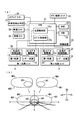
以下、本発明の好適な実施形態を図1から図10に基づいて説明する。各図においては、ドライバーが運転席から見たと仮定した車両及び路面描画用灯具ユニットの各方向を(上方:下方:左方:右方:前方:後方=Up:Lo:Le:Ri:Fr:Re)として説明する。 Hereinafter, a preferred embodiment of the present invention will be described with reference to FIGS. In each figure, the directions of the vehicle and the road surface drawing lamp unit assumed to be viewed from the driver's seat by the driver (upward: downward: leftward: rightward: forward: backward = Up: Lo: Le: Ri: Fr: Re).
図1に示す車両1は、右前照灯2と左前照灯3を有する。右前照灯2には、第1光源ユニット4が設けられ、左前照灯3には、第2光源ユニット5が設けられる。第1及び第2光源ユニット(4,5)は、左右対称となる形状を有する。図2に示す右前照灯2の第1光源ユニット4は、スイブルユニット6と、スイブルユニット6を揺動可能に保持するブラケット7によって構成される。ブラケット7は、右前照灯2の内側に形成される灯室(図示せず)に固定され、スイブルユニット6は、中心軸線L0を中心として左右に揺動可能に保持される。
A
図2に示すスイブルユニット6は、ユニット本体8、第1光源9、レーザー光源10、樹脂等でそれぞれ成形された第1リフレクター11及び第2リフレクター12を有する。第1光源9とレーザー光源10は、ユニット本体8の上面8aにおいて左右に配置される。第1リフレクター11は、第1光源9の後方から上方を覆うようにユニット本体8の上面8aに一体に形成され、第2リフレクター12は、第1リフレクター11に隣接して形成されると共にレーザー光源10の後方から上方を覆うようにユニット本体8の上面8aに一体に形成される。
The
図3(a)に示す第1光源9は、基板9bに搭載された青色のLED発光素子9aを有する。LED発光素子9aによって発生した光B1は、黄色の蛍光体9cを通過して白色化され、第1リフレクター11の内側に銀蒸着等を施して形成された反射面11aによって前方に反射され、白色配光パターンである図4(b)の拡散部WB1を車両1の前方に形成する。
The first
また、図3(b)に示す第2光源であるレーザー光源10は、基板10bに搭載された青色のレーザー発光素子10aを有する。レーザー発光素子10aによって発生した光B2は、集光レンズ10eによって集光された後、キャップ10cの蛍光体10dを通過して白色化され、第2リフレクター12の内側に銀蒸着等を施して形成された反射面12aによって前方に反射され、白色配光パターンである図4(b)の集光部CB1を拡散部の内側に形成する。尚、第1光源9には、レーザー光源10よりも輝度の低い拡散部を形成するものであれば、LED発光素子以外の放電灯バルブやハロゲンバルブ等を採用しても良い。
A
図2のブラケット7は、前後に貫通する箱形状を有し、左右に設けられた取付部(7a〜7c)によって右前照灯2の灯室(図示せず)に取り付けられ、スイブルユニット6は、ブラケット7の内部7dに配置される。スイブルユニット6は、ユニット本体8の下方に突出し、ユニット本体8の内側のスイブル駆動源(スイブルモーター等)によってユニット本体8に対して回動する駆動軸6aと、第1及び第2リフレクター(11,12)の境界位置に設けられてブラケット7に回動自在に保持される被保持軸6bによってブラケット7の内部7aに保持される。被保持軸6bと同軸に配置される駆動軸6aは、ブラケット7に固定され、スイブルユニット6は、スイブル駆動源の駆動によって中心軸線L0を中心として左右に揺動する。
The
また、図3(c)は、スイブルユニット6の変形例であるスイブルユニット16を示す。スイブルユニット16は、スイブルユニット6の第1及び第2リフレクター(11,21)を一のリフレクター14に集約することにより、第1光源19とレーザー光源15に使用するリフレクターを兼用させたものである。複数の第1光源19は、それぞれ第1光源と同一の構成を有するLED光源であり、レーザー光源15は、レーザー光源10と同一の構成を有する。複数の第1光源19は、ユニット本体18の上面18aにおいて、レーザー光源15を取り囲むように配置され、第1光源19及び複数のレーザー光源15から出射される白色光は、共にリフレクター14の内側に銀蒸着等で形成した反射面14aによって前方に反射され、図4(b)の拡散部WB1及び集光部CB1からなる配光パターンAB1を車両の前方に形成する。スイブルユニット16は、ユニット本体18の内側に設けられたスイブル駆動源(スイブルモーター等)の駆動軸16aと、リフレクター14の上方に突出する被保持軸16bによってブラケット7に保持され、スイブルユニット16は、スイブルモーターの駆動によって中心軸線L0を中心として左右に揺動する。スイブルユニット16は、左右の光源ユニットにおいて同じスイブルユニット16を採用出来るため、図2のスイブルユニット6及びスイブルユニットに対して左右対象となる(左前照灯3用の)スイブルユニット(図示せず)を採用するよりもコストダウンを計ることが出来る。
FIG. 3C shows a
次に図4(a)によって右前照灯2の第1光源ユニット4及び左前照灯3の第2光源ユニット5の双方を制御する制御装置20について説明する。制御装置20は、ECU21と、ROM22、RAM23を有し、ECU21は、各光源の点灯及び消灯を制御する光源制御部21aと、第1及び第2光源ユニット(4,5)のスイブル駆動源を制御するスイブル制御部21bを有する。ROM22には、RAM23において実行されるECU21の制御プログラムが記憶され、ECU21には、車載カメラ25、車速センサー26、自車両検出手段27(操舵角センサー、加速度センサー、GPS、カーナビゲーションシステム等)、ステアリングセンサー34,AFS(Adaptive Front-lighting System)の解除スイッチ35等が接続される。
Next, a
右前照灯2の第1光源ユニット4は、第1光源9とレーザー光源10の他、右点灯制御回路28と、右スイブル駆動源29とを有する。また、左前照灯3の第2光源ユニット5は、第1光源30(LED光源)、レーザー光源31、左点灯制御回路32及び左スイブル駆動源33を有する。ECU21の光源制御部21aは、右点灯制御回路28を介して第1光源9及びレーザー光源10に接続され、かつ左点灯制御回路32を介して第1光源30及びレーザー光源31に接続される。また、ECU21のスイブル制御部21bは、右スイブル駆動源29及び左スイブル駆動源33にそれぞれ接続される。
The first
ECU21は、車載カメラ25、車速センサー26等によって検出される先行車両または対向車両の位置及び車速等、または自車両検出手段27、ステアリングセンサー34等によって検出される自車両の位置及び車速等と、ROM22の制御プログラムに基づいて、右及び左の点灯制御回路(28,32)とスイブル駆動源(29,33)を制御し、右及び左の第1光源(9,30)及びレーザー光源(10、31)をそれぞれ独立して点灯または消灯させると共に右前照灯2の第1光源ユニット4のスイブルユニット6と、左前照灯3の第2光源ユニット5のスイブルユニット(図示せず)をそれぞれ車両の左右方向いずれかに揺動させる。
The
図4(b)に示すように、右前照灯2の第1光源ユニット4は、第1光源9(LED光源)によって形成される拡散部WB1と、レーザー光源10によって拡散部WB1の内側に形成される、拡散部WB1より輝度の高い集光部CB1による右配光パターンAB1を車両の前方に形成する。また、左前照灯3の第2光源ユニット5は、第1光源30(LED光源)によって形成される拡散部WB2と、レーザー光源31によって拡散部WB2の内側に形成される、拡散部WB2より輝度の高い集光部CB2による左配光パターンAB2を車両の前方に形成する。右及び左の配光パターン(AB1,AB2)は、合成配光パターンを形成することによって車両の前方を照明し、第1光源(9,30)による拡散部(WB1,WB2)は、車両前方の路面等を広範囲に照明し、集光部(CB1,CB2)は、例えば車両から前方に数百メートル離れた領域等、拡散部(WB1,WB2)が到達しない遠方領域の路面等を限定的に照明する。
As shown in FIG. 4B, the first
次に車両用前照灯の制御方法の第1実施例〜第3実施例を説明する。図5(a)及び図5(b)は、図1の右前照灯2による配光パターンAB1を示し、図5(c)は、右及び左前照灯(2,3)による合成配光パターン(AB1、AB2)を示し、各図の二点鎖線部分は、配光パターンの拡散部または集光部の減光または消灯状態を示す。尚、図5(a)〜図5(c)は、車両前方の所定位置(例えば、車両から前方に25m離れた位置等。尚、車両から前方までの距離は25mに限られない。)に配置された仮想鉛直スクリーン上に形成される配光パターンを透視的に示す図である。
Next, first to third embodiments of the vehicle headlamp control method will be described. 5A and 5B show a light distribution pattern AB1 by the
図5(a)に示す、第1実施例の車両前照灯の制御方法は、配光パターンAB1のうち、第1光源(LED光源)9の故障などによって拡散部WB1が点灯不能状態になってしまった場合、拡散部WB1よりも輝度の高い集光部CB1を形成するレーザー光源10についてもまた減光または消灯するという制御により、車両のドライバーや歩行者を幻惑させないための制御である。具体的には、図4(a)に示す第1光源9(LED光源)による拡散部WB1の点灯不能状態が右点灯制御回路28において検出された場合において、ECU21が、集光部CB1を減光または消灯するようにレーザー光源10を制御する。尚、ECU21によるこの制御は、左前照灯3の第2光源ユニット5においても同様に行われ、右及び左前照灯(2,3)の制御は、独立して行われるようにする。
In the vehicle headlamp control method according to the first embodiment shown in FIG. 5A, the diffusing portion WB1 becomes unlit due to a failure of the first light source (LED light source) 9 in the light distribution pattern AB1. In such a case, the
また、図5(b)及び図6(a)に示す、第2実施例の車両前照灯の制御方法は、配光パターンAB1のうち、レーザー光源10の故障等によって集光部CB1が点灯不能になり、拡散部WB1が到達しない遠方領域の路面等が照明されなくなっても、拡散部WB1による車両前方の所定範囲の照明を継続させるための制御である。具体的には、点灯中のレーザー光源10による集光部CB1の点灯不能状態が図4(a)の右点灯制御回路28において検出された場合(図6(a)の符号36を参照)であっても、ECU21は、第1光源(LED光源)9による拡散部WB1の点灯を維持するように制御する(符号37を参照)。尚、集光部CB1を形成するレーザー光源10が点灯不能になった第1光源ユニット4は、車両1を停止させて第1光源9を消灯させた場合、第1光源9を再点灯させないことによって、速やかにレーザー光源10の修理を促すことが望ましい。具体的には、車両を停止させて第1光源9を消灯した後、車両の始動時に故障したレーザー光源10を有する第1光源ユニット4を点灯させようとした際に、集光部CB1の点灯不能状態が右点灯制御回路28において検出された場合(図6(a)の符号36を参照)、ECU21は、第1光源(LED光源)9による拡散部WB1の消灯を維持するように制御する(符号38を参照)。尚、ECU21によるこの制御は、左前照灯3の第2光源ユニット5においても同様に行われ、右及び左前照灯(2,3)の制御は、独立して行われるようにする。
Further, in the vehicle headlamp control method of the second embodiment shown in FIGS. 5B and 6A, the condensing part CB1 is turned on due to a failure of the
次に、図5(c)、図6(b)により、第3実施例の車両用前照灯の制御方法を説明する。第3実施例の車両前照灯の制御方法は、合成配光パターン(AB1、AB2)のうち、レーザー光源(10、31)のいずれかの故障等によって点灯中の集光部(CB1,CB2)のうち一方が点灯不能になってしまった場合、点灯中のもう一方の集光部も減光または消灯することにより、合成配光パターン(AB1、AB2)の形崩れを防止する制御である。具体的には、例えば、右前照灯2のレーザー光源10の故障等により集光部CB1の点灯不能状態が図4(a)の右点灯制御回路28において検出された場合において(図6(b)の符号40を参照)、ECU21は、左点灯制御回路32を介して点灯中の集光部CB2を減光または消灯するようにレーザー光源31を制御し(符号41を参照)、左前照灯3のレーザー光源31の故障等により集光部CB2の点灯不能状態が左点灯制御回路32において検出された場合において(符号40を参照)、ECU21は、右点灯制御回路28を介して点灯中の集光部CB1を減光または消灯するようにレーザー光源10を制御する(符号41を参照)。
Next, a method for controlling the vehicle headlamp according to the third embodiment will be described with reference to FIGS. 5C and 6B. The control method of the vehicle headlamp according to the third embodiment is as follows. The condensing units (CB1, CB2) that are turned on due to a failure of one of the laser light sources (10, 31) in the combined light distribution patterns (AB1, AB2). ), The other light-collecting part that is lit is dimmed or extinguished to prevent the composite light distribution pattern (AB1, AB2) from being deformed. . Specifically, for example, when the lighting failure state of the light condensing unit CB1 is detected in the right
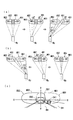
次に、図7(a)から図7(f)により、第4実施例の車両用前照灯の制御方法を説明する。尚、図7(a)〜図7(f)は、車両前方の所定位置(例えば、車両から前方に25m離れた位置等。尚、車両から前方までの距離は25mに限られない。)に配置された仮想鉛直スクリーン上に形成される配光パターンを透視的に示す図である。第4実施例の車両用前照灯の制御方法は、配光可変型の車両用前照灯において、先行車両や対向車両が検出された際に高輝度の集光部(CB1,CB2)が検出された先行車両や対向車両にできる限り照射されないように合成配光パターン(AB1,AB2)を移動させ、かつ集光部(CB1,CB2)を減光または消灯させる制御方法である。図7(a)から図7(f)において、集光部(CB1,CB2)の実線部分は、点灯状態を示し、二点鎖線部分は、減光または消灯状態を示す。例えば、図7(a)に示すように自車両(図示せず)の前方において対向車線OR1を走行する対向車両Ot1が、図4(a)の車載カメラ25によって検出された場合、ECU21は、車載カメラ25と車速センサー26によって検出される対向車両Ot1の位置及び速度に基づいてスイブル駆動源(28,33)をそれぞれ駆動させる。その際ECU21は、図7(b)に示すように、右配光パターンAB1の照射範囲が対向車両Ot1の位置に重ならないように第1光源ユニット4(のスイブルユニット6。以下は単に第1光源ユニット4とする)を右に揺動させ、かつ図7(b)に示すように左配光パターンAB2の照射範囲が対向車両Ot1の位置に重ならなくなるまで第2光源ユニット5(の図示しないスイブルユニット。以下は単に第2光源ユニット5する)を左に揺動させる。
Next, a control method for the vehicle headlamp according to the fourth embodiment will be described with reference to FIGS. 7A to 7F show predetermined positions in front of the vehicle (for example, a position 25 m away from the vehicle forward, etc. Note that the distance from the vehicle to the front is not limited to 25 m). It is a figure which shows in perspective the light distribution pattern formed on the arrange | positioned virtual vertical screen. In the vehicle headlamp control method according to the fourth embodiment, in the variable light distribution vehicle headlamp, when the preceding vehicle or the oncoming vehicle is detected, the high-intensity condensing units (CB1, CB2) are provided. In this control method, the combined light distribution pattern (AB1, AB2) is moved so that the detected preceding vehicle and the oncoming vehicle are not irradiated as much as possible, and the light collecting units (CB1, CB2) are dimmed or turned off. In FIG. 7A to FIG. 7F, the solid line portions of the light collectors (CB1, CB2) indicate the lighting state, and the two-dot chain line portion indicates the dimming or extinguishing state. For example, when an oncoming vehicle Ot1 traveling in an oncoming lane OR1 in front of the host vehicle (not shown) as shown in FIG. 7A is detected by the in-vehicle camera 25 in FIG. The swivel drive sources (28, 33) are driven based on the position and speed of the oncoming vehicle Ot1 detected by the in-vehicle camera 25 and the vehicle speed sensor 26, respectively. At this time, as shown in FIG. 7B, the
また、図7(c)に示すように、右方向に揺動する第1光源ユニット4が、車両の前後方向に対して揺動可能な最大角である揺動限界角αまで揺動した場合、第1光源ユニット4は、対向車両Ot1を避けるように右配光パターンAB1を更に右方向に移動させることが出来ず、対向車両Ot1は、再び右配光パターンAB1の照射を受ける。そこで、図7(c)に示すようにECU21は、第1光源ユニット4の揺動角が揺動限界角αに達した場合、集光部(CB1、CB2)の双方を消灯する。その結果、図7(d)に示すように、右配光パターンAB1の照射範囲に再び入った対向車両Ot1のドライバーは、拡散部WB1よりも輝度の高いレーザー光による集光部CB1の照射を受けないため、まぶしさで幻惑されにくくなり、集光部CB2のみが点灯することによる配光パターンの形崩れも発生しなくなる。
In addition, as shown in FIG. 7C, when the first
また、図7(e)に示すように、対向車両Ot1の通過後、ECU21は、集光部(CB1,CB2)を消灯したまま、第1光源ユニット4を左に揺動させ、かつ第2光源ユニット5を右に揺動させることにより、第1及び第2光源ユニット(4,5)を対向車両Ot1を検出する前の初期位置(図7(f)の位置)まで戻した後、レーザー光源(10,31)を制御して再び集光部(CB1,CB2)を点灯させる。その際、第1及び第2光源ユニット(4,5)を対向車両Ot1を検出する前の初期位置(図7(f)の位置)まで戻す際に、自車両のドライバーは、消灯された集光部(CB1,CB2)を視認せず、集光部より輝度の低い拡散部(WB1,WB2)の移動のみを視認するため、不必要な視線誘導を受けにくい。
Further, as shown in FIG. 7 (e), after passing the oncoming vehicle Ot1, the
次に、図8(a)と図8(b)により、第5実施例の車両用前照灯の制御方法と、制御方法の変形例を説明する。第5実施例の車両前照灯の制御方法は、減光または消灯中の配光パターンにおいて、拡散部に対する集光部の輝度差を生じにくくして配光ムラの発生を防止することによって合成配光パターンを見た車両のドライバー等を幻惑させにくくする制御方法である。図8(a)〜図8(c)のグラフは、横軸が経過時間tを示し、縦軸が集光部(CB1,CB2)及び拡散部(WB1,WB2)の輝度cdを示す。各グラフの一点鎖線は、図4(b)の集光部(CB1,CB2)の輝度の変化を示し、二点鎖線は、拡散部(WB1,WB2)の輝度の変化を示す。尚、拡散部(WB1,WB2)及び集光部(CB1,CB2)のそれぞれの輝度は、例えば、図4(a)に示す車載カメラ25の映像をECU21で解析することによって検出されるようにする。 Next, referring to FIGS. 8A and 8B, a control method for a vehicle headlamp according to a fifth embodiment and a modification of the control method will be described. The control method of the vehicle headlamp according to the fifth embodiment is combined by preventing the occurrence of uneven light distribution by making it difficult to produce a luminance difference between the light collecting portion and the light diffusing portion in a light distribution pattern that is dimmed or turned off. This is a control method that makes it difficult for the driver of the vehicle who sees the light distribution pattern to be dazzled. In the graphs of FIG. 8A to FIG. 8C, the horizontal axis indicates the elapsed time t, and the vertical axis indicates the luminance cd of the light collecting portions (CB1, CB2) and the diffusion portions (WB1, WB2). A one-dot chain line in each graph indicates a change in luminance of the light collecting portions (CB1, CB2) in FIG. 4B, and a two-dot chain line indicates a change in luminance in the diffusion portions (WB1, WB2). In addition, each brightness | luminance of a spreading | diffusion part (WB1, WB2) and condensing part (CB1, CB2) is detected, for example by analyzing the image | video of the vehicle-mounted camera 25 shown to Fig.4 (a) by ECU21. To do.
第5実施例の車両前照灯の制御方法においては、図8(a)に示すように、輝度Cd1の拡散部(WB1,WB2)と、輝度Cd2の集光部(CB1,CB2)によって、図4(b)の合成配光パターン(AB1,AB2)を車両1の前方に形成する。合成配光パターン(AB1,AB2)を減光または消灯させる場合、まず、ECU21は、拡散部(WB1,WB2)の輝度Cd1を維持しつつ、集光部(CB1,CB2)を減光させるように第1光源(9,30)とレーザー光源(10,31)をそれぞれ制御する。時間t1において、集光部(CB1,CB2)の輝度が拡散部(WB1,WB2)の輝度Cd1と同一またはほぼ同一するまで低下すると、ECU21は、第1光源(9,30)を制御して拡散部(WB1,WB2)の減光または消灯を開始する。また、ECU21は、レーザー光源(10,31)を制御し、拡散部(WB1,WB2)の輝度を超えないように集光部(CB1,CB2)を減光させる。その結果、合成配光パターン(AB1,AB2)は、拡散部(WB1,WB2)及び集光部(CB1,CB2)部の間に生じる輝度差を低減された状態で減光または消灯する。
In the vehicle headlamp control method of the fifth embodiment, as shown in FIG. 8 (a), by means of a diffusion unit (WB1, WB2) with luminance Cd1 and a condensing unit (CB1, CB2) with luminance Cd2. The combined light distribution pattern (AB1, AB2) of FIG. 4B is formed in front of the
また、図8(b)は、第5実施例の車両用前照灯の制御方法の変形例を示すものである。図8(b)の制御方法は、合成配光パターン(AB1,AB2)を減光または消灯させる場合において、集光部(CB1,CB2)の減光開始後、集光部(CB1,CB2)の輝度がCd2から拡散部(WB1,WB2)の輝度Cd1まで低下する前に拡散部(WB1,WB2)の減光を開始させると共に、集光部(CB1,CB2)の輝度の低下速度が拡散部(WB1,WB2)の輝度の低下速度よりも早くなるように第1光源(9,30)とレーザー光源(10,31)を制御する方法である。集光部(CB1,CB2)の輝度は、時間t2において減光中の拡散部(WB1,WB2)の輝度と一致するため、減光中の集光部(CB1,CB2)は、減光中の拡散部(WB1,WB2)に対して輝度差を生じにくくなる。 FIG. 8B shows a modification of the vehicle headlamp control method of the fifth embodiment. In the control method of FIG. 8B, in the case where the combined light distribution pattern (AB1, AB2) is dimmed or extinguished, after the dimming of the condensing units (CB1, CB2) is started, the condensing units (CB1, CB2). Before the brightness of Cd2 decreases from the brightness Cd1 to the brightness Cd1 of the diffusing unit (WB1, WB2), the dimming of the diffusing unit (WB1, WB2) is started, and the decreasing rate of the brightness of the condensing unit (CB1, CB2) In this method, the first light source (9, 30) and the laser light source (10, 31) are controlled so as to be faster than the luminance decrease rate of the parts (WB1, WB2). Since the brightness of the light collecting parts (CB1, CB2) matches the brightness of the diffusing parts (WB1, WB2) that are dimming at time t2, the light collecting parts (CB1, CB2) that are dimming are dimmed. The luminance difference is less likely to occur with respect to the diffusion parts (WB1, WB2).
図8(c)は、第6実施例の車両用前照灯の制御方法を示すものであり。図8(c)の制御方法は、消灯中の右及び左前照灯(2,3)による点灯を開始する際に拡散部に対する集光部の輝度差を生じにくくして配光ムラを防止するための制御方法である。ECU21は、まず、第1光源(9,30)の点灯開始後の時間t3においてレーザー光源(10,31)の点灯を開始させるように制御を行う。また、ECU21は、拡散部(WB1,WB2)が最大輝度Cd1に達する時間t4において集光部(CB1,CB2)の輝度が一致するような速度で集光部(CB1,CB2)を増光させるようにレーザー光源(10,31)を制御する。この場合、合成配光パターン(AB1,AB2)においては、拡散部(WB1,WB2)が点灯を開始してから最大輝度Cd1に達するまでの間に集光部(CB1,CB2)との間に輝度差が生じにくくなるため、前照灯(2,3)を点灯する際に合成配光パターン(AB1,AB2)の配光ムラが生じにくくなる。
FIG. 8C shows a control method for the vehicle headlamp according to the sixth embodiment. The control method shown in FIG. 8C prevents uneven light distribution by making it difficult to produce a luminance difference between the condensing unit and the diffusing unit when starting lighting with the right and left headlamps (2, 3) being turned off. Is a control method. First, the
次に、図9(a)及び図9(b)により、第7実施例の車両用前照灯の制御方法を説明する。第7実施例の車両用前照灯の制御方法は、配光可変型の車両用前照灯において、合成配光パターン(AB1,AB2)を一体として移動させる際に集光部(CB1,CB2)が左右に分離され、ドライバーの視線が不必要に誘導されることによって幻惑されることを防止する制御方法である。 Next, a control method for a vehicle headlamp according to a seventh embodiment will be described with reference to FIGS. 9A and 9B. In the vehicle headlamp control method of the seventh embodiment, in the variable light distribution vehicle headlamp, when the combined light distribution pattern (AB1, AB2) is moved as a unit, the condensing units (CB1, CB2). Is a control method that prevents the driver's line of sight from being dazzled by unnecessary guidance.
図9(a)は、合成配光パターン(AB1,AB2)を車両の右方向に移動する際の制御方法であり、各図の二点鎖線部分は、集光部(CB1,CB2)の減光または消灯を示す。まず、例えば、図4(a)に示す車載カメラ25や自車両検出手段27のカーナビゲーションシステム等によって道路の形状が右方向にカーブしていることを検出したり、ステアリングセンサー34によって右方向への操舵を検出した場合、ECU21は、スイブル制御部21bを介して右及び左のスイブル駆動源(29,33)を制御し、第1及び第2光源ユニット(4,5)を同期してカーブする道路に沿って右方向(Ri方向)に揺動させることにより、形状を維持した合成配光パターン(AB1,AB2)を右方向(Ri方向)に移動させる。一方、左前照灯3の第2光源ユニット5は、車両1の内部の他部材等への干渉を防止する観点から車両の内方向(右方向)への揺動を制限される。従って、第2光源ユニット5の右方向への揺動限界角β1、即ち、車両の前後方向に伸びる軸線L1に対して揺動可能な最大角度β1は、第1光源ユニット4の右方向への揺動限界角よりも小さいため、第2光源ユニット5の揺動限界角β1を越えて第1光源ユニット4を右方向に揺動させた場合、右配光パターンAB1の集光部CB1は、左配光パターンAB2の集光部CB1から右方向に分離する。
FIG. 9 (a) shows a control method for moving the combined light distribution pattern (AB1, AB2) in the right direction of the vehicle. The two-dot chain line portion in each figure represents the reduction of the light converging parts (CB1, CB2). Indicates light or light extinction. First, for example, the in-vehicle camera 25 shown in FIG. 4A or the car navigation system of the own
そこで、図9(a)の右図に示すように、ECU21は、第2光源ユニット5の揺動角が右方向への揺動限界角β1に達した際に、左点灯制御回路32を介してレーザー光源31を制御することによって、左集光部CB2を減光または消灯させる。その結果、第1光源ユニット4の右方向への揺動角γ1が第2光源ユニット5の右方向への揺動限界角β1を越えてγ1>β1となっても、集光部(CB1,CB2)の左右方向への分離が自車両Myのドライバーに視認されにくくなる。言い換えると、仮に点灯を続けていればドライバーの視線を道路の湾曲方向と逆方向の左方向に誘導する可能性のある左集光部CB2が、自車両Myのドライバーに視認されにくくなるため、ドライバーが幻惑されにくくなる。
Therefore, as shown in the right diagram of FIG. 9A, the
一方、図9(b)は、車載カメラ25によって自車両Myの進行方向の道路(図示せず)が左方向にカーブしていることを検出した場合、合成配光パターン(AB1,AB2)を車両の左方向に移動する際の制御方法である。例えば、図4(a)に示す車載カメラ25や自車両検出手段27のカーナビゲーションシステム等によって道路の形状が左方向にカーブしていることを検出したり、ステアリングセンサー34によって左方向への操舵を検出した場合、ECU21は、第1及び第2光源ユニット(4,5)をカーブする道路に沿って左方向に揺動させ、形状を維持した合成配光パターン(AB1,AB2)を左方向(Le方向)に移動させる。一方、右前照灯2の第1光源ユニット4は、車両の内方向(左方向)への揺動を制限される。従って、第2光源ユニット5の左方向への揺動限界角β2は、第1光源ユニット4の右方向への揺動限界角よりも小さくなる。
On the other hand, FIG. 9B shows the combined light distribution pattern (AB1, AB2) when the in-vehicle camera 25 detects that the road (not shown) in the traveling direction of the host vehicle My curves to the left. This is a control method when moving in the left direction of the vehicle. For example, the in-vehicle camera 25 shown in FIG. 4A, the car navigation system of the own
そこで、図9(b)の左図に示すように、ECU21は、第2光源ユニット5の揺動角が左方向への揺動限界角β2に達した際に、レーザー光源10を制御して、右集光部CB1を減光または消灯させる。その結果、第2光源ユニット5の左方向への揺動角γ2が第1光源ユニット4の左方向への揺動限界角β2を越えてγ2>β2となっても、集光部(CB1,CB2)の左右方向への分離が自車両Myのドライバーに視認されにくくなる。言い換えると、仮に点灯を続けていればドライバーの視線を道路の湾曲方向と逆方向の左方向に誘導する可能性のある右集光部CB1が、自車両Myのドライバーに視認されにくくなるため、ドライバーが幻惑されにくくなる。
Therefore, as shown in the left diagram of FIG. 9B, the
次に、図9(c)、図10(a)及び(b)により、第8実施例の車両用前照灯の制御方法を説明する。第8実施例の車両用前照灯の制御方法は、配光可変型の車両用前照灯において、合成配光パターン(AB1,AB2)を一体として移動させる際に集光部(CB1,CB2)が左右に分離され、ドライバーの視線が不必要に誘導されることによって幻惑されることを防止する制御方法である。 Next, the control method for the vehicle headlamp of the eighth embodiment will be described with reference to FIGS. 9C, 10A and 10B. In the vehicle headlamp control method of the eighth embodiment, in the variable light distribution vehicle headlamp, when the combined light distribution pattern (AB1, AB2) is moved as a unit, the condensing units (CB1, CB2). Is a control method that prevents the driver's line of sight from being dazzled by unnecessary guidance.
第8実施例の車両用前照灯の制御方法は、いわゆるハンチング現象を防止するための制御方法である。ハンチング現象とは、例えば、図9(c)に示すように、車載カメラ等によって自車両の前方車両である対向車両Ot1や先行車両(図示せず)が検出された際に、第1光源9及びレーザー光源10を消灯(または減光)させることによって検出された対向車両Ot1への右配光パターンAB1の照射を停止(または低減)させ、更に対向車両Ot1が検出されなくなった際に消灯(または減光)していた第1光源9及びレーザー光源10を再点灯(または増光)させて、右配光パターンAB1を対向車両Ot1が存在していた位置に再び照射する制御を行う車両用前照灯の制御において、看板等の路上設置物によって反射された前照灯の反射光を他の車両と誤検出することによる各光源の消灯と、前記反射光が消滅したことによる再点灯を繰り返す現象をいう。
The control method for the vehicle headlamp according to the eighth embodiment is a control method for preventing a so-called hunting phenomenon. For example, as shown in FIG. 9C, the hunting phenomenon refers to the first
第8実施例の車両用前照灯の具体的な制御方法を図10(a)及び図10(b)によって説明する。第8実施例においては、図9(c)の対向車線OR1上またはその近傍に対向車両Ot1や看板などの路上物体が検出された際の右配光パターンAB1の制御を一例として説明しているが、自車両(図示せず)の走行車線OM1上またはその近傍において先行車両(図示せず)や看板などの路上物体が検出された際の左配光パターンAB2の制御もまた同様に行われる。また、図10(a)及び図10(b)の制御は、交互に行われる。まず、ECU21は、図4(a)の車載カメラ25,車速センサー26,自車両検出手段27(操舵角センサー、加速度センサー、GPS、カーナビゲーションシステム等)によって、自車両の位置データを取得する(図10(a)の符号46を参照)。
A specific control method for the vehicle headlamp of the eighth embodiment will be described with reference to FIGS. 10 (a) and 10 (b). In the eighth embodiment, control of the right light distribution pattern AB1 when an on-road object such as the oncoming vehicle Ot1 or a signboard is detected on or near the oncoming lane OR1 in FIG. 9C is described as an example. However, control of the left light distribution pattern AB2 when a road vehicle such as a preceding vehicle (not shown) or a signboard is detected on or near the travel lane OM1 of the host vehicle (not shown) is also performed. . Moreover, the control of FIG. 10A and FIG. 10B is performed alternately. First, the
右配光パターンAB1が減光されること無く点灯されている場合において、路上物体(図9(c)では、対向車両Ot1)の光が前方車両として車載カメラ25等によって検出された場合(図10(a)の符号47を参照)、ECU21は、後述する方法によってハンチング現象の判定48を行う。ハンチング現象が発生していない場合、ECU21は、検出された路上物体を前方車両と判定し、第1光源9とレーザー光源10の双方を減光または消灯する制御(遮光実施制御49)を行って、図9(c)において対向車両Ot1に照射されている右配光パターンAB1を減光または消灯させる。その後、図10(b)の制御を行い、前方車両が検出できなくなった場合(符号50を参照)、ECU21は、対向車両Ot1が通過したものと判定し、第1光源9とレーザー光源10の双方を増光または点灯する制御(遮光解除制御52)を行って、右配光パターンAB1を再び元の輝度で点灯させる。
When the right light distribution pattern AB1 is lit without being dimmed, the light of the object on the road (oncoming vehicle Ot1 in FIG. 9C) is detected as a forward vehicle by the vehicle-mounted camera 25 or the like (FIG. The
一方、仮に、車載カメラ25等で検出された路上物体の光が、図9(c)のような対向車両Ot1の前照灯等による光ではなく、第1光源ユニット4から路上の看板等に照射された光による反射光であった場合、ECU21は、図10(a)の遮光実施制御49を行った後、反射光の消滅を対向車両の通過完了と誤認識することによって直ちに図10(b)の遮光解除制御52を行い、更に第1光源ユニット4の再点灯によって再び遮光実施制御49を繰り返すことにより、右配光パターンAB1の点滅を繰り返すハンチング現象を発生させるおそれがある。そこで、ECU21は、路上物体の光を検出した場合、例えば、検出前の所定時間に遮光実施制御49と遮光解除制御52がどの程度繰り返されているか(例えば、1秒間に3回右配光パターンAB1の点消灯が繰り返された場合、それをハンチング現象の発生と判定する等)を基準として、ハンチング判定(48,51)を行う。
On the other hand, suppose that the light of the object on the road detected by the vehicle-mounted camera 25 or the like is not from the headlight of the oncoming vehicle Ot1 as shown in FIG. 9C, but from the first
図10(a)において、右配光パターンAB1が再点灯された状態で路上物体の光が前方車両として車載カメラ25等によって検出され(符号47を参照)、かつハンチング現象が発生していると判定された場合(符号48を参照)、ECU21は、レーザー光源10のみを制御して、図9(c)の右配光パターンAB1の集光部CB1のみを減光または消灯するハンチング処理53を行う。その結果、図10(b)の制御において、路上物体の光の輝度がハンチング処理53を行う前の輝度を一定値以上下回ることで前方車両が検出されなくなったと判定された場合(符号50を参照)、ECU21は、前方車両の検出集光部CB1から看板などへの反射光を前方車両と誤検出したものと改めて判定すること、即ち直前のハンチング判定48が正しかったことを再判定することによってハンチングが終了した場合と同様に(符号51を参照)ハンチング解除処理54及び遮光解除制御52を行うことによって、検出された路上物体を遮光対象から除外し、前方車両と誤検出された路上物体への集光部CB1の照射を再開する。
In FIG. 10A, when the right light distribution pattern AB1 is re-lighted, the light of the object on the road is detected as a forward vehicle by the vehicle-mounted camera 25 or the like (see reference numeral 47), and the hunting phenomenon occurs. If it is determined (see reference numeral 48), the
一方、図10(a)のハンチング処理53を行い、集光部CB1を減光または消灯しても尚、図10(b)の処理において前方車両が検出された場合(符号50及び57を参照)、ECU21は、図10(a)において、第1光源9を制御し、図9(c)の拡散部WB1を減光または消灯するハンチング処理55を行う。この場合、ECU21は、設定された一定の時間経過後に集光部CB1及び拡散部WB1の双方を減光または消灯するハンチング処理(53,55)を解除する図10(b)のハンチング解除処理54と、遮光解除制御52を行うことにより、再び車両前方への右配光パターンAB1の照射を再開させる。
On the other hand, even if the
また、図10(b)において、右配光パターンAB1の集光部CB1及び拡散部WB1の双方が減光または消灯された状態で、ハンチング現象が発生していると判定された場合(符号51を参照)、ECU21は、第1光源9のみを制御して、図9(c)の右配光パターンAB1の拡散部WB1のみを増光または再点灯するハンチング処理56を行う。その結果、図10(b)の制御において、路上物体の光の輝度がハンチング処理53を行う前の輝度を一定値以上下回ることで前方車両が検出されなくなったと判定された場合(符号50を参照)、ECU21は、前方車両の検出集光部CB1から看板などへの反射光を前方車両と誤検出したものと改めて判定すること、即ち直前のハンチング判定48が正しかったことを再判定することによってハンチングが終了した場合と同様に(符号51を参照)ハンチング解除処理54及び遮光解除制御52を行うことによって、検出された路上物体を遮光対象から除外し、前方車両と誤検出された路上物体への集光部CB1の照射を再開する。
In FIG. 10B, when it is determined that the hunting phenomenon has occurred in a state where both the light condensing unit CB1 and the diffusing unit WB1 of the right light distribution pattern AB1 are dimmed or turned off (reference numeral 51). The
一方、図10(b)のハンチング処理56を行い、拡散部WB1のみを点灯しても尚、図10(a)の処理において前方車両が検出された場合(符号47を参照)、ECU21は、第1光源9を制御し、図9(c)の拡散部WB1を再び減光または消灯するハンチング処理55を行う。この場合、ECU21は、設定された一定の時間経過後に集光部CB1及び拡散部WB1の双方を減光または消灯するハンチング処理(53,55)を解除する図10(b)のハンチング解除処理54と、遮光解除制御52を行うことにより、再び車両前方への右配光パターンAB1の照射を再開させる。
On the other hand, even if the
次に、第9実施例の車両用前照灯の制御方法を説明する。配光可変型の車両用前照灯においては、車両の進行方向の道路や道路上の物体を合成配光パターン(AB1,AB2)によっていち早く照明できるようにすれ違い前照灯(ロービーム)の光軸の向きを車両の操舵方向に追随させる光軸変向制御であるAFS(Adaptive Front-lighting System)と同期した制御を行うことがある。AFSと同期した制御においては、合成配光パターン(AB1,AB2)が、車両の操舵方向に向けて操舵角に応じて動かされる。しかし、高速で走行する場合や、左右のカーブが頻繁に繰り返される形状の道路等を走行する場合、AFSと同期した制御は、ドライバーの視線を誘導することで却ってドライバーを幻惑するおそれがある。第9実施例の車両用前照灯の制御方法は、車両の走行状況に応じてAFS制御を自動的にまたは手動で停止させることにより、合成配光パターン(AB1、AB2)の動きも停止させることでドライバーへの幻惑を防止する制御方法である。 Next, a control method for a vehicle headlamp according to a ninth embodiment will be described. In the variable light distribution vehicle headlamp, the optical axis of the low-beam headlight so that the road in the traveling direction of the vehicle and the object on the road can be quickly illuminated by the combined light distribution pattern (AB1, AB2). In some cases, the control is performed in synchronization with an AFS (Adaptive Front-lighting System), which is an optical axis turning control that follows the steering direction of the vehicle in accordance with the steering direction of the vehicle. In the control synchronized with the AFS, the combined light distribution pattern (AB1, AB2) is moved according to the steering angle toward the steering direction of the vehicle. However, when traveling at a high speed or traveling on a road having a shape in which left and right curves are frequently repeated, control synchronized with AFS may cause the driver to be dazzled by guiding the driver's line of sight. In the vehicle headlamp control method according to the ninth embodiment, the movement of the combined light distribution pattern (AB1, AB2) is also stopped by automatically or manually stopping the AFS control according to the traveling state of the vehicle. This is a control method that prevents the driver from being dazzled.
具体的には、まず、図4(a)に示すECU21は、車載カメラ25や自車両検出手段27のカーナビゲーションシステム等の検出結果に基づき、スイブル駆動源(29,33)を制御して第1及び第2光源ユニット(4,5)を揺動させることによってAFSと同期した制御を行う。一方、例えば、左右のカーブが頻繁に繰り返される形状の道路を車載カメラ25や自車両検出手段27のカーナビゲーションシステム等が検出した場合や、走行中の車両が操舵を行った際のステアリングの角加速度により、左右のカーブを頻繁に繰り返す形状の道路を車両が走行していることを検出した場合等や、車速センサー26が自車両の走行速度が所定の速度(例えば、時速60km等)を越えたことを検出した場合等において、ECU21は、スイブル駆動源(29,33)を制御し第1及び第2光源ユニット(4,5)を揺動開始前の初期位置に戻して揺動を自動的に停止させる、光軸変向停止制御を行うようにする。または、ECU21は、高速で走行する車両または左右のカーブが頻繁に繰り返される形状の道路等を走行する車両のドライバーがAFS解除スイッチ35を押した場合においてもECU21が光軸変向停止制御を行うようにする。
Specifically, first, the
尚、AFSが搭載されていない場合においては、ロービームを固定した状態で合成配光パターン(AB1,AB2)を左右に動かすことが出来るように制御してもよい。また、ロービームを固定した状態で合成配光パターン(AB1,AB2)を動かす制御については、専用のスイッチのONまたはOFFによって開始または停止するようにしてもよく、走行条件に応じて制御の停止または開始を自動的に切り替えるようにしてもよい。 When the AFS is not mounted, the combined light distribution pattern (AB1, AB2) may be controlled to move left and right with the low beam fixed. The control for moving the combined light distribution pattern (AB1, AB2) with the low beam fixed may be started or stopped by turning on or off a dedicated switch. You may make it switch a start automatically.
2 車両用右前照灯
3 車両用左前照灯
4 第1光源ユニット
5 第2光源ユニット
9,30 第1光源
10,31 レーザー光源
25 車両検出手段である車載カメラ
26 車両検出手段である車速センサー
AB1 第1配光パターン
AB2 第2配光パターン
WB1 第1配光パターンの拡散部
WB2 第2配光パターンの拡散部
CB1 第1配光パターンの集光部
CB2 第2配光パターンの集光部
β1 第2光源ユニットによる車両内方向への限界揺動角
β2 第1光源ユニットによる車両内方向への限界揺動角
γ1 第1光源ユニットによる車両外方向への揺動角
γ2 第2光源ユニットによる車両外方向への揺動角
2 vehicle
Claims (6)
前記第1光源及びレーザー光源の双方を点灯し、
前記第1光源の消灯開始と異なる時期に前記レーザー光源の消灯を開始させることを特徴とする、車両用前照灯の制御方法。 A first light source that forms a diffusion portion of the combined light distribution pattern, and a laser light source that is a second light source that forms a condensing portion of the combined light distribution pattern by generating light having higher luminance than the first light source; In a method for controlling a vehicle headlamp having
Turn on both the first light source and the laser light source,
A method for controlling a vehicular headlamp, wherein the laser light source is turned off at a different time from the start of turning off the first light source.
光軸の向きの変更後、前記レーザー光源を消灯した状態で前記光軸を変更前の元の向きに復帰させ、
復帰後、前記レーザー光源を再点灯させることを特徴とする請求項1に記載の車両用前照灯の制御方法。 Change the direction of the optical axis of the vehicle headlamp,
After changing the direction of the optical axis, with the laser light source turned off, return the optical axis to the original direction before the change,
2. The vehicle headlamp control method according to claim 1, wherein the laser light source is turned on again after returning.
前記合成配光パターンの集光部の輝度が拡散部の輝度にほぼ一致した際に前記第1光源の減光または消灯を開始させることを特徴とする請求項1に記載の車両用前照灯の制御方法。 Start dimming or turning off the laser light source prior to the first light source,
2. The vehicle headlamp according to claim 1, wherein dimming or extinguishing of the first light source is started when the luminance of the condensing unit of the combined light distribution pattern substantially matches the luminance of the diffusing unit. Control method.
前記第1光源ユニットを車両の外方向に揺動させる際に前記第2光源ユニットを前記第1光源ユニットに追随させて車両の内方向に揺動させると共に、前記第1光源ユニットによる車両の外方向への揺動角が前記第2光源ユニットによる車両の内方向への揺動限界角を越えた際に前記第2光源ユニットのレーザー光源を減光又は消灯させ、
前記第2光源ユニットを車両の外方向に揺動させる際に前記第1光源ユニットを前記第2光源ユニットに追随させて車両の内方向に揺動させると共に、前記第2光源ユニットによる車両の外方向への揺動角が前記第1光源ユニットによる車両の内方向への揺動限界角を越えた際に前記第1光源ユニットのレーザー光源を減光又は消灯させることを特徴とする、請求項1記載の車両用前照灯の制御装置。 A first light distribution pattern that includes both the first light source and the laser light source and is formed by a first light source unit that can swing in a vehicle width direction; and both the first light source and the laser light source, A second light distribution pattern formed by a second light source unit arranged in the vehicle width direction with respect to the one light source unit and swingable in the vehicle width direction independently of the first light source unit. Swing the combined light distribution pattern in the width direction of the vehicle,
When the first light source unit is swung outwardly of the vehicle, the second light source unit is caused to follow the first light source unit to be swung inward of the vehicle, and the first light source unit is moved outside the vehicle. The laser light source of the second light source unit is dimmed or extinguished when a swing angle in the direction exceeds a swing limit angle inward of the vehicle by the second light source unit;
When the second light source unit is swung outwardly of the vehicle, the first light source unit is caused to follow the second light source unit to be swung inward of the vehicle, and the second light source unit is moved outside the vehicle. The laser light source of the first light source unit is dimmed or extinguished when a swing angle in the direction exceeds a swing limit angle in the vehicle inward by the first light source unit. The vehicle headlamp control device according to claim 1.
前記第1処理によって前記路上物が車両として検出された際に前記第1光源及びレーザー光源から前記路上物へ照射される光を減光又は停止させる第2処理と、
車両検出手段で車両の検出が行われない場合に前記第1光源及びレーザー光源の点灯を再開し、再び車両検出手段で車両の検出を行う第3処理と、
前記第1処理から第3処理までの繰り返しが路上設置物の誤検出によって行われたことを判定する第4処理と、
前記第4処理で路上設置物の誤検出があったことを判定された場合に前記レーザー光源から前記路上物へ照射される光の減光または停止させつつ前記第1光源から前記路上物への光の照射を行い、車両検出手段による前記路上物の検出を行う第5処理と、
前記第5処理による路上物の検出結果に応じて前記第1光源及びレーザー光源から前記路上物への光の照射を制御する第6処理と、
を行うことを特徴とした、請求項1に記載の車両用前照灯の制御方法。 A first process for detecting an object on the road by the vehicle detection means;
A second process for dimming or stopping the light emitted from the first light source and the laser light source to the road object when the road object is detected as a vehicle by the first process;
A third process of restarting the lighting of the first light source and the laser light source when vehicle detection is not performed by the vehicle detection means, and detecting the vehicle again by the vehicle detection means;
A fourth process for determining that the repetition from the first process to the third process has been performed by erroneous detection of an installation on the road;
When it is determined in the fourth process that there is an erroneous detection of an object on the road, the light emitted from the laser light source to the object on the road is dimmed or stopped while the first light source is applied to the road object. A fifth process of performing light irradiation and detecting the object on the road by the vehicle detection means;
A sixth process for controlling the irradiation of light on the road object from the first light source and the laser light source according to the detection result of the road object by the fifth process;
The vehicle headlamp control method according to claim 1, wherein:
車両の走行状況に基づいて発せられる外部信号に基づいて前記光軸変向制御を停止させる光軸変向停止制御と、
を行うことを特徴とする、請求項1に記載の車両用前照灯の制御方法。 Optical axis turning control for causing the direction of the optical axis of the vehicle headlamp formed by the first light source and the laser light source to follow the steering direction of the vehicle;
An optical axis turning stop control for stopping the optical axis turning control based on an external signal issued based on a traveling state of the vehicle;
The vehicle headlamp control method according to claim 1, wherein:
Priority Applications (1)
| Application Number | Priority Date | Filing Date | Title |
|---|---|---|---|
| JP2015102077A JP2016215788A (en) | 2015-05-19 | 2015-05-19 | Control method of headlight for vehicle |
Applications Claiming Priority (1)
| Application Number | Priority Date | Filing Date | Title |
|---|---|---|---|
| JP2015102077A JP2016215788A (en) | 2015-05-19 | 2015-05-19 | Control method of headlight for vehicle |
Publications (1)
| Publication Number | Publication Date |
|---|---|
| JP2016215788A true JP2016215788A (en) | 2016-12-22 |
Family
ID=57579355
Family Applications (1)
| Application Number | Title | Priority Date | Filing Date |
|---|---|---|---|
| JP2015102077A Pending JP2016215788A (en) | 2015-05-19 | 2015-05-19 | Control method of headlight for vehicle |
Country Status (1)
| Country | Link |
|---|---|
| JP (1) | JP2016215788A (en) |
Cited By (2)
| Publication number | Priority date | Publication date | Assignee | Title |
|---|---|---|---|---|
| WO2018123429A1 (en) * | 2016-12-28 | 2018-07-05 | 株式会社小糸製作所 | Illumination apparatus |
| US10746368B2 (en) | 2017-05-23 | 2020-08-18 | Stanley Electric Co., Ltd. | Vehicular headlight |
-
2015
- 2015-05-19 JP JP2015102077A patent/JP2016215788A/en active Pending
Cited By (6)
| Publication number | Priority date | Publication date | Assignee | Title |
|---|---|---|---|---|
| WO2018123429A1 (en) * | 2016-12-28 | 2018-07-05 | 株式会社小糸製作所 | Illumination apparatus |
| CN110121444A (en) * | 2016-12-28 | 2019-08-13 | 株式会社小糸制作所 | Lighting device |
| JPWO2018123429A1 (en) * | 2016-12-28 | 2019-10-31 | 株式会社小糸製作所 | Lighting device |
| US10730427B2 (en) | 2016-12-28 | 2020-08-04 | Koito Manufacturing Co., Ltd. | Lighting device |
| CN110121444B (en) * | 2016-12-28 | 2022-08-16 | 株式会社小糸制作所 | Lighting device |
| US10746368B2 (en) | 2017-05-23 | 2020-08-18 | Stanley Electric Co., Ltd. | Vehicular headlight |
Similar Documents
| Publication | Publication Date | Title |
|---|---|---|
| US9878655B2 (en) | Vehicle lamp | |
| US9688184B2 (en) | Vehicle lamp system | |
| RU2475382C2 (en) | Method of controlling automotive system of headlamps and system of headlamps to this end | |
| WO2015005377A1 (en) | Light distribution control method and light distribution control device for vehicular head lamp | |
| JP2008296660A (en) | Headlamp for vehicle | |
| JP2010044925A (en) | Headlight device for vehicle | |
| JP2010162960A (en) | Vehicle headlight device | |
| JP7155124B2 (en) | Lighting units and vehicle headlights | |
| JP5454526B2 (en) | Vehicle light distribution control device and method | |
| JP2011037342A (en) | Vehicular headlight system | |
| WO2013008085A1 (en) | Vehicle light distribution control device and vehicle light distribution control method | |
| JP6288208B1 (en) | Vehicle headlight control device | |
| JP2012162105A (en) | Vehicular headlight device | |
| JP2010235108A (en) | Headlight device for vehicle | |
| JP2015016773A (en) | Light distribution control method of vehicle headlamp and light distribution control device of the same | |
| JP2016215788A (en) | Control method of headlight for vehicle | |
| JP2006273092A (en) | Vehicle headlight system | |
| JP6296734B2 (en) | Lighting control device for vehicle headlamp, vehicle headlamp system | |
| JP6567175B2 (en) | In-vehicle headlamp and in-vehicle headlamp system | |
| JP6314462B2 (en) | Vehicle headlamp | |
| JP2015033954A (en) | Lighting control device of vehicle headlight, vehicle headlight system | |
| JP5529951B2 (en) | Front combination lamp | |
| JP2014168985A (en) | Headlight device for vehicle | |
| JP6815696B2 (en) | Headlights for driving vehicles | |
| JP6866018B2 (en) | Headlights for driving vehicles |