JP2016212101A - Flow reduction system for isotope ratio measurement - Google Patents
Flow reduction system for isotope ratio measurement Download PDFInfo
- Publication number
- JP2016212101A JP2016212101A JP2016090330A JP2016090330A JP2016212101A JP 2016212101 A JP2016212101 A JP 2016212101A JP 2016090330 A JP2016090330 A JP 2016090330A JP 2016090330 A JP2016090330 A JP 2016090330A JP 2016212101 A JP2016212101 A JP 2016212101A
- Authority
- JP
- Japan
- Prior art keywords
- gas
- flow
- bypass
- line
- isotope ratio
- Prior art date
- Legal status (The legal status is an assumption and is not a legal conclusion. Google has not performed a legal analysis and makes no representation as to the accuracy of the status listed.)
- Granted
Links
- 238000005259 measurement Methods 0.000 title claims abstract description 103
- 230000009467 reduction Effects 0.000 title description 3
- 238000000034 method Methods 0.000 claims abstract description 26
- 239000007789 gas Substances 0.000 claims description 517
- 239000012491 analyte Substances 0.000 claims description 99
- 239000012159 carrier gas Substances 0.000 claims description 81
- 230000003287 optical effect Effects 0.000 claims description 30
- 230000001276 controlling effect Effects 0.000 claims description 22
- 238000011010 flushing procedure Methods 0.000 claims description 18
- 238000011049 filling Methods 0.000 claims description 14
- 238000011144 upstream manufacturing Methods 0.000 claims description 10
- 230000004044 response Effects 0.000 claims description 7
- 239000012530 fluid Substances 0.000 claims description 5
- 238000004891 communication Methods 0.000 claims description 4
- 230000001105 regulatory effect Effects 0.000 claims description 4
- 238000002156 mixing Methods 0.000 description 28
- 238000004458 analytical method Methods 0.000 description 15
- 230000008901 benefit Effects 0.000 description 7
- 239000000203 mixture Substances 0.000 description 5
- IJGRMHOSHXDMSA-UHFFFAOYSA-N Atomic nitrogen Chemical compound N#N IJGRMHOSHXDMSA-UHFFFAOYSA-N 0.000 description 4
- 230000008859 change Effects 0.000 description 4
- 238000004949 mass spectrometry Methods 0.000 description 4
- 238000004611 spectroscopical analysis Methods 0.000 description 4
- XLYOFNOQVPJJNP-UHFFFAOYSA-N water Chemical compound O XLYOFNOQVPJJNP-UHFFFAOYSA-N 0.000 description 4
- 238000009792 diffusion process Methods 0.000 description 3
- 230000000694 effects Effects 0.000 description 3
- 230000001965 increasing effect Effects 0.000 description 3
- 230000035945 sensitivity Effects 0.000 description 3
- 230000003595 spectral effect Effects 0.000 description 3
- 239000002699 waste material Substances 0.000 description 3
- XKRFYHLGVUSROY-UHFFFAOYSA-N Argon Chemical compound [Ar] XKRFYHLGVUSROY-UHFFFAOYSA-N 0.000 description 2
- OKTJSMMVPCPJKN-UHFFFAOYSA-N Carbon Chemical compound [C] OKTJSMMVPCPJKN-UHFFFAOYSA-N 0.000 description 2
- 238000010521 absorption reaction Methods 0.000 description 2
- QVGXLLKOCUKJST-UHFFFAOYSA-N atomic oxygen Chemical compound [O] QVGXLLKOCUKJST-UHFFFAOYSA-N 0.000 description 2
- 230000009286 beneficial effect Effects 0.000 description 2
- 229910052799 carbon Inorganic materials 0.000 description 2
- 238000007865 diluting Methods 0.000 description 2
- 229910052734 helium Inorganic materials 0.000 description 2
- 230000001939 inductive effect Effects 0.000 description 2
- 239000011261 inert gas Substances 0.000 description 2
- 238000002307 isotope ratio mass spectrometry Methods 0.000 description 2
- 230000031700 light absorption Effects 0.000 description 2
- 238000012986 modification Methods 0.000 description 2
- 230000004048 modification Effects 0.000 description 2
- 229910052757 nitrogen Inorganic materials 0.000 description 2
- 239000001301 oxygen Substances 0.000 description 2
- 229910052760 oxygen Inorganic materials 0.000 description 2
- 238000012552 review Methods 0.000 description 2
- 238000001179 sorption measurement Methods 0.000 description 2
- 241000894007 species Species 0.000 description 2
- 238000001228 spectrum Methods 0.000 description 2
- 238000012546 transfer Methods 0.000 description 2
- -1 CH 4 Chemical class 0.000 description 1
- 241000169624 Casearia sylvestris Species 0.000 description 1
- 238000002679 ablation Methods 0.000 description 1
- 239000003570 air Substances 0.000 description 1
- 150000001335 aliphatic alkanes Chemical class 0.000 description 1
- 238000013459 approach Methods 0.000 description 1
- 229910052786 argon Inorganic materials 0.000 description 1
- 230000005540 biological transmission Effects 0.000 description 1
- 238000006243 chemical reaction Methods 0.000 description 1
- 238000002485 combustion reaction Methods 0.000 description 1
- 230000000052 comparative effect Effects 0.000 description 1
- 238000009833 condensation Methods 0.000 description 1
- 230000005494 condensation Effects 0.000 description 1
- 238000013461 design Methods 0.000 description 1
- 238000003795 desorption Methods 0.000 description 1
- 238000010790 dilution Methods 0.000 description 1
- 239000012895 dilution Substances 0.000 description 1
- 230000007613 environmental effect Effects 0.000 description 1
- 238000011067 equilibration Methods 0.000 description 1
- 238000005194 fractionation Methods 0.000 description 1
- 239000001307 helium Substances 0.000 description 1
- SWQJXJOGLNCZEY-UHFFFAOYSA-N helium atom Chemical compound [He] SWQJXJOGLNCZEY-UHFFFAOYSA-N 0.000 description 1
- 239000001257 hydrogen Substances 0.000 description 1
- 229910052739 hydrogen Inorganic materials 0.000 description 1
- 125000004435 hydrogen atom Chemical class [H]* 0.000 description 1
- 230000000155 isotopic effect Effects 0.000 description 1
- 238000003754 machining Methods 0.000 description 1
- 238000004519 manufacturing process Methods 0.000 description 1
- 239000000463 material Substances 0.000 description 1
- 239000012528 membrane Substances 0.000 description 1
- 230000003446 memory effect Effects 0.000 description 1
- 239000002184 metal Substances 0.000 description 1
- 229910052751 metal Inorganic materials 0.000 description 1
- 239000002245 particle Substances 0.000 description 1
- 230000008569 process Effects 0.000 description 1
- 238000005086 pumping Methods 0.000 description 1
- 238000011160 research Methods 0.000 description 1
- 238000005070 sampling Methods 0.000 description 1
- 239000000243 solution Substances 0.000 description 1
- 239000000126 substance Substances 0.000 description 1
Images


Classifications
-
- G—PHYSICS
- G01—MEASURING; TESTING
- G01N—INVESTIGATING OR ANALYSING MATERIALS BY DETERMINING THEIR CHEMICAL OR PHYSICAL PROPERTIES
- G01N33/00—Investigating or analysing materials by specific methods not covered by groups G01N1/00 - G01N31/00
- G01N33/0004—Gaseous mixtures, e.g. polluted air
- G01N33/0009—General constructional details of gas analysers, e.g. portable test equipment
- G01N33/0011—Sample conditioning
-
- G—PHYSICS
- G01—MEASURING; TESTING
- G01N—INVESTIGATING OR ANALYSING MATERIALS BY DETERMINING THEIR CHEMICAL OR PHYSICAL PROPERTIES
- G01N21/00—Investigating or analysing materials by the use of optical means, i.e. using sub-millimetre waves, infrared, visible or ultraviolet light
- G01N21/17—Systems in which incident light is modified in accordance with the properties of the material investigated
- G01N21/25—Colour; Spectral properties, i.e. comparison of effect of material on the light at two or more different wavelengths or wavelength bands
- G01N21/31—Investigating relative effect of material at wavelengths characteristic of specific elements or molecules, e.g. atomic absorption spectrometry
- G01N21/35—Investigating relative effect of material at wavelengths characteristic of specific elements or molecules, e.g. atomic absorption spectrometry using infrared light
- G01N21/3504—Investigating relative effect of material at wavelengths characteristic of specific elements or molecules, e.g. atomic absorption spectrometry using infrared light for analysing gases, e.g. multi-gas analysis
-
- G—PHYSICS
- G01—MEASURING; TESTING
- G01F—MEASURING VOLUME, VOLUME FLOW, MASS FLOW OR LIQUID LEVEL; METERING BY VOLUME
- G01F1/00—Measuring the volume flow or mass flow of fluid or fluent solid material wherein the fluid passes through a meter in a continuous flow
-
- G—PHYSICS
- G01—MEASURING; TESTING
- G01J—MEASUREMENT OF INTENSITY, VELOCITY, SPECTRAL CONTENT, POLARISATION, PHASE OR PULSE CHARACTERISTICS OF INFRARED, VISIBLE OR ULTRAVIOLET LIGHT; COLORIMETRY; RADIATION PYROMETRY
- G01J3/00—Spectrometry; Spectrophotometry; Monochromators; Measuring colours
- G01J3/02—Details
-
- G—PHYSICS
- G01—MEASURING; TESTING
- G01N—INVESTIGATING OR ANALYSING MATERIALS BY DETERMINING THEIR CHEMICAL OR PHYSICAL PROPERTIES
- G01N21/00—Investigating or analysing materials by the use of optical means, i.e. using sub-millimetre waves, infrared, visible or ultraviolet light
- G01N21/01—Arrangements or apparatus for facilitating the optical investigation
- G01N21/11—Filling or emptying of cuvettes
-
- G—PHYSICS
- G01—MEASURING; TESTING
- G01N—INVESTIGATING OR ANALYSING MATERIALS BY DETERMINING THEIR CHEMICAL OR PHYSICAL PROPERTIES
- G01N21/00—Investigating or analysing materials by the use of optical means, i.e. using sub-millimetre waves, infrared, visible or ultraviolet light
- G01N21/17—Systems in which incident light is modified in accordance with the properties of the material investigated
- G01N21/25—Colour; Spectral properties, i.e. comparison of effect of material on the light at two or more different wavelengths or wavelength bands
- G01N21/31—Investigating relative effect of material at wavelengths characteristic of specific elements or molecules, e.g. atomic absorption spectrometry
- G01N21/35—Investigating relative effect of material at wavelengths characteristic of specific elements or molecules, e.g. atomic absorption spectrometry using infrared light
-
- G—PHYSICS
- G01—MEASURING; TESTING
- G01N—INVESTIGATING OR ANALYSING MATERIALS BY DETERMINING THEIR CHEMICAL OR PHYSICAL PROPERTIES
- G01N21/00—Investigating or analysing materials by the use of optical means, i.e. using sub-millimetre waves, infrared, visible or ultraviolet light
- G01N21/84—Systems specially adapted for particular applications
- G01N21/85—Investigating moving fluids or granular solids
-
- G—PHYSICS
- G01—MEASURING; TESTING
- G01N—INVESTIGATING OR ANALYSING MATERIALS BY DETERMINING THEIR CHEMICAL OR PHYSICAL PROPERTIES
- G01N27/00—Investigating or analysing materials by the use of electric, electrochemical, or magnetic means
- G01N27/62—Investigating or analysing materials by the use of electric, electrochemical, or magnetic means by investigating the ionisation of gases, e.g. aerosols; by investigating electric discharges, e.g. emission of cathode
-
- G—PHYSICS
- G01—MEASURING; TESTING
- G01N—INVESTIGATING OR ANALYSING MATERIALS BY DETERMINING THEIR CHEMICAL OR PHYSICAL PROPERTIES
- G01N30/00—Investigating or analysing materials by separation into components using adsorption, absorption or similar phenomena or using ion-exchange, e.g. chromatography or field flow fractionation
- G01N30/02—Column chromatography
- G01N30/62—Detectors specially adapted therefor
- G01N30/72—Mass spectrometers
-
- G—PHYSICS
- G01—MEASURING; TESTING
- G01N—INVESTIGATING OR ANALYSING MATERIALS BY DETERMINING THEIR CHEMICAL OR PHYSICAL PROPERTIES
- G01N30/00—Investigating or analysing materials by separation into components using adsorption, absorption or similar phenomena or using ion-exchange, e.g. chromatography or field flow fractionation
- G01N30/02—Column chromatography
- G01N30/62—Detectors specially adapted therefor
- G01N30/74—Optical detectors
-
- G—PHYSICS
- G01—MEASURING; TESTING
- G01N—INVESTIGATING OR ANALYSING MATERIALS BY DETERMINING THEIR CHEMICAL OR PHYSICAL PROPERTIES
- G01N33/00—Investigating or analysing materials by specific methods not covered by groups G01N1/00 - G01N31/00
- G01N33/0004—Gaseous mixtures, e.g. polluted air
-
- G—PHYSICS
- G01—MEASURING; TESTING
- G01N—INVESTIGATING OR ANALYSING MATERIALS BY DETERMINING THEIR CHEMICAL OR PHYSICAL PROPERTIES
- G01N33/00—Investigating or analysing materials by specific methods not covered by groups G01N1/00 - G01N31/00
- G01N33/0004—Gaseous mixtures, e.g. polluted air
- G01N33/0009—General constructional details of gas analysers, e.g. portable test equipment
-
- H—ELECTRICITY
- H01—ELECTRIC ELEMENTS
- H01J—ELECTRIC DISCHARGE TUBES OR DISCHARGE LAMPS
- H01J49/00—Particle spectrometers or separator tubes
- H01J49/02—Details
- H01J49/04—Arrangements for introducing or extracting samples to be analysed, e.g. vacuum locks; Arrangements for external adjustment of electron- or ion-optical components
- H01J49/0422—Arrangements for introducing or extracting samples to be analysed, e.g. vacuum locks; Arrangements for external adjustment of electron- or ion-optical components for gaseous samples
-
- G—PHYSICS
- G01—MEASURING; TESTING
- G01N—INVESTIGATING OR ANALYSING MATERIALS BY DETERMINING THEIR CHEMICAL OR PHYSICAL PROPERTIES
- G01N21/00—Investigating or analysing materials by the use of optical means, i.e. using sub-millimetre waves, infrared, visible or ultraviolet light
- G01N21/01—Arrangements or apparatus for facilitating the optical investigation
- G01N2021/0193—Arrangements or apparatus for facilitating the optical investigation the sample being taken from a stream or flow to the measurement cell
-
- G—PHYSICS
- G01—MEASURING; TESTING
- G01N—INVESTIGATING OR ANALYSING MATERIALS BY DETERMINING THEIR CHEMICAL OR PHYSICAL PROPERTIES
- G01N21/00—Investigating or analysing materials by the use of optical means, i.e. using sub-millimetre waves, infrared, visible or ultraviolet light
- G01N21/17—Systems in which incident light is modified in accordance with the properties of the material investigated
- G01N21/1702—Systems in which incident light is modified in accordance with the properties of the material investigated with opto-acoustic detection, e.g. for gases or analysing solids
- G01N2021/1704—Systems in which incident light is modified in accordance with the properties of the material investigated with opto-acoustic detection, e.g. for gases or analysing solids in gases
-
- G—PHYSICS
- G01—MEASURING; TESTING
- G01N—INVESTIGATING OR ANALYSING MATERIALS BY DETERMINING THEIR CHEMICAL OR PHYSICAL PROPERTIES
- G01N30/00—Investigating or analysing materials by separation into components using adsorption, absorption or similar phenomena or using ion-exchange, e.g. chromatography or field flow fractionation
- G01N30/02—Column chromatography
- G01N30/88—Integrated analysis systems specially adapted therefor, not covered by a single one of the groups G01N30/04 - G01N30/86
- G01N2030/8809—Integrated analysis systems specially adapted therefor, not covered by a single one of the groups G01N30/04 - G01N30/86 analysis specially adapted for the sample
- G01N2030/8868—Integrated analysis systems specially adapted therefor, not covered by a single one of the groups G01N30/04 - G01N30/86 analysis specially adapted for the sample elemental analysis, e.g. isotope dilution analysis
-
- H—ELECTRICITY
- H01—ELECTRIC ELEMENTS
- H01J—ELECTRIC DISCHARGE TUBES OR DISCHARGE LAMPS
- H01J49/00—Particle spectrometers or separator tubes
- H01J49/02—Details
- H01J49/24—Vacuum systems, e.g. maintaining desired pressures
Abstract
Description
本発明は、例えば、同位体比光学分光計及び同位体比質量分光計などの同位体比分析器のためのガス入口システムに関する。本発明は更に、ガスの流れを同位体比分析器に送達するための方法に関する。 The present invention relates to gas inlet systems for isotope ratio analyzers such as, for example, isotope ratio optical spectrometers and isotope ratio mass spectrometers. The invention further relates to a method for delivering a gas stream to an isotope ratio analyzer.
例えば、炭素、水素、酸素、及び窒素などの元素の安定同位体の相対存在度は、種々の環境でわずかながらも著しく変動する。同位体比の決定は、例えば、法医学的、人類学的、生化学的、及び環境上の研究において、ならびに薬品及び食品産業において、また運動競技者の間でのドーピング判定のためにも頻繁に使用される調査手法である。 For example, the relative abundance of stable isotopes of elements such as carbon, hydrogen, oxygen, and nitrogen varies slightly but significantly in various environments. Isotope ratio determinations are frequently used, for example, in forensic, anthropological, biochemical, and environmental studies, as well as in the pharmaceutical and food industries, and for doping determination among athletes. The survey method used.
同位体比分析は、例えば、CO2を含有するガス状試料において、同位体の相対存在度を決定するための手法である。例えば、同位体比分析は、炭素及び酸素、例えば、13C/12C及び/または18O/16Oの同位体比を決定するために使用され得る。同位体比分析は、光学分光分析及び質量分光分析によって最も一般的に行われる。 Isotope ratio analysis is a technique for determining the relative abundance of isotopes in, for example, a gaseous sample containing CO 2 . For example, isotope ratio analysis can be used to determine the isotope ratio of carbon and oxygen, eg, 13 C / 12 C and / or 18 O / 16 O. Isotope ratio analysis is most commonly performed by optical spectroscopy and mass spectrometry.
同位体比分析のためのガス入口システムは、当該技術分野において、特に質量分光計について既知である。同位体比質量分光分析及びガス入口システムの一般概説は、Brenna et al.,Mass Spectrometry Reviews,1997,16:227−258によって提供される。 Gas inlet systems for isotope ratio analysis are known in the art, particularly for mass spectrometers. For a general review of isotope ratio mass spectrometry and gas inlet systems, see Brenna et al. , Mass Spectrometry Reviews, 1997, 16: 227-258.
試料の同位体比の決定は通常、試料ガスと、既知の同位体比を有する1つ以上の基準ガスとの同位体比の比較測定を必要とする。したがって、同位体比分析のためのガス入口システムは通常、分析器の中に試料及び/または基準ガスを提供するための分析物ガス入口と、分析器によって決定予定のガスを通常は含有しない、分析物の伝達を容易にするためのキャリアガスを提供するための、キャリアガス入口と、を備える。 Determination of the isotope ratio of a sample typically requires a comparative measurement of the isotope ratio between the sample gas and one or more reference gases having a known isotope ratio. Thus, a gas inlet system for isotope ratio analysis typically does not contain an analyte gas inlet for providing sample and / or reference gas into the analyzer and a gas to be determined by the analyzer, A carrier gas inlet for providing a carrier gas for facilitating analyte transfer.
同位体比光学(通常、赤外)分光分析(IROS)において、CO2またはH2Oによる光吸収が測定され、同位体組成が、結果として生じるスペクトルから決定される。この手法は、例えば、使用の容易さ、費用、及び可搬性に起因して、質量分光分析に勝る利点がある。更に、IROSは、H2Oの直接分析を可能にするのに対して、同位体比質量分光分析は、分析の前に、例えば、H2もしくはCO2へのH2Oの変換、またはCO2との平衡化を必要とする。 In isotope ratio optical (usually infrared) spectroscopy (IROS), light absorption by CO 2 or H 2 O is measured and the isotopic composition is determined from the resulting spectrum. This approach has advantages over mass spectrometry, for example due to ease of use, cost, and portability. Furthermore, IROS allows for the direct analysis of H 2 O, while isotope ratio mass spectrometry, for example, conversion of H 2 O to H 2 or CO 2 or CO 2 before analysis. Requires equilibration with 2 .
しかしながら、IROSの場合、圧力が測定の間に一定のままであることが、特に必要不可欠である。これは、同位体比が、吸着(adsorption)スペクトルのフィッティングによって決定されるからであり、吸着(adsorption)帯のピーク形状及び幅は、圧力に依存する。これは、フィッティングパラメータが規定された圧力に最適化されること以上に重要である。 However, in the case of IROS, it is particularly essential that the pressure remains constant during the measurement. This is because the isotope ratio is determined by fitting the adsorption spectrum, and the peak shape and width of the adsorption band depend on the pressure. This is more important than the fitting parameters are optimized for the specified pressure.
光学セルは通常、連続試料流れにおいて、または停止流れ(stop−flow)によって試料を測定する。連続流れにおいて、試料ガスは、ポンピングにより一定の流れで光学セルへと通される。圧力は通常、調節ポンプによって、またはセルからの出口における弁によって維持される。セルの中への入力は、典型的には制御されておらず、すなわち、大気に開かれており、またはそれは流れ制御器によって制御される。試料が停止された流れによって測定されるとき、光学セルは、試料でフラッシュされ、その後、流れは、測定時間中にセルの入口及び出口における弁の使用によって停止される。 Optical cells typically measure samples in a continuous sample flow or by a stop-flow. In a continuous flow, the sample gas is passed through the optical cell in a constant flow by pumping. The pressure is usually maintained by a regulating pump or by a valve at the outlet from the cell. The input into the cell is typically not controlled, i.e. open to the atmosphere or it is controlled by a flow controller. When the sample is measured by a stopped flow, the optical cell is flushed with the sample and then the flow is stopped by the use of valves at the cell inlet and outlet during the measurement time.
連続流れ方法の明確な欠点は、測定時間中に光学セルを通る試料の一定の流れが存在するので、それが、大量の試料を消費することである。光学セルの中への流れを低減することは、試料消費を低減することができるが、同時に、システムの応答時間、すなわち、充填及びフラッシング応答時間が増す。しかしながら、停止された流れは、必要とされる試料の量を低減する一方で、いくつかの弱点、例えば、この方法を非常に不安定にさせる、セルにおける漏出、無駄容積、及び表面効果などに悩まされる。停止された流れの場合、測定の間に圧力が、規定された値にある必要があり、かつ一定に保たれる必要があることが特に必要不可欠である。弁の切り換えでさえも通常は圧力変化をもたらして、これは停止された流れ技法では補償することができない。 A distinct disadvantage of the continuous flow method is that it consumes a large amount of sample since there is a constant flow of sample through the optical cell during the measurement time. Reducing the flow into the optical cell can reduce sample consumption, but at the same time increases the response time of the system, ie the filling and flushing response times. However, stopped flow reduces the amount of sample required while at the same time causing some weaknesses such as cell leakage, dead volume, and surface effects that make the method very unstable. Annoyed. In the case of a stopped flow, it is particularly essential that during the measurement the pressure needs to be at a specified value and needs to be kept constant. Even valve switching usually results in a pressure change that cannot be compensated for by the stopped flow technique.
WO2014/170179は、ガスを同位体比分析器に導入するためのガス入口システムを開示する。このシステムは、基準及びキャリアガスが組み合わされる混合接点で接続されている、基準及びキャリアガスの供給部を備える、基準システムを含む。ガスは、混合ゾーン内で混合され、同じく開口部を備える出口ラインを経由して同位体比分析器に更に輸送される。 WO 2014/170179 discloses a gas inlet system for introducing gas into an isotope ratio analyzer. The system includes a reference system comprising a reference and carrier gas supply connected by a mixed contact where the reference and carrier gas are combined. The gas is mixed in the mixing zone and further transported to the isotope ratio analyzer via an outlet line also provided with an opening.
Sturmら(Atmos Meas Tech、2010、3:67−77)は、水蒸気同位体分析器(WVIA、Los Gatos Research Inc)を記載し、それにおいて、ガスの流れが、ポンプの速度を変えることによって変更され得る。 Sturm et al. (Atmos Meas Tech, 2010, 3: 67-77) describes a water vapor isotope analyzer (WVIA, Los Gatos Research Inc), where the gas flow is changed by changing the pump speed. Can be done.
Johnsonら(Rapid Commun Mass Spectrom、2011、25:608−616)は、流量を調節するために分析器の前に針弁を含む、同位体比レーザ分光計のためのシステムを開示する。 Johnson et al. (Rapid Commun Mass Spectrom 2011, 25: 608-616) discloses a system for an isotope ratio laser spectrometer that includes a needle valve in front of the analyzer to regulate the flow rate.
US7,810,376は、分析物ガスの部分圧力を一定に保持するようにガス流を制御するためのシステムを開示する。そのシステムは、分析物の部分圧力を一定に保つように、チャンバの中に不活性ガスを混合することによって、試料チャンバ内のガス流を制御する制御器を含む。 US 7,810,376 discloses a system for controlling gas flow to maintain a constant partial pressure of analyte gas. The system includes a controller that controls the gas flow in the sample chamber by mixing an inert gas into the chamber to keep the partial pressure of the analyte constant.
試料の高速分析を提供すると同時に試料損失を最小限にする同位体比分析器のためのガス入口システムを提供することが望ましいであろう。 It would be desirable to provide a gas inlet system for an isotope ratio analyzer that provides fast analysis of samples while minimizing sample loss.
本発明は、上記問題への解決策を提供すると同時に以下に記載されるような追加の利点を提供するために、この背景に対して創作された。 The present invention was created against this background to provide a solution to the above problems while providing additional advantages as described below.
本発明の第1の態様によれば、連続流れ同位体比分析器においてガス流を制御するためのシステムが提供され、そのシステムは、
ガス流をそれぞれ受け取る及び放出するための入口ならびに出口を有する測定セルと、
入口に流体接続されたガス入口ラインと、
出口に流体接続されたガス出口ラインと、
同位体比分析器の中へのガス流を選択的に制御するための、ガス入口ライン上の切り換え可能な流れ制限部と、を備える。
According to a first aspect of the invention, there is provided a system for controlling gas flow in a continuous flow isotope ratio analyzer, the system comprising:
A measuring cell having an inlet and an outlet for receiving and releasing a gas flow, respectively;
A gas inlet line fluidly connected to the inlet;
A gas outlet line fluidly connected to the outlet;
A switchable flow restriction on the gas inlet line for selectively controlling gas flow into the isotope ratio analyzer.
本発明はまた、例えば同位体比光学分光計、または同位体比質量分光計などの同位体比分析器内に、あるいはその同位体比分析器と組み合わせて、そのようなガス流制御システムを提供するように拡張され得る。 The present invention also provides such a gas flow control system in or in combination with an isotope ratio analyzer such as an isotope ratio optical spectrometer or an isotope ratio mass spectrometer. Can be extended to
本発明の更なる態様によれば、本明細書に記載されるようなガス流を制御するためのシステムを有する同位体比光学分光計が提供される。 According to a further aspect of the invention, an isotope ratio optical spectrometer is provided having a system for controlling gas flow as described herein.
本発明の更なる態様は、連続流れ同位体比分光計において分析物ガスの同位体比を決定する方法であって、(i)第1の流量で同位体比決定のために分析物ガスを含むガス流を測定セルの中に提供するステップと、(ii)第2の流量を実現するように、測定セルの中へのガス流を低減するステップと、(iii)分析物中の同位体比を決定するステップと、を含む方法を提供する。第1及び第2の流量は、それぞれゼロ以外の流量である。第2の流量は、より好ましくは第1の流量と第2の流量との比が2:1〜20:1の範囲にあるように、好ましくは第1の流量よりも少ない。好ましくは、同位体比は、測定セルの中へのガス流が第1の流量ではなく第2の流量であるときに分析物ガスを測定することによって、決定される。このようにして、分析物ガスの量は、それが分析的測定のためにより少ない流量で使用されるので、より長く持続し得る。これは、所与の量の分析物ガスのためのより長い測定時間、ひいてはより高い感度を可能にし、一方で、規定された及び一定の圧力を維持することが依然として容易である。好ましくは、第1の流量での測定セルの中へのガス流が第1の期間にわたって発生し、第1の期間の少なくとも一部の間にセルが、分析物ガスでフラッシュされる及び/または充填される。更に好ましくは、第2の流量での測定セルの中へのガス流が第2の期間にわたって発生し、第2の期間の少なくとも一部の間にセル中のガスが、同位体比を決定するために測定される。連続流れ同位体比分光計は、光学または質量分光計、好ましくは連続流れ光学分光計であってもよい。 A further aspect of the present invention is a method for determining an isotope ratio of an analyte gas in a continuous flow isotope ratio spectrometer comprising: (i) supplying an analyte gas for isotope ratio determination at a first flow rate. Providing a gas flow comprising into the measurement cell; (ii) reducing the gas flow into the measurement cell to achieve a second flow rate; and (iii) isotopes in the analyte. Determining a ratio. The first and second flow rates are each non-zero flow rates. The second flow rate is preferably less than the first flow rate so that the ratio of the first flow rate to the second flow rate is in the range of 2: 1 to 20: 1. Preferably, the isotope ratio is determined by measuring the analyte gas when the gas flow into the measurement cell is at a second flow rate rather than the first flow rate. In this way, the amount of analyte gas can last longer because it is used at a lower flow rate for analytical measurements. This allows longer measurement times for a given amount of analyte gas, and thus higher sensitivity, while still maintaining a defined and constant pressure. Preferably, a gas flow into the measurement cell at a first flow rate occurs over a first period, the cell is flushed with analyte gas during at least a portion of the first period, and / or Filled. More preferably, a gas flow into the measurement cell at a second flow rate occurs over a second period, and the gas in the cell determines the isotope ratio during at least a portion of the second period. Measured for. The continuous flow isotope ratio spectrometer may be an optical or mass spectrometer, preferably a continuous flow optical spectrometer.
ガスラインは、本文脈において、ガスを輸送するためのあらゆるチャネル、チューブ、導管、毛細管、または同様のものを指す。追加の構成要素が、ガスライン、例えば、接合部、弁、流れ制限部、流れ制御器、計器、及び同様のものなどの上に配設され得ることは当業者に明らかになるであろう。これらの構成要素はまた、ガスラインと流体接続にあり得る。 A gas line in this context refers to any channel, tube, conduit, capillary tube, or the like for transporting gas. It will be apparent to those skilled in the art that additional components may be disposed on the gas lines, such as joints, valves, flow restrictors, flow controllers, meters, and the like. These components can also be in fluid connection with the gas line.
切り換え可能な流れ制限部が、ガス入口ライン上に配設された流れ制限部によって提供され得る。流れの切換部が、流れ制限部を含むそれの一部分であって、それぞれ流れ制限部の上流と下流にある第1のバイパス接合部及び第2のバイパス接合部においてガス入口ラインに接続される、それの一部分に沿ってガス入口ラインをバイパスするガスラインを配設することによって、提供され得る。したがって、いくつかの実施形態において、切り換え可能な流れ制限部が、第1のバイパス接合部及び第2のバイパス接合部において、ガス入口ラインに接続されたバイパスガスラインと、第1のバイパス接合部と第2のバイパス接合部との間で、ガス入口ライン上に配設された流れ制限部と、によって提供される。このようにして、流れが、ガス流をバイパスライン及び/またはガス入口ラインの中に選択的に誘導することによって調節され得る。 A switchable flow restriction can be provided by a flow restriction disposed on the gas inlet line. The flow switching part is a part of it including the flow restriction part, connected to the gas inlet line at the first bypass joint and the second bypass joint respectively upstream and downstream of the flow restriction part, It may be provided by disposing a gas line that bypasses the gas inlet line along a portion of it. Thus, in some embodiments, the switchable flow restriction includes a bypass gas line connected to the gas inlet line at the first bypass junction and the second bypass junction, and the first bypass junction. And a flow restriction provided on the gas inlet line between the first and second bypass junctions. In this way, the flow can be adjusted by selectively directing the gas flow into the bypass line and / or the gas inlet line.
いくつかの実施形態において、第1のバイパス接合部と第2のバイパス接合部との間に、ガス入口ライン上にまたはガス入口ラインに並列して配置された複数の制限部がある。複数の制限部は、好ましくは異なる制限部である。このようにして、制限の度合いが、要求に応じて選択され得る。制限部は、ガス流が選択的に任意の1つの制限部の中に誘導され得るように、好ましくは並列配設で配設される。そのような配設は、第1のバイパス接合部の下流の、ガス入口ライン上の第1の制限ライン接合部で交わる、または第1のバイパス接合部で交わる、及び第2のバイパス接合部の上流の、ガス入口ライン上の第2の制限ライン接合部でも交わる、または第2のバイパス接合部で交わる、複数のガス制限ラインによって適切に適合され得る。制限部、例えば固定流れ制限部などが、ガス制限ラインのそれぞれの上に配設され得る。それによって、ガス流は、ガス制限ライン上に配置された任意の1つのまたは複数の制限部の中に適切に誘導され得る。制限部の中へのガス流が、1つ以上の弁の適切な配設によって制御され得る。一実施形態において、ガス入口上の第1の制限ライン接合部に、または第1の制限ライン接合部と流体連通して配設された切換弁が存在し、切換弁の位置は、ガス流を制限部の中に選択的に誘導する。別の実施形態において、各制限ガスラインにおける流れを選択的に調節するための、制限ガスラインのそれぞれの上に配置された弁が存在する。あるいは、複数の制限部が、好ましくは各制限部が、バイパスラインによって独立してバイパスされ得るように構成された、例えば、第1のバイパス接合部と第2のバイパス接合部との間の、ガス入口ラインに沿って直列配設で配設されてもよい。 In some embodiments, there are a plurality of restrictors disposed on the gas inlet line or in parallel with the gas inlet line between the first bypass junction and the second bypass junction. The plurality of limiting portions are preferably different limiting portions. In this way, the degree of restriction can be selected on demand. The restrictors are preferably arranged in a parallel arrangement so that the gas flow can be selectively guided into any one restrictor. Such an arrangement intersects at the first restriction line junction on the gas inlet line, downstream of the first bypass junction, or at the first bypass junction, and at the second bypass junction. It may be suitably adapted by a plurality of gas restriction lines that intersect at a second restriction line junction upstream, on the gas inlet line, or at a second bypass junction. A restriction, such as a fixed flow restriction, may be disposed on each of the gas restriction lines. Thereby, the gas flow may be suitably directed into any one or more restrictions located on the gas restriction line. The gas flow into the restriction can be controlled by appropriate arrangement of one or more valves. In one embodiment, there is a switching valve disposed at or in fluid communication with the first restriction line junction on the gas inlet, and the position of the switching valve is the gas flow Selectively guides into the restriction. In another embodiment, there is a valve located on each of the limiting gas lines to selectively regulate the flow in each limiting gas line. Alternatively, the plurality of limiting portions are preferably configured such that each limiting portion can be independently bypassed by a bypass line, e.g., between a first bypass junction and a second bypass junction, It may be arranged in series along the gas inlet line.
流量制御手段は、任意の流れ制御器または調節弁によって一般に提供され得る。流量制御手段は、例えば、質量流量制御器もしくは比例弁、体積流量制御器、または流れが別個のステップにおいて調整されることを可能にする固定流れ制限部の切り換え可能な組み合わせであり得る。そのような流量制御手段は、例えば、US7,928,369及びWO2007/112876に記載される。流量制御手段は、手動でまたは自動的に動作され得る。それらはまた、圧力調節器の下流の少なくとも1つの流れ制限部と組み合わされる1つ以上の自動または手動圧力調節器を備えることができる。流量制御手段は、例えばWO2007/112876に開示されるように、自動、電子、またはデジタル式流れ制御器であり得る。流量制御手段の実施例は、Thermo ScientificからのConFloIV(登録商標)である。 The flow control means can generally be provided by any flow controller or control valve. The flow control means can be a switchable combination of, for example, a mass flow controller or proportional valve, a volume flow controller, or a fixed flow restriction that allows the flow to be adjusted in a separate step. Such flow control means are described, for example, in US 7,928,369 and WO 2007/112876. The flow control means can be operated manually or automatically. They can also comprise one or more automatic or manual pressure regulators combined with at least one flow restriction downstream of the pressure regulator. The flow control means may be an automatic, electronic or digital flow controller, as disclosed for example in WO2007 / 112876. An example of the flow control means is ConFloIV® from Thermo Scientific.
それゆえ、流れ制限部は、一般に、ガス流を制限するための任意の好都合な手段、例えば、質量流量制御器、比例弁、または固定流れ制限部などから選択され得る。いくつかの好適な実施形態では、流れ制限部は、固定流れ制限部である。流れ制御器に優る固定流れ制限部を提供する1つの利点は、制限部における同位体分別の危険性の低減である。固定流れ制限部の更なる利点は、流れ制御器と比較して、より短い応答時間である。 Thus, the flow restrictor may generally be selected from any convenient means for restricting gas flow, such as a mass flow controller, a proportional valve, or a fixed flow restrictor. In some preferred embodiments, the flow restriction is a fixed flow restriction. One advantage of providing a fixed flow restriction over the flow controller is a reduced risk of isotope fractionation in the restriction. A further advantage of the fixed flow restriction is a shorter response time compared to the flow controller.
バイパスラインの中へのガス流は、バイパスガスライン、ガス入口ライン、またはその両方上の1つ以上の弁によって調節され得る。例えば、弁は、ガス入口ライン上の第1のバイパス接合部と第2のバイパス接合部との間に配設され得、弁は、ガスが、ガス入口ラインに沿って第1のバイパス接合部と第2のバイパス接合部との間で流れることができる、第1の位置と、ガスが、ガス入口ラインに沿って第1のバイパス接合部と第2のバイパス接合部との間で流れることを阻止される、第2の位置と、を有する。あるいは、または更に、バイパスガスラインに沿って第1のバイパス接合部と第2のバイパス接合部との間に配設される弁が存在し得、弁は、ガスが、バイパスガスラインに沿って第1のバイパス接合部と第2のバイパス接合部との間を流れることができる、第1の位置と、ガスが、バイパスガスラインに沿って第1のバイパス接合部と第2のバイパス接合部との間を流れることを阻止される、第2の位置と、を有する。 The gas flow into the bypass line can be regulated by one or more valves on the bypass gas line, the gas inlet line, or both. For example, the valve may be disposed between a first bypass junction and a second bypass junction on the gas inlet line, and the valve may be configured such that the gas passes along the gas inlet line to the first bypass junction. A first position that can flow between the first bypass junction and the second bypass junction, and a gas flows between the first bypass junction and the second bypass junction along the gas inlet line. And a second position. Alternatively, or in addition, there may be a valve disposed between the first bypass junction and the second bypass junction along the bypass gas line, wherein the valve is gas along the bypass gas line. A first position where gas can flow between the first bypass junction and the second bypass junction, and the gas flows along the bypass gas line, the first bypass junction and the second bypass junction. And a second position that is prevented from flowing between.
別の構成では、バイパスラインの中へのガスの流れが、第1のバイパス接合部に位置する、または第1のバイパス接合部と流体連通する切換弁によって調節される。切換弁は、ガスが、バイパスガスラインに沿って第1のバイパス接合部と第2のバイパス接合部との間で流れることができ、かつガスが、ガス入口ラインに沿って第1のバイパス接合部と第2のバイパス接合部との間で流れることを阻止される、第1の位置と、ガスが、ガス入口ラインに沿って第1のバイパス接合部と第2のバイパス接合部との間で流れることができ、かつガスが、バイパスガスラインに沿って第1のバイパス接合部と第2のバイパス接合部との間で流れることを阻止される、第2の位置と、を有することができる。それによって、単一弁を使用して、制限されないガス流が、バイパスラインの中に誘導され得、一方で、ガス流がそのラインを通ってかつバイパスラインを通らずに誘導されるときに、ガス入口ライン上の流れ制限部が、ガス入口ラインを通るガス流を制限する。このようにして、高いガス流が、例えば、同位体比分析器の測定セルを充填する及び/またはフラッシュするために使用され得、一方で低減された流れが、測定(例えば、光学測定または質量分光測定)の間に使用され得、それは、同位体比決定に必要とされるガスの量を低減する。あるいは、測定は、所与の量のガスを用いてより長い期間にわたって行われ得、それによって測定感度を高める。 In another configuration, the gas flow into the bypass line is regulated by a switching valve located at or in fluid communication with the first bypass junction. The switching valve allows gas to flow between the first bypass junction and the second bypass junction along the bypass gas line, and the gas flows along the gas inlet line to the first bypass junction. Between the first bypass junction and the second bypass junction along the gas inlet line, wherein the first position is prevented from flowing between the first bypass junction and the second bypass junction. And a second position where the gas is prevented from flowing between the first bypass junction and the second bypass junction along the bypass gas line. it can. Thereby, using a single valve, an unrestricted gas flow can be induced into the bypass line, while the gas flow is induced through the line and not through the bypass line, A flow restriction on the gas inlet line restricts gas flow through the gas inlet line. In this way, a high gas flow can be used, for example, to fill and / or flush the measurement cell of an isotope ratio analyzer, while a reduced flow can be used for measurement (eg, optical measurement or mass). Spectroscopic measurements), which reduces the amount of gas required for isotope ratio determination. Alternatively, the measurement can be performed over a longer period with a given amount of gas, thereby increasing measurement sensitivity.
ガス入口システムは、分析物(試料及び/もしくは基準)ならびに/またはキャリアガスを同位体比分析器の中に送達するために他のガス入口システムを用いる使用に互換性があることが認識されるであろう。例えば、ガス入口システムは、WO2014/170179及び同時係属出願PCT/EP2014/074205に記載されたガス入口システムと併用され得、それらの内容全体が、参照によって組み込まれる。それゆえ、これらの文書に記載されるような分析物ガス(試料ガス及び/または基準ガス)ならびにキャリアガスを提供するためのガス入口システム、または当該技術分野に既知である他の適切なガス入口システムが、本明細書に記載された流れ低減システムと併用され得る。 It will be appreciated that the gas inlet system is compatible for use with other gas inlet systems to deliver analyte (sample and / or reference) and / or carrier gas into the isotope ratio analyzer. Will. For example, the gas inlet system can be used in conjunction with the gas inlet system described in WO2014 / 170179 and co-pending application PCT / EP2014 / 074205, the entire contents of which are incorporated by reference. Therefore, a gas inlet system for providing analyte gas (sample gas and / or reference gas) and carrier gas as described in these documents, or other suitable gas inlets known in the art The system can be used in conjunction with the flow reduction system described herein.
いくつかの実施形態において、ガス入口システムの中へのガスが、分析物ガスとキャリアガスが組み合わされる混合接合部で合流する分析物ガス入口ライン及びキャリアガス入口ラインによって提供され得る。混合接合部は、次いで、分析物ガス、キャリアガス、またはそれらの混合物がガス入口システムに提供されるように、ガス入口ラインに流体接続され得る。 In some embodiments, gas into the gas inlet system may be provided by an analyte gas inlet line and a carrier gas inlet line that merge at a mixed junction where the analyte gas and carrier gas are combined. The mixing junction can then be fluidly connected to the gas inlet line such that analyte gas, carrier gas, or a mixture thereof is provided to the gas inlet system.
例えば、分析物の流れの供給部を提供する可変流れデバイスが存在し得る。それゆえ、分析物ガス入口供給部が、分析物ガス供給部及び混合接合部の下流に位置し得る、可変容量の中間貯蔵器を通って提供され得る。中間貯蔵器における貯蔵器容量の一定の減少を通して、分析物ガスの一定の流れが、提供され得る。これは、多種多様な供給源からのガス、例えば、小瓶、袋、シリンジ、サンプリングチューブ、ガスクロマトグラフ、TOC分析器、レーザ脱離機器、燃焼またはアブレーションセルなどからのガスが分析されるときに有用であり得る。そのような供給源のうちの1つまたは任意の組み合わせからのガスが、可変容量貯蔵器の中に提供され得、そこから、そのガスは、同位体比分析器に送達され得る。 For example, there may be a variable flow device that provides an analyte flow supply. Thus, an analyte gas inlet supply can be provided through a variable capacity intermediate reservoir that can be located downstream of the analyte gas supply and the mixing junction. Through a constant decrease in the reservoir capacity in the intermediate reservoir, a constant flow of analyte gas can be provided. This is useful when analyzing gases from a wide variety of sources, such as vials, bags, syringes, sampling tubes, gas chromatographs, TOC analyzers, laser desorption equipment, combustion or ablation cells, etc. It can be. Gas from one or any combination of such sources can be provided in a variable volume reservoir from which the gas can be delivered to an isotope ratio analyzer.
ガスの流れを制御するための弁が、更に、分析物ガス入口ライン、キャリアガス入口ライン、またはその両方上に配置され得る。それゆえ、混合接合部の方へ分析物ガスの流れを制御するための弁が、提供され得る。弁は、分析物ガスが、混合接合部の方へ分析物ガスラインに沿って流れることができる、第1の位置と、分析物ガスが、混合接合部の方へ分析物ガスラインに沿って流れることを阻止される、第2の位置と、を有することができる。同様に、混合接合部の方へのキャリアガスの流れを制御するための弁が、提供され得る。この弁はまた、キャリアガスが、混合接合部の方へ分析物ガスラインに沿って流れることができる、第1の位置と、キャリアガスが、混合接合部の方へ分析物ガスラインに沿って流れることを阻止される、第2の位置と、を有することができる。 A valve for controlling the gas flow may further be located on the analyte gas inlet line, the carrier gas inlet line, or both. Therefore, a valve for controlling the flow of analyte gas towards the mixing junction can be provided. The valve has a first position in which the analyte gas can flow along the analyte gas line toward the mixing junction, and the analyte gas moves along the analyte gas line toward the mixing junction. A second position that is prevented from flowing. Similarly, a valve for controlling the flow of carrier gas towards the mixing junction can be provided. The valve also has a first position where the carrier gas can flow along the analyte gas line towards the mixing junction and the carrier gas along the analyte gas line towards the mixing junction. A second position that is prevented from flowing.
キャリアガスライン、分析物ガスライン、またはその両方上にガス流を制御するための適切な手段を配設することもまた適切であり得る。ガス流を制御するための適切な手段は、質量流量制御器及び比例弁を含む。 It may also be appropriate to arrange suitable means for controlling gas flow on the carrier gas line, the analyte gas line, or both. Suitable means for controlling the gas flow include a mass flow controller and a proportional valve.
いくつかの実施形態において、混合接合部の上流に、キャリアガス入口ライン上に存在する開口部が存在し得る。キャリアガスの流れを制御するための弁と混合接合部との間に開口部を設けることが適切であり得る。開口部は、大気に開かれ得、それゆえ、システムを大気圧にまたは大気圧の近くに維持する。キャリアガス入口ラインを通って流れる過剰ガスは、開口部を通って出ることができる。 In some embodiments, there may be an opening present on the carrier gas inlet line upstream of the mixing junction. It may be appropriate to provide an opening between the valve for controlling the flow of the carrier gas and the mixing junction. The opening can be opened to the atmosphere, thus maintaining the system at or near atmospheric pressure. Excess gas flowing through the carrier gas inlet line can exit through the opening.
分析物ガスラインにおける分析物ガスの流量は、同位体比分析器の中へのガスの流量よりも少ないように配設され得る。混合接合部及び開口部は、この構成において、混合接合部の方へキャリアガスラインに沿ってキャリアガスの流れが存在し、過剰キャリアガスが、キャリアガス入口ライン上の開口部を通って通気されるように、配設され得る。それによって、同位体比分析器の方へのガスの流れが常に存在し、分析物試料の損失が発生しない。開口部の方への分析物ガスの逆拡散が、システムにおけるガス流量の大きさ、及び混合接合部と開口部との距離によって阻止される。 The analyte gas flow rate in the analyte gas line may be arranged to be less than the gas flow rate into the isotope ratio analyzer. The mixed junction and opening are in this configuration where there is a carrier gas flow along the carrier gas line towards the mixed junction and excess carrier gas is vented through the opening on the carrier gas inlet line. Can be arranged as such. Thereby, there is always a gas flow towards the isotope ratio analyzer and no loss of analyte sample occurs. Analyte gas back-diffusion toward the opening is prevented by the magnitude of the gas flow rate in the system and the distance between the mixing junction and the opening.
キャリアガス入口ライン上の開口部は、大気に開かれ得る。これは、キャリアガス入口ライン及び伝達ガスラインにおける流れが、同位体比分析器によって取り扱われ得るものを超えないことを確実にする。開口部は、開いた毛細管の形態にあり得る。開口部は、いくつかの実施形態において、キャリアガス入口ライン上の、混合接合部の上流の接合部、例えばT型接合部などの上に配置される。開口部は、開口部にわたる圧力降下がわずかに存在し、したがって、接合部における圧力が、大気圧に近いように構造化される。開口部にわたる圧力降下は、250mbar以下とすることができるが、100mbar以下、または50mbar以下とすることもできる。いくつかの実施形態において、開口部は、直径が少なくとも0.5mmである開いた毛細管の形態にある。開口部は、例えば、直径が0.5〜2.0mmの間にあり得る。開口部は更に、少なくとも5mm、または少なくとも10mmの長さであり得る。開口部は、5〜20mmの長さ、または約5〜10mmの長さの範囲にあり得る。輸送されたガスのうちのいくつかは、開口部を通って失われるが、適切な量が、キャリアガスラインの下流にかつ輸送ガスラインの中に伝達されることになる。開口部は、無視できる圧力降下が開口部にわたって発生するように設計されることが好ましい可能性があり、その結果、開口部を通る拡散によるガスの損失がほとんどまたは全くない。適切な開口部の詳細は、WO2014/170179に開示される。 The opening on the carrier gas inlet line can be opened to the atmosphere. This ensures that the flow in the carrier gas inlet line and the transfer gas line does not exceed what can be handled by the isotope ratio analyzer. The opening may be in the form of an open capillary. The opening is, in some embodiments, disposed on the carrier gas inlet line, upstream of the mixing junction, such as a T-junction. The opening is structured so that there is a slight pressure drop across the opening and thus the pressure at the junction is close to atmospheric pressure. The pressure drop across the opening can be 250 mbar or less, but can also be 100 mbar or less, or 50 mbar or less. In some embodiments, the opening is in the form of an open capillary having a diameter of at least 0.5 mm. The opening can be, for example, between 0.5 and 2.0 mm in diameter. The opening may further be at least 5 mm, or at least 10 mm long. The opening may be in the range of 5-20 mm in length, or about 5-10 mm in length. Some of the transported gas is lost through the opening, but the proper amount will be transferred downstream into the carrier gas line and into the transport gas line. The opening may be preferably designed such that a negligible pressure drop occurs across the opening, so that there is little or no loss of gas due to diffusion through the opening. Details of suitable openings are disclosed in WO 2014/170179.
システムは、分析物ガスを分析物ガス入口ラインに供給するための分析物ガスの供給部を更に備えることができる。分析物ガスは、試料ガス、例えば未知の同位体組成及び/または未知の濃度の試料ガスなどであり得る。分析物ガスはまた、同位体比分析器の較正のためのものである、基準ガス、すなわち、既知の同位体比のガスとすることもできる。いくつかの実施形態において、分析物ガスは、試料ガスである。システムはまた、キャリアガスをシステムのキャリアガス入口ラインに供給するためのキャリアガスの供給部を備えることもできる。キャリアガスは、試料ガスが実質的にないものとすることができる。いくつかの実施形態において、キャリアガスは、試料ガスがない。いくつかの実施形態において、試料ガスは、CO2であり、キャリアガスが、CO2がないガス、例えばCO2がないN2、CO2がないHe、CO2がない空気、またはCO2がないArなどである。 The system may further comprise an analyte gas supply for supplying the analyte gas to the analyte gas inlet line. The analyte gas may be a sample gas, such as an unknown isotope composition and / or an unknown concentration of sample gas. The analyte gas can also be a reference gas, i.e. a gas of known isotope ratio, for calibration of the isotope ratio analyzer. In some embodiments, the analyte gas is a sample gas. The system can also include a carrier gas supply for supplying carrier gas to the carrier gas inlet line of the system. The carrier gas can be substantially free of sample gas. In some embodiments, the carrier gas is free of sample gas. In some embodiments, the sample gas is CO 2, the carrier gas, CO 2 is not gas, for example CO 2 is not N 2, CO 2 is not He, no CO 2 air, or CO 2 is Not Ar.
いくつかの実施形態において、分析物ガスから水の跡を除去するために、水乾燥機が、分析物ガス入口ライン上に提供される。 In some embodiments, a water dryer is provided on the analyte gas inlet line to remove traces of water from the analyte gas.
システムはまた、1つを超える分析物供給部及び/または1つを超える分析物ガス入口ラインを備えることもできる。システムはまた、1つを超えるキャリアガス供給部及び/または1つを超えるキャリアガス入口ラインを備えることもできる。それゆえ、本明細書に規定されるような本発明の特定の利点を維持しながら、本明細書に記載されるようなシステムの修正及び変更が可能であり、そのような修正は、当業者に明らかであろう。 The system can also include more than one analyte supply and / or more than one analyte gas inlet line. The system can also include more than one carrier gas supply and / or more than one carrier gas inlet line. Therefore, modifications and variations of the system as described herein are possible while maintaining certain advantages of the present invention as defined herein, and such modifications will be apparent to those skilled in the art. It will be obvious.
キャリアガスは、一般に、窒素、ヘリウム、アルゴン、及び空気から選択され得、またはこれらのガスのうちの任意の2つ以上の混合であり得る。キャリアガスは、試料がない、すなわち、キャリアガスは、同位体比分析器において測定予定である試料ガスを含有するべきではないことが好ましい可能性がある。同位体比分析器によって測定される一般的な試料ガスは、CO、CO2、アルカン、例えばCH4、NxOy、及びNO2などを含む。したがって、試料ガスは、CO、CO2、CH4、NxOy、及びNO2のうちの1つ以上がないことが好ましい可能性がある。 The carrier gas may generally be selected from nitrogen, helium, argon, and air, or may be a mixture of any two or more of these gases. It may be preferred that the carrier gas is sample free, ie the carrier gas should not contain a sample gas that is to be measured in an isotope ratio analyzer. Common sample gases measured by an isotope ratio analyzer include CO, CO 2 , alkanes such as CH 4 , N x O y , and NO 2 . Thus, the sample gas, CO, CO 2, CH 4 , N x O y, and it may be preferable that no more than one of NO 2.
同位体比分析器によって決定される一般的な同位体は、13C/12C及び18O/16O、17O/16O、15N/14N、及び2H/1Hである。基準ガスは、同位体比のうちの1つ以上のための測定予定の試料ガスを含むことができる。例えば、基準ガスは、既知の同位体比を有し、同位体比を測定するために使用される複数の濃度を提供し、かつ同位体比の濃度依存性決定するために、システムにおいてキャリアガスで動的に希釈され得る。 Common isotopes determined by isotope ratio analyzers are 13 C / 12 C and 18 O / 16 O, 17 O / 16 O, 15 N / 14 N, and 2 H / 1 H. The reference gas can include a sample gas to be measured for one or more of the isotope ratios. For example, the reference gas has a known isotope ratio, provides a plurality of concentrations used to measure the isotope ratio, and determines the concentration dependence of the isotope ratio in the system. Can be diluted dynamically.
混合接合部を通ってガス入口ラインの中に送達される分析物ガス供給部からの分析物ガスの流れを選択的に制御することが望ましい可能性がある。したがって、いくつかの実施形態において、システムは、例えば、質量流量制御器、比例弁、体積流量制御器、または同様のものであり得る、混合接合部への分析物ガスの流れを制御するための手段を更に含有することができる。 It may be desirable to selectively control the flow of analyte gas from the analyte gas supply delivered through the mixing junction into the gas inlet line. Thus, in some embodiments, the system is for controlling the flow of analyte gas to the mixing junction, which can be, for example, a mass flow controller, a proportional valve, a volume flow controller, or the like. Means can further be included.
ガス入口システムは、好ましくは、大気圧で動作するか大気圧の近くで動作することができる。1つの構成では、キャリア入口ライン及び/または分析物入口ラインが、大気に開かれた少なくとも1つの割れ部を備える。 The gas inlet system is preferably capable of operating at or near atmospheric pressure. In one configuration, the carrier inlet line and / or the analyte inlet line comprises at least one crack open to the atmosphere.
分析物ガスは、同位体比分析器における測定の前にキャリアガスの流れによって希釈され得る。例えば、試料ガスは、既知の同位体比を有する基準ガスの濃度範囲内にある濃度まで希釈され得る。試料ガスは、例えば、既知の同位体比を有する基準ガスの濃度の範囲にある濃度まで希釈され得る。試料ガスは、キャリアガスの流れによって希釈され得、試料ガスとキャリアガスが混合接合部で混合される。いくつかの実施形態において、試料ガスは、測定の前に希釈されない。すなわち、同位体比分析器は、ガス入口ラインを通して希釈されない試料ガスを受け取る。 The analyte gas can be diluted by the carrier gas stream prior to measurement in the isotope ratio analyzer. For example, the sample gas can be diluted to a concentration that is within the concentration range of a reference gas having a known isotope ratio. The sample gas can be diluted, for example, to a concentration in the range of the concentration of the reference gas having a known isotope ratio. The sample gas can be diluted by the flow of the carrier gas, and the sample gas and the carrier gas are mixed at the mixing junction. In some embodiments, the sample gas is not diluted prior to measurement. That is, the isotope ratio analyzer receives sample gas that is not diluted through the gas inlet line.
分析物ガスはまた、基準ガスと交換され得、または基準ガスと混合され得る。基準ガスは、キャリアガスでそれを動的に希釈することによって、流れにおける可変濃度で送達され得る。いくつかの実施形態において、基準ガスは、既知の同位体比を有するガスのパルス、または連続する一連のパルスとして提供され得る。 The analyte gas can also be exchanged with a reference gas or mixed with a reference gas. The reference gas can be delivered at variable concentrations in the flow by dynamically diluting it with a carrier gas. In some embodiments, the reference gas may be provided as a pulse of gas having a known isotope ratio or as a series of consecutive pulses.
一定の実施形態では、混合接合部、第1のバイパス接合部、及び/または第2のバイパス接合部が、T型接合部である。この文脈において、T型接合部は、3つの流れチャネルの任意の接合部、すなわち、3つの腕部を含有する接合部を意味する。T型接合部は、T型部分として、Y型部分として、または3つの直交するチャネルの接合部として提供され得る。接合部は、3つのチャネルが同じ平面内にある、二次元接合部として更に提供され得、または接合部は、3つのチャネルが全て(すなわち、三次元「三脚(tripod)」のように)同じ平面にあるとは限らない、三次元構造として提供され得る。 In certain embodiments, the mixed junction, the first bypass junction, and / or the second bypass junction are T-type junctions. In this context, a T-junction means any junction of three flow channels, ie a junction containing three arms. The T-junction can be provided as a T-shaped part, as a Y-shaped part, or as a junction of three orthogonal channels. The junction can be further provided as a two-dimensional junction where the three channels are in the same plane, or the junction is the same for all three channels (ie, like a three-dimensional “tripod”). It can be provided as a three-dimensional structure that is not necessarily in a plane.
ガスラインの構成要素、例えば本明細書に記載される接合部などが、機械加工されたブロックで、すなわち、1つの機械的部分として、提供され得る。これは、システムの製造が、材料の塊、例えば金属ブロックなどから機械加工することによって、行われ得ることを意味する。更に、T型接合部を使用して、機械加工されたブロックに製造することを用いてまたは用いずに、接合部における開口部を通る流れが、完全な機械的制御下にあることを確実にする。T型接合部設計は、拡散経路が十分に分離していることを確実にし、それにより、その流れ特性がはっきりと決定及び予測されるため、システムの設定及び較正が容易となる。 Gas line components, such as the joints described herein, may be provided in machined blocks, i.e., as one mechanical part. This means that the production of the system can be done by machining from a mass of material, such as a metal block. In addition, using a T-joint to ensure that the flow through the opening in the joint is under full mechanical control, with or without making into a machined block. To do. The T-junction design ensures that the diffusion path is well separated, thereby facilitating system setup and calibration because its flow characteristics are clearly determined and predicted.
分析物ガス、例えば試料ガスまたは基準ガスなどが、同位体比の測定前にキャリアガスで希釈され得る。これは、分析物ガスラインを通って提供される分析物ガスと、キャリアガス入口ラインを通って提供されるキャリアガスを混合接合部で混合することによって実現され得る。また、例えばWO2014/170179に開示されるように、混合接合部の上流で、分析物ガスライン上に別個の混合デバイスが存在することができる。したがって、試料ガス及び基準ガスは、ある範囲の濃度を有することができる。 An analyte gas, such as a sample gas or a reference gas, can be diluted with a carrier gas before measuring the isotope ratio. This can be achieved by mixing the analyte gas provided through the analyte gas line and the carrier gas provided through the carrier gas inlet line at the mixing junction. There can also be a separate mixing device on the analyte gas line upstream of the mixing junction, as disclosed for example in WO 2014/170179. Thus, the sample gas and the reference gas can have a range of concentrations.
基準ガスが、基準ガスの単一供給部を通して提供され得、それは、同位体比及びその濃度依存性を測定するために基準ガスの複数の濃度を提供するようにキャリアガスで希釈される。いくつかの場合において、基準ガスが、希釈の2つの段階を通って希釈される。 A reference gas may be provided through a single supply of reference gas, which is diluted with a carrier gas to provide multiple concentrations of the reference gas to measure the isotope ratio and its concentration dependence. In some cases, the reference gas is diluted through two stages of dilution.
ガス入口システムは、少なくとも1つの弁の弁位置を制御するための少なくとも1つの制御器を含むように構成され得る。制御器は、好ましくは、それが、システムにおけるガスの濃度、同位体比、または圧力を反映する少なくとも1つのパラメータについての入力を受信することができるように、かつそのパラメータ情報に基づいて信号を弁に提供するように、適合され得る。いくつかの実施形態において、制御器は、少なくとも1つの測定セルパラメータについての入力を受信するように適合され、制御器は、少なくとも1つの測定セルパラメータに基づいて、システムにおける弁のうちの少なくとも1つの位置を調整することができる。測定セルパラメータは、好ましくは、測定セル中のガス濃度、測定セル中のガスの同位体比決定、及び測定セル中のガス圧力から選択され得る。 The gas inlet system may be configured to include at least one controller for controlling the valve position of at least one valve. The controller preferably receives a signal based on the parameter information so that it can receive an input for at least one parameter reflecting the concentration, isotope ratio, or pressure of the gas in the system. Can be adapted to provide a valve. In some embodiments, the controller is adapted to receive input for at least one measurement cell parameter, and the controller is configured to receive at least one of the valves in the system based on the at least one measurement cell parameter. One position can be adjusted. The measurement cell parameters can preferably be selected from the gas concentration in the measurement cell, the determination of the isotope ratio of the gas in the measurement cell, and the gas pressure in the measurement cell.
制御器は、1つの測定セルパラメータについての入力を受信することができ、パラメータの値に基づいて、バイパスガスライン及び/またはガス入口ラインにおけるガス流を制御することができる。測定セルのフラッシング及び/または充填中に、ガス流を高いガス流のためにバイパスラインの中に誘導することが有用であり得る。セルのフラッシング及び/または充填後、例えば一定のガス流における試料の測定の間に、より少ない流量に切り換えることが有用であり得る。したがって、制御器は、第1の位置において、ガスが、同位体比分析器のフラッシング及び/または充填中に、第1の流量でバイパスラインを通って同位体比分析器の中に流れるよう誘導されるように、かつ第2の位置において、ガスが、同位体比分析器における分析物ガスの測定の間に、第1の流量よりも少ない第2の流量で流れ制限部を通って同位体比分析器の中に流れるよう誘導されるように、弁のうちの少なくとも1つの弁位置を制御するように構成され得る。 The controller can receive input for one measurement cell parameter and can control the gas flow in the bypass gas line and / or the gas inlet line based on the value of the parameter. During flushing and / or filling of the measurement cell, it may be useful to direct the gas flow into the bypass line for high gas flow. It may be useful to switch to a lower flow rate after flushing and / or filling the cell, for example during measurement of the sample in a constant gas flow. Thus, the controller directs gas in the first position to flow through the bypass line into the isotope ratio analyzer at a first flow rate during flushing and / or filling of the isotope ratio analyzer. And in the second position, the gas isotopes through the flow restrictor at a second flow rate less than the first flow rate during the measurement of the analyte gas in the isotope ratio analyzer. It may be configured to control the valve position of at least one of the valves to be guided to flow into the ratio analyzer.
したがって、一般に、ガス入口システムが、第1の期間中にガスが、第1のゼロ以外の流量で測定セルの中に流れるように、かつ第2の期間中にガスが、第1の流量よりも少ない第2のゼロ以外の流量で測定セルの中に流れるように切り換え可能な流れ制限部を制御するように構成された少なくとも1つの制御器を含むように構成され得ることが分かり得る。好ましくは、第1の期間の少なくとも一部の間にセルが分析物ガスでフラッシュされ及び/または充填され、かつ第2の期間の少なくとも一部の間にセル中の分析物ガスが、分析物ガスの同位体比を決定するために測定される。制御器は、好ましくはコンピュータを備える。 Thus, in general, the gas inlet system allows the gas to flow into the measurement cell during the first period at a first non-zero flow rate, and during the second period, the gas is less than the first flow rate. It can be seen that it can be configured to include at least one controller configured to control the switchable flow restrictor to flow into the measurement cell at a low second non-zero flow rate. Preferably, the cell is flushed and / or filled with an analyte gas during at least a portion of the first period, and the analyte gas in the cell is at least part of the analyte during the second period. Measured to determine gas isotope ratio. The controller preferably comprises a computer.
一定の実施形態では、ガス入口システムが、少なくとも1つのガス供給部を備えられ得る。ガス供給部は、例えば、分析物ガス供給部(試料ガス供給部及び/または基準ガス供給部)ならびに/あるいはキャリアガス供給部を含むことができる。その上、システムは、例えば、複数の基準ガス供給部、複数の試料供給部、及び/または複数のキャリアガス供給部を含む構成で、各ガスの1つを超える供給部を含むことができる。そのような供給部は、各ガス供給部のための別々のガス入口ラインを有する、かつ混合接合部の上流で、または混合接合部で合流し得る、システムに好都合に提供され得る。 In certain embodiments, the gas inlet system may be provided with at least one gas supply. The gas supply unit can include, for example, an analyte gas supply unit (sample gas supply unit and / or reference gas supply unit) and / or a carrier gas supply unit. In addition, the system can include more than one supply of each gas, for example, in a configuration that includes a plurality of reference gas supplies, a plurality of sample supplies, and / or a plurality of carrier gas supplies. Such a supply can be conveniently provided in a system that has a separate gas inlet line for each gas supply and can merge upstream of the mixing junction or at the mixing junction.
ガス入口システムは、ガス出口ラインに接続され得るガス真空ポンプを含むことができる。真空ポンプは、測定セル中の圧力を調節する可能性を提供する。したがって、測定セル内の圧力を決定するための、測定セルに動作可能に接続された圧力センサが提供され得る。真空ポンプは、圧力センサからの信号に応答して制御されるように更に適合され得る。例えば、圧力センサは、信号に応答して真空ポンプの設定を調節する制御器に信号を送信することができる。このポンプ制御器は、切り換え可能な流れ制限部の制御、弁の制御などについて上述されたものと同じ制御器であってもよいし、また好ましくは同じ制御器である。あるいは、ポンプ制御器は、別個の制御器であってもよい。 The gas inlet system can include a gas vacuum pump that can be connected to a gas outlet line. The vacuum pump offers the possibility to adjust the pressure in the measuring cell. Accordingly, a pressure sensor operably connected to the measurement cell for determining the pressure in the measurement cell may be provided. The vacuum pump can be further adapted to be controlled in response to a signal from the pressure sensor. For example, the pressure sensor can send a signal to a controller that adjusts the settings of the vacuum pump in response to the signal. The pump controller may be the same controller as described above for the control of the switchable flow restriction, the control of the valve, etc., and is preferably the same controller. Alternatively, the pump controller may be a separate controller.
システムは、圧力制御の増大されたダイナミックレンジを提供するのに有用であるガスバラストであって、凝縮もまた阻止するガスバラストを更に含むことができる。ガスバラストは、好ましくは、大気に開かれ得る毛細管として提供され得、かつ測定セルと真空ポンプとの間で、ガス出口ラインに接続され得る。ガスバラストはまた、不活性ガスの供給部に開かれ得る。毛細管は、毛細管内のガスの流量を制御するための、調整可能弁を更に含むことができる。弁は、圧力センサからの信号を受信する制御器、例えば、ポンプ速度を制御する同じ制御器(または異なる制御器)によって制御されるように適合され得る。 The system can further include a gas ballast that is useful for providing an increased dynamic range of pressure control, which also prevents condensation. The gas ballast can preferably be provided as a capillary that can be opened to the atmosphere and can be connected to the gas outlet line between the measuring cell and the vacuum pump. The gas ballast can also be opened to a supply of inert gas. The capillary can further include an adjustable valve for controlling the flow rate of gas within the capillary. The valve may be adapted to be controlled by a controller that receives a signal from the pressure sensor, eg, the same controller (or different controller) that controls the pump speed.
いくつかの実施形態において、ガスバラストは、ガス出口ラインに流体接続された毛細管であって、大気に開かれた毛細管として提供され得る。そのような実施形態において、毛細管を通るガス流が、その毛細管の長さ及び内径によって調節される。 In some embodiments, the gas ballast may be provided as a capillary that is fluidly connected to the gas outlet line and open to the atmosphere. In such an embodiment, the gas flow through the capillary is adjusted by the length and inner diameter of the capillary.
ガスバラストはまた、ガス出口ライン上に流れ口として提供され得る。そのような実施形態において、流れ口の寸法が、ガスバラストに望ましい要求される動的なガス流を実現するように調整され得る。 The gas ballast can also be provided as a flow outlet on the gas outlet line. In such embodiments, the size of the flow port can be adjusted to achieve the required dynamic gas flow desired for the gas ballast.
システムが、広い圧力範囲にわたって測定セル中の必要な圧力制御を実現するために、複数のガスバラストを備えることが有利であり得る。したがって、いくつかの実施形態は、好ましくは並列に配設され得る複数のガスバラストを備えるシステムに関する。例えば、複数のガスバラストが、ガス出口ラインに接続される複数の毛細管として配置され得、各毛細管が、望ましいバラスティング(ballasting)を実現するための、長さ及び直径の特定の寸法を有する。毛細管におけるガス流を制御するための少なくとも1つの弁を更に含むことが好ましい可能性がある。1つのそのような実施形態では、2つ以上のそのような毛細管を通るガス流を選択的に誘導するために配設された切換弁が存在し得る。切換弁は、ガス出口ライン上に配設され得る。切換弁はまた、切換弁で交わる2つ以上の毛細管においてガス流を選択的に制御するために、ガスバラスト毛細管またはガスバラストライン上に配置され得る。 It may be advantageous for the system to comprise multiple gas ballasts in order to achieve the necessary pressure control in the measuring cell over a wide pressure range. Accordingly, some embodiments relate to a system comprising a plurality of gas ballasts that may preferably be arranged in parallel. For example, a plurality of gas ballasts may be arranged as a plurality of capillaries connected to a gas outlet line, each capillary having specific dimensions of length and diameter to achieve the desired ballasting. It may be preferred to further include at least one valve for controlling gas flow in the capillary. In one such embodiment, there may be a diverter valve arranged to selectively induce gas flow through two or more such capillaries. The switching valve can be arranged on the gas outlet line. The switching valve can also be placed on a gas ballast capillary or gas ballast line to selectively control gas flow in two or more capillaries that meet at the switching valve.
本明細書に記載されたガス入口システムは、ガス流を同位体比分析器に提供するために使用され得る。分析器は、同位体比を決定することができる任意の種類の分析器、例えば同位体比質量分光計または同位体比光学分光計であり得る。いくつかの実施形態において、同位体比が、同位体比光学分光計、例えばレーザ分光計である。そのような分光計は、典型的には2〜6μmの間の中間赤外領域で動作する。いくつかの実施形態において、同位体比分光計が、分析予定のガスについて光吸収測定を行うための測定セルを備える。 The gas inlet system described herein can be used to provide a gas stream to an isotope ratio analyzer. The analyzer can be any type of analyzer capable of determining an isotope ratio, such as an isotope ratio mass spectrometer or an isotope ratio optical spectrometer. In some embodiments, the isotope ratio is an isotope ratio optical spectrometer, such as a laser spectrometer. Such spectrometers typically operate in the mid-infrared region between 2-6 μm. In some embodiments, the isotope ratio spectrometer includes a measurement cell for performing light absorption measurements on a gas to be analyzed.
測定セルは、流れセル、例えば、ガスの連続的な流れのための流れセルであり得る。いくつかの実施形態において、測定セルは、マルチパスセル、すなわち、マルチパス光学セル、好ましくはマルチパスレーザセルである。セルの光路長は、典型的には、セル内の複数のレーザパスの合計として提供され、かつ1〜105m、1〜104m、1〜103m、1〜100m、または1〜10mの範囲内にあり得る。単一測定セルが、試料及び基準ガスの両方を測定するために使用され得る。いくつかの実施形態において、セルは、セルの出口を経由してポンプに接続される。測定セル中の圧力は、約50〜200mbar、約70〜150mbar、または約80〜100mbの範囲にあり得る。いくつかの実施形態において、測定セル中の圧力が約100mbである。 The measuring cell can be a flow cell, for example a flow cell for a continuous flow of gas. In some embodiments, the measurement cell is a multi-pass cell, ie a multi-pass optical cell, preferably a multi-pass laser cell. The optical path length of the cell is typically provided as the sum of multiple laser paths in the cell and is 1 to 10 5 m, 1 to 10 4 m, 1 to 10 3 m, 1 to 100 m, or 1 to 10 m. Can be within the range. A single measurement cell can be used to measure both the sample and the reference gas. In some embodiments, the cell is connected to the pump via the cell outlet. The pressure in the measurement cell can be in the range of about 50-200 mbar, about 70-150 mbar, or about 80-100 mb. In some embodiments, the pressure in the measurement cell is about 100 mb.
いくつかの実施形態において、フィルタが、粒子がセルに入ることを阻止するために、測定セルの上流のガス入口ライン上に設けられ得る。フィルタは、第2のバイパス接合部と測定セルとの間でガス入口ライン上に配設され得る。 In some embodiments, a filter may be provided on the gas inlet line upstream of the measurement cell to prevent particles from entering the cell. A filter may be disposed on the gas inlet line between the second bypass junction and the measurement cell.
光学(典型的には赤外)分光計における同位体比は、一般に、2つ以上のスペクトル吸収ライン、決定予定の各異なる同位体種のための少なくとも1つのライン、例えば、13C16O2のための1つのライン及び12C16O2のための1つのラインを測定することによって、決定される。一実施例では、CO2についての好適なスペクトルラインは、4.329μmにあるラインまたは約4.329μmのラインである。スペクトル吸収ラインの強度の比率は、試料に存在する各同位体種の存在量の比率の測定値、及びそれゆえ同位体比(この場合において、13C/12C)の測定値である。同位体比は、デルタ表記(δ)によって、この場合において、δ13Cとして表現され得る。 Isotope ratios in optical (typically infrared) spectrometers are generally determined by two or more spectral absorption lines, at least one line for each different isotope species to be determined, eg, 13 C 16 O 2 By measuring one line for and one line for 12 C 16 O 2 . In one example, a suitable spectral line for CO 2 is a line at 4.329 μm or a line at about 4.329 μm. The ratio of the intensity of the spectral absorption line is a measurement of the ratio of the abundance of each isotope species present in the sample, and hence a measurement of the isotope ratio (in this case 13 C / 12 C). The isotope ratio can be expressed in this case as δ 13 C by the delta notation (δ).
本明細書に記載されたガス入口システムを用いて使用される同位体比分析器は、CO2からの同位体比13C/12C及び/または18O/16Oの決定のために構成され得る。しかしながら、一般に、同位体比分析器は、例えば、CH4の分析における例えば2H/1Hなどの他の同位体比を決定するのに、あるいは例えばNOまたはCOなどの他のガスにおける13C/12C、18O/16O、または15N/14Nを測定するのに好適であり得る。目的とする他の種類のガス及び同位体比がまた、本明細書に更に記載されるように、また当業者に明らかであるように、測定され得る。異なるガスの測定のために、流量及び/またはガス濃度は、測定の性質及び分析器の感度に従って、最適な測定設定のために調整される必要があり得る。 The isotope ratio analyzer used with the gas inlet system described herein is configured for determination of isotope ratios 13 C / 12 C and / or 18 O / 16 O from CO 2. obtain. However, in general, isotope analyzer, for example, 13 in the other gases, such as to determine the other isotopes, such as for example 2 H / 1 H in analysis of CH 4, or, for example NO or CO C / 12 C, 18 O / 16 O, or 15 N / 14 N may be suitable. Other types of gases and isotope ratios of interest can also be measured, as described further herein and as will be apparent to those skilled in the art. For the measurement of different gases, the flow rate and / or gas concentration may need to be adjusted for optimal measurement settings according to the nature of the measurement and the sensitivity of the analyzer.
本発明のガス入口システムは、異なった利点を有し得る、同位体比分析器の中へのガス流を迅速に変える機会を提供する。例えば、分析前にキャリアガスによってまたは分析物ガスによって、試料分析前または後に、測定セルを迅速にフラッシュできることが有用かつ有益であり得る。それゆえ、分析予定の試料でセルを急速に充填でき、次いで、測定の間に流量を低減できることが有益であり得る。これは、分析のために必要とされる試料の量を最小限にすると共に、微量で利用可能な試料に特に有用であり得る。更に、少ない流量は、測定の間に(試料ガスがキャリアガスによって希釈されるときに)または機器の活動停止期間中に、少量のキャリアガスを必要とする。その結果、低減された第2の流量が、分光計の活動停止期間中に、例えば、セルが、フラッシュされていないとき、充填されていないとき、または測定に使用されていないときに、利用され得る。 The gas inlet system of the present invention provides an opportunity to rapidly change the gas flow into the isotope ratio analyzer, which can have different advantages. For example, it can be useful and beneficial to be able to quickly flush the measurement cell with a carrier gas before analysis or with an analyte gas before or after sample analysis. It can therefore be beneficial to be able to quickly fill the cell with the sample to be analyzed and then reduce the flow rate during the measurement. This minimizes the amount of sample required for analysis and can be particularly useful for samples available in trace amounts. Furthermore, low flow rates require a small amount of carrier gas during the measurement (when the sample gas is diluted by the carrier gas) or during instrument outage periods. As a result, a reduced second flow rate is utilized during the spectrometer inactivity period, for example, when the cell is not flushed, not filled, or not used for measurements. obtain.
それゆえ、本発明に係る方法において、測定セルが、試料ガスの流れを測定セルの中に提供する前にキャリアガスでフラッシュされ得る。フラッシングは、ガスが、高流量で、例えば約80mL/分などでバイパスラインを通って流れることを可能にすることによって、及びより少ない流量に切り換えた後に試料ガスでキャリアガスの交換をすることによって、行われ得る。切り換えは、バイパスガスライン及びガス入口ラインの中への流れを調節する弁によって行われ得る。 Therefore, in the method according to the invention, the measuring cell can be flushed with a carrier gas before providing a flow of sample gas into the measuring cell. Flushing is by allowing the gas to flow through the bypass line at a high flow rate, such as about 80 mL / min, and by exchanging the carrier gas with the sample gas after switching to a lower flow rate. Can be done. The switching can be done by a valve that regulates the flow into the bypass gas line and the gas inlet line.
本発明の追加の詳細と共に上記特徴が、以下の実施例に更に記載され、それらは、本発明を更に例示することを意図されるが、決して本発明の範囲を限定することを意図されない。 The above features, as well as additional details of the present invention, are further described in the following examples, which are intended to further illustrate the present invention but are not intended to limit the scope of the invention in any way.
当業者は、以下に記載された図面が、単なる例示目的のためのものであることを理解するであろう。図面は、本教示の範囲を限定することを決して意図されない。 Those skilled in the art will appreciate that the drawings described below are for illustrative purposes only. The drawings are in no way intended to limit the scope of the present teachings.
以下において、本発明の例となる実施形態が、図面を参照にして、記載される。これらの実施例は、本発明の更なる理解をもたらすために、本発明の範囲を限定することなく、提供される。 In the following, exemplary embodiments of the invention will be described with reference to the drawings. These examples are provided without limiting the scope of the invention in order to provide a further understanding of the invention.
以下の記載において、一連のステップが記載される。当業者は、文脈によって要求されない限り、ステップの順序は、結果として生じる構成及びそれの効果に重要ではないことを認識するであろう。更に、ステップの順序に関わらず、ステップ間の時間遅延があることまたはないことが、記載されたステップのうちのいくつかまたは全ての間に存在し得ることは当業者に明らかになるであろう。 In the following description, a series of steps will be described. One skilled in the art will recognize that the order of steps is not critical to the resulting configuration and its effect unless required by context. Furthermore, it will be apparent to those skilled in the art that regardless of the order of the steps, there may or may not be a time delay between the steps between some or all of the steps described. .
本発明は、一般に、光学分光分析、質量分光分析、または他の種類の分光分析技法によって、ガスの同位体分析に適用可能であることを認識されたい。したがって、一般に、システムにおいて分析されているガスが、可変になる。更に、本発明に係るシステム及び方法が、光学分光計の好適な実施形態が続く実施形態に例示されるが、本発明はまた、同位体比を決定するための、質量分光計を含む、他の分光計に適用可能であることを認識されたい。 It should be appreciated that the present invention is generally applicable to isotope analysis of gases by optical spectroscopy, mass spectroscopy, or other types of spectroscopy techniques. Thus, in general, the gas being analyzed in the system is variable. Furthermore, while the system and method according to the present invention is illustrated in an embodiment followed by a preferred embodiment of an optical spectrometer, the present invention also includes a mass spectrometer for determining isotope ratios, etc. It should be recognized that this is applicable to any spectrometer.
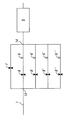
図1を参照にすると、本発明に係るガス入口とインターフェースを取る同位体比光学分光計20が概略的に示される。分光計は、それぞれ、測定セル9からガスを提供するための及び除去するための、ガス入口ライン1ならびにガス出口ライン2を有する。測定セルは、マルチパス光学セルである。同位体比光学分光計は、ガス入口システムとインターフェースを取る同位体比質量分光計と交換され得ることは当業者に明らかになるであろう。同位体比光学分光計は、レーザ分光計、すなわち、マルチパスレーザセルのような測定セルを用いるものであり得る。それゆえ、以下の実施形態に記載されるような本発明のシステム及び方法は、光学分光計を用いて構成され得るが、本発明は、質量分光計または他の分光計を用いる使用に同様に適用可能であることを認識されたい。
Referring to FIG. 1, an isotope ratio
測定予定の分析物ガス(試料ガスまたは基準ガス)が、混合接合部15の方へ分析物ガス入口ライン21を通って、ガス供給部(図示しない)から輸送される。そこから、分析物ガスは、マルチパス測定セル9の中に及びマルチパス測定セル9を通るガス入口ライン1に沿って移動する。ガスの輸送は、例えば膜ポンプであり得る真空ポンプ11によって駆動される。ガス入口ラインにおけるガスは、例えば分析物ガスを希釈するときにまたは測定セルをフラッシュするために、キャリアガス入口ライン22によって、代わりにまたは更に提供され得る。
The analyte gas to be measured (sample gas or reference gas) is transported from the gas supply (not shown) through the analyte
バイパスガスライン3は、第1のバイパス接合部13及び第2のバイパス接合部14でガス入口ライン1に接続される。第1のバイパス接合部に到達した試料ガスは、したがって、ガス入口ラインに沿って、バイパスガスラインに沿って、またはその両方に沿って移動することができる。弁7及び弁8は、それぞれ、バイパスガスライン及びガス入口ラインに沿って、ガス流を制御する。弁7が開かれる(かつ弁8が閉じられる)とき、ガスは、バイパスガスラインのみに沿って及び測定セルの中に流れる。弁7を閉じること及び弁8を開けることは、ガスがガス入口ラインのみを通って及び測定セルの中に流れるように、流れを変える。第1及び第2の接合部間のガス入口ライン上の固定流れ制限部6は、この構成でガス流を低減する。
The bypass gas line 3 is connected to the gas inlet line 1 at the
バイパスラインの中へのガス流のみを制御することが有利であり得る。それゆえ、システムの別の構成は、バイパスラインに沿ってガス流を制御するための弁7を含むが、第1のバイパス接合部と第2のバイパス接合部との間のガス入口ライン上に弁を含まない。この構成では、常に、固定流れ制限部6を通るガス流が存在するが、高いガス流は、ガス流が、ガス流制限部に加えてバイパスを通ることを可能にするように弁7を開くことよって切り換えられ得る。この設定の利点は以下のものである。
・費用及び複雑さ(1つの弁のみ)の低減
・制限部を有するラインが、常にフラッシュされる。さもなければ、これは、メモリー効果の元となり得る
・弁が存在せず、それゆえ、メモリー及び切り換え時間を増加させ得る、低流量ラインにおける潜在的な無駄容積が存在しない
・弁及び潜在的な無駄容積が位置するラインが、高流量によってフラッシュされ、それゆえ、無駄容積はさほど重大でなくなる
It may be advantageous to control only the gas flow into the bypass line. Therefore, another configuration of the system includes a valve 7 for controlling gas flow along the bypass line, but on the gas inlet line between the first bypass junction and the second bypass junction. Does not include valves. In this configuration, there is always a gas flow through the fixed
• Reduction of cost and complexity (only one valve) • Lines with restrictions are always flushed. Otherwise, this can be the source of the memory effect • There is no valve and therefore there is no potential waste volume in the low flow line that can increase memory and switching time • Valve and potential The line where the waste volume is located is flushed by the high flow rate, and therefore the waste volume is less critical
制限部の寸法は、ガス流を決定する。いくつかの実施形態において、制限部が、バイパスラインを通るガス流の1/10であるガス流を提供するように構成される。これは、バイパスガスラインを通る80mL/分のガス流の場合、8mL/分の流れが、ガス入口ライン上の制限部を通って提供されることを意味する。制限部の他の寸法は、所望のガス流を実現することができる。いくつかの実施形態において、バイパスラインと比較して制限部を通る相対的なガス流は、約1/2〜約1/20、約1/5〜約1/15、または約1/8〜約1/12である。一実施形態において、制限部を通る相対的なガス流は、バイパスラインを通るガス流の約1/10である。他の実施形態では、流れ制限部6が、質量流量制御器または比例弁によって提供されてもよい。
The size of the restriction determines the gas flow. In some embodiments, the restriction is configured to provide a gas flow that is 1/10 of the gas flow through the bypass line. This means that for a gas flow of 80 mL / min through the bypass gas line, a flow of 8 mL / min is provided through the restriction on the gas inlet line. Other dimensions of the restriction can achieve the desired gas flow. In some embodiments, the relative gas flow through the restriction relative to the bypass line is about 1/2 to about 1/20, about 1/5 to about 1/15, or about 1/8 to About 1/12. In one embodiment, the relative gas flow through the restriction is about 1/10 of the gas flow through the bypass line. In other embodiments, the
バイパスラインが、流れ制御器、例えば、バイパスガスラインにおいて流れを選択的に制御するための固定流れ制限部または質量流量制御器(図示しない)などを含有することもまた可能である。 It is also possible for the bypass line to contain a flow controller, such as a fixed flow restriction or a mass flow controller (not shown) for selectively controlling flow in the bypass gas line.
ガス入口ラインは、フィルタ(図示しない)、例えば、測定セルの上流に及び第2のバイパス接合部14の下流に配設される水トラップまたは化学的トラップを更に含んでもよい。
The gas inlet line may further include a filter (not shown), for example, a water trap or chemical trap disposed upstream of the measurement cell and downstream of the
バイパスガスラインの中へのガスの流れが、閉じられた弁7によって阻止されるとき、ガスが、測定セルの方へガス入口ラインを通って流れる。この構成では、測定セルの中へのガス流がガス入口ライン上の制限部6によって限定される。
When gas flow into the bypass gas line is blocked by the closed valve 7, gas flows through the gas inlet line towards the measuring cell. In this configuration, the gas flow into the measuring cell is limited by the
典型的な設定では、測定セルの中へのガス流が、大気圧に近い分析物及び/またはキャリアガス入口ラインにおける圧力の場合、80mL/分に設定される。より一般的には、測定セル中のガス流が、送達されたガスの圧力に従って変動する。測定セルの中へのガス流は、弁8を閉じたままにする及び弁7を開いたままにする(または弁8が存在しない実施形態では弁7のみを開いたままにする)ことによって、バイパスガスラインを通して実現され得る。高流量が、測定セルのフラッシング及び/または充填に望ましい可能性がある。測定セルが最初の高流量でフラッシュされた及び/または充填された後、弁7が閉じられると同時に、弁8が開かれる(または弁8が存在しない実施形態では弁7のみが閉じられる)。伝達ガスライン上の制限部6は、測定セルの中への流量を低減する。例えば、制限は、制限部を通る流れが、バイパスを通る流れの1/10であるように構成され得る。結果として、例えば、80mL/分でバイパスを通る測定セルの充填及び/またはフラッシング後、制限部を通るガス流に対する切換部が、8mL/分の低減された流量を導くことになる。
In a typical setting, the gas flow into the measurement cell is set to 80 mL / min for analytes near atmospheric pressure and / or pressure at the carrier gas inlet line. More generally, the gas flow in the measurement cell varies according to the pressure of the delivered gas. The gas flow into the measuring cell is by leaving the valve 8 closed and the valve 7 open (or only the valve 7 open in embodiments where the valve 8 is not present). It can be realized through a bypass gas line. High flow rates may be desirable for flushing and / or filling the measurement cell. After the measuring cell is flushed and / or filled at the first high flow rate, the valve 7 is closed and at the same time the valve 8 is opened (or only the valve 7 is closed in embodiments where the valve 8 is not present). The
一般に、システムを通るガス流は、連続的である。システムを通って流れるガスは、分析物ガス、キャリアガス、または分析物ガスとキャリアガスの混合であり得る。いくつかの構成では、分析物ガスが、キャリアガスで、補充され、すなわち、希釈される。これは、分析物ガスを供給されるとき、システムは、開いた弁12を通って流れるキャリアガスによって希釈され得る開いた弁5を通る分析物ガスの流れを可能にすることを意味する。分析物及びキャリアガスの流れが、混合接合部15で合流し、そこで、2つのガスが、高流量でバイパスラインを経由して、または減少された流量で制限部を通るガス入口ラインを経由して、組み合わさる及び測定セルの中に流れる。弁12が閉じられる場合、分析物ガスのみが、測定セルの中に流れる。
In general, the gas flow through the system is continuous. The gas flowing through the system can be an analyte gas, a carrier gas, or a mixture of an analyte gas and a carrier gas. In some configurations, the analyte gas is replenished, i.e. diluted, with a carrier gas. This means that when supplied with analyte gas, the system allows for the flow of analyte gas through the open valve 5 that can be diluted by the carrier gas flowing through the
ガス入口ラインは、測定予定の試料の全てが、試料ガス供給部から測定セルに伝達されることを確実にする。分光計の中への一定のガス流が、試料ガスの流れをキャリアガスの流れを用いて増大することによって確実にされ得、そのキャリアガスは、好ましくは試料がないガスである。このようにして、試料が無駄にされない。好ましくは、弁5を通る試料ガス流が、測定セルの中への流量よりも少ない。キャリアガスは、この構成において混合接合部の方へ流れることになり、ガスの流れが常に測定セルの方になること確実にする。わずかな試料ガス流が存在するまたは試料ガス流が存在しない、すなわち、試料ガスの濃度がゼロに近い場合、キャリアガスは、ガス流を補給して、測定セルの中への必要なガス流を提供する。測定セルを通るものよりも混合接合部の方への試料の高いガス流が存在する場合には、キャリアガスの中への及びキャリアガス入口ライン上の開口部を通る過剰試料ガスの逆流が存在することがある。本発明のガス入口システムと組み合わされ得るガス入口システムのより詳細な記載が、WO2014/170179に提供される。 The gas inlet line ensures that all of the sample to be measured is transferred from the sample gas supply to the measurement cell. A constant gas flow into the spectrometer can be ensured by increasing the sample gas flow with the carrier gas flow, which is preferably a sample-free gas. In this way, the sample is not wasted. Preferably, the sample gas flow through the valve 5 is less than the flow rate into the measuring cell. The carrier gas will flow towards the mixing junction in this configuration, ensuring that the gas flow is always towards the measuring cell. If there is a small sample gas flow or no sample gas flow, i.e. the concentration of the sample gas is close to zero, the carrier gas will replenish the gas flow and divert the required gas flow into the measurement cell. provide. If there is a higher gas flow of sample towards the mixing junction than through the measurement cell, there is a backflow of excess sample gas into the carrier gas and through the opening on the carrier gas inlet line There are things to do. A more detailed description of a gas inlet system that can be combined with the gas inlet system of the present invention is provided in WO 2014/170179.
分析物ガス及び/またはキャリアガスの流れを更に制御することが望ましい可能性がある。これは、分析物ガス入口ライン上、キャリアガス入口ライン上、またはその両方上に、例えば、質量流量制御器、比例弁、体積流量制御器、または同様のものを含むことによって行われ得る。 It may be desirable to further control the flow of analyte gas and / or carrier gas. This can be done by including, for example, a mass flow controller, a proportional valve, a volume flow controller, or the like, on the analyte gas inlet line, on the carrier gas inlet line, or both.
測定セル中の圧力は、ポンプ速度を制御することによって一定に保たれる。これは、測定セル中の圧力センサ17からの信号を、ポンプ11に接続されると共にポンプ11を調節することができる制御器18に提供することによって行われ得る。ポンプ速度は、セル中の実際の圧力と基準設定の比較に従って、その後に調節される。あるいは、測定セル中の圧力は、測定セルと真空ポンプとの間の調整可能弁の調整によって調整され得る。そのような構成において、弁の位置が、センサからの信号の受信に応答して、制御器によってポンプ速度の代わりに調節される。そのような手段によって、測定セル中の圧力が、典型的には20〜200mbarの範囲にある固定値に維持される。いくつかの実施形態において、圧力は、40〜200mbar、40〜150mbar、または80〜120mbarに維持され得る。いくつかの実施形態において、測定セル中の圧力が、約100mbarに維持され得る。キャリアガスにおける分析物ガス濃度は、切り換え可能な流れ制限部の上流に設定された分析物ガスとキャリアガスとの混合比によって、好ましくは一定に保たれる。
The pressure in the measuring cell is kept constant by controlling the pump speed. This can be done by providing a signal from the pressure sensor 17 in the measurement cell to a
同じ制御器18がまた、弁7及び弁8、ならびに/または弁5及び弁12を制御してもよいし、あるいはそれらは、別個の制御器(図示しない)によって動作されてもよい。
The
測定セルのフラッシングを最適化するために、セルは、充填の前にフラッシュされ得る。例えば、セルは、キャリアガスを使用してフラッシュされ得る。いくつかの実施形態において、セルが、試料がない空気(例えばCO2がない空気など)、または試料がないキャリアガスであり得る、ゼロの空気を使用してフラッシュされ得る。セルのフラッシングのために高流量バイパスガスラインを使用することが好都合であり得る。セルをキャリアガスでフラッシュした後、セルが、試料及び/または基準ガスで充填され得る。この目的のために、キャリアガス入口ライン及び分析物ガス入口ラインを通るガス流を調節する弁5、弁12が、適切なガス流を可能にするように調整され得る。試料がないキャリアガスは、したがって、キャリアガス入口ラインを通してキャリアガスを提供することによって提供され得、その間に、分析物ガスラインを通るガス流が、閉じられた弁5によって阻止される。この構成では、キャリアガスは、バイパスガスラインを通る高流量のために、弁7を開いたままにすることによって、ガス入口ラインの中に及びバイパスライン3を通して、開いた弁12を通って流れる。フラッシング手順の間に、弁8はまた、存在する場合、弁8のガスラインをフラッシュするためにも開かれる必要がある。勿論、このラインのフラッシングはまた、セルのフラッシング前または後に行われ得る。セルのフラッシング後、弁5は、分析物ガスが測定セルの中に流れることを可能にするように開かれ得る。引き続き(例えば、分析物ガスを用いる所望の圧力及び濃度までのセルの充填後)、または同時に、低減された流量で制限部6を通して分析物ガスを送達するように、弁8は開かれ得、弁7は閉じられ得る。分析物ガスはまた、必要な場合、開いた弁12を通して、キャリアガスと混合され得る。
In order to optimize the flushing of the measuring cell, the cell can be flushed before filling. For example, the cell can be flushed using a carrier gas. In some embodiments, the cell can be flushed using zero air, which can be sample free air (eg, air without CO 2 ) or carrier gas without sample. It may be advantageous to use a high flow bypass gas line for cell flushing. After flushing the cell with a carrier gas, the cell can be filled with a sample and / or a reference gas. For this purpose, the
圧力サイクルが、無駄容積の影響を低減するまたは排除するために行われ得る。これは、測定セルをキャリアガスまたは分析物ガスで充填すること、続いて、真空ポンプを使用してセルを排気することによって実現され得る。この構成において、バイパスガスラインは、弁8を閉じたまま及び弁7を開いたままにすることによって、好ましくはセルを充填するために使用される。測定セル中の圧力センサ17からの入力が、弁5及び/または弁12の開閉を調節するために使用され得る。それゆえ、測定セルが排気されると、両方の弁が閉じられ、一方で、弁の一方または両方が、キャリアガスまたは分析物ガスでセルを充填するために開かれ得る。測定セルを充填する及び排気するプロセスは、無駄容積を効果的に取り除くまたは最小限にするために、1回以上繰り返され得る。
A pressure cycle can be performed to reduce or eliminate the effect of dead volume. This can be accomplished by filling the measurement cell with a carrier gas or analyte gas, followed by evacuating the cell using a vacuum pump. In this configuration, the bypass gas line is preferably used to fill the cell by keeping valve 8 closed and valve 7 open. Input from the pressure sensor 17 in the measurement cell can be used to adjust the opening and closing of the valve 5 and / or
別の構成では、測定セルが、高流量バイパスを通る試料で充填する前に排気され得る。一旦測定セルが充填され、かつ基準圧力(例えば、100mbarの圧力)に到達すると、バイパスラインは、閉じられ得、測定セルを通る遅い流れを維持するように開かれた制限部を通って流れ得る。セルの基準圧力は、典型的には、約10〜300秒以内に到達されるが、一般に約5〜600秒以内に到達される流量及び圧力設定に依存し得る。 In another configuration, the measurement cell can be evacuated prior to filling with sample through the high flow bypass. Once the measurement cell is filled and a reference pressure (eg, 100 mbar pressure) is reached, the bypass line can be closed and flow through a restriction that is open to maintain a slow flow through the measurement cell . The reference pressure of the cell is typically reached within about 10-300 seconds, but can generally depend on the flow rate and pressure settings reached within about 5-600 seconds.
測定セルの中への流量の切り換えはまた、ガス濃度に依存して、または圧力及び濃度の組み合わせに依存して行われ得る。例えば、測定セルは、開いたバイパスガスラインを通る試料ガス及び/または基準ガスで充填され得る。測定セル中のガス濃度の決定が、弁7及び8の位置を調節するために制御器に信号を送信するように使用される。それゆえ、測定セルが、開いたバイパスガスラインを通るガスで充填され得る。例えばCO2などの測定予定のガスの濃度が一旦所定の閾値に到達すると、制御器は、弁7を通してバイパスガスラインを閉めるように、かつガス入口ライン上の弁8を開くことによって固定流れ制限部を通して流れを誘導するように信号を送信する。 Switching the flow rate into the measuring cell can also be performed depending on the gas concentration or depending on the combination of pressure and concentration. For example, the measurement cell can be filled with sample gas and / or reference gas through an open bypass gas line. Determination of the gas concentration in the measuring cell is used to send a signal to the controller to adjust the position of valves 7 and 8. Therefore, the measuring cell can be filled with gas through an open bypass gas line. Once the concentration of the gas to be measured, such as CO 2 , reaches a predetermined threshold, the controller will limit the fixed flow by closing the bypass gas line through valve 7 and opening valve 8 on the gas inlet line. Send a signal to guide the flow through the part.
ガス流の類似の調節が、測定セル中の同位体比の決定に基づいて、行われ得る。それゆえ、同位体比の決定に基づいて、弁7及び弁8が、バイパスラインからの及び制限部を通る流れ、またはその逆の流れを切り換えるように調整され得、調整は、ガス流制御器からの信号によって提供される。 A similar adjustment of the gas flow can be made based on the determination of the isotope ratio in the measurement cell. Therefore, based on the determination of the isotope ratio, valve 7 and valve 8 can be adjusted to switch the flow from the bypass line and through the restriction, or vice versa, the adjustment being made to the gas flow controller. Provided by the signal from.
別の構成において、測定セルは、分析のためにガスでの充填の前に排気される。そのような構成において、測定セルは、真空ポンプによって排気され、その間に弁7及び弁8は、測定セルの排気を可能にするために、閉じられたままである。測定セル中の圧力は、圧力センサによって監視され、その圧力センサは、ポンプ速度を調整するための制御器18に信号を送信する。セルが排気された後、それは、バイパスラインを通してガス流を誘導することによって、弁7を開くことによって、または、代わりに、弁8を開くことによって制限部を通してガス流を誘導することによって、分析物ガスで充填され得る。
In another configuration, the measurement cell is evacuated prior to filling with gas for analysis. In such a configuration, the measurement cell is evacuated by a vacuum pump while valve 7 and valve 8 remain closed to allow the measurement cell to be evacuated. The pressure in the measuring cell is monitored by a pressure sensor, which sends a signal to the
いくつかの実施形態において、弁7及び弁8の代わりにガス入口が、ガス入口ラインに沿って(ただしバイパスラインに沿わずに)第1及び第2のバイパス接合部間に、またはバイパスラインに沿って(ただしガス入口ラインに沿わずに)第1及び第2のバイパス接合部間にガス流を誘導するように、第1のバイパス接合部13に位置付けられた単一の三方向弁を有することができる。
In some embodiments, instead of valve 7 and valve 8, a gas inlet is provided along the gas inlet line (but not along the bypass line) between the first and second bypass junctions, or to the bypass line. With a single three-way valve positioned at the
図2には、代替配設が示され、それにおいて2つの弁7及び弁8の代わりに、単一切換弁26が、第1のバイパス接合部13に配設される。切換弁の位置は、それぞれ、バイパスガスライン及び入口ガスラインにおけるガス流を制御する。それゆえ、第1の位置において、切換弁は、ガス入口ラインを通るガス流を阻止するが、バイパスラインを通るガス流を可能にする。この構成は、例えば、測定セルの充填及び/またはフラッシングの間に有用である。第2の位置において、切換弁は、バイパスガスラインを通るガス流を阻止するが、ガス入口ラインを通るガス流を可能にする。この位置において、測定セルの中へのガス流が、流れ制限部6によって調節される。切換弁はまた、1つの位置においてバイパスガスライン及び入口ガスラインの中への同時のガス流を可能にし得る三方向弁として提供され得る。別の位置では、弁は、バイパスラインの中へのガス流を可能にし得、入口ガスラインを通る流れを阻止し、または入口ガスラインを通るガス流を可能にし、かつバイパスラインを通る流れを阻止する。
In FIG. 2, an alternative arrangement is shown, in which a
システムは、並列に配設され得る複数の代替の流れ制限部を含むように配設され得る。図3の実施形態に示されるこの例示において、ガス入口ライン1上に4つの並列制限ラインが示される。4つの制限ラインは、第1のバイパス接合部13で、及び第2のバイパス接合部14で交わる。各制限ライン上に、制限部6、6’、6’’、6’’’が、提供される。各ラインを通るガス流は、弁8、8’、8’’、8’’’によって制御される。これらの弁によって、制限部間で切り換えが行われ得、測定セルの中へのガス流の選択的な制御を可能にする。例えば、1つの位置において、開いた弁8を通して、制限部6を通るガスの流れが存在する。他の制限部6’、6’’、6’’’を通るガス流が、閉じられた弁8’、8’’、8’’によって阻止される。弁8’を閉じると同時に弁8’を開くことによって、制限部6への制限部6’を通る流れからの切り換えが行われ得る。類似の様式で、制限ライン上の弁8、8’、8’’、8’’’を選択的に開く及び/または閉じることによって、制限部の1つ以上を通るガス流が、選択的に制御され得る。4つの制限部は、制限部間の切り換えが、測定セル9の中への流量の変化を結果としてもたらすように、好ましくは異なる。任意の数の制限ラインが、類似の様式で、及び制限部を通るガス流を選択的に制御するために必要に応じて追加の弁で、配設され得る。更に、各制限ライン上に別々の弁を有する代わりに、制限ラインの中への流れを選択的に制御するために、接合部、例えば第1のバイパス接合部に配設された切換弁が存在し得る。制限部を通るガス流の間に、バイパスラインが、バイパスライン上の弁7によってまたは第1のバイパス接合部における切換弁を通して閉じられ得る。
The system can be arranged to include a plurality of alternative flow restrictors that can be arranged in parallel. In this illustration shown in the embodiment of FIG. 3, four parallel limit lines are shown on the gas inlet line 1. The four limit lines intersect at the
特許請求の範囲を含めて、本明細書において使用される際、文脈が別段示さない限り、用語の単数形は複数形も含むものとして、また逆の場合も同様のものとして解釈される。それゆえ、本明細書において使用される際、別段文脈が他に明確に示さない限り、単数形「a」、「an」、及び「the」は、複数の指示内容を含むことに留意されたい。 As used herein, including the claims, the singular forms of the term include the plural and vice versa unless the context indicates otherwise. Therefore, as used herein, the singular forms “a”, “an”, and “the” include plural referents unless the context clearly indicates otherwise. .
記載及び特許請求の範囲全体を通して、用語「備える」、「含む」、「有する」、及び「含有する」、ならびにそれらの変形が、「限定するものではないが、〜を含む」意味として理解されるべきであり、他の構成要素を除外することを意図されない。 Throughout the description and claims, the terms “comprising”, “including”, “having”, and “containing”, and variations thereof, are understood as meaning “including but not limited to”. Should be excluded and is not intended to exclude other components.
依然として本発明の範囲と共にある間に本発明の前述の実施形態への変形が、成され得るが、依然として本発明の範囲内にあることが認識されるであろう。明細書に開示された特徴は、別段述べられない限り、同じ、同等の、または類似の目的にかなう代替の特徴と交換され得る。それゆえ、別段述べられない限り、開示された各特徴は、一般的な一連の同等または類似の特徴の一実施例を表わす。 It will be appreciated that variations to the foregoing embodiments of the invention may be made while still in conjunction with the scope of the invention, but are still within the scope of the invention. Features disclosed in the specification may be interchanged with alternative features serving the same, equivalent, or similar purposes, unless otherwise stated. Thus, unless expressly stated otherwise, each feature disclosed represents one example of a generic series of equivalent or similar features.
例示的な言い回しの使用、例えば、「例えば(for instance)」、「例えば〜など(such as)」、「例えば(for example)」、及び同様のものなどは、単に本発明をより良く例示することを意図され、そのように特許請求されない限り、本発明の範囲の限定を示すものではない。明細書に記載されたあらゆるステップは、文脈が別段明確に示さない限り、任意の順序でまたは同時に行われてもよい。 The use of exemplary language such as “for instance”, “for example, such as“ such as ”,“ for example ”, and the like merely exemplifies the present invention better. It is not intended to be exhaustive or to limit the scope of the invention, unless so claimed. All steps described in the specification may be performed in any order or simultaneously, unless the context clearly indicates otherwise.
明細書に開示された特徴及び/またはステップの全ては、特徴及び/またはステップのうちの少なくともいくつかが相互排他的である組み合わせを除いて、任意の組み合わせで組み合わされ得る。特に、本発明の好適な特徴は、本発明の全ての態様に適用でき、任意の組み合わせで使用されてもよい。 All of the features and / or steps disclosed in the specification may be combined in any combination, except combinations where at least some of the features and / or steps are mutually exclusive. In particular, the preferred features of the invention are applicable to all aspects of the invention and may be used in any combination.
Claims (28)
ガス流をそれぞれ受け取る及び放出するための入口ならびに出口を有する測定セルと、
前記入口に流体接続されたガス入口ラインと、
前記出口に流体接続されたガス出口ラインと、
前記同位体比分析器の中へのガス流を選択的に制御するための、前記ガス入口ライン上の少なくとも1つの切り換え可能な流れ制限部と、を備え、
前記切り換え可能な流れ制限部が、第1のバイパス接合部及び第2のバイパス接合部において前記ガス入口ラインに接続されたバイパスガスラインと、前記第1のバイパス接合部と前記第2のバイパス接合部との間において前記ガス入口ライン上に配設された流れ制限部と、によって提供され、
前記システムが、少なくとも第1及び第2の弁位置を有する、前記バイパスガスライン及び/または前記ガス入口ラインにおけるガス流を制御するための少なくとも1つの弁を更に備え、第1の位置において、ガスが、第1のゼロ以外の流量で、前記バイパスライン及び前記同位体比分析器を通って流れるように誘導され、かつ第2の位置において、ガスが、前記第1のゼロ以外の流量とは異なる第2のゼロ以外の流量で、前記ガス入口ライン上の前記流れ制限部を通って前記同位体比分析器の中に流れるように誘導される、システム。 A system for controlling gas flow in a continuous flow isotope ratio analyzer comprising:
A measuring cell having an inlet and an outlet for receiving and releasing a gas flow, respectively;
A gas inlet line fluidly connected to the inlet;
A gas outlet line fluidly connected to the outlet;
At least one switchable flow restriction on the gas inlet line for selectively controlling gas flow into the isotope ratio analyzer;
The switchable flow restriction includes a bypass gas line connected to the gas inlet line at the first bypass joint and the second bypass joint, the first bypass joint, and the second bypass joint. A flow restricting part disposed on the gas inlet line between the parts,
The system further comprises at least one valve for controlling gas flow in the bypass gas line and / or the gas inlet line having at least first and second valve positions, wherein in the first position a gas Is induced to flow through the bypass line and the isotope ratio analyzer at a first non-zero flow rate, and in a second position, gas is the first non-zero flow rate. The system is guided to flow into the isotope ratio analyzer through the flow restriction on the gas inlet line at a different second non-zero flow rate.
任意選択的に、前記少なくとも1つの弁が、前記ガス入口ライン上に、前記第1のバイパス接合部と前記第2のバイパス接合部との間に配設された弁を更に備え、この弁が、ガスが前記ガス入口ラインに沿って前記第1のバイパス接合部と第2のバイパス接合部との間を流れることができる、第1の位置と、ガスが前記ガス入口ラインに沿って前記第1のバイパス接合部と第2のバイパス接合部との間を流れることを阻止される、第2の位置と、を有する、請求項4に記載のシステム。 The at least one valve comprises a valve disposed between the first bypass junction and the second bypass junction along the bypass gas line, the gas being the bypass gas A first position capable of flowing between the first bypass junction and the second bypass junction along a line; and a gas bypassing the first bypass junction along the bypass gas line. Having a second position that is prevented from flowing between the second bypass junction;
Optionally, the at least one valve further comprises a valve disposed on the gas inlet line between the first bypass junction and the second bypass junction. A gas is allowed to flow between the first bypass junction and the second bypass junction along the gas inlet line; a first position; 5. The system of claim 4, having a second location that is prevented from flowing between one bypass junction and a second bypass junction.
第1の流量で同位体比決定のために分析物ガスを含むガス流を測定セルの中に提供するステップと、
第2の流量を実現するように、前記測定セルの中への前記ガス流を低減するステップと、
前記分析物中の前記同位体比を決定するステップと、を含み、
前記第1の流量と前記第2の流量との比が、2:1〜20:1の範囲にある、方法。 A method for determining an isotope ratio of an analyte gas in a continuous flow isotope ratio spectrometer comprising:
Providing a gas stream comprising an analyte gas in the measurement cell for isotope ratio determination at a first flow rate;
Reducing the gas flow into the measurement cell to achieve a second flow rate;
Determining the isotope ratio in the analyte, and
The method wherein the ratio of the first flow rate to the second flow rate is in the range of 2: 1 to 20: 1.
第1のゼロ以外の流量で同位体比決定のために分析物ガスを含むガス流を測定セルの中に提供するステップと、
前記第1の流量よりも少ない第2のゼロ以外の流量を実現するように、前記測定セルの中への前記ガス流を低減するステップと、
前記測定セルの中への前記ガス流が前記第2の流量にあるときに前記分析物ガスを測定することによって、前記分析物中の前記同位体比を決定するステップと、を含む、方法。 A method for determining an isotope ratio of an analyte gas in a continuous flow isotope ratio spectrometer comprising:
Providing a gas stream comprising an analyte gas in a measurement cell for isotope ratio determination at a first non-zero flow rate;
Reducing the gas flow into the measurement cell to achieve a second non-zero flow rate that is less than the first flow rate;
Determining the isotope ratio in the analyte by measuring the analyte gas when the gas flow into the measurement cell is at the second flow rate.
Applications Claiming Priority (2)
| Application Number | Priority Date | Filing Date | Title |
|---|---|---|---|
| GB1507440.4A GB2537914B (en) | 2015-04-30 | 2015-04-30 | Flow reduction system for isotope ratio measurements |
| GB1507440.4 | 2015-04-30 |
Publications (2)
| Publication Number | Publication Date |
|---|---|
| JP2016212101A true JP2016212101A (en) | 2016-12-15 |
| JP6282304B2 JP6282304B2 (en) | 2018-02-21 |
Family
ID=53488964
Family Applications (1)
| Application Number | Title | Priority Date | Filing Date |
|---|---|---|---|
| JP2016090330A Active JP6282304B2 (en) | 2015-04-30 | 2016-04-28 | Flow reduction system for isotope ratio measurement |
Country Status (5)
| Country | Link |
|---|---|
| US (1) | US9829431B2 (en) |
| EP (1) | EP3088889B1 (en) |
| JP (1) | JP6282304B2 (en) |
| CN (1) | CN106092907B (en) |
| GB (1) | GB2537914B (en) |
Families Citing this family (11)
| Publication number | Priority date | Publication date | Assignee | Title |
|---|---|---|---|---|
| GB201509412D0 (en) * | 2015-06-01 | 2015-07-15 | Micromass Ltd | Coupling intermediate pressure regions |
| US10241024B1 (en) * | 2016-05-02 | 2019-03-26 | Rashid Mavliev | System and method for characterization of inclusions in liquid samples |
| GB2557670B (en) | 2016-12-15 | 2020-04-15 | Thermo Fisher Scient Bremen Gmbh | Improved gas flow control |
| CN106841459A (en) * | 2017-03-31 | 2017-06-13 | 北京雪迪龙科技股份有限公司 | A kind of gas chromatography combined with mass spectrometry interface, system and flow matches method |
| JP6505166B2 (en) * | 2017-07-21 | 2019-04-24 | 株式会社日立ハイテクサイエンス | Evolved gas analyzer and evolved gas analysis method |
| CN109459396B (en) * | 2018-12-04 | 2023-08-25 | 南京信息工程大学 | Online laser detection analyzer for carbon isotopes of atmospheric particulates and application method thereof |
| GB201903473D0 (en) * | 2019-03-14 | 2019-05-01 | Sumitomo Chemical Co | Interferent and baseline drift correcting gas sensor system |
| CN111707423B (en) * | 2020-06-18 | 2022-04-15 | 苏州镓港半导体有限公司 | Vacuum system leak detection method and leak detection device for vacuum system |
| CN112730781A (en) * | 2020-12-24 | 2021-04-30 | 北京林业大学 | System for continuously measuring stable water isotope value of forest ecological system in situ |
| KR20220159597A (en) * | 2021-05-26 | 2022-12-05 | 세메스 주식회사 | Wafer inspecting apparatus and wafer inspecting method |
| FR3139907A1 (en) * | 2022-09-16 | 2024-03-22 | Centre National De La Recherche Scientifique | Device for coupling an elemental analyzer and an isotope analyzer by laser absorption spectroscopy |
Citations (6)
| Publication number | Priority date | Publication date | Assignee | Title |
|---|---|---|---|---|
| JPS6073336A (en) * | 1983-09-30 | 1985-04-25 | Hitachi Ltd | Sampling gas introducing apparatus |
| JPH04109542A (en) * | 1990-08-29 | 1992-04-10 | Yokogawa Electric Corp | High frequency induction coupled plasma mass spectrometer |
| JPH11337525A (en) * | 1998-05-28 | 1999-12-10 | Aloka Co Ltd | Gas analysis system |
| JP2009531677A (en) * | 2006-03-31 | 2009-09-03 | サーモ・フィッシャー・サイエンティフィク・(ブレーメン)・ゲゼルシャフト・ミト・ベシュレンクテル・ハフツング | Method and apparatus for analyzing isotope ratio |
| CN102928554A (en) * | 2012-09-06 | 2013-02-13 | 中国石油化工股份有限公司 | On-line logging method for methane carbon isotopes |
| WO2014170179A1 (en) * | 2013-04-15 | 2014-10-23 | Thermo Fisher Scientific (Bremen) Gmbh | Gas inlet system for isotope ratio analyser and method of determining an isotope ratio |
Family Cites Families (13)
| Publication number | Priority date | Publication date | Assignee | Title |
|---|---|---|---|---|
| WO2005113830A2 (en) | 2004-05-20 | 2005-12-01 | Waters Investments Limited | System and method for grouping precursor and fragment ions using selected ion chromatograms |
| US7498568B2 (en) | 2005-04-29 | 2009-03-03 | Agilent Technologies, Inc. | Real-time analysis of mass spectrometry data for identifying peptidic data of interest |
| FR2885693B1 (en) * | 2005-05-10 | 2007-09-07 | Sidel Sas | METHOD FOR MEASURING GAS PERMEABILITY WITH QUICK CONDITIONING AND INSTALLATION FOR IMPLEMENTING THE SAME |
| US7928369B2 (en) * | 2006-03-31 | 2011-04-19 | Thermo Fisher Scientific (Bremen) Gmbh | Device for the analysis of isotope ratios |
| US9063162B2 (en) | 2006-05-26 | 2015-06-23 | Waters Technologies Corporation | Apparatus and method for performing mass spectroscopy |
| FR2904689B1 (en) * | 2006-08-01 | 2009-01-16 | Alcatel Sa | GAS SENSOR |
| CN101140252B (en) * | 2006-09-06 | 2011-10-12 | 中国科学院半导体研究所 | System for testing gas sensors or semiconductor device performance |
| DE102007031680A1 (en) * | 2007-07-06 | 2009-01-08 | Thermo Fisher Scientific (Bremen) Gmbh | Apparatus for providing gases, in particular for the isotope ratio analysis |
| US7810376B2 (en) * | 2007-11-06 | 2010-10-12 | Picarro, Inc. | Mitigation of gas memory effects in gas analysis |
| WO2009146345A1 (en) | 2008-05-29 | 2009-12-03 | Waters Technologies Corporation | Techniques for performing retention-time matching of precursor and product ions and for constructing precursor and product ion spectra |
| US20110201126A1 (en) * | 2010-02-17 | 2011-08-18 | Graham John Hughes | Interface to a mass spectrometer |
| RU2595509C2 (en) | 2011-09-27 | 2016-08-27 | Амазон Текнолоджис, Инк. | Organisation of browsing session history |
| CN104838468B (en) | 2012-12-20 | 2017-03-08 | Dh科技发展私人贸易有限公司 | For quantitative scheduled MS3 |
-
2015
- 2015-04-30 GB GB1507440.4A patent/GB2537914B/en active Active
-
2016
- 2016-04-20 EP EP16166279.6A patent/EP3088889B1/en active Active
- 2016-04-28 JP JP2016090330A patent/JP6282304B2/en active Active
- 2016-04-29 CN CN201610279169.4A patent/CN106092907B/en active Active
- 2016-04-29 US US15/142,329 patent/US9829431B2/en active Active
Patent Citations (6)
| Publication number | Priority date | Publication date | Assignee | Title |
|---|---|---|---|---|
| JPS6073336A (en) * | 1983-09-30 | 1985-04-25 | Hitachi Ltd | Sampling gas introducing apparatus |
| JPH04109542A (en) * | 1990-08-29 | 1992-04-10 | Yokogawa Electric Corp | High frequency induction coupled plasma mass spectrometer |
| JPH11337525A (en) * | 1998-05-28 | 1999-12-10 | Aloka Co Ltd | Gas analysis system |
| JP2009531677A (en) * | 2006-03-31 | 2009-09-03 | サーモ・フィッシャー・サイエンティフィク・(ブレーメン)・ゲゼルシャフト・ミト・ベシュレンクテル・ハフツング | Method and apparatus for analyzing isotope ratio |
| CN102928554A (en) * | 2012-09-06 | 2013-02-13 | 中国石油化工股份有限公司 | On-line logging method for methane carbon isotopes |
| WO2014170179A1 (en) * | 2013-04-15 | 2014-10-23 | Thermo Fisher Scientific (Bremen) Gmbh | Gas inlet system for isotope ratio analyser and method of determining an isotope ratio |
Non-Patent Citations (1)
| Title |
|---|
| PROSSER, S. J. 外3名: "Rapid, Automated Analysis of 13C and 18O of CO2 in Gas Samples by Continuous-flow, Isotope Ratio Mas", BIOLOGICAL MASS SPECTROMETRY, vol. 20, no. 11, JPN6017016115, 1991, pages 724 - 730, XP055117282, DOI: doi:10.1002/bms.1200201112 * |
Also Published As
| Publication number | Publication date |
|---|---|
| GB2537914A (en) | 2016-11-02 |
| EP3088889A1 (en) | 2016-11-02 |
| CN106092907A (en) | 2016-11-09 |
| GB201507440D0 (en) | 2015-06-17 |
| US9829431B2 (en) | 2017-11-28 |
| JP6282304B2 (en) | 2018-02-21 |
| US20160320294A1 (en) | 2016-11-03 |
| CN106092907B (en) | 2020-04-17 |
| GB2537914B (en) | 2019-03-20 |
| EP3088889B1 (en) | 2020-09-23 |
Similar Documents
| Publication | Publication Date | Title |
|---|---|---|
| JP6282304B2 (en) | Flow reduction system for isotope ratio measurement | |
| JP6461254B2 (en) | Gas injection system for isotope ratio analyzer and method for determining isotope ratio | |
| US10388498B2 (en) | Gas flow control | |
| US10338044B2 (en) | Method and apparatus for reducing gas consumption in continuous flow analytical instruments | |
| CN106093251B (en) | Method and apparatus for pre-concentration gaseous sample | |
| JP6290315B2 (en) | Gas flow control | |
| GB2513119A (en) | Gas inlet system for isotope ratio analyser | |
| GB2513120A (en) | Method of determining an isotope ratio | |
| JP2001221720A (en) | Method and apparatus for calibrating gas analyzer | |
| JP2023144425A (en) | Gas analyzer and calibration gas supply method | |
| JP2015148459A (en) | Gas analysis device | |
| GB2513118A (en) | Gas inlet system for isotope ratio analyser | |
| JP2007248122A (en) | Analyzer |
Legal Events
| Date | Code | Title | Description |
|---|---|---|---|
| RD04 | Notification of resignation of power of attorney |
Free format text: JAPANESE INTERMEDIATE CODE: A7424 Effective date: 20170425 |
|
| A131 | Notification of reasons for refusal |
Free format text: JAPANESE INTERMEDIATE CODE: A131 Effective date: 20170515 |
|
| A521 | Request for written amendment filed |
Free format text: JAPANESE INTERMEDIATE CODE: A523 Effective date: 20170815 |
|
| TRDD | Decision of grant or rejection written | ||
| A01 | Written decision to grant a patent or to grant a registration (utility model) |
Free format text: JAPANESE INTERMEDIATE CODE: A01 Effective date: 20171225 |
|
| A61 | First payment of annual fees (during grant procedure) |
Free format text: JAPANESE INTERMEDIATE CODE: A61 Effective date: 20180123 |
|
| R150 | Certificate of patent or registration of utility model |
Ref document number: 6282304 Country of ref document: JP Free format text: JAPANESE INTERMEDIATE CODE: R150 |
|
| R250 | Receipt of annual fees |
Free format text: JAPANESE INTERMEDIATE CODE: R250 |
|
| R250 | Receipt of annual fees |
Free format text: JAPANESE INTERMEDIATE CODE: R250 |
|
| R250 | Receipt of annual fees |
Free format text: JAPANESE INTERMEDIATE CODE: R250 |
|
| R250 | Receipt of annual fees |
Free format text: JAPANESE INTERMEDIATE CODE: R250 |