JP2016207251A - Female terminal structure - Google Patents

Female terminal structure Download PDF

Info

Publication number
JP2016207251A
JP2016207251A JP2015082906A JP2015082906A JP2016207251A JP 2016207251 A JP2016207251 A JP 2016207251A JP 2015082906 A JP2015082906 A JP 2015082906A JP 2015082906 A JP2015082906 A JP 2015082906A JP 2016207251 A JP2016207251 A JP 2016207251A
Authority
JP
Japan
Prior art keywords
female terminal
terminal
wall
hole
receiving hole
Prior art date
Legal status (The legal status is an assumption and is not a legal conclusion. Google has not performed a legal analysis and makes no representation as to the accuracy of the status listed.)
Abandoned
Application number
JP2015082906A
Other languages
Japanese (ja)
Inventor
雅和 長岡
Masakazu Nagaoka
雅和 長岡
Current Assignee (The listed assignees may be inaccurate. Google has not performed a legal analysis and makes no representation or warranty as to the accuracy of the list.)
Yazaki Corp
Original Assignee
Yazaki Corp
Priority date (The priority date is an assumption and is not a legal conclusion. Google has not performed a legal analysis and makes no representation as to the accuracy of the date listed.)
Filing date
Publication date
Application filed by Yazaki Corp filed Critical Yazaki Corp
Priority to JP2015082906A priority Critical patent/JP2016207251A/en
Publication of JP2016207251A publication Critical patent/JP2016207251A/en
Abandoned legal-status Critical Current

Links

Images

Abstract

PROBLEM TO BE SOLVED: To provide a female terminal structure capable of effectively absorbing vibrations and suppressing increase in the number of components by elastically holding the female terminal against a terminal housing hole by using spring reaction of a stabilizer having the female terminal.SOLUTION: A female terminal 1 is inserted into the inside from an end opening 3a of a terminal housing hole 3 formed on a connector housing 2, which causes a front end hole edge 18a of a lance hole 18 to be latched to a lance part 4 formed on an upper wall of the terminal housing hole. The female terminal has a pair of stabilizers 20 extending to a vertical direction from an upper end edge of both side wall parts 14, cutting parts 21, 22 cut toward both side-wall parts side from both side edges of a stationary side base part 20a of the stabilizer are formed thereon, and the stabilizer is configured as a spring member which can elastically come into contact with a projection 8 formed on an inside surface 3f of the terminal housing hole, by the cutting parts.SELECTED DRAWING: Figure 4

Description

本発明は、例えば自動車内に配設されたワイヤーハーネスなどの接続に用いられるコネクタに電気的に接続される雌端子構造に関する。   The present invention relates to a female terminal structure that is electrically connected to a connector used for connecting, for example, a wire harness disposed in an automobile.

従来のコネクタに電気的に接続される雌端子構造としては、以下の特許文献1に記載されているものが知られている。   As a female terminal structure electrically connected to a conventional connector, one described in Patent Document 1 below is known.

概略を説明すれば、前記コネクタは、ボックス状のコネクタハウジングの内部に複数の端子収容孔が貫通形成されていると共に、前記各端子収容孔のそれぞれの内部の軸方向の所定位置に、内外へ弾性変形可能なランス部が設けられている。   In brief, the connector has a plurality of terminal receiving holes formed through a box-shaped connector housing, and the inside and the outside of each terminal receiving hole at a predetermined position in the axial direction. An elastically deformable lance portion is provided.

前記雌端子は、金属板材をプレス成形によって折曲形成されており、ほぼ箱型に形成された端子本体と、該端子本体の長手方向の一端部に一体に結合されて、電線の端末に圧着接続可能なバレル部と、を備えている。   The female terminal is formed by bending a metal plate material by press molding, and is joined integrally to a terminal body formed in a box shape and one end in the longitudinal direction of the terminal body, and is crimped to the end of the electric wire. And a connectable barrel portion.

前記端子本体は、前後に延出した底壁部と、一対の両側壁部と、上壁部とを備えており、前記底壁部の前部における幅方向のほぼ中央には、前記ランス部に係止可能な係止孔が形成されている。   The terminal body includes a bottom wall portion extending in the front-rear direction, a pair of both side wall portions, and an upper wall portion, and the lance portion is provided at a substantially center in the width direction at the front portion of the bottom wall portion. A locking hole that can be locked to is formed.

また、雌端子は、前端側に雄端子を挿入する開口部が形成されていると共に、内部には前記雄端子の先端部が電気的に接触する電気的接触部が設けられている。この電気的接触部は、前記雄端子の先端部を弾性的に接触させるばね片が設けられていると共に、雄端子の先端部が保持される振動規制部を有している。   The female terminal has an opening for inserting the male terminal on the front end side, and an electrical contact portion in which the front end of the male terminal is in electrical contact. The electrical contact portion is provided with a spring piece that elastically contacts the distal end portion of the male terminal, and has a vibration restricting portion that holds the distal end portion of the male terminal.

この振動規制部は、ほぼコ字形状に折曲形成されて、前記本体の内側面に固定されていると共に、前記雄端子が挿入方向に対して振動すると、雄端子の先端部が当接することによって振動を規制するようになっている。   The vibration restricting portion is bent in a substantially U-shape and fixed to the inner surface of the main body. When the male terminal vibrates in the insertion direction, the tip of the male terminal comes into contact. The vibration is regulated by.

特開2005−251741号公報JP 2005-251741 A

しかしながら、前記従来の雌端子構造は、前記雄端子に挿入方向へ振動が発生した際に、前記振動規制部によって挿入方向への振動を規制するだけであるから、例えば挿入方向に対して軸直角方向の振動については規制することができない。この結果、車両の振動や雰囲気温度の変化などの外的要因で生じる端子の微振動による接触位置のずれに起因した劣化を十分に抑制することができない。   However, the conventional female terminal structure only restricts vibration in the insertion direction by the vibration restricting portion when vibration occurs in the insertion direction in the male terminal. Directional vibrations cannot be regulated. As a result, it is not possible to sufficiently suppress the deterioration caused by the displacement of the contact position due to the minute vibration of the terminal caused by external factors such as vehicle vibration and change in ambient temperature.

しかも、前記振動規制部を、雌端子の端子本体とは別体に形成して、端子本体の内側面に固定しなければならないことから、部品点数の増加や製造作業能率の低下を招くおそれがある。   In addition, since the vibration restricting portion must be formed separately from the terminal body of the female terminal and fixed to the inner surface of the terminal body, there is a risk of increasing the number of parts and reducing the manufacturing work efficiency. is there.

本発明は、前記従来の技術的課題に鑑みて案出されたもので、コネクタハウジングの端子収容孔に対して雌端子をばね部材のばね反力を利用して弾性的に保持することにより、振動を効果的に吸収すると共に、部品点数の増加を抑制し得る雌端子構造を提供することを目的としている。   The present invention has been devised in view of the above-described conventional technical problems, and by elastically holding the female terminal with respect to the terminal accommodating hole of the connector housing using the spring reaction force of the spring member, An object of the present invention is to provide a female terminal structure capable of effectively absorbing vibration and suppressing an increase in the number of parts.

請求項1に記載の発明は、コネクタハウジングに形成された端子収容孔に長手方向の一端開口から挿入されて、前記端子収容孔の内壁に形成された係止部に係止して接続されると共に、前端側から内部に挿入された雄端子が弾性的に接触する接点を内部に有する雌端子構造において、前記雌端子の外壁の所定位置に、前記外壁の一部を切り込んで形成され、前記端子収容孔の内壁面に弾接するばね部材を設けたことを特徴としている。   The invention according to claim 1 is inserted into the terminal receiving hole formed in the connector housing from one end opening in the longitudinal direction, and is locked and connected to the locking portion formed in the inner wall of the terminal receiving hole. In addition, in the female terminal structure having a contact inside which the male terminal inserted from the front end side contacts elastically, a part of the outer wall is cut into a predetermined position of the outer wall of the female terminal, A spring member that elastically contacts the inner wall surface of the terminal accommodating hole is provided.

請求項2に記載の発明は、前記雌端子は、前記外壁を構成する両側壁の外端縁から軸直角方向へ延出したスタビライザを有し、該スタビライザの固定側基部の両側縁から前記両側壁側へ向かって切り込まれた切り込み部を形成すると共に、該切り込み部によって前記スタビライザを、前記端子収容孔の内側面に弾接可能な前記ばね部材として構成したことを特徴としている。   According to a second aspect of the present invention, the female terminal has a stabilizer extending in a direction perpendicular to the axis from the outer edge of both side walls constituting the outer wall, and the both side from the both side edges of the fixed side base of the stabilizer. While forming the notch part cut | disconnected toward the wall side, the said stabilizer was comprised as the said spring member which can be elastically contacted to the inner surface of the said terminal accommodation hole by this notch part.

請求項1に記載の発明によれば、雌端子の振動を効果的に抑制できると共に、部品点数の増加を抑制することができる。   According to the first aspect of the present invention, the vibration of the female terminal can be effectively suppressed and the increase in the number of parts can be suppressed.

本発明の第1実施形態に供されるコネクタハウジングの一つの端子収容孔を示す縦断面図である。It is a longitudinal cross-sectional view which shows one terminal accommodation hole of the connector housing provided to 1st Embodiment of this invention. 本実施形態に供される雌端子を示す斜視図である。It is a perspective view which shows the female terminal provided for this embodiment. 本実施形態における端子収容孔に雌端子が挿通される途中の状態を示す要部縦断面図である。It is a principal part longitudinal cross-sectional view which shows the state in the middle of the female terminal being penetrated by the terminal accommodation hole in this embodiment. 本実施形態における端子収容孔に雌端子が最大に挿通された状態を示す要部縦断面図である。It is a principal part longitudinal cross-sectional view which shows the state by which the female terminal was penetrated to the terminal accommodation hole in this embodiment at the maximum. 同じく端子収容孔に雌端子が挿通されて、ランス部がランス孔に係止した状態を断面して示す斜視図である。Similarly, it is a perspective view showing a state where a female terminal is inserted into the terminal receiving hole and the lance portion is locked in the lance hole. 本実施形態に供される雌端子の両スタビライザが端子収容孔の突起部に弾接した状態を示す横断面図である。It is a cross-sectional view which shows the state which both stabilizers of the female terminal provided for this embodiment elastically contacted the projection part of the terminal accommodating hole. 雌端子に雄端子の先端部が挿入されて電気的に接触した状態を断面して示す要部拡大図である。It is a principal part enlarged view which shows the state which the front-end | tip part of the male terminal was inserted in the female terminal, and was contacting electrically. 第2実施形態に供される雌端子を示す斜視図である。It is a perspective view which shows the female terminal provided to 2nd Embodiment. 同雌端子が端子収容孔内に挿通されて、ランス部がランス孔に係止した状態を示す縦断面図である。It is a longitudinal cross-sectional view which shows the state which the same female terminal was penetrated in the terminal accommodation hole, and the lance part latched in the lance hole.

以下、本発明に係る雌端子構造の実施形態を図面に基づいて説明する。この実施形態は、自動車の電気機器類に接続されるワイヤーハーネスを接続するためのコネクタに保持される雌端子1に適用したものである。
〔第1実施形態〕
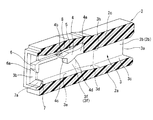
具体的に説明すれば、コネクタは、図1に示すように、内部に複数の端子収容孔(キャビティ)3を有するボックス状の合成樹脂材からなるコネクタハウジング2を備えている。該コネクタハウジング2に有する前記複数の端子収容孔3のうち単一の端子収容孔3を構成する各部位は、平坦状の底壁2aと、該底壁2aの両側縁から一体に立ち上がった両側壁2b、2bと、該両側壁2b、2bの上端縁に一体に設けられた比較的肉厚な上壁2cと、から主として構成されている。
Hereinafter, an embodiment of a female terminal structure according to the present invention will be described with reference to the drawings. This embodiment is applied to the female terminal 1 held by a connector for connecting a wire harness connected to an electric device of an automobile.
[First Embodiment]
More specifically, as shown in FIG. 1, the connector includes a connector housing 2 made of a box-shaped synthetic resin material having a plurality of terminal receiving holes (cavities) 3 therein. Of the plurality of terminal receiving holes 3 in the connector housing 2, each part constituting the single terminal receiving hole 3 has a flat bottom wall 2a and both sides rising integrally from both side edges of the bottom wall 2a. It is mainly composed of walls 2b and 2b and a relatively thick upper wall 2c provided integrally with the upper end edges of the side walls 2b and 2b.

前記各端子収容孔3は、それぞれ横断面ほぼ正方形状に形成されて、図1に示すように、後端側の一端開口3aから前端側の他端開口3bまで貫通形成されていると共に、一端開口3a側の前記底壁2a上面の一部が長手方向(軸方向)に沿って内部所定位置まで水平に切り欠かれて、この切欠面3cによって一端開口3a側の開口面積が大きく形成されている。また、前記切欠面3cの先端縁から他端開口3b方向の所定部位まで立ち上がりテーパ面3dに形成されていると共に、このテーパ面3dから先が平坦面3eに形成されている
また、端子収容孔3の前記上壁2c下面の長手方向ほぼ中央位置には、係止部であるランス部4が一体に形成されている。
Each of the terminal receiving holes 3 is formed in a substantially square cross section, and as shown in FIG. 1, is penetrated from one end opening 3a on the rear end side to the other end opening 3b on the front end side. A part of the upper surface of the bottom wall 2a on the side of the opening 3a is notched horizontally along the longitudinal direction (axial direction) to a predetermined internal position, and the notch surface 3c forms a large opening area on the one end opening 3a side. Yes. Further, the tapered surface 3d is formed from the leading edge of the notch surface 3c to a predetermined portion in the direction of the other end opening 3b, and the tip of the tapered surface 3d is formed on the flat surface 3e. A lance portion 4 as a locking portion is integrally formed at a substantially central position in the longitudinal direction of the lower surface of the upper wall 2c.

この各ランス部4は、コネクタハウジング2を樹脂成形する際に一体に形成されたもので、図1及び図5に示すように、前記上壁2cの下面巾方向のほぼ中央に配置されて、上壁2cの下面に形成された空間部5を介して前記他端開口3b方向へ下り傾斜状に切り起こされた形になっていると共に、前記空間部5を介して上下方向へ弾性変形可能に形成されている。つまり、各ランス部4は、固定側の基端部4aが前記上壁2c下面の巾方向及び長手方向のほぼ中央位置に結合されて、先端部4bが前記基端部4aから前記他端開口3bに向かって下り傾斜状に形成されていると共に、この先端部4b側が基端部4aを支点として前記空間部5を介して上下方向へ弾性変形するようになっている。なお、前記ランス部4の先端部4b全体が下り傾斜状に形成されていることから、前記基端部4aから先端部4bまでの下面4dが下り傾斜状になっている。   Each lance portion 4 is formed integrally when the connector housing 2 is resin-molded. As shown in FIGS. 1 and 5, each lance portion 4 is disposed at a substantially center in the bottom surface width direction of the upper wall 2c. It is cut and raised in a downwardly inclined manner toward the other end opening 3b through a space 5 formed on the lower surface of the upper wall 2c, and can be elastically deformed in the vertical direction via the space 5. Is formed. That is, each lance portion 4 has a base end portion 4a on the fixed side coupled to a substantially central position in the width direction and the longitudinal direction of the lower surface of the upper wall 2c, and the tip end portion 4b opens from the base end portion 4a to the other end opening. The tip 4b side is elastically deformed in the vertical direction via the space 5 with the base end 4a as a fulcrum while being formed in a downwardly inclined shape toward 3b. In addition, since the whole front-end | tip part 4b of the said lance part 4 is formed in the downward inclination, the lower surface 4d from the said base end part 4a to the front-end | tip part 4b is downward inclination.

前記先端部4bは、先端縁が図中ほぼ逆L字形状に切り欠かれた段差状に形成されて、この段差状の係止溝4cが後述するランス孔18の前端孔縁18aに係止されるようになっている。   The tip portion 4b is formed in a stepped shape having a tip edge cut out in a substantially inverted L shape in the drawing, and the stepped locking groove 4c is locked to a front end hole edge 18a of a lance hole 18 described later. It has come to be.

前記係止溝4cは、水平状の上面と該上面の内端縁から上下方向へほぼ垂直に下がった下がり面とからなり、前記上面と下がり面によってほぼL字形状に形成されている。   The locking groove 4c is composed of a horizontal upper surface and a lower surface that descends substantially vertically from the inner edge of the upper surface, and is formed in an approximately L shape by the upper surface and the lower surface.

また、前記端子収容孔3の他端開口3bは、底壁2aと上壁2cの各先端側に一体に形成された上下方向から対向するそれぞれが横断面ほぼ三角状の各凸部6、7によって開口面積が小さく形成されており、この各凸部6,7は先端面が内方へ傾斜状に形成されたテーパ面6a、7aによって後述する雄端子16の先端部を案内するようになっている。   Further, the other end opening 3b of the terminal receiving hole 3 has convex portions 6 and 7 which are integrally formed on the respective distal end sides of the bottom wall 2a and the upper wall 2c and which face each other from the vertical direction and have a substantially triangular cross section. The projecting portions 6 and 7 guide the distal end portion of the male terminal 16 to be described later by tapered surfaces 6a and 7a formed so that the distal end surfaces are inclined inward. ing.

さらに、前記両側壁2b、2bによって形成された端子収容孔3の対向内側面3f、3fには、一対の突起部8,8が一体に設けられている。   Further, a pair of projecting portions 8 and 8 are integrally provided on opposing inner side surfaces 3f and 3f of the terminal accommodating hole 3 formed by the both side walls 2b and 2b.

この各突起部8,8は、図1及び図4に示すように、前記対向する内側面3f、3fの前記ランス部4の両側に位置する部位に設けられて、前記雌端子1が端子収容孔3内に挿入された際に、後述するスタビライザ20,20の先端部20b、20bの外側面が弾接する位置に配置されている。   As shown in FIGS. 1 and 4, the protrusions 8 and 8 are provided at portions of the opposed inner side surfaces 3 f and 3 f located on both sides of the lance portion 4, so that the female terminal 1 accommodates a terminal. When inserted into the hole 3, the outer surfaces of the tip portions 20b, 20b of the stabilizers 20, 20, which will be described later, are arranged at positions where they come into elastic contact.

また、各突起部8,8は、両側面2d、2dの長手方向に沿って細長く形成されていると共に、横断面ほぼ半円形状に形成され、一端開口3a側の一端部外面に細長いテーパ状の案内面8a、8aが形成されている一方、他端部上面に先細り状のテーパ面8b、8bが形成されている。   Each of the protrusions 8 and 8 is elongated along the longitudinal direction of both side surfaces 2d and 2d, is formed in a substantially semicircular cross section, and is elongated and tapered on the outer surface of one end on the one end opening 3a side. The guide surfaces 8a and 8a are formed, and tapered surfaces 8b and 8b are formed on the upper surface of the other end portion.

この各突起部8,8は、コネクタハウジング2を樹脂成形する際に、該コネクタハウジング2と一緒に成形されるようになっている。   The protrusions 8 and 8 are formed together with the connector housing 2 when the connector housing 2 is resin-molded.

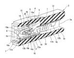
一方、前記雌端子1は、図2〜図5に示すように、導電材である銅や銅合金などの金属プレートをプレス成形によって筒状に折り曲げられて一体に形成されており、ほぼ箱型に形成された先端側の端子本体10と、該端子本体10の後端側に接続部11を介して一体に結合されて電線の端末に圧着して接続するバレル部12と、から構成されている。   On the other hand, as shown in FIGS. 2 to 5, the female terminal 1 is integrally formed by bending a metal plate such as copper or a copper alloy, which is a conductive material, into a cylindrical shape by press molding. A terminal body 10 on the front end side formed on the barrel, and a barrel portion 12 that is integrally coupled to the rear end side of the terminal body 10 via a connection portion 11 and is crimped and connected to the end of the electric wire. Yes.

前記端子本体10は、前後方向に長い角筒状に形成されており、先端部側が二重に重ね合わされた外側(下側)の底壁部13a及び内側(上側)の底壁部13bと、該両底壁部13a、13bの両側縁からほぼ垂直に立ち上げられた一対の側壁部14,14と、該両側壁部14,14の上端縁に設けられた上壁部15と、を備え、これらの各壁部13〜15全体が外壁を構成している。   The terminal body 10 is formed in a rectangular tube shape that is long in the front-rear direction, and has an outer (lower) bottom wall portion 13a and an inner (upper) bottom wall portion 13b in which the tip side is doubled, A pair of side wall portions 14, 14 raised substantially vertically from both side edges of the bottom wall portions 13 a, 13 b, and an upper wall portion 15 provided at the upper edge of the both side wall portions 14, 14. Each of these wall portions 13 to 15 constitutes an outer wall.

また、端子本体10は、各壁部13〜15で隔成された先端部に、後述する雄端子16が挿通する開口部10aが形成されている。   In addition, the terminal body 10 has an opening 10a through which a male terminal 16 (described later) is inserted at a distal end portion separated by the wall portions 13-15.

前記内側の底壁部13bは、前記開口部10aから内部に挿入される雄端子16の先端部が接触する2つの接触ビード17が長手方向に沿って細長くかつ平行に形成されている。この両接触ビード17は、予め内側底壁部13bの外側からプレス機によって内側へ押圧して波形状に形成されていると共に、それぞれの横断面がほぼ円弧状に形成されている。   The inner bottom wall portion 13b is formed with two contact beads 17 that are elongated and parallel to each other in the longitudinal direction so that the front end portion of the male terminal 16 inserted into the opening portion 10a comes into contact therewith. Both the contact beads 17 are pressed in advance from the outside of the inner bottom wall portion 13b by a press to be formed into a wave shape, and each cross section is formed in a substantially arc shape.

前記上壁部15は、図2及び図5に示すように、前記底壁部13a、13bと平行に形成されて、端子本体10の長手方向の後部寄りのほぼ中央位置に前記コネクタハウジング1のランス部4の先端部4bが係入するランス孔18が形成されている。このランス孔18は、平面視矩形状に形成されて、雌端子1が前記端子収容孔3内へ最大に挿入された状態において、前端側の孔縁18aに前記ランス部4の係止溝4cが係止して雌端子1の後方(抜け方向)への移動を規制するようになっている。   As shown in FIGS. 2 and 5, the upper wall portion 15 is formed in parallel with the bottom wall portions 13 a and 13 b, and is substantially at the center position near the rear portion in the longitudinal direction of the terminal body 10. A lance hole 18 into which the distal end portion 4b of the lance portion 4 is engaged is formed. The lance hole 18 is formed in a rectangular shape in plan view, and the locking groove 4c of the lance portion 4 is formed in the hole edge 18a on the front end side in a state where the female terminal 1 is inserted into the terminal receiving hole 3 at the maximum. Is locked to restrict movement of the female terminal 1 in the rear direction (withdrawal direction).

また、この上壁部15の先端部には、図5及び図7に示すように、前記接触ビード17と協働して前記雄端子16を弾性的に挟持する接点ばね19が一体に設けられている。   Further, as shown in FIGS. 5 and 7, a contact spring 19 that cooperates with the contact bead 17 and elastically clamps the male terminal 16 is integrally provided at the distal end portion of the upper wall portion 15. ing.

この接点ばね19は、前記上壁部15の先端部から延出された小巾の延出部を端子本体10の内方へ折り返し状に折曲して形成されて細長い板ばね状に形成されており、折曲箇所の基部19aが上壁部15の先端縁に一体に結合されていると共に、端子本体10の内部に位置する先端部19bが、外方へ折り返し状に折曲形成されて、その下部19cが前記雄端子16の良好な挿入性と接触性を確保するために下方へ2段に膨出した湾曲状に形成されている。また、この接点ばね19は、前記先端部19b側が基部19aを支点として上下方向へ弾性変形可能になっている共に、この弾性復元力(ばね力)によって前記下部19cの下面と前記接触ビード17,17の上面で挿入された前記雄端子16の上下面を弾持するようになっている。   The contact spring 19 is formed by bending a small extending portion extending from the distal end portion of the upper wall portion 15 inwardly into the terminal body 10 to form an elongated leaf spring shape. The base portion 19a of the bent portion is integrally joined to the tip edge of the upper wall portion 15, and the tip portion 19b located inside the terminal body 10 is folded outward and folded. The lower portion 19c is formed in a curved shape that bulges downward in two steps in order to ensure good insertability and contactability of the male terminal 16. The contact spring 19 is elastically deformable in the vertical direction on the tip 19b side with the base 19a as a fulcrum, and the elastic restoring force (spring force) causes the lower surface of the lower portion 19c and the contact beads 17, The upper and lower surfaces of the male terminal 16 inserted on the upper surface of 17 are elastically held.

前記両側壁部14,14は、前記ランス孔18の両側部に一対のスタビライザ20,20が一体に設けられている。   A pair of stabilizers 20, 20 are integrally provided on both side walls 14, 14 on both sides of the lance hole 18.

この両スタビライザ20、20は、図2に示すように、それぞれほぼ正方形状に形成されて、前記雌端子1が端子収容孔3内に挿入される際に、外側面が端子収容孔3の前記対向内側面3f、3fに摺接しつつ案内するガイド機能を有するものであって、それぞれの形成位置は雌端子1が端子収容孔3に前記ランス部4,4に係止して最大に挿入された位置で、前記両突起部8,8の長手方向のほぼ中央位置に配置されるようになっている。   As shown in FIG. 2, both the stabilizers 20, 20 are formed in a substantially square shape, and when the female terminal 1 is inserted into the terminal receiving hole 3, the outer surface is the terminal receiving hole 3. It has a guide function to guide while being in sliding contact with the opposing inner side surfaces 3f and 3f, and the respective positions are formed so that the female terminal 1 is inserted into the terminal receiving hole 3 with the lance portions 4 and 4 being inserted to the maximum. In this position, the protrusions 8 and 8 are arranged at substantially the center position in the longitudinal direction.

すなわち、この両スタビライザ20,20は、前記ランス孔18を形成する際に、前記上壁部15を巾方向の中央位置から長手方向に切り欠いて、この切欠箇所から両側へ切り起こして矩形状に形成され、前記両側壁部14、14と同一平面状に垂直に立設されていると共に、その両外側面間の距離が前記対向内側面3f、3fの対向巾間の距離よりも僅かに小さく形成されてそれぞれの外面が摺接可能になっている。   That is, when both the stabilizers 20 and 20 form the lance hole 18, the upper wall portion 15 is cut out in the longitudinal direction from the center position in the width direction, and the rectangular shape is formed by cutting out from the cutout portion to both sides. Are formed in the same plane as the both side wall portions 14 and 14, and the distance between the outer side surfaces thereof is slightly smaller than the distance between the opposing widths of the opposing inner side surfaces 3f and 3f. It is formed small and each outer surface can be slidably contacted.

また、この両スタビライザ20の各基部の両側縁に、図2〜図4に示すように、細長い2つの切り込み部21、22がそれぞれ形成されており、前側の第1切り込み部21は、両側壁部14の上下方向に沿って所定長さに垂直状に形成されている。これに対して、後側の第2切り込み部22は、両側壁部14の上下方向に沿って所定長さに垂直状に形成されていると共に、この下端縁から前方(第1切り込み部21方向)へ所定の長さで水平状に切欠形成された第3切り込み部22aによって全体がほぼL字形状に形成されている。   Also, as shown in FIGS. 2 to 4, two elongated cuts 21 and 22 are formed on both side edges of the bases of the stabilizers 20, respectively, and the front first cuts 21 are formed on both side walls. It is formed perpendicularly to a predetermined length along the vertical direction of the portion 14. On the other hand, the second notch 22 on the rear side is formed in a vertical shape with a predetermined length along the vertical direction of the both side wall portions 14, and forward (from the lower end edge toward the first notch 21). ) Is formed in a substantially L shape by a third cut portion 22a formed in a horizontal shape with a predetermined length.

したがって、前記両スタビライザ20,20は、前記第1、第2切り込み部21,22の各下端縁間の残余部位である固定側の基部20a、20aを支点として各先端部(上端部)20b、20b側が内外方向へ弾性変形可能なばね部材として構成されている。   Therefore, the stabilizers 20 and 20 are respectively provided with respective distal end portions (upper end portions) 20b with the fixed-side base portions 20a and 20a as residual points between the lower end edges of the first and second cut portions 21 and 22 as fulcrums. The 20b side is configured as a spring member that can be elastically deformed inward and outward.

なお、前記各スタビライザ20のほぼ中央位置には、剛性を確保するための補強部20cがそれぞれ内側へ突出したエンボス加工によって形成されている。   A reinforcing portion 20c for securing rigidity is formed at approximately the center position of each stabilizer 20 by embossing that protrudes inward.

前記バレル部12は、前後に一対のU字形状のかしめ片12a、12bを有し、後側のかしめ片12bが図外の電線の被覆部分をかしめ固定するのに対して、前側のかしめ片12aが電線の芯線部分をかしめ固定するようになっている。   The barrel portion 12 has a pair of U-shaped caulking pieces 12a and 12b at the front and rear, and the caulking piece 12b on the rear side caulks and fixes the covering portion of the electric wire outside the figure, whereas the caulking piece on the front side. 12a fixes the core part of the electric wire by caulking.

〔本実施形態の作用〕
前記コネクタハウジング1の各端子収容孔3に、雌端子1を挿入して接続するには、前記雌端子1を持って端子本体10の先端部を、前記一端開口3aから端子収容孔3の内部に挿入してそのまま押し込む。そうすると、前記端子本体10の外側底壁13aの底面が、端子収容孔2の底壁2aの内底面、つまり前記切欠面3cやテーパ面3d及び平坦面3eに沿って摺接すると共に、前記両スタビライザ20、20の各外面が前記端子収容孔3の内側面3f、3fに摺動しながら雌端子1内部に挿入される。
[Operation of this embodiment]
In order to insert and connect the female terminal 1 to each terminal receiving hole 3 of the connector housing 1, the terminal end of the terminal body 10 is held with the female terminal 1 from the one end opening 3 a to the inside of the terminal receiving hole 3. Insert into and push in as it is. Then, the bottom surface of the outer bottom wall 13a of the terminal body 10 is slidably contacted along the inner bottom surface of the bottom wall 2a of the terminal receiving hole 2, that is, the notch surface 3c, the tapered surface 3d, and the flat surface 3e, and the both stabilizers. The outer surfaces 20 and 20 are inserted into the female terminal 1 while sliding on the inner surfaces 3f and 3f of the terminal receiving hole 3, respectively.

そして、端子本体10の接点ばね19の折曲された基部19aの下面がランス部4の傾斜状の下面4dを乗り上げながら前方へ摺動すると、該ランス部4の先端部4bが固定側基端部4aを支点として図中、上方向へ弾性変形して前記空間部5内に入り込む。   When the lower surface of the bent base portion 19a of the contact spring 19 of the terminal body 10 slides forward while riding on the inclined lower surface 4d of the lance portion 4, the distal end portion 4b of the lance portion 4 is fixed to the fixed base end. Using the portion 4a as a fulcrum, it is elastically deformed upward in the figure and enters the space portion 5.

その後、前記ランス孔18の前端孔縁18aがランス部4の前記係止溝4cに到達すると、ランス部4が自身の弾性復帰力によって先端部4bが下方へ変形して、前端孔縁18aに係止溝4cが係止する。これによって、前記雌端子1は、抜け出し方向への移動が規制される。   Thereafter, when the front end hole edge 18a of the lance hole 18 reaches the locking groove 4c of the lance part 4, the tip part 4b is deformed downward by the elastic restoring force of the lance part 4, and the front end hole edge 18a is formed. The locking groove 4c is locked. Thereby, the movement of the female terminal 1 in the pull-out direction is restricted.

一方、前記各スタビライザ20,20は、前述のように、端子本体10が、ランス孔18を介してランス部4に係止されるまでの間では、図3及び図4に示すように、先端部20b、20bの前端縁が前記両突起部8、8の案内面8a、8aの先端縁に当接を開始して、そのまま各案内面8a、8aに案内されながら両突起部8、8の最大凸面に移動する。   On the other hand, as shown in FIGS. 3 and 4, the stabilizers 20, 20 have a distal end until the terminal body 10 is locked to the lance portion 4 via the lance hole 18 as described above. The front edges of the portions 20b and 20b start to contact the leading edges of the guide surfaces 8a and 8a of the projections 8 and 8, and are guided by the guide surfaces 8a and 8a as they are. Move to maximum convex surface.

このとき、両スタビライザ20,20は、前記案内面8a、8aと最大凸面から漸次互いに内方への反力が付与されて、図6に示すように、前記各基部20a、20aを支点として各先端部20b、20b側が内方へ弾性変形する。したがって、雌端子1は、前記両スタビライザ20,20によって端子収容孔3に対して横方向から弾持された形になる。   At this time, the stabilizers 20 and 20 are gradually given inward reaction forces from the guide surfaces 8a and 8a and the maximum convex surface, and each base 20a and 20a is used as a fulcrum as shown in FIG. The tip portions 20b and 20b are elastically deformed inward. Accordingly, the female terminal 1 is held by the stabilizers 20 and 20 from the lateral direction with respect to the terminal receiving hole 3.

前記各雌端子1が各端子収容孔3に挿入固定された後には、図7に示すように、前記雄端子16を、先端部16aから端子収容孔3の他端開口3b及び雌端子1の開口部10aを介して端子本体10内に挿入すると共に、前記接点ばね19の先端部19bの弾性反力に抗して内部に押し込むと、雄端子16の先端部16aの上下面が前記先端部19bの2段湾曲状の下面19cと前記内側底壁部13bの2つの接触ビード17との間に弾性力によって挟持状態に保持されることになる。   After each female terminal 1 is inserted and fixed in each terminal receiving hole 3, the male terminal 16 is connected to the other end opening 3b of the terminal receiving hole 3 and the female terminal 1 from the tip 16a as shown in FIG. When inserted into the terminal body 10 through the opening 10a and pushed into the inside against the elastic reaction force of the tip 19b of the contact spring 19, the upper and lower surfaces of the tip 16a of the male terminal 16 are moved to the tip. The two-step curved lower surface 19c of 19b and the two contact beads 17 of the inner bottom wall portion 13b are held in a sandwiched state by elastic force.

以上のように、本実施形態では、前記雌端子1を、ランス孔18の前端孔縁18aに対するランス部4の係止作用によって確実に抜け方向の移動を規制できることは勿論のこと、特に、前記雌端子1を、一対のスタビライザ20,20によって端子収容孔3内で横方向から弾性的に保持したことから、例えば車両の振動などがコネクタハウジング2を介して雌端子1に伝達されると、前記両スタビライザ20,20によってその振動が吸収されて雌端子1への振動伝達が抑制される。   As described above, in the present embodiment, the female terminal 1 can be reliably restricted from moving in the removal direction by the locking action of the lance portion 4 with respect to the front end hole edge 18a of the lance hole 18, in particular, Since the female terminal 1 is elastically held from the lateral direction in the terminal accommodating hole 3 by the pair of stabilizers 20, 20, for example, when vibration of the vehicle is transmitted to the female terminal 1 via the connector housing 2, The vibrations are absorbed by both the stabilizers 20, 20, and vibration transmission to the female terminal 1 is suppressed.

この結果、前記車両の振動や雰囲気温度の変化などの外的要因で生じる前記雌端子1と雄端子16との間の微振動による接触位置のずれに起因した劣化を十分に抑制することが可能になる。   As a result, it is possible to sufficiently suppress the deterioration caused by the displacement of the contact position due to the slight vibration between the female terminal 1 and the male terminal 16 caused by external factors such as the vibration of the vehicle and the change in ambient temperature. become.

しかも、本実施形態では、前記雌端子1の既存の両スタビライザ20,20を利用して振動を抑制する、つまり前記両スタビライザ20,20に切り込み部21,22を形成してばね部材として構成すると共に、前記端子収容孔3の内側面3f、3fに一体に形成された各突起部8,8を利用して振動を抑制することから、部品点数を増加させることない。したがって、製造コストの低減化が図れると共に、製造作業能率の低下を抑制することができる。   In addition, in the present embodiment, vibrations are suppressed by using the existing stabilizers 20 and 20 of the female terminal 1, that is, the notches 21 and 22 are formed in the stabilizers 20 and 20, and the spring members are configured. At the same time, since the vibration is suppressed by using the protrusions 8 and 8 formed integrally with the inner side surfaces 3f and 3f of the terminal accommodating hole 3, the number of parts is not increased. Therefore, it is possible to reduce the manufacturing cost and suppress the reduction of the manufacturing work efficiency.

また、前記一方の第2切り込み部22は、下端縁から延びた第3切り込み部22aを有していることから、この第3切り込み部22aの長さによって前記各突起部8,8に対する各スタビライザ20,20のばね反力を適度に調整することが可能になる。   Further, since the one second notch 22 has a third notch 22a extending from the lower edge, each stabilizer for the projections 8 and 8 is determined by the length of the third notch 22a. The spring reaction force of 20, 20 can be adjusted appropriately.

本実施形態では、前記端子収容孔3に各突起部8,8を設けて、前記両スタビライザ20,20にばね反力を付与するようにしたが、両スタビライザ20,20の外面に外方に向いた突部をそれぞれ一体に設けて、この突部を前記端子収容孔3の対向内側面3f、3fに当接させることにより、各スタビライザ20,20にばね反力を付与することも可能である。この場合は、前記各突部を各スタビライザ20,20の補強部として利用することができるので、さらに効果的である。
〔第2実施形態〕
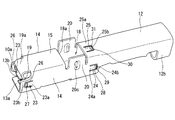
図8及び図9は第2実施形態を示し、前記スタビライザ20,20の基部20a、20aに対する切り込み部21,22を廃止して通常の案内機能のみとし、雌端子1の端子本体10の両側壁部14,14の前後位置と、上壁部15のランス孔18の近傍にばね部材としての弾性片23、24、25を複数設けたものである。
In the present embodiment, the protrusions 8 and 8 are provided in the terminal receiving hole 3 so as to apply a spring reaction force to the stabilizers 20 and 20, but outwardly on the outer surfaces of the stabilizers 20 and 20. It is also possible to apply a spring reaction force to each of the stabilizers 20 and 20 by providing facing protrusions integrally and bringing the protrusions into contact with the opposing inner side surfaces 3f and 3f of the terminal receiving hole 3. is there. In this case, since each said protrusion can be utilized as a reinforcement part of each stabilizer 20 and 20, it is further effective.
[Second Embodiment]
8 and 9 show a second embodiment, in which the notches 21 and 22 with respect to the base portions 20a and 20a of the stabilizers 20 and 20 are abolished so that only a normal guiding function is provided, and both side walls of the terminal body 10 of the female terminal 1 are provided. A plurality of elastic pieces 23, 24, 25 as spring members are provided in front and rear positions of the portions 14, 14 and in the vicinity of the lance hole 18 of the upper wall portion 15.

具体的に説明すると、前側の第1弾性片23,23は、前記両側壁部14,14に逆コ字形状の切り込み部26、26によって前後方向に長いほぼ矩形状に形成されて、切り込み残余部の各基部23a、23aを支点として先端部23b、23bが内外方へ弾性変形可能に形成されている。   Specifically, the first elastic pieces 23, 23 on the front side are formed in a substantially rectangular shape long in the front-rear direction by the inverted U-shaped cut portions 26, 26 on the both side wall portions 14, 14, and the remaining cut portion The tip portions 23b and 23b are formed so as to be elastically deformable inward and outward with the base portions 23a and 23a of the portion as fulcrums.

また、前記各第1弾性片23,23の先端部23b、23bの各外面には、突部27、27が一対に設けられている。この各突部27,27は、雌端子1をプレス成形する際に、エンボス加工によって一緒に形成され、上下方向に長い凸状に形成されている。   Further, a pair of protrusions 27 are provided on the outer surfaces of the tip portions 23b and 23b of the first elastic pieces 23 and 23, respectively. The protrusions 27 and 27 are formed together by embossing when the female terminal 1 is press-molded, and are formed in a convex shape that is long in the vertical direction.

後側の第2弾性片24、24は、第1弾性片23,23と同一の形状であり、前記両側壁部14,14にコ字形状の切り込み部28、28によって前後方向に長いほぼ矩形状に形成されて、切り込み残余部の各基部24a、24aを支点として先端部24b、24bが内外方へ弾性変形可能に形成されている。   The second elastic pieces 24, 24 on the rear side have the same shape as the first elastic pieces 23, 23, and are substantially rectangular long in the front-rear direction by the U-shaped cut portions 28, 28 on the side wall portions 14, 14. The tip portions 24b and 24b are formed in a shape so as to be elastically deformable inward and outward with the base portions 24a and 24a of the remaining cut portions as fulcrums.

また、前記各第2弾性片24,24の先端部24b、24bの外面には、同じく突部29、29が一対に設けられている。この各突部29,29も、雌端子1をプレス成形する際に、エンボス加工によって一緒に形成され、上下方向に長い凸状に形成されている。   Similarly, a pair of protrusions 29 and 29 are provided on the outer surfaces of the tip portions 24b and 24b of the second elastic pieces 24 and 24, respectively. The protrusions 29 and 29 are also formed together by embossing when the female terminal 1 is press-molded, and are formed in a convex shape that is long in the vertical direction.

上壁部15側の一つの第3弾性片25は、第2弾性片24と同一の形状であり、前記上壁部15にコ字形状の切り込み部30によって前後方向に長いほぼ矩形状に形成されて、切り込み残余部の基部25aを支点として先端部25bが上下方向へ弾性変形可能に形成されている。   One third elastic piece 25 on the upper wall portion 15 side has the same shape as the second elastic piece 24 and is formed in a substantially rectangular shape that is long in the front-rear direction by a U-shaped cut portion 30 in the upper wall portion 15. Thus, the distal end portion 25b is formed to be elastically deformable in the vertical direction with the base portion 25a of the remaining cut portion as a fulcrum.

また、前記第3弾性片25の先端部25bの外面には、同じく突部31が一対に設けられている。この突部31も、雌端子1をプレス成形する際に、エンボス加工によって一緒に形成され、上下方向に長い凸状に形成されている。   Similarly, a pair of protrusions 31 are provided on the outer surface of the tip 25b of the third elastic piece 25. The protrusion 31 is also formed together by embossing when the female terminal 1 is press-molded, and is formed in a convex shape that is long in the vertical direction.

したがって、この実施形態によれば、雌端子1を端子収容室3の一端開口3aから内部へ挿入して行くと、まず、端子本体10の先端側に形成された前記両第1弾性片23,23の各突部27,27が端子収容室3の内側面3f、3fに弾接して、第1弾性片23,23の先端部23b、23b側が基部23a、23aを支点として互いに内方へばね反力をもって弾性変形する。続いて、第2弾性片24,24の先端部24b、24bが、内側面3f、3fに弾接した各突部29、29を介して基部24a、24aを支点として互いに内方へばね反力をもって弾性変形すると共に、第3弾性片25も前記上壁部2cの下面、つまり端子収容孔3の天井面3hに弾接した突部31を介して先端部25bが基部25aを支点として下方へばね反力をもって弾性変形する。   Therefore, according to this embodiment, when the female terminal 1 is inserted into the inside from the one end opening 3a of the terminal accommodating chamber 3, first, the first elastic pieces 23, 23 are elastically contacted with the inner side surfaces 3f and 3f of the terminal accommodating chamber 3, and the distal end portions 23b and 23b of the first elastic pieces 23 and 23 are springed inward with respect to the base portions 23a and 23a. Elastically deforms with reaction force. Subsequently, the distal end portions 24b, 24b of the second elastic pieces 24, 24 are spring reaction forces inward from each other with the base portions 24a, 24a serving as fulcrums via the projections 29, 29 elastically contacting the inner side surfaces 3f, 3f. The third elastic piece 25 also moves downward with the base portion 25a serving as a fulcrum through the protrusion 31 elastically contacting the lower surface of the upper wall portion 2c, that is, the ceiling surface 3h of the terminal accommodating hole 3. Elastically deforms with spring reaction force.

したがって、前記雌端子1は、前記ランス部4とランス孔18を介して端子収容孔3内に係止固定された状態では、前記第1〜3弾性片23〜25のばね反力によって横方向と上下方向から端子収容孔3内に弾持された形になる。   Therefore, the female terminal 1 is laterally moved by the spring reaction force of the first to third elastic pieces 23 to 25 in a state where the female terminal 1 is locked and fixed in the terminal receiving hole 3 via the lance portion 4 and the lance hole 18. In this manner, the terminal is held in the terminal receiving hole 3 from above and below.

このため、車両の振動などがコネクタハウジング2を介して雌端子1に伝達されると、前記第1〜3弾性片23〜25によってその振動が吸収されて雌端子1の振動を効果的に抑制することができる。   For this reason, when vehicle vibration or the like is transmitted to the female terminal 1 via the connector housing 2, the vibration is absorbed by the first to third elastic pieces 23 to 25, and the vibration of the female terminal 1 is effectively suppressed. can do.

この結果、前記車両の振動や雰囲気温度の変化などの外的要因で生じる前記雌端子1と雄端子16との間の微振動による接触位置のずれに起因した劣化を十分に抑制することが可能になる。   As a result, it is possible to sufficiently suppress the deterioration caused by the displacement of the contact position due to the slight vibration between the female terminal 1 and the male terminal 16 caused by external factors such as the vibration of the vehicle and the change in ambient temperature. become.

特に、本実施形態では、雌端子1に対して第1、第2弾性片23,24により横方向の振動を吸収できる他に、第3弾性片25によって上下方向の振動も吸収することができるから、雌端子1のさらなる振動抑制効果が得られる。この結果、雌端子1と雄端子16との間の微振動による接触位置のずれに起因した劣化をさらに抑制することができる。   In particular, in this embodiment, the first and second elastic pieces 23 and 24 can absorb lateral vibrations with respect to the female terminal 1, and the third elastic piece 25 can also absorb vertical vibrations. Therefore, the further vibration suppression effect of the female terminal 1 is obtained. As a result, it is possible to further suppress deterioration due to the displacement of the contact position due to the slight vibration between the female terminal 1 and the male terminal 16.

また、本実施形態も前記雌端子1の外壁の一部を利用して各弾性片23〜25を形成したので、部品点数の増加がなく、特に、第1実施形態のように、端子収容孔3の内側面3f、3fに突起部8,8を設ける必要もないので、既存のコネクタハウジング2を用いることが可能になる。したがって、この点でも製造コストの上昇を抑制できる。   Also, in this embodiment, the elastic pieces 23 to 25 are formed by using a part of the outer wall of the female terminal 1, so that there is no increase in the number of parts. In particular, as in the first embodiment, the terminal receiving hole Since it is not necessary to provide the projections 8 and 8 on the inner side surfaces 3f and 3f of the third connector 3, the existing connector housing 2 can be used. Therefore, an increase in manufacturing cost can also be suppressed in this respect.

本実施形態では、雌端子1の上壁部15に設けられた前記第3弾性片25の他に、下側底壁部13bの前記第3弾性片25と対応する位置に、同じ構造の第4弾性片を設けることも可能である。   In the present embodiment, in addition to the third elastic piece 25 provided on the upper wall portion 15 of the female terminal 1, a second structure having the same structure is provided at a position corresponding to the third elastic piece 25 of the lower bottom wall portion 13 b. It is also possible to provide four elastic pieces.

このようにすれば、前記雌端子1に対する端子収容孔3内での上下方向の弾性的な保持がさらに効果的になる。   In this way, the elastic holding in the vertical direction in the terminal accommodating hole 3 with respect to the female terminal 1 becomes more effective.

本発明は、前記実施形態の構成に限定されるものではなく、例えば、前記ばね部材の構造をさらに変更することも可能であり、例えば、弾性片を三角形状や半円状に形成することも可能である。   The present invention is not limited to the configuration of the above-described embodiment. For example, the structure of the spring member can be further changed. For example, the elastic piece can be formed in a triangular shape or a semicircular shape. Is possible.

また、前記ランス孔18の前端孔縁18aに、前記ランス部4の係止溝4cに係止する突部などを設けることも可能である。   Further, it is possible to provide a protrusion or the like that engages with the engaging groove 4 c of the lance portion 4 at the front end hole edge 18 a of the lance hole 18.

前記実施形態から把握される前記請求項以外の発明の技術的思想について以下に説明する。
〔請求項a〕請求項2に記載の雌端子構造において、
前記スタビライザの切り込み部を、基部の両側縁の上下方向にのみ形成したことを特徴とする雌端子構造。
〔請求項b〕請求項2に記載の雌端子構造において、
前記スタビライザの切り込み部を、基部の両側縁の上下方向に形成すると共に、少なくとも一方の切り込み部の端縁から水平方向の切り込み部を形成したことを特徴とする雌端子構造。
〔請求項c〕請求項2に記載の雌端子構造において、
前記スタビライザの先端部の外面に、前記端子収容孔の内側面に弾接する突部を一体に設けたことを特徴とする雌端子構造。
〔請求項d〕請求項3に記載の雌端子構造において、
前記弾性片を、端子本体の両側壁部と上壁部に設けたことを特徴とする雌端子構造。
The technical ideas of the invention other than the claims ascertained from the embodiment will be described below.
[Claim a] In the female terminal structure according to claim 2,
A female terminal structure in which the notch portion of the stabilizer is formed only in the vertical direction of both side edges of the base portion.
[B] In the female terminal structure according to claim 2,
A female terminal structure in which a cut portion of the stabilizer is formed in the vertical direction of both side edges of the base portion, and a horizontal cut portion is formed from an edge of at least one of the cut portions.
[Claim c] In the female terminal structure according to claim 2,
A female terminal structure characterized in that a protrusion that elastically contacts the inner surface of the terminal receiving hole is integrally provided on the outer surface of the tip of the stabilizer.
[Claim d] In the female terminal structure according to claim 3,
A female terminal structure in which the elastic pieces are provided on both side walls and an upper wall of a terminal body.

1…雌端子
2…コネクタハウジング
2a…底壁
2b…両側壁(外壁)
2c…上壁
3…端子収容孔
3a…一端開口
3b…他端開口
3f…内側面
4…ランス部
4a…基端部
4b…先端部
4c…係止溝
5…空間部
10…端子本体
12…バレル部
13…底壁部
14…両側壁部
15…上壁部
16…雄端子
17…接触ビード
18…ランス孔
18a…前端孔縁
19…接点ばね
20…スタビライザ(ばね部材)
20a…基部
21・22…第1、第2切り込み部
22a…第3切り込み部
23・24・25…弾性片(ばね部材)
26・28・30…切り込み部
27・29・31…突部
DESCRIPTION OF SYMBOLS 1 ... Female terminal 2 ... Connector housing 2a ... Bottom wall 2b ... Both side wall (outer wall)
2c ... Upper wall 3 ... Terminal receiving hole 3a ... One end opening 3b ... Other end opening 3f ... Inner side surface 4 ... Lance portion 4a ... Base end portion 4b ... Tip end portion 4c ... Locking groove 5 ... Space portion 10 ... Terminal body 12 ... Barrel part 13 ... Bottom wall part 14 ... Both side wall parts 15 ... Upper wall part 16 ... Male terminal 17 ... Contact bead 18 ... Lance hole 18a ... Front end hole edge 19 ... Contact spring 20 ... Stabilizer (spring member)
20a ... base parts 21 and 22 ... first and second cut parts 22a ... third cut parts 23, 24 and 25 ... elastic pieces (spring members)
26, 28, 30 ... notches 27, 29, 31 ... protrusions

Claims (4)

コネクタハウジングに形成された端子収容孔に長手方向の一端開口から挿入されて、前記端子収容孔の内壁に形成された係止部に係止して保持されると共に、前端側から内部に挿入された雄端子が弾性的に接触する接点を内部に有する雌端子構造において、
前記雌端子の外壁の所定位置に、前記外壁の一部を切り込んで形成され、前記端子収容孔の内壁面に弾接するばね部材を設けたことを特徴とする雌端子構造。
It is inserted into the terminal receiving hole formed in the connector housing from one end opening in the longitudinal direction, is held by being locked to the locking portion formed on the inner wall of the terminal receiving hole, and is inserted into the inside from the front end side. In the female terminal structure having a contact inside which the male terminal is elastically contacted,
A female terminal structure comprising a spring member formed by cutting a part of the outer wall at a predetermined position on the outer wall of the female terminal and elastically contacting the inner wall surface of the terminal receiving hole.
請求項1に記載の雌端子構造において、
前記雌端子は、前記外壁を構成する両側壁の外端縁から軸直角方向へ延出したスタビライザを有し、
該スタビライザの固定側基部の両側縁から前記両側壁側へ向かって切り込まれた切り込み部を形成すると共に、該切り込み部によって前記スタビライザを、前記端子収容孔の内側面に弾接可能な前記ばね部材として構成したことを特徴とする雌端子構造。
In the female terminal structure according to claim 1,
The female terminal has a stabilizer extending in the direction perpendicular to the axis from the outer edge of both side walls constituting the outer wall,
The spring that forms notches from both side edges of the fixed base portion of the stabilizer toward the both side walls, and allows the stabilizer to elastically contact the inner surface of the terminal receiving hole by the notches. A female terminal structure configured as a member.
前記請求項1に記載の雌端子構造において、
前記雌端子の前記外壁を構成する少なくとも両側壁に、外周縁がほぼコ字形状に切り込まれて形成された弾性片を設け、該弾性片を前記ばね部材として構成すると共に、該弾性片の外側面に、前記端子収容孔の内側面に弾接する突部を形成したことを特徴とする雌端子も接続構造。
In the female terminal structure according to claim 1,
An elastic piece formed by cutting an outer peripheral edge into a substantially U shape is provided on at least both side walls constituting the outer wall of the female terminal, and the elastic piece is configured as the spring member. A female terminal connecting structure is also characterized in that a protruding portion elastically contacting the inner side surface of the terminal receiving hole is formed on the outer side surface.
請求項2に記載の雌端子構造において、
前記端子収容孔の内側面に、前記スタビライザが弾接する突起部を設けたことを特徴とする雌端子構造。
In the female terminal structure according to claim 2,
A female terminal structure characterized in that a protrusion for elastic contact with the stabilizer is provided on an inner surface of the terminal receiving hole.
JP2015082906A 2015-04-15 2015-04-15 Female terminal structure Abandoned JP2016207251A (en)

Priority Applications (1)

Application Number Priority Date Filing Date Title
JP2015082906A JP2016207251A (en) 2015-04-15 2015-04-15 Female terminal structure

Applications Claiming Priority (1)

Application Number Priority Date Filing Date Title
JP2015082906A JP2016207251A (en) 2015-04-15 2015-04-15 Female terminal structure

Publications (1)

Publication Number Publication Date
JP2016207251A true JP2016207251A (en) 2016-12-08

Family

ID=57487734

Family Applications (1)

Application Number Title Priority Date Filing Date
JP2015082906A Abandoned JP2016207251A (en) 2015-04-15 2015-04-15 Female terminal structure

Country Status (1)

Country Link
JP (1) JP2016207251A (en)

Cited By (1)

* Cited by examiner, † Cited by third party
Publication number Priority date Publication date Assignee Title
EP3435491A1 (en) * 2017-07-24 2019-01-30 Hirose Electric Co., Ltd. Terminal with contact piece, connector, and connector device

Citations (6)

* Cited by examiner, † Cited by third party
Publication number Priority date Publication date Assignee Title
JPH0189474U (en) * 1987-12-04 1989-06-13
JP2003045545A (en) * 2001-08-02 2003-02-14 Auto Network Gijutsu Kenkyusho:Kk Connector
JP2005044598A (en) * 2003-07-28 2005-02-17 Sumitomo Wiring Syst Ltd Terminal fitting
JP2012043741A (en) * 2010-08-23 2012-03-01 Yazaki Corp Connector
WO2014125963A1 (en) * 2013-02-12 2014-08-21 矢崎総業株式会社 Connector
JP2016173898A (en) * 2015-03-16 2016-09-29 住鉱テック株式会社 Connector, and female terminal

Patent Citations (6)

* Cited by examiner, † Cited by third party
Publication number Priority date Publication date Assignee Title
JPH0189474U (en) * 1987-12-04 1989-06-13
JP2003045545A (en) * 2001-08-02 2003-02-14 Auto Network Gijutsu Kenkyusho:Kk Connector
JP2005044598A (en) * 2003-07-28 2005-02-17 Sumitomo Wiring Syst Ltd Terminal fitting
JP2012043741A (en) * 2010-08-23 2012-03-01 Yazaki Corp Connector
WO2014125963A1 (en) * 2013-02-12 2014-08-21 矢崎総業株式会社 Connector
JP2016173898A (en) * 2015-03-16 2016-09-29 住鉱テック株式会社 Connector, and female terminal

Cited By (2)

* Cited by examiner, † Cited by third party
Publication number Priority date Publication date Assignee Title
EP3435491A1 (en) * 2017-07-24 2019-01-30 Hirose Electric Co., Ltd. Terminal with contact piece, connector, and connector device
CN109301540A (en) * 2017-07-24 2019-02-01 广濑电机株式会社 Terminal, connector and electrical connector with contact chip

Similar Documents

Publication Publication Date Title
JP4207952B2 (en) connector
JP6119524B2 (en) Terminal fitting
JP6342708B2 (en) Connector and terminal fitting connection structure
JP6367746B2 (en) Connector and electrical connection device
US9356386B2 (en) Connector
JP2007324029A (en) Terminal for electric connection, and connector using it
US11005203B2 (en) Terminal module
JP5999510B2 (en) Female terminal fitting and manufacturing method thereof
KR20170070997A (en) Locking structure of connector and connector
JP6016661B2 (en) connector
US20190245293A1 (en) Terminal module and connector
JP7144191B2 (en) movable connector
JP4034801B2 (en) Electrical connector
JP2016207251A (en) Female terminal structure
JP5881891B2 (en) Electronic component assembly structure and electrical junction box
JP2016207253A (en) Connection structure for connector and terminal fitting
JP2016207252A (en) Female terminal structure
JP2016207254A (en) Connection structure for connector and terminal fitting
JP6746357B2 (en) Connector terminals and connectors
JP7271775B2 (en) movable connector
JP5773553B1 (en) Terminal fitting
JP5836623B2 (en) connector
JP6497989B2 (en) connector
JP2007207676A (en) Electrical connector
JP2023092966A (en) connector

Legal Events

Date Code Title Description
A621 Written request for application examination

Free format text: JAPANESE INTERMEDIATE CODE: A621

Effective date: 20180316

A977 Report on retrieval

Free format text: JAPANESE INTERMEDIATE CODE: A971007

Effective date: 20181109

A131 Notification of reasons for refusal

Free format text: JAPANESE INTERMEDIATE CODE: A131

Effective date: 20181120

A762 Written abandonment of application

Free format text: JAPANESE INTERMEDIATE CODE: A762

Effective date: 20181218