JP2016206410A - Zoom lens and imaging apparatus - Google Patents
Zoom lens and imaging apparatus Download PDFInfo
- Publication number
- JP2016206410A JP2016206410A JP2015087844A JP2015087844A JP2016206410A JP 2016206410 A JP2016206410 A JP 2016206410A JP 2015087844 A JP2015087844 A JP 2015087844A JP 2015087844 A JP2015087844 A JP 2015087844A JP 2016206410 A JP2016206410 A JP 2016206410A
- Authority
- JP
- Japan
- Prior art keywords
- lens
- lens group
- zoom
- group
- zoom lens
- Prior art date
- Legal status (The legal status is an assumption and is not a legal conclusion. Google has not performed a legal analysis and makes no representation as to the accuracy of the status listed.)
- Granted
Links
Images


Classifications
-
- G—PHYSICS
- G02—OPTICS
- G02B—OPTICAL ELEMENTS, SYSTEMS OR APPARATUS
- G02B15/00—Optical objectives with means for varying the magnification
- G02B15/14—Optical objectives with means for varying the magnification by axial movement of one or more lenses or groups of lenses relative to the image plane for continuously varying the equivalent focal length of the objective
Abstract
Description
本件発明は、ズームレンズ及び撮像装置に関し、特に、デジタルスチルカメラやデジタルビデオカメラ等の固体撮像素子を用いた撮像装置に好適なズームレンズ及び当該ズームレンズを備えた撮像装置に関する。 The present invention relates to a zoom lens and an imaging apparatus, and more particularly to a zoom lens suitable for an imaging apparatus using a solid-state imaging device such as a digital still camera or a digital video camera, and an imaging apparatus including the zoom lens.
従来より、デジタルスチルカメラ、デジタルビデオカメラ等の固体撮像素子を用いた撮像装置が普及している。これらの撮像装置は、監視用撮像装置など種々の目的で用いられている。近年、固体撮像素子の高画素化の進展に伴い、被写体の細かな特徴を確認可能なフルハイビジョン方式に対応した高性能な変倍比の高い小型のズームレンズが求められるようになっている。 Conventionally, imaging devices using solid-state imaging devices such as digital still cameras and digital video cameras have become widespread. These imaging devices are used for various purposes such as a monitoring imaging device. In recent years, as the number of pixels of a solid-state image sensor increases, there is a demand for a compact zoom lens with a high performance and a high zoom ratio that is compatible with the full high-definition method capable of confirming fine features of a subject.
このようなズームレンズとして、従来より4群構成のズームレンズが広く知られている(例えば、「特許文献1」参照。)。特許文献1に記載のズームレンズは、物体側から順に配置された、正、負、正、正の第1のレンズ群から第4のレンズ群を備え、第1レンズ群と第3レンズ群を固定させたまま、第2レンズ群を光軸方向に沿って一方向に移動させることで変倍を行う。また、第4レンズ群を光軸方向に沿って前後方向に移動させることによって変倍に伴う像面変動の補正やフォーカシングを行う。このような4群構成のズームレンズは、変倍域全域において高い結像性能を実現することができるとしている。この特許文献1に記載のズームレンズは25倍程度の変倍比を達成している。
As such a zoom lens, a zoom lens having a four-group configuration has been widely known (for example, see “
近年、より変倍比の高いズームレンズが求められ、5群構成のズームレンズが提案されるようになってきた(例えば、「特許文献2」及び「特許文献3」参照。)。例えば、特許文献2及び特許文献3に記載のズームレンズは、上記4群構成のズームレンズの像側に固定群を追加したような構成を有している。すなわち、これらのズームレンズでは、物体側から順に配置された、正、負、正、正、負の第1レンズ群から第5レンズ群を備え、第1レンズ群と第3レンズ群と第5レンズ群を固定させたまま、第2レンズ群を光軸方向に沿って一方向に移動させることにより変倍を行い、第4レンズ群を光軸方向に沿って前後方向に移動させることによって変倍に伴う像面変動の補正やフォーカシングを行うものとしている。特許文献2に記載のズームレンズの変倍比は35倍程度、特許文献3に記載のズームレンズの変倍比は30倍程度であり、特許文献1に記載のズームレンズと比較すると高い変倍比を実現している。
In recent years, zoom lenses with higher zoom ratios have been demanded, and zoom lenses with a five-group configuration have been proposed (see, for example, “Patent Document 2” and “Patent Document 3”). For example, the zoom lenses described in Patent Document 2 and Patent Document 3 have a configuration in which a fixed group is added to the image side of the zoom lens having the four-group configuration. That is, these zoom lenses include positive, negative, positive, positive, negative first to fifth lens groups arranged in order from the object side, and the first, third, and fifth lens groups. With the lens group fixed, zooming is performed by moving the second lens group in one direction along the optical axis direction, and changing by moving the fourth lens group in the front-rear direction along the optical axis direction. It is assumed that image plane fluctuation correction and focusing associated with doubling are performed. The zoom lens described in Patent Document 2 has a zoom ratio of about 35 times, and the zoom lens described in Patent Document 3 has a zoom ratio of about 30 times, which is higher than that of the zoom lens described in
しかしながら、特許文献2に記載のズームレンズでは高い変倍比を実現しているものの、変倍に伴う収差変動が大きく、変倍域全域において良好な光学性能を実現することが困難であった。一方、特許文献3に記載のズームレンズでは、変倍に伴う収差変動が抑制されており、変倍域全域において良好な光学性能を実現しているものの、特許文献2に記載のズームレンズと比較すると変倍比は低い。 However, although the zoom lens described in Patent Document 2 achieves a high zoom ratio, the aberration variation accompanying the zooming is large, and it is difficult to realize good optical performance over the entire zoom range. On the other hand, the zoom lens described in Patent Document 3 suppresses fluctuations in aberrations associated with zooming, and achieves good optical performance over the entire zooming range, but is compared with the zoom lens described in Patent Document 2. Then the zoom ratio is low.
本発明の課題は、高い変倍比を有し、且つ、変倍域全域にわたって良好な光学性能を有する小型のズームレンズを提供することにある。 An object of the present invention is to provide a small zoom lens having a high zoom ratio and having good optical performance over the entire zoom range.
上記課題を解決するために、本件発明に係るズームレンズは、物体側から順に配置された、第1レンズ群、第2レンズ群、第3レンズ群、第4レンズ群、第5レンズ群及び第6レンズ群から構成され、前記第5レンズ群は負の屈折力を有し、少なくとも当該第5レンズ群を移動させることで広角端から望遠端への変倍を行い、以下の条件式を満足することを特徴とする。 In order to solve the above problems, a zoom lens according to the present invention includes a first lens group, a second lens group, a third lens group, a fourth lens group, a fifth lens group, and a first lens group, which are arranged in order from the object side. The fifth lens group has negative refracting power, and zooming from the wide-angle end to the telephoto end is performed by moving at least the fifth lens group, and the following conditional expression is satisfied: It is characterized by doing.
(1) 4.0< β5T <6.0
ただし、
β5Tは、望遠端における前記第5レンズ群の横倍率である。
(1) 4.0 <β5T <6.0
However,
β5T is the lateral magnification of the fifth lens group at the telephoto end.
本件発明に係るズームレンズは、前記ズームレンズの像側に、前記ズームレンズによって形成された光学像を電気的信号に変換する撮像素子を備えたことを特徴とする。 The zoom lens according to the present invention is characterized in that an image sensor for converting an optical image formed by the zoom lens into an electrical signal is provided on the image side of the zoom lens.
本件発明によれば、高い変倍比を有し、且つ、変倍域全域にわたって良好な光学性能を有する小型のズームレンズを提供することができる。 According to the present invention, it is possible to provide a small zoom lens having a high zoom ratio and having good optical performance over the entire zoom range.
以下、本件発明に係るズームレンズ及び撮像装置の実施の形態を説明する。 Embodiments of a zoom lens and an imaging apparatus according to the present invention will be described below.
1.ズームレンズ
1−1.光学系の構成
本実施の形態のズームレンズは、物体側から順に配置された、第1レンズ群、第2レンズ群、第3レンズ群、第4レンズ群、第5レンズ群及び第6レンズ群から構成され、前記第5レンズ群は負の屈折力を有し、少なくとも当該第5レンズ群を移動させることで広角端から望遠端への変倍を行い、後述する条件式(1)を満足することを特徴とする。
1. Zoom lens 1-1. Configuration of Optical System The zoom lens according to the present embodiment includes a first lens group, a second lens group, a third lens group, a fourth lens group, a fifth lens group, and a sixth lens group, which are arranged in order from the object side. The fifth lens group has a negative refractive power, and at least the fifth lens group is moved to perform zooming from the wide-angle end to the telephoto end, and satisfies conditional expression (1) described later It is characterized by doing.
本実施の形態のズームレンズでは、上記6群構成を採用するとともに、後述する条件式(1)を満足させることにより、各レンズ群間の間隔(空気間隔)を変化させることで高い変倍比を有し、且つ、変倍域全域にわたって良好な光学性能を有する小型のズームレンズを得ることができる。なお、変倍時及び合焦時の動作と条件式に関する事項は後述する。 In the zoom lens according to the present embodiment, the above six-group configuration is adopted, and a conditional expression (1) to be described later is satisfied, so that a high zoom ratio can be obtained by changing an interval (air interval) between the lens groups. And a small zoom lens having good optical performance over the entire zoom range. Note that the matters concerning the operation and conditional expressions at the time of zooming and focusing will be described later.
本実施の形態のズームレンズにおいて、第5レンズ群の屈折力が負であれば、他のレンズ群の屈折力は特に限定されるものではなく、当該ズームレンズに要求される変倍比、光学性能等に応じて適宜適切なパワー配置を採用することができる。以下、各レンズ群の構成等について説明する。 In the zoom lens of the present embodiment, as long as the refractive power of the fifth lens group is negative, the refractive power of the other lens groups is not particularly limited, and the zoom ratio and optical power required for the zoom lens are not limited. An appropriate power arrangement can be adopted as appropriate according to performance and the like. The configuration of each lens group will be described below.
(1)第1レンズ群及び第2レンズ群
本実施の形態のズームレンズにおいて、第1レンズ群及び第2レンズ群の屈折力は限定されるものではなく、各レンズ群の具体的なレンズ構成も特に限定されるものではない。例えば、当該第1レンズ群を正の屈折力のレンズ群とし、第2レンズ群を負の屈折力のレンズ群とすれば、変倍比が高く、望遠端における焦点距離の長いズームレンズを実現することが容易になる。これと同時に、当該ズームレンズ全系の全長が長くなるのを抑制することができ、小型のズームレンズを得ることが容易になる。
(1) First lens group and second lens group In the zoom lens of the present embodiment, the refractive powers of the first lens group and the second lens group are not limited, and specific lens configurations of each lens group Is not particularly limited. For example, if the first lens group is a positive refractive power lens group and the second lens group is a negative refractive power lens group, a zoom lens with a high zoom ratio and a long focal length at the telephoto end can be realized. Easy to do. At the same time, it is possible to suppress an increase in the overall length of the entire zoom lens system, and it becomes easy to obtain a small zoom lens.
例えば、第1レンズ群を正の屈折力のレンズ群としたとき、当該第1レンズ群を物体側から順に配置された、1枚の負レンズおよび1枚の正レンズからなる接合レンズと、少なくとも1枚の正の単レンズとを備える構成とすることができる。このように構成することで、望遠端における球面収差の補正が容易になり、特に望遠端における光学性能をより向上することができる。 For example, when the first lens group is a lens group having a positive refractive power, at least a cemented lens including one negative lens and one positive lens arranged in order from the object side, It can be set as the structure provided with one positive single lens. With this configuration, it becomes easy to correct spherical aberration at the telephoto end, and in particular, the optical performance at the telephoto end can be further improved.
また、第2レンズ群を負の屈折力のレンズ群としたとき、少なくとも1枚の正レンズを含む構成とすることが好ましい。このように構成することで、色収差補正等を良好に行うことができ、より光学性能の高いズームレンズを得ることができる。 Further, when the second lens group is a lens group having a negative refractive power, it is preferable that the second lens group includes at least one positive lens. With this configuration, chromatic aberration correction and the like can be performed favorably, and a zoom lens with higher optical performance can be obtained.
(2)第3レンズ群及び第4レンズ群
本実施の形態のズームレンズにおいて、第3レンズ群及び第4レンズ群の屈折力は特に限定されるものではなく、各レンズ群の具体的なレンズ構成も特に限定されるものではない。例えば、第3レンズ群及び第4レンズ群をそれぞれ正の屈折力のレンズ群とすれば、変倍域全域にわたって、球面収差、コマ収差及び像面湾曲の補正が容易になり、良好な光学性能を実現することが容易になる。
(2) Third lens group and fourth lens group In the zoom lens of the present embodiment, the refractive powers of the third lens group and the fourth lens group are not particularly limited, and specific lenses of each lens group The configuration is not particularly limited. For example, if each of the third lens group and the fourth lens group is a lens group having a positive refractive power, it is easy to correct spherical aberration, coma aberration, and field curvature over the entire zoom range, and good optical performance. It becomes easy to realize.
例えば、第3レンズ群を正の屈折力のレンズ群としたとき、少なくとも1枚の正レンズを含み、当該正レンズの少なくとも1面が非球面とすることが好ましい。この場合、変倍比の高いズームレンズとした場合も、変倍域全域において、球面収差及びコマ収差の補正を良好に行うことができる。 For example, when the third lens group is a lens group having a positive refractive power, it is preferable that at least one positive lens is included and at least one surface of the positive lens is an aspherical surface. In this case, even when the zoom lens has a high zoom ratio, correction of spherical aberration and coma aberration can be satisfactorily performed over the entire zoom range.
また、第3レンズ群を正の屈折力のレンズ群としたとき、少なくとも1枚の負レンズを含むことも好ましい。例えば、第3レンズ群を1枚の正レンズと1枚の負レンズとから構成することにより、少ないレンズ枚数で、高解像力のズームレンズを実現することができ、ズームレンズの小型化、軽量化及び低コスト化を図ることができる。ただし、第3レンズ群を1枚の正レンズと1枚の負レンズとから構成した場合、上述した理由から、この正レンズの少なくとも1面が非球面であることがより好ましい。 In addition, when the third lens group is a lens group having a positive refractive power, it is preferable that at least one negative lens is included. For example, by configuring the third lens group with one positive lens and one negative lens, a zoom lens with high resolution can be realized with a small number of lenses, and the zoom lens can be reduced in size and weight. In addition, cost reduction can be achieved. However, when the third lens group is composed of one positive lens and one negative lens, it is more preferable that at least one surface of the positive lens is aspherical for the reason described above.
(3)第5レンズ群
第5レンズ群は、負の屈折力を有するレンズ群であり、後述する条件式(1)を満足する限り、その具体的なレンズ構成は特に限定されるものではない。ただし、第5レンズ群を1枚の負レンズにより構成することで、当該ズームレンズの小型化及び軽量化を図ることができる。
(3) Fifth Lens Group The fifth lens group is a lens group having negative refractive power, and its specific lens configuration is not particularly limited as long as conditional expression (1) described later is satisfied. . However, the zoom lens can be reduced in size and weight by forming the fifth lens group with one negative lens.
(4)第6レンズ群
第6レンズ群の屈折力及び具体的なレンズ構成は特に限定されるものではないが、当該ズームレンズの小型化を図る上で、第6レンズ群は正の屈折力を有することが好ましい。最も像面側に配置されるレンズ群の屈折力を正にすることにより、バックフォーカスを短くすることができ、ズームレンズ全系の全長を短くすることができる。また、第6レンズ群は1枚のレンズから構成することが好ましい。このように構成することで、当該ズームレンズの小型化及び軽量化を図ることができる。
(4) Sixth lens group The refractive power and specific lens configuration of the sixth lens group are not particularly limited, but the sixth lens group has a positive refractive power in order to reduce the size of the zoom lens. It is preferable to have. By making the refractive power of the lens group arranged closest to the image plane positive, the back focus can be shortened, and the overall length of the entire zoom lens system can be shortened. The sixth lens group is preferably composed of a single lens. With this configuration, the zoom lens can be reduced in size and weight.
(5)絞り
本件発明に係るズームレンズにおいて、絞りの配置は特に限定されるものではない。絞りが当該ズームレンズ内のどの位置に配置された場合であっても、本件発明に係る光学的効果を得ることができる。また、当該絞りは、像面に対して固定であってもよいし、移動可能に構成されてもよい。しかしながら、当該ズームレンズの大口径化を実現しながら、径方向の小型化を図るという観点から、第3レンズ群の物体側に絞りを配置することが好ましい。
(5) Diaphragm In the zoom lens according to the present invention, the arrangement of the iris is not particularly limited. The optical effect according to the present invention can be obtained regardless of the position of the stop in the zoom lens. Further, the stop may be fixed with respect to the image plane, or may be configured to be movable. However, it is preferable to dispose a stop on the object side of the third lens group from the viewpoint of reducing the size in the radial direction while realizing a large aperture of the zoom lens.
1−2.変倍時の動作
次に、本実施の形態のズームレンズの変倍時における動作を説明する。当該ズームレンズでは、広角端から望遠端への変倍の際に、負の屈折力を有する第5レンズ群を移動させる。これにより、変倍に伴う結像位置の変化を抑制することができ、変倍比の高いズームレンズとしたときも、変倍域全域にわたって良好な光学性能を実現することができる。
1-2. Next, an operation at the time of zooming of the zoom lens according to the present embodiment will be described. In the zoom lens, the fifth lens group having negative refractive power is moved during zooming from the wide-angle end to the telephoto end. Thereby, it is possible to suppress the change in the imaging position accompanying the zooming, and it is possible to realize a good optical performance over the entire zooming range even when the zoom lens has a high zooming ratio.
本実施の形態のズームレンズにおいて、変倍時における第5レンズ群以外の各レンズ群の具体的な動作は特に限定されるものではない。しかしながら、本件発明の課題を解決する上で、広角端から望遠端にかけて変倍する際に、各レンズ群の動作は以下のとおりであることが好ましい。 In the zoom lens according to the present embodiment, the specific operation of each lens group other than the fifth lens group at the time of zooming is not particularly limited. However, in order to solve the problem of the present invention, it is preferable that the operation of each lens group is as follows when zooming from the wide-angle end to the telephoto end.
(1)第1レンズ群
第1レンズ群は、固定群とすることが好ましい。ズームレンズの場合、一般に、第1レンズ群を構成するレンズは、他のレンズ群を構成するレンズよりも外径が大きく、重い。このため、第1レンズ群を固定群とすることにより、変倍時に移動する移動群を駆動するための駆動機構等の小型化を図ることができる。また、第1レンズ群を固定群とすることにより、変倍時における重心位置の移動を防止することができる。さらに、当該ズームレンズ全系の全長が変化せず、鏡筒構成を簡素にすることができる。ただし、当該ズームレンズ全系の全長とは、第1レンズ群において最も物体側に配置されたレンズの物体面と、像面との間の光軸上の距離をいう。
(1) First lens group The first lens group is preferably a fixed group. In the case of a zoom lens, generally, the lenses constituting the first lens group have a larger outer diameter and are heavier than the lenses constituting the other lens groups. For this reason, by using the first lens group as a fixed group, it is possible to reduce the size of a drive mechanism or the like for driving a moving group that moves during zooming. Further, by making the first lens group a fixed group, it is possible to prevent the movement of the center of gravity position during zooming. Further, the entire length of the entire zoom lens system does not change, and the lens barrel configuration can be simplified. However, the total length of the entire zoom lens system means a distance on the optical axis between the object plane of the lens arranged closest to the object side in the first lens group and the image plane.
(2)第2レンズ群
第2レンズ群は、広角端から望遠端への変倍の際に、第1レンズ群及び第2レンズ群の間隔が大きくなり、第2レンズ群及び第3レンズ群の間隔が小さくなるように移動することが好ましい。第2レンズ群を移動させることにより高変倍比のズームレンズを得ることが容易になる。
(2) Second lens group In the second lens group, the distance between the first lens group and the second lens group becomes large during zooming from the wide-angle end to the telephoto end, and the second lens group and the third lens group It is preferable to move so as to reduce the interval. By moving the second lens group, it becomes easy to obtain a zoom lens having a high zoom ratio.
(3)第3レンズ群
第3レンズ群は、変倍の際に光軸方向に固定された固定群であってもよく、光軸方向に沿って移動する移動群であってもよい。しかしながら、より変倍比が高く、光学性能の高いズームレンズを得るという観点から、第3レンズ群は移動群であることが好ましい。変倍時に第2レンズ群と共に第3レンズ群を移動させることにより、第2レンズ群と第3レンズ群とで変倍作用を分担することができる。これにより、第2レンズ群のみに変倍作用を持たせる場合と比較すると、変倍時における収差変動を抑制することができる。このため、少ない枚数のレンズで収差補正を良好に行うことができ、高解像力のズームレンズ、すなわちより光学性能の高いズームレンズを小型に構成することができる。
(3) Third Lens Group The third lens group may be a fixed group that is fixed in the optical axis direction during zooming, or may be a moving group that moves along the optical axis direction. However, from the viewpoint of obtaining a zoom lens having a higher zoom ratio and higher optical performance, the third lens group is preferably a moving group. By moving the third lens group together with the second lens group at the time of zooming, the zooming action can be shared between the second lens group and the third lens group. Thereby, compared with the case where only the second lens group has a zooming action, it is possible to suppress aberration fluctuations during zooming. Therefore, aberration correction can be performed satisfactorily with a small number of lenses, and a zoom lens with high resolution, that is, a zoom lens with higher optical performance can be configured in a small size.
また、第3レンズ群を移動群とする場合、広角端から望遠端への変倍の際に、第3レンズ群を像側に向かって凹の軌跡を描くように移動させることが好ましい。変倍の際に第3レンズ群をこのように移動させることにより、変倍に伴う結像位置の変化を抑制することができ、変倍域全域において、高解像力のズームレンズを得ることができる。 Further, when the third lens group is a moving group, it is preferable to move the third lens group so as to draw a concave locus toward the image side during zooming from the wide-angle end to the telephoto end. By moving the third lens group in this way at the time of zooming, it is possible to suppress changes in the imaging position that accompanies zooming and to obtain a zoom lens with high resolution throughout the zooming range. .
(4)第4レンズ群
第4レンズ群は移動群及び固定群のいずれであってもよいが、移動群とすることが好ましい。変倍時に第4レンズ群を移動させることで、変倍に伴う結像位置の変化を抑制することができ、変倍域全域において、高解像力のズームレンズを得ることができる。
(4) Fourth Lens Group The fourth lens group may be either a moving group or a fixed group, but is preferably a moving group. By moving the fourth lens group at the time of zooming, it is possible to suppress changes in the imaging position that accompanies zooming, and it is possible to obtain a zoom lens with high resolution in the entire zooming range.
また、第4レンズ群を移動群とするとき、第3レンズ群と第4レンズ群との間隔が、広角端から中間焦点距離への変倍の際には小さくなり、中間焦点距離から望遠端への変倍の際には大きくなるように、第4レンズ群を第3レンズ群に対して相対的に移動させることが好ましい。変倍の際に、第3レンズ群と第4レンズ群との間隔をこのように変化させることにより、変倍に伴う結像位置の変化を抑制し、変倍域全域において、高解像力のズームレンズを得ることができる。この際、変倍に伴う結像位置の変化をより良好に抑制するという観点から、広角端から望遠端への変倍の際に、第3レンズ群及び第4レンズ群をそれぞれ異なる軌跡で像側に向かって凹の軌跡を描くように移動させることが好ましい。 Further, when the fourth lens group is a moving group, the distance between the third lens group and the fourth lens group is reduced when zooming from the wide angle end to the intermediate focal length, and from the intermediate focal length to the telephoto end. It is preferable to move the fourth lens group relative to the third lens group so as to increase when zooming. By changing the distance between the third lens unit and the fourth lens unit in this way during zooming, the change in the imaging position accompanying zooming is suppressed, and high-resolution zoom is achieved over the entire zooming range. A lens can be obtained. At this time, from the viewpoint of better suppressing the change in the imaging position due to zooming, the third lens group and the fourth lens group are imaged with different trajectories when zooming from the wide-angle end to the telephoto end. It is preferable to move so as to draw a concave locus toward the side.
(5)第6レンズ群
第6レンズ群は、固定群であることが好ましい。第6レンズ群を固定群とすることにより、移動群を移動させるための上記駆動機構の構成を簡素にすることができる。また、第1レンズ群及び第6レンズ群を固定群とすることで、鏡筒を密閉構造とすることが容易になり、鏡筒内に水や埃が進入するのを防止することができる。
(5) Sixth lens group The sixth lens group is preferably a fixed group. By using the sixth lens group as a fixed group, the configuration of the drive mechanism for moving the moving group can be simplified. In addition, by using the first lens group and the sixth lens group as fixed groups, it becomes easy to make the lens barrel have a sealed structure, and water and dust can be prevented from entering the lens barrel.
(6)絞り
上述したとおり、絞りは像面に対して固定であっても、移動可能に構成されていてもよい。しかしながら、第3レンズ群の物体側に絞りを配置した場合、変倍時に第3レンズ群を移動させるときは、絞りと第3レンズ群とを一体的に移動させることが好ましい。これにより、上述したとおり、当該ズームレンズの大口径化を実現しながら、径方向の小型化を図ることができる。
(6) Diaphragm As described above, the iris may be fixed with respect to the image plane or configured to be movable. However, when the stop is disposed on the object side of the third lens group, it is preferable to move the stop and the third lens group integrally when moving the third lens group during zooming. As a result, as described above, it is possible to reduce the size in the radial direction while realizing an increase in the diameter of the zoom lens.
1−3.合焦時の動作
当該ズームレンズにおいて、合焦群は特に限定されるものではないが、第4レンズ群を合焦群とすることが好ましい。本実施の形態のズームレンズの構成では、第4レンズ群を比較的外径の小さいレンズで構成することができ、合焦群の小型化及び軽量化を図ることができ、迅速なフォーカシングが可能になる。また、合焦群の移動量を小さくすることができるため、当該ズームレンズ全系の全長の小型化を図ることができる。
1-3. Operation at the time of focusing In the zoom lens, the focusing group is not particularly limited, but the fourth lens group is preferably the focusing group. In the configuration of the zoom lens according to the present embodiment, the fourth lens group can be configured with a lens having a relatively small outer diameter, the focusing group can be reduced in size and weight, and rapid focusing is possible. become. In addition, since the amount of movement of the focusing group can be reduced, the overall length of the entire zoom lens system can be reduced.
1−4.防振時の動作
当該ズームレンズは、いわゆる防振群を備えてもよい。ここで、防振群とは、光軸に対して略垂直方向に移動可能に構成された1枚又は複数枚のレンズからなるレンズ群をいう。防振群を光軸に対して略垂直方向に移動させることで、光軸に対して略垂直方向に像を移動させることができる。これにより、手振れ等の撮像時の振動に伴う像ブレを補正することができる。
1-4. Operation at the time of image stabilization The zoom lens may include a so-called image stabilization group. Here, the anti-vibration group refers to a lens group including one or a plurality of lenses configured to be movable in a direction substantially perpendicular to the optical axis. By moving the image stabilizing group in a direction substantially perpendicular to the optical axis, the image can be moved in a direction substantially perpendicular to the optical axis. Thereby, it is possible to correct image blur due to vibration during imaging such as camera shake.
当該ズームレンズを構成するレンズ群のうち、いずれか一のレンズ群を防振群とすることができる。また、当該ズームレンズを構成するいずれか一のレンズ群の一部を防振群としてもよい。例えば、第2レンズ群を防振群とすることにより、上記撮像時の振動に伴う像ブレを補正する際の防振群の移動量を小さくすることができる。 Any one of the lens groups constituting the zoom lens can be used as an anti-vibration group. Further, a part of any one of the lens groups constituting the zoom lens may be set as the image stabilization group. For example, by using the second lens group as an image stabilization group, it is possible to reduce the amount of movement of the image stabilization group when correcting image blur due to vibration during imaging.
1−5.条件式
次に、各条件式について説明する。上述したとおり、当該ズームレンズは、上記構成を採用すると共に、下記条件式(1)を満足することを特徴とする。
1-5. Conditional Expression Next, each conditional expression will be described. As described above, the zoom lens employs the above configuration and satisfies the following conditional expression (1).
(1) 4.0< β5T <6.0
ただし、
β5Tは、望遠端における前記第5レンズ群の横倍率である。
(1) 4.0 <β5T <6.0
However,
β5T is the lateral magnification of the fifth lens group at the telephoto end.
1−5−1.条件式(1)
条件式(1)は、第5レンズ群の望遠端状態における横倍率を規定した式である。条件式(1)を満足することにより、35倍〜45倍程度の高い変倍比を実現した場合も、変倍域全域にわたって良好な光学性能を有する小型のズームレンズを得ることができる。
1-5-1. Conditional expression (1)
Conditional expression (1) is an expression defining the lateral magnification of the fifth lens group in the telephoto end state. By satisfying conditional expression (1), even when a high zoom ratio of about 35 to 45 times is realized, a small zoom lens having good optical performance over the entire zoom range can be obtained.
条件式(1)の数値が上限値以上になると、すなわち第5レンズ群の望遠端状態の横倍率が大きくなると、諸収差の補正が困難になり、変倍域全域にわたって良好な光学性能を実現することが困難になる。一方、条件式(1)の数値が下限値以下になると、すなわち第5レンズ群の望遠端状態の横倍率が小さくなると、望遠端における当該ズームレンズ全系の全長が大きくなるため小型化の妨げとなる。 When the numerical value of conditional expression (1) exceeds the upper limit value, that is, when the lateral magnification of the fifth lens unit in the telephoto end state increases, it becomes difficult to correct various aberrations, and good optical performance is achieved over the entire zoom range. It becomes difficult to do. On the other hand, when the numerical value of the conditional expression (1) is equal to or lower than the lower limit value, that is, when the lateral magnification of the fifth lens unit in the telephoto end state is reduced, the entire length of the entire zoom lens system at the telephoto end is increased. It becomes.
これらの効果を得る上で、条件式(1)の上限値は5.7であることが好ましく、5.5であることがより好ましい。条件式(1)の上限値が小さいほど、高い変倍比を実現した場合も、諸収差の補正が良好になり、変倍域全域にわたって良好な光学性能を実現することが容易になる。一方、条件式(1)の下限値は4.2であることが好ましく、4.5であることがより好ましい。条件式(1)の下限値が大きいほど、望遠端における当該ズームレンズ全系の全長を小さくすることが容易になり、変倍比を高くした場合も小型のズームレンズとすることがより容易になる。 In obtaining these effects, the upper limit value of conditional expression (1) is preferably 5.7, and more preferably 5.5. The smaller the upper limit value of conditional expression (1), the better the correction of various aberrations even when a high zoom ratio is realized, and it becomes easy to realize good optical performance over the entire zoom range. On the other hand, the lower limit of conditional expression (1) is preferably 4.2, and more preferably 4.5. The larger the lower limit of conditional expression (1), the easier it is to reduce the overall length of the entire zoom lens system at the telephoto end, and it is easier to make a compact zoom lens even when the zoom ratio is increased. Become.
1−5−2.条件式(2)
本実施の形態のズームレンズにおいて、第5レンズ群を1枚の負レンズから構成する場合、以下の条件式を満足することが好ましい。
1-5-2. Conditional expression (2)
In the zoom lens according to the present embodiment, when the fifth lens group is composed of one negative lens, it is preferable that the following conditional expression is satisfied.
(2) nd5 > 1.85
ただし、nd5は第5レンズ群を構成する負レンズのd線(波長λ=587.6nm)に対する屈折率である。
(2) nd5> 1.85
Here, nd5 is the refractive index with respect to the d-line (wavelength λ = 587.6 nm) of the negative lens constituting the fifth lens group.
条件式(2)は、第5レンズ群を構成する負レンズの屈折率を規定した式である。条件式(2)を満足する負レンズにより第5レンズ群を構成することで、変倍時に第5レンズ群を移動させることにより、像面湾曲等の諸収差の補正を良好に行うことができ、変倍域全域にわたって高い光学性能を有するズームレンズを得ることができる。また、第5レンズ群を1枚の負レンズから構成できるため、当該ズームレンズの小型化及び軽量化を図ることができる。 Conditional expression (2) defines the refractive index of the negative lens constituting the fifth lens group. By configuring the fifth lens group with a negative lens that satisfies the conditional expression (2), it is possible to satisfactorily correct various aberrations such as field curvature by moving the fifth lens group during zooming. A zoom lens having high optical performance over the entire zoom range can be obtained. Further, since the fifth lens group can be composed of one negative lens, the zoom lens can be reduced in size and weight.
条件式(2)の数値が下限値以下になると、像面湾曲等の補正が困難になり、変倍域全域にわたって良好な光学性能を維持することが困難になる。 If the numerical value of conditional expression (2) is less than or equal to the lower limit value, it becomes difficult to correct curvature of field and the like, and it becomes difficult to maintain good optical performance over the entire zoom range.
これらの効果を得る上で、条件式(2)の下限値は1.87であることが好ましく、1.90であることがより好ましい。条件式(2)の下限値が大きいほど、像面湾曲等の補正が容易になり、変倍域全域にわたって良好な光学性能を維持することがより容易になる。 In obtaining these effects, the lower limit value of conditional expression (2) is preferably 1.87, and more preferably 1.90. As the lower limit value of the conditional expression (2) is larger, correction of field curvature and the like becomes easier, and it becomes easier to maintain good optical performance over the entire zoom range.
1−5−3.条件式(3)
当該ズームレンズは、以下の条件式(3)を満足することも好ましい。
(3) 0.15 < F1/Ft < 0.35
ただし、F1は、第1レンズ群の焦点距離であり、Ftは、望遠端における当該ズームレンズ全系の焦点距離である。
1-5-3. Conditional expression (3)
It is also preferable that the zoom lens satisfies the following conditional expression (3).
(3) 0.15 <F1 / Ft <0.35
Here, F1 is the focal length of the first lens group, and Ft is the focal length of the entire zoom lens system at the telephoto end.
条件式(3)は、望遠端における当該ズームレンズ全系の焦点距離に対する第1レンズ群の焦点距離の比を規定した式である。条件式(3)を満足することにより、高変倍比を実現したときも全長方向の一層の小型化を図ることができ、より光学性能の高いズームレンズを得ることができる。 Conditional expression (3) defines the ratio of the focal length of the first lens group to the focal length of the entire zoom lens system at the telephoto end. By satisfying conditional expression (3), even when a high zoom ratio is realized, further downsizing in the full length direction can be achieved, and a zoom lens with higher optical performance can be obtained.
条件式(3)の数値が上限値以上になると、第1レンズ群の屈折力が小さく、変倍比を高くしたときにズームレンズ全系の全長が長くなり、当該ズームレンズの小型化を図ることが困難になる。一方、条件式(3)の数値が下限値以下になると、第1レンズ群の屈折力が大きくなり過ぎ、球面収差や色収差の補正が困難になる。このため、変倍域全域にわたって良好な光学性能を得るには、収差補正に要するレンズ枚数が増加し、この場合も当該ズームレンズの小型化を図ることが困難になる。 When the numerical value of the conditional expression (3) is equal to or greater than the upper limit, the refractive power of the first lens group is small, and when the zoom ratio is increased, the entire length of the entire zoom lens system becomes long, and the zoom lens is miniaturized. It becomes difficult. On the other hand, when the numerical value of conditional expression (3) is less than or equal to the lower limit value, the refractive power of the first lens group becomes too large, and it becomes difficult to correct spherical aberration and chromatic aberration. Therefore, in order to obtain good optical performance over the entire zoom range, the number of lenses required for aberration correction increases, and in this case as well, it is difficult to reduce the size of the zoom lens.
これらの効果を得る上で、条件式(3)の上限値は0.32であることが好ましく、0.30であることがより好ましい。条件式(3)の上限値が小さいほど、高い変倍比を実現した場合も、ズームレンズ全系の全長を小さくすることができ、小型のズームレンズを得ることが容易になる。一方、条件式(3)の下限値は0.18であることが好ましく、0.20であることがより好ましい。条件式(3)の下限値が大きいほど、球面収差や色収差の補正が容易になり、変倍域全域にわたって、良好な光学性能を有するズームレンズを得ることが容易になる。 In obtaining these effects, the upper limit value of conditional expression (3) is preferably 0.32, and more preferably 0.30. The smaller the upper limit of conditional expression (3), the smaller the overall length of the entire zoom lens system, even when a high zoom ratio is realized, and it becomes easier to obtain a compact zoom lens. On the other hand, the lower limit value of conditional expression (3) is preferably 0.18, and more preferably 0.20. The larger the lower limit value of conditional expression (3), the easier it is to correct spherical aberration and chromatic aberration, and it becomes easier to obtain a zoom lens having good optical performance over the entire zoom range.
本実施の形態のズームレンズによれば、高い変倍比を有し、且つ、変倍域全域にわたって良好な光学性能を有する小型のズームレンズを提供することができる。本実施の形態のズームレンズは、35倍〜45倍程度の高変倍比を実現した場合も、変倍域全域にわたって良好な光学性能を有する小型のズームレンズを得ることができる。 According to the zoom lens of the present embodiment, it is possible to provide a small zoom lens having a high zoom ratio and good optical performance over the entire zoom range. The zoom lens of the present embodiment can provide a small zoom lens having good optical performance over the entire zoom range even when a high zoom ratio of about 35 to 45 times is realized.
2.撮像装置
次に、本件発明に係る撮像装置について説明する。本件発明に係る撮像装置は、上記本件発明に係るズームレンズと、当該ズームレンズの像面側に設けられた、当該ズームレンズによって形成された光学像を電気的信号に変換する撮像素子とを備えたことを特徴とする。ここで、撮像素子等に特に限定はなく、CCDセンサやCMOSセンサなどの固体撮像素子等も用いることができ、本件発明に係る撮像装置は、デジタルカメラやビデオカメラ等のこれらの固体撮像素子を用いた撮像装置に好適である。また、当該撮像装置は、レンズが筐体に固定されたレンズ固定式の撮像装置であってもよいし、一眼レフカメラやミラーレス一眼カメラ等のレンズ交換式の撮像装置であってもよいのは勿論である。
2. Next, an imaging apparatus according to the present invention will be described. An imaging apparatus according to the present invention includes the zoom lens according to the present invention, and an imaging element that is provided on an image plane side of the zoom lens and converts an optical image formed by the zoom lens into an electrical signal. It is characterized by that. Here, there is no particular limitation on the image sensor and the like, and a solid-state image sensor such as a CCD sensor or a CMOS sensor can also be used. The image pickup apparatus according to the present invention uses these solid-state image sensors such as a digital camera and a video camera. It is suitable for the used imaging device. Further, the imaging device may be a lens-fixed imaging device in which a lens is fixed to a housing, or may be a lens-exchangeable imaging device such as a single-lens reflex camera or a mirrorless single-lens camera. Of course.
次に、実施例および比較例を示して本件発明を具体的に説明する。ただし、本件発明は以下の実施例に限定されるものではない。以下に挙げる各実施例のズームレンズは、デジタルカメラ、ビデオカメラ、銀塩フィルムカメラ等の撮像装置(光学装置)に用いられる撮像光学系である。また、各レンズ断面図において、図面に向かって左方が物体側、右方が像面側である。 Next, the present invention will be specifically described with reference to examples and comparative examples. However, the present invention is not limited to the following examples. The zoom lens of each embodiment described below is an imaging optical system used for an imaging apparatus (optical apparatus) such as a digital camera, a video camera, and a silver salt film camera. In each lens cross-sectional view, the left side is the object side and the right side is the image plane side in the drawing.
(1)ズームレンズの構成
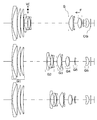
図1は、本件発明に係る実施例1のズームレンズのレンズ構成を示すレンズ断面図であり、図面に向かって上から順に広角端状態、中間焦点距離状態及び望遠端状態における各レンズ断面図を示している。当該ズームレンズは、物体側から順に、正の屈折力の第1レンズ群G1と、負の屈折力の第2レンズ群G2と、正の屈折力の第3レンズ群G3と、正の屈折力の第4レンズ群G4と、負の屈折力の第5レンズ群G5と、正の屈折力の第6レンズ群とから構成されている。
(1) Configuration of Zoom Lens FIG. 1 is a lens cross-sectional view showing the lens configuration of the zoom lens of Example 1 according to the present invention, in the wide-angle end state, intermediate focal length state, and telephoto end in order from the top toward the drawing. Each lens sectional view in a state is shown. The zoom lens includes, in order from the object side, a first lens group G1 having a positive refractive power, a second lens group G2 having a negative refractive power, a third lens group G3 having a positive refractive power, and a positive refractive power. 4th lens group G4, 5th lens group G5 of negative refractive power, and 6th lens group of positive refractive power.
第1レンズ群G1は、物体側から順に配置される、物体側に凸面を向けた負のメニスカスレンズ及び正レンズからなる接合レンズと、正レンズとから構成される。
第2レンズ群G2は、物体側から順に配置された、負レンズと、両凹レンズ及び正レンズからなる接合レンズと、負レンズとから構成される。
第3レンズ群G3は、物体側から順に配置された、正レンズと、物体側に凸面を向けた負のメニスカスレンズとから構成される。
The first lens group G1 includes a cemented lens including a negative meniscus lens having a convex surface directed toward the object side and a positive lens, which are arranged in order from the object side, and a positive lens.
The second lens group G2 includes a negative lens, a cemented lens including a biconcave lens and a positive lens, and a negative lens, which are arranged in order from the object side.
The third lens group G3 includes a positive lens and a negative meniscus lens having a convex surface facing the object side, which are arranged in order from the object side.
第4レンズ群G4は、物体側から順に配置された、両凸レンズと、像側に凸面を向けた負のメニスカスレンズとからなる接合レンズとから構成される。
第5レンズ群G5は、1枚の負レンズから構成される。
第6レンズ群G6は、像側に凸面を向けた1枚の正レンズから構成される。
The fourth lens group G4 includes a cemented lens including a biconvex lens arranged in order from the object side and a negative meniscus lens having a convex surface facing the image side.
The fifth lens group G5 includes one negative lens.
The sixth lens group G6 is composed of one positive lens having a convex surface directed toward the image side.
当該実施例1のズームレンズにおいて、広角端から望遠端への変倍に際して、第1レンズ群G1は固定され、第2レンズ群G2は像側に移動し、第3レンズ群G3及び第4レンズ群G4はいずれも異なる軌跡で、像側に向かって凹の軌跡を描くように移動し、第5レンズ群G5は物体側に移動し、第6レンズ群G6は固定される。これにより、広角端から望遠端への変倍に際して、第1レンズ群及び第2レンズ群の間隔が大きくなり、第2レンズ群及び前記第3レンズ群の間隔が小さくなり、各レンズ群間の間隔が変化する。 In the zoom lens of Example 1, when zooming from the wide-angle end to the telephoto end, the first lens group G1 is fixed, the second lens group G2 moves to the image side, and the third lens group G3 and the fourth lens All of the groups G4 have different loci and move so as to draw a concave locus toward the image side, the fifth lens group G5 moves to the object side, and the sixth lens group G6 is fixed. Thereby, upon zooming from the wide-angle end to the telephoto end, the distance between the first lens group and the second lens group is increased, the distance between the second lens group and the third lens group is decreased, and the distance between the lens groups is increased. The interval changes.
また、無限遠から近接物体への合焦は、第4レンズ群G4を物体側に移動させることで行う。 Further, focusing from infinity to a close object is performed by moving the fourth lens group G4 to the object side.
さらに、第2レンズ群G2は、防振群VCであり、光軸に対して略垂直方向に移動可能に構成されている。第2レンズ群を光軸に対して略垂直方向に移動させることで、光軸に対して略垂直方向に像を移動させて、手振れ等の撮像時の振動に伴う像ブレを補正することができる。 Further, the second lens group G2 is a vibration-proof group VC, and is configured to be movable in a direction substantially perpendicular to the optical axis. By moving the second lens group in a direction substantially perpendicular to the optical axis, the image can be moved in a direction substantially perpendicular to the optical axis, and image blur due to vibration during imaging such as camera shake can be corrected. it can.
なお、図1において、第3レンズ群G3の物体側に示す「S」は開口絞りであり、変倍時に第3レンズ群G3と一体的に移動する。また、第5レンズ群G5の像面側に示す「CG」はカバーガラスであり、ローパスフィルターや赤外カットフィルター等を表す。また、カバーガラスの像側には、CCDセンサやCMOSセンサなどの固体撮像素子の撮像面、或いは、銀塩フィルムのフィルム面等の像面が配置される。これらの符号等は他の実施例で示す各レンズ断面図においても同様である。 In FIG. 1, “S” shown on the object side of the third lens group G3 is an aperture stop, and moves integrally with the third lens group G3 during zooming. Further, “CG” shown on the image plane side of the fifth lens group G5 is a cover glass and represents a low-pass filter, an infrared cut filter, or the like. Further, on the image side of the cover glass, an image plane such as an imaging plane of a solid-state imaging device such as a CCD sensor or a CMOS sensor, or a film plane of a silver salt film is disposed. These symbols and the like are the same in the lens cross-sectional views shown in the other embodiments.
(2)数値実施例
次に、当該ズームレンズの具体的数値を適用した数値実施例について説明する。表1に当該ズームレンズのレンズデータを示す。表1において、「面番号」は物体側から数えたレンズ面の順番、「r」はレンズ面の曲率半径、「d」はレンズ面の光軸上の間隔、「nd」はd線(波長λ=587.6nm)に対する屈折率、「vd」はd線に対するアッベ数をそれぞれ示している。また、レンズ面が非球面である場合には、面番号の後に「*(アスタリスク)」を付し、レンズ面が回折面である場合には、面番号の後に「♯(シャープ)」を付している。レンズ面が非球面又は回折面である場合は、曲率半径「r」の欄には曲率半径を示している。
(2) Numerical Examples Next, numerical examples to which specific numerical values of the zoom lens are applied will be described. Table 1 shows lens data of the zoom lens. In Table 1, “surface number” is the order of the lens surfaces counted from the object side, “r” is the radius of curvature of the lens surfaces, “d” is the distance on the optical axis of the lens surfaces, and “nd” is the d-line (wavelength “vd” indicates the Abbe number with respect to the d-line. When the lens surface is aspheric, “* (asterisk)” is appended to the surface number, and when the lens surface is a diffractive surface, “# (sharp)” is appended to the surface number. doing. When the lens surface is an aspherical surface or a diffractive surface, the radius of curvature “r” indicates the radius of curvature.
表2(2−1)は、非球面データである。表(2−1)には、下記式で定義したときの非球面係数を示す。ただし、表2(2−1)において、「E−a」は、「×10−a」を示す。 Table 2 (2-1) is aspherical data. Table (2-1) shows the aspheric coefficient when defined by the following equation. However, in Table 2 (2-1), “E-a” indicates “× 10-a”.

ただし、上記式において、「r」は曲率、「h」は光軸からの高さ、「k」は円錐係数、「A4」、「A6」、「A8」、「A10」は各次数の非球面係数を示す。 In the above formula, “r” is the curvature, “h” is the height from the optical axis, “k” is the conic coefficient, “A4”, “A6”, “A8”, “A10” Indicates the spherical coefficient.
表2(2−2)及び表2(2−3)に各種データを示す。表(2−2)には、広角端状態、中間焦点距離状態及び望遠端状態における当該ズームレンズ全系の焦点距離(F)、Fナンバー(Fno)、半画角(ω)及び可変間隔(D(i))を示す。また、表2(2−3)に各レンズ群の焦点距離を示す。 Various data are shown in Table 2 (2-2) and Table 2 (2-3). Table (2-2) shows the focal length (F), F number (Fno), half angle of view (ω), and variable interval of the entire zoom lens system in the wide-angle end state, intermediate focal length state, and telephoto end state. D (i)). Table 2 (2-3) shows the focal length of each lens group.
表3は、回折面データである。表3には、下記位相差関数で定義したときの、回折次数(m)、規格化波長(λ)、回折面係数(C01、C02、C03、C04)を示す。ただし、C01、C02、C03、C04はそれぞれ下記位相差関数のC1、C2、C3、C4に対応する。 Table 3 shows diffraction plane data. Table 3 shows the diffraction order (m), normalized wavelength (λ), and diffraction plane coefficients (C01, C02, C03, C04) when defined by the following phase difference function. However, C01, C02, C03, and C04 correspond to the following phase difference functions C1, C2, C3, and C4, respectively.
また、各条件式(1)〜条件式(3)の数値を表12に示す。なお、各表中の長さの単位は全て「mm」であり、画角の単位は全て「°」である。これらの表に関する事項は他の実施例で示す各表においても同様であるため、以下では説明を省略する。 Table 12 shows numerical values of the conditional expressions (1) to (3). The unit of length in each table is “mm”, and the unit of angle of view is “°”. Since the items related to these tables are the same in each table shown in other examples, the description thereof will be omitted below.
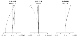
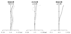
さらに、図2〜図4に当該ズームレンズの広角端状態、中間焦点距離状態、望遠端状態における無限遠合焦時の縦収差図をそれぞれ示す。それぞれの縦収差図は、図面に向かって左から順に、球面収差、非点収差、歪曲収差を表している。球面収差を表す各図では、縦軸は開放F値との割合、横軸にデフォーカスをとり、実線がd線(波長λ=587.6nm)、破線がF線(波長λ=486.1nm)、一点鎖線がC線(波長λ=656.3nm)における球面収差を表す。非点収差を表す各図では、縦軸は像高、横軸にデフォーカスをとり、実線がサジタル面、破線がメリジオナル面での非点収差を表す。歪曲収差を表す各図では、縦軸は像高、横軸に%をとり、歪曲収差を表す。これらの縦収差図に関する事項は他の実施例で示す各図においても同様であるため、以下では説明を省略する。 Furthermore, FIGS. 2 to 4 show longitudinal aberration diagrams of the zoom lens at the infinite focus in the wide-angle end state, the intermediate focal length state, and the telephoto end state, respectively. Each longitudinal aberration diagram represents spherical aberration, astigmatism, and distortion aberration in order from the left toward the drawing. In each diagram showing spherical aberration, the vertical axis is the ratio to the open F value, the horizontal axis is defocused, the solid line is the d line (wavelength λ = 587.6 nm), the broken line is the F line (wavelength λ = 486.1 nm), The alternate long and short dash line represents spherical aberration at the C-line (wavelength λ = 656.3 nm). In each diagram showing astigmatism, the vertical axis represents the image height, the horizontal axis defocused, the solid line represents the astigmatism on the sagittal plane, and the broken line represents the meridional plane. In each diagram showing distortion aberration, the vertical axis represents image height and the horizontal axis represents%, and represents distortion aberration. Since the matters relating to these longitudinal aberration diagrams are the same in the respective drawings shown in the other examples, the description thereof will be omitted below.
(1)光学系の構成
図5は、本件発明に係る実施例2のズームレンズのレンズ構成を示すレンズ断面図である。当該ズームレンズは、物体側から順に、正の屈折力の第1レンズ群G1と、負の屈折力の第2レンズ群G2と、正の屈折力の第3レンズ群G3と、正の屈折力の第4レンズ群G4と、負の屈折力の第5レンズ群G5と、正の屈折力の第6レンズ群とから構成されている。
(1) Configuration of Optical System FIG. 5 is a lens cross-sectional view showing the lens configuration of the zoom lens of Example 2 according to the present invention. The zoom lens includes, in order from the object side, a first lens group G1 having a positive refractive power, a second lens group G2 having a negative refractive power, a third lens group G3 having a positive refractive power, and a positive refractive power. 4th lens group G4, 5th lens group G5 of negative refractive power, and 6th lens group of positive refractive power.
第1レンズ群G1は、物体側から順に配置された、物体側に凸面を向けた負のメニスカスレンズ及び正レンズからなる接合レンズと、正レンズとから構成される。
第2レンズ群G2は、物体側から順に配置された、負レンズと、両凹レンズ及び正レンズからなる接合レンズと、負レンズとから構成される。
第3レンズ群G3は、物体側から順に配置された、正レンズと、物体側に凸面を向けた負のメニスカスレンズとから構成される。
The first lens group G1 includes a cemented lens including a negative meniscus lens and a positive lens arranged in order from the object side and having a convex surface facing the object side, and a positive lens.
The second lens group G2 includes a negative lens, a cemented lens including a biconcave lens and a positive lens, and a negative lens, which are arranged in order from the object side.
The third lens group G3 includes a positive lens and a negative meniscus lens having a convex surface facing the object side, which are arranged in order from the object side.
第4レンズ群G4は、物体側から順に配置された、両凸レンズと、像側に凸面を向けた負のメニスカスレンズとからなる接合レンズとから構成される。
第5レンズ群G5は、1枚の負レンズから構成される。
第6レンズ群G6は、像側に凸面を向けた1枚の正レンズから構成される。
The fourth lens group G4 includes a cemented lens including a biconvex lens arranged in order from the object side and a negative meniscus lens having a convex surface facing the image side.
The fifth lens group G5 includes one negative lens.
The sixth lens group G6 is composed of one positive lens having a convex surface directed toward the image side.
当該実施例2のズームレンズにおいて、広角端から望遠端への変倍に際して、第1レンズ群G1は固定され、第2レンズ群G2は像側に移動し、第3レンズ群G3及び第4レンズ群はいずれも異なる軌跡で、像側に向かって凹の軌跡を描くように移動し、第5レンズ群G5は物体側に移動し、第6レンズ群G6は固定される。これにより、広角端から望遠端への変倍に際して、第1レンズ群及び第2レンズ群の間隔が大きくなり、第2レンズ群及び前記第3レンズ群の間隔が小さくなり、各レンズ群間の間隔が変化する。 In the zoom lens of Embodiment 2, when zooming from the wide-angle end to the telephoto end, the first lens group G1 is fixed, the second lens group G2 moves to the image side, and the third lens group G3 and the fourth lens All the groups move with different trajectories and move toward a concave locus toward the image side, the fifth lens group G5 moves toward the object side, and the sixth lens group G6 is fixed. Thereby, upon zooming from the wide-angle end to the telephoto end, the distance between the first lens group and the second lens group is increased, the distance between the second lens group and the third lens group is decreased, and the distance between the lens groups is increased. The interval changes.
また、無限遠から近接物体への合焦は、第4レンズ群G4を物体側に移動させることで行う。 Further, focusing from infinity to a close object is performed by moving the fourth lens group G4 to the object side.
さらに、第2レンズ群G2は、防振群VCであり、光軸に対して略垂直方向に移動可能に構成されている。第2レンズ群を光軸に対して略垂直方向に移動させることで、光軸に対して略垂直方向に像を移動させて、手振れ等の撮像時の振動に伴う像ブレを補正することができる。 Further, the second lens group G2 is a vibration-proof group VC, and is configured to be movable in a direction substantially perpendicular to the optical axis. By moving the second lens group in a direction substantially perpendicular to the optical axis, the image can be moved in a direction substantially perpendicular to the optical axis, and image blur due to vibration during imaging such as camera shake can be corrected. it can.
(2)数値実施例
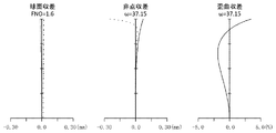
次に、当該ズームレンズの具体的数値を適用した数値実施例について説明する。表4は、当該ズームレンズのレンズデータであり、表5(5−1)は非球面データであり、表5(5−2)及び表5(5−3)は各種データである。また、表6は、回折面データである。また、表12に条件式(1)〜条件式(3)の数値を示す。さらに、図6〜図8は、当該ズームレンズの広角端状態、中間焦点距離状態、望遠端状態における無限遠合焦時の縦収差図である。
(2) Numerical Examples Next, numerical examples to which specific numerical values of the zoom lens are applied will be described. Table 4 shows lens data of the zoom lens, Table 5 (5-1) shows aspheric data, and Table 5 (5-2) and Table 5 (5-3) show various data. Table 6 shows diffraction plane data. Table 12 shows numerical values of the conditional expressions (1) to (3). Further, FIGS. 6 to 8 are longitudinal aberration diagrams when the zoom lens is focused at infinity in the wide-angle end state, the intermediate focal length state, and the telephoto end state.
(1)光学系の構成
図9は、本件発明に係る実施例3のズームレンズのレンズ構成を示すレンズ断面図である。当該ズームレンズは、物体側から順に、正の屈折力の第1レンズ群G1と、負の屈折力の第2レンズ群G2と、正の屈折力の第3レンズ群G3と、正の屈折力の第4レンズ群G4と、負の屈折力の第5レンズ群G5と、正の屈折力の第6レンズ群とから構成されている。
(1) Configuration of Optical System FIG. 9 is a lens cross-sectional view showing the lens configuration of the zoom lens of Example 3 according to the present invention. The zoom lens includes, in order from the object side, a first lens group G1 having a positive refractive power, a second lens group G2 having a negative refractive power, a third lens group G3 having a positive refractive power, and a positive refractive power. 4th lens group G4, 5th lens group G5 of negative refractive power, and 6th lens group of positive refractive power.
第1レンズ群G1は、物体側から順に配置された、物体側に凸面を向けた負のメニスカスレンズ及び正レンズからなる接合レンズと、正レンズとから構成される。
第2レンズ群G2は、物体側から順に配置された、負レンズと、両凹レンズ及び正レンズからなる接合レンズと、負レンズとから構成される。
第3レンズ群G3は、物体側から順に配置された、正レンズと、物体側に凸面を向けた負のメニスカスレンズとから構成される。
The first lens group G1 includes a cemented lens including a negative meniscus lens and a positive lens arranged in order from the object side and having a convex surface facing the object side, and a positive lens.
The second lens group G2 includes a negative lens, a cemented lens including a biconcave lens and a positive lens, and a negative lens, which are arranged in order from the object side.
The third lens group G3 includes a positive lens and a negative meniscus lens having a convex surface facing the object side, which are arranged in order from the object side.
第4レンズ群G4は、物体側から順に配置された、両凸レンズと、像側に凸面を向けた負のメニスカスレンズとからなる接合レンズとから構成される。
第5レンズ群G5は、1枚の負レンズから構成される。
第6レンズ群G6は、像側に凸面を向けた1枚の正レンズから構成される。
The fourth lens group G4 includes a cemented lens including a biconvex lens arranged in order from the object side and a negative meniscus lens having a convex surface facing the image side.
The fifth lens group G5 includes one negative lens.
The sixth lens group G6 is composed of one positive lens having a convex surface directed toward the image side.
当該実施例3のズームレンズにおいて、広角端から望遠端への変倍に際して、第1レンズ群G1は固定され、第2レンズ群G2は像側に移動し、第3レンズ群G3及び第4レンズ群G4はいずれも異なる軌跡で、像側に向かって凹の軌跡を描くように移動し、第5レンズ群G5は物体側に移動し、第6レンズ群G6は固定される。これにより、広角端から望遠端への変倍に際して、第1レンズ群及び第2レンズ群の間隔が大きくなり、第2レンズ群及び前記第3レンズ群の間隔が小さくなり、各レンズ群間の間隔が変化する。 In the zoom lens of Example 3, when zooming from the wide-angle end to the telephoto end, the first lens group G1 is fixed, the second lens group G2 moves to the image side, and the third lens group G3 and the fourth lens All of the groups G4 have different loci and move so as to draw a concave locus toward the image side, the fifth lens group G5 moves to the object side, and the sixth lens group G6 is fixed. Thereby, upon zooming from the wide-angle end to the telephoto end, the distance between the first lens group and the second lens group is increased, the distance between the second lens group and the third lens group is decreased, and the distance between the lens groups is increased. The interval changes.
また、無限遠から近接物体への合焦は、第4レンズ群G4を物体側に移動させることで行う。 Further, focusing from infinity to a close object is performed by moving the fourth lens group G4 to the object side.
さらに、第2レンズ群G2は、防振群VCであり、光軸に対して略垂直方向に移動可能に構成されている。第2レンズ群を光軸に対して略垂直方向に移動させることで、光軸に対して略垂直方向に像を移動させて、手振れ等の撮像時の振動に伴う像ブレを補正することができる。 Further, the second lens group G2 is a vibration-proof group VC, and is configured to be movable in a direction substantially perpendicular to the optical axis. By moving the second lens group in a direction substantially perpendicular to the optical axis, the image can be moved in a direction substantially perpendicular to the optical axis, and image blur due to vibration during imaging such as camera shake can be corrected. it can.
(2)数値実施例
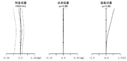
次に、当該ズームレンズの具体的数値を適用した数値実施例について説明する。表7は、当該ズームレンズのレンズデータであり、表8(8−1)は非球面データであり、表8(8−2)及び表8(8−3)は各種データである。また、表9は、回折面データである。また、表12に条件式(1)〜条件式(3)の数値を示す。さらに、図10〜図12は、当該ズームレンズの広角端状態、中間焦点距離状態、望遠端状態における無限遠合焦時の縦収差図である。
(2) Numerical Examples Next, numerical examples to which specific numerical values of the zoom lens are applied will be described. Table 7 shows lens data of the zoom lens, Table 8 (8-1) is aspherical data, and Table 8 (8-2) and Table 8 (8-3) are various data. Table 9 shows diffraction surface data. Table 12 shows numerical values of the conditional expressions (1) to (3). 10 to 12 are longitudinal aberration diagrams of the zoom lens at the time of focusing at infinity in the wide-angle end state, the intermediate focal length state, and the telephoto end state.
(1)光学系の構成
図13は、本件発明に係る実施例4のズームレンズのレンズ構成を示すレンズ断面図である。当該ズームレンズは、物体側から順に、正の屈折力の第1レンズ群G1と、負の屈折力の第2レンズ群G2と、正の屈折力の第3レンズ群G3と、正の屈折力の第4レンズ群G4と、負の屈折力の第5レンズ群G5と、正の屈折力の第6レンズ群とから構成されている。
(1) Configuration of Optical System FIG. 13 is a lens cross-sectional view showing the lens configuration of the zoom lens of Example 4 according to the present invention. The zoom lens includes, in order from the object side, a first lens group G1 having a positive refractive power, a second lens group G2 having a negative refractive power, a third lens group G3 having a positive refractive power, and a positive refractive power. 4th lens group G4, 5th lens group G5 of negative refractive power, and 6th lens group of positive refractive power.
第1レンズ群G1は、物体側から順に配置された、物体側に凸面を向けた負のメニスカスレンズ及び正レンズからなる接合レンズと、正レンズと、正レンズとから構成される。
第2レンズ群G2は、物体側から順に配置された、負レンズと、両凹レンズ及び正レンズからなる接合レンズと、負レンズとから構成される。
第3レンズ群G3は、物体側から順に配置された、正レンズと、物体側に凸面を向けた負のメニスカスレンズとから構成される。
The first lens group G1 includes a cemented lens including a negative meniscus lens and a positive lens, which are arranged in order from the object side, and has a convex surface facing the object side, a positive lens, and a positive lens.
The second lens group G2 includes a negative lens, a cemented lens including a biconcave lens and a positive lens, and a negative lens, which are arranged in order from the object side.
The third lens group G3 includes a positive lens and a negative meniscus lens having a convex surface facing the object side, which are arranged in order from the object side.
第4レンズ群G4は、物体側から順に配置された、両凸レンズと、像側に凸面を向けた負のメニスカスレンズとからなる接合レンズとから構成される。
第5レンズ群G5は、1枚の負レンズから構成される。
第6レンズ群G6は、像側に凸面を向けた1枚の正のメニスカスレンズから構成される。
The fourth lens group G4 includes a cemented lens including a biconvex lens arranged in order from the object side and a negative meniscus lens having a convex surface facing the image side.
The fifth lens group G5 includes one negative lens.
The sixth lens group G6 includes one positive meniscus lens having a convex surface directed toward the image side.
当該実施例4のズームレンズにおいて、広角端から望遠端への変倍に際して、第1レンズ群G1は固定され、第2レンズ群G2は像側に移動し、第3レンズ群G3及び第4レンズ群G4はいずれも異なる軌跡で、像側に向かって凹の軌跡を描くように移動し、第5レンズ群G5は物体側に移動し、第6レンズ群G6は固定される。これにより、広角端から望遠端への変倍に際して、第1レンズ群及び第2レンズ群の間隔が大きくなり、第2レンズ群及び前記第3レンズ群の間隔が小さくなり、各レンズ群間の間隔が変化する。 In the zoom lens of Example 4, when zooming from the wide angle end to the telephoto end, the first lens group G1 is fixed, the second lens group G2 is moved to the image side, and the third lens group G3 and the fourth lens are moved. All of the groups G4 have different loci and move so as to draw a concave locus toward the image side, the fifth lens group G5 moves to the object side, and the sixth lens group G6 is fixed. Thereby, upon zooming from the wide-angle end to the telephoto end, the distance between the first lens group and the second lens group is increased, the distance between the second lens group and the third lens group is decreased, and the distance between the lens groups is increased. The interval changes.
また、無限遠から近接物体への合焦は、第4レンズ群G4を物体側に移動させることで行う。 Further, focusing from infinity to a close object is performed by moving the fourth lens group G4 to the object side.
さらに、第2レンズ群G2は、防振群VCであり、光軸に対して略垂直方向に移動可能に構成されている。第2レンズ群を光軸に対して略垂直方向に移動させることで、光軸に対して略垂直方向に像を移動させて、手振れ等の撮像時の振動に伴う像ブレを補正することができる。 Further, the second lens group G2 is a vibration-proof group VC, and is configured to be movable in a direction substantially perpendicular to the optical axis. By moving the second lens group in a direction substantially perpendicular to the optical axis, the image can be moved in a direction substantially perpendicular to the optical axis, and image blur due to vibration during imaging such as camera shake can be corrected. it can.
(2)数値実施例
次に、当該ズームレンズの具体的数値を適用した数値実施例について説明する。表10は、当該ズームレンズのレンズデータであり、表11(11−1)は非球面データであり、表11(11−2)及び表11(11−3)は各種データである。また、表12に条件式(1)〜条件式(3)の数値を示す。さらに、図14〜図16は、当該ズームレンズの広角端状態、中間焦点距離状態、望遠端状態における無限遠合焦時の縦収差図である。
(2) Numerical Examples Next, numerical examples to which specific numerical values of the zoom lens are applied will be described. Table 10 shows lens data of the zoom lens, Table 11 (11-1) is aspherical data, and Table 11 (11-2) and Table 11 (11-3) are various data. Table 12 shows numerical values of the conditional expressions (1) to (3). Further, FIGS. 14 to 16 are longitudinal aberration diagrams at the time of focusing at infinity in the wide-angle end state, the intermediate focal length state, and the telephoto end state of the zoom lens.
本件発明によれば、高い変倍比を有し、且つ、変倍域全域にわたって良好な光学性能を有する小型のズームレンズ及び撮像装置を提供することができる。 According to the present invention, it is possible to provide a small zoom lens and an imaging apparatus that have a high zoom ratio and have good optical performance over the entire zoom range.
G1・・・第1レンズ群
G2・・・第2レンズ群
G3・・・第3レンズ群
G4・・・第4レンズ群
G5・・・第5レンズ群
G6・・・第6レンズ群
VC・・・防振群
S・・・絞り
CG・・・カバーガラス
G1 ... 1st lens group G2 ... 2nd lens group G3 ... 3rd lens group G4 ... 4th lens group G5 ... 5th lens group G6 ... 6th lens group VC- ..Anti-vibration group S ... Aperture CG ... Cover glass
Claims (11)
前記第5レンズ群は負の屈折力を有し、少なくとも当該第5レンズ群を移動させることで広角端から望遠端への変倍を行い、
以下の条件式を満足することを特徴とするズームレンズ。
(1) 4.0< β5T <6.0
ただし、
β5Tは、望遠端における前記第5レンズ群の横倍率である。 It is composed of a first lens group, a second lens group, a third lens group, a fourth lens group, a fifth lens group, and a sixth lens group, which are arranged in order from the object side.
The fifth lens group has a negative refractive power, and performs zooming from the wide-angle end to the telephoto end by moving at least the fifth lens group,
A zoom lens satisfying the following conditional expression:
(1) 4.0 <β5T <6.0
However,
β5T is the lateral magnification of the fifth lens group at the telephoto end.
(2) nd5>1.85
ただし、
nd5は、前記第5レンズ群を構成する負レンズのd線に対する屈折率である。 The zoom lens according to any one of claims 1 to 5, wherein the fifth lens group includes one negative lens, and satisfies the following conditional expression.
(2) nd5> 1.85
However,
nd5 is a refractive index with respect to d-line of the negative lens constituting the fifth lens group.
以下の条件式を満足する請求項1から請求項8のいずれか一項に記載のズームレンズ。
(3) 0.15<F1/Ft<0.35
ただし、
F1は、第1レンズ群の焦点距離であり、
Ftは、望遠端における当該ズームレンズ全系の焦点距離である。 The first lens group includes a cemented lens including one negative lens and one positive lens arranged in order from the object side, and at least one positive single lens.
The zoom lens according to claim 1, wherein the following conditional expression is satisfied.
(3) 0.15 <F1 / Ft <0.35
However,
F1 is the focal length of the first lens group,
Ft is the focal length of the entire zoom lens system at the telephoto end.
Priority Applications (2)
| Application Number | Priority Date | Filing Date | Title |
|---|---|---|---|
| JP2015087844A JP6568709B2 (en) | 2015-04-22 | 2015-04-22 | Zoom lens and imaging device |
| CN201610248303.4A CN106066530B (en) | 2015-04-22 | 2016-04-20 | Zoom lens and photographic device |
Applications Claiming Priority (1)
| Application Number | Priority Date | Filing Date | Title |
|---|---|---|---|
| JP2015087844A JP6568709B2 (en) | 2015-04-22 | 2015-04-22 | Zoom lens and imaging device |
Publications (2)
| Publication Number | Publication Date |
|---|---|
| JP2016206410A true JP2016206410A (en) | 2016-12-08 |
| JP6568709B2 JP6568709B2 (en) | 2019-08-28 |
Family
ID=57419950
Family Applications (1)
| Application Number | Title | Priority Date | Filing Date |
|---|---|---|---|
| JP2015087844A Active JP6568709B2 (en) | 2015-04-22 | 2015-04-22 | Zoom lens and imaging device |
Country Status (2)
| Country | Link |
|---|---|
| JP (1) | JP6568709B2 (en) |
| CN (1) | CN106066530B (en) |
Families Citing this family (6)
| Publication number | Priority date | Publication date | Assignee | Title |
|---|---|---|---|---|
| JP2018194750A (en) * | 2017-05-19 | 2018-12-06 | 富士フイルム株式会社 | Zoom lens and imaging apparatus |
| CN108227154A (en) * | 2018-03-26 | 2018-06-29 | 中国计量大学 | A kind of mobile phone wide-angle zoom lens |
| JP7032226B2 (en) * | 2018-04-27 | 2022-03-08 | 株式会社タムロン | Zoom lens and image pickup device |
| CN114615400A (en) * | 2019-01-03 | 2022-06-10 | 核心光电有限公司 | Camera, double camera and triple camera |
| CN112904542B (en) * | 2021-01-28 | 2022-03-04 | 中国科学院西安光学精密机械研究所 | Low-distortion high-definition continuous zooming optical system |
| CN114994885B (en) * | 2022-06-17 | 2023-09-01 | 湖南长步道光学科技有限公司 | Full-frame optical system with micro-distance function and movie lens |
Citations (8)
| Publication number | Priority date | Publication date | Assignee | Title |
|---|---|---|---|---|
| JPH10333038A (en) * | 1997-06-05 | 1998-12-18 | Minolta Co Ltd | Zoom lens |
| JPH1172705A (en) * | 1997-08-29 | 1999-03-16 | Tochigi Nikon:Kk | Zoom lens provided with two and more focusing lens groups |
| JP2008261996A (en) * | 2007-04-11 | 2008-10-30 | Sony Corp | Zoom lens and imaging apparatus |
| JP2009192771A (en) * | 2008-02-14 | 2009-08-27 | Sony Corp | Zoom lens, image pickup apparatus, and control method for zoom lens |
| US20120268830A1 (en) * | 2011-04-22 | 2012-10-25 | Ability Enterprise Co., Ltd. | Zoom lens |
| JP2013097324A (en) * | 2011-11-04 | 2013-05-20 | Nikon Corp | Variable power optical system, optical apparatus, and method of manufacturing variable power optical system |
| JP2014102462A (en) * | 2012-11-22 | 2014-06-05 | Canon Inc | Zoom lens and image capturing device having the same |
| JP2014145960A (en) * | 2013-01-30 | 2014-08-14 | Canon Inc | Zoom lens and imaging apparatus having the same |
Family Cites Families (3)
| Publication number | Priority date | Publication date | Assignee | Title |
|---|---|---|---|---|
| KR100604310B1 (en) * | 2004-04-23 | 2006-07-25 | 삼성테크윈 주식회사 | High magnification zoom lens |
| US7864443B2 (en) * | 2007-12-07 | 2011-01-04 | Ricoh Company, Ltd. | Zoom lens, imaging apparatus, and personal data assistant |
| JP6220555B2 (en) * | 2013-05-24 | 2017-10-25 | 株式会社タムロン | Zoom lens and imaging device |
-
2015
- 2015-04-22 JP JP2015087844A patent/JP6568709B2/en active Active
-
2016
- 2016-04-20 CN CN201610248303.4A patent/CN106066530B/en active Active
Patent Citations (8)
| Publication number | Priority date | Publication date | Assignee | Title |
|---|---|---|---|---|
| JPH10333038A (en) * | 1997-06-05 | 1998-12-18 | Minolta Co Ltd | Zoom lens |
| JPH1172705A (en) * | 1997-08-29 | 1999-03-16 | Tochigi Nikon:Kk | Zoom lens provided with two and more focusing lens groups |
| JP2008261996A (en) * | 2007-04-11 | 2008-10-30 | Sony Corp | Zoom lens and imaging apparatus |
| JP2009192771A (en) * | 2008-02-14 | 2009-08-27 | Sony Corp | Zoom lens, image pickup apparatus, and control method for zoom lens |
| US20120268830A1 (en) * | 2011-04-22 | 2012-10-25 | Ability Enterprise Co., Ltd. | Zoom lens |
| JP2013097324A (en) * | 2011-11-04 | 2013-05-20 | Nikon Corp | Variable power optical system, optical apparatus, and method of manufacturing variable power optical system |
| JP2014102462A (en) * | 2012-11-22 | 2014-06-05 | Canon Inc | Zoom lens and image capturing device having the same |
| JP2014145960A (en) * | 2013-01-30 | 2014-08-14 | Canon Inc | Zoom lens and imaging apparatus having the same |
Also Published As
| Publication number | Publication date |
|---|---|
| JP6568709B2 (en) | 2019-08-28 |
| CN106066530B (en) | 2018-11-23 |
| CN106066530A (en) | 2016-11-02 |
Similar Documents
| Publication | Publication Date | Title |
|---|---|---|
| JP5213898B2 (en) | Zoom lens system, interchangeable lens device and camera system | |
| JP5135723B2 (en) | Zoom lens having image stabilization function, image pickup apparatus, image stabilization method for zoom lens, and zooming method for zoom lens | |
| JP6568709B2 (en) | Zoom lens and imaging device | |
| JP5893959B2 (en) | Zoom lens | |
| JPWO2006090660A1 (en) | Zoom lens system, imaging device and camera | |
| JP5358229B2 (en) | Inner zoom type and inner focus type zoom lens with anti-vibration function | |
| JP2018169564A (en) | Zoom lens and imaging apparatus | |
| JP2007286446A (en) | Zoom lens and imaging apparatus equipped therewith | |
| JP2017207668A (en) | Variable power optical system and imaging apparatus | |
| JP2018169563A (en) | Zoom lens and imaging apparatus | |
| JP2008039838A (en) | Zoom lens system, image pickup apparatus, and camera | |
| JP6553984B2 (en) | Zoom lens and imaging apparatus | |
| JP6555920B2 (en) | Zoom lens and imaging device | |
| JP2016024341A (en) | Zoom lens and image capturing device having the same | |
| JP6354257B2 (en) | Variable magnification optical system and imaging apparatus | |
| US10831005B2 (en) | Variable magnification optical system, optical apparatus, and variable magnification optical system manufacturing method | |
| JP7170502B2 (en) | Zoom lens and imaging device | |
| JP6098176B2 (en) | Variable-magnification optical system, optical device, and variable-magnification optical system manufacturing method | |
| WO2014069077A1 (en) | Inner focus type lens | |
| JP6563200B2 (en) | Zoom lens and imaging device | |
| JP6588221B2 (en) | Zoom lens and imaging device | |
| JP6518067B2 (en) | Optical system and imaging device | |
| JP6354256B2 (en) | Variable magnification optical system and imaging apparatus | |
| JP5866190B2 (en) | Zoom lens and imaging device | |
| JP5987543B2 (en) | Zoom lens, optical device |
Legal Events
| Date | Code | Title | Description |
|---|---|---|---|
| A621 | Written request for application examination |
Free format text: JAPANESE INTERMEDIATE CODE: A621 Effective date: 20171226 |
|
| A131 | Notification of reasons for refusal |
Free format text: JAPANESE INTERMEDIATE CODE: A131 Effective date: 20190109 |
|
| A601 | Written request for extension of time |
Free format text: JAPANESE INTERMEDIATE CODE: A601 Effective date: 20190227 |
|
| A521 | Request for written amendment filed |
Free format text: JAPANESE INTERMEDIATE CODE: A523 Effective date: 20190423 |
|
| TRDD | Decision of grant or rejection written | ||
| A01 | Written decision to grant a patent or to grant a registration (utility model) |
Free format text: JAPANESE INTERMEDIATE CODE: A01 Effective date: 20190709 |
|
| A61 | First payment of annual fees (during grant procedure) |
Free format text: JAPANESE INTERMEDIATE CODE: A61 Effective date: 20190805 |
|
| R150 | Certificate of patent or registration of utility model |
Ref document number: 6568709 Country of ref document: JP Free format text: JAPANESE INTERMEDIATE CODE: R150 |
|
| R250 | Receipt of annual fees |
Free format text: JAPANESE INTERMEDIATE CODE: R250 |
|
| R250 | Receipt of annual fees |
Free format text: JAPANESE INTERMEDIATE CODE: R250 |